Actuator - Armatec
Actuator - Armatec
Actuator - Armatec

Create successful ePaper yourself
Turn your PDF publications into a flip-book with our unique Google optimized e-Paper software.
<strong>Actuator</strong><br />
Ajac, electrical<br />
AT 3851<br />
Ajac, Edition AT electrical 3, 2009-05-13<br />
Sidhuvud1 AT<br />
<strong>Actuator</strong><br />
AT<br />
AT 3851<br />
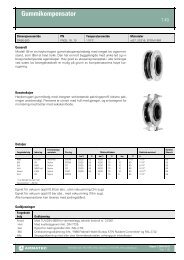
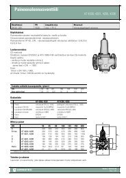
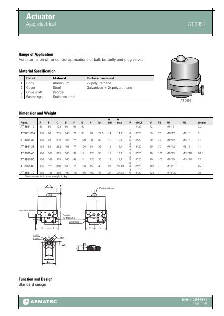
Range of Application<br />
<strong>Actuator</strong> for on-off or control applications of ball, butterfly and plug valves.<br />
Material Specification<br />
Detail Material Surface treatment<br />
1 Body Aluminium 2x polyurethane<br />
2 Cover Steel Galvanized + 2x polyurethane<br />
3 Drive shaft Bronze<br />
4 Fastenings Stainless steel<br />
AT 3851<br />
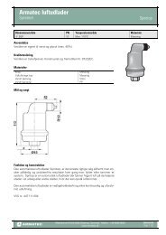
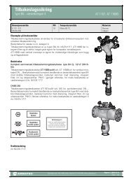
Dimension and Weight<br />
Fig no. A B C D F G H M<br />
O<br />
min<br />
O<br />
max P Mx1,5 V1 V2 W1 W2 Weight<br />
AT 3851-10 80 50 123 85 50 80 1*20 42 M6* 9 2,2<br />
AT3851-20A 130 60 255 145 70 95 90 27,5 14 14,11<br />
1<br />
8 3*20 50 70 M6*12 M8*15 6<br />
AT 3851-30 135 82 292 165 77 120 90 33 19 19,11<br />
2<br />
5 3*20 50 70 M6*12 M8*15 11<br />
AT 3851-35 135 82 292 165 77 120 90 33 19 19,11<br />
2<br />
5 3*20 50 70 M6*12 M8*15 11<br />
AT 3851-40 170 109 315 165 96 141 125 33 19 19,11<br />
2<br />
5 3*20 70 102 M8*15 M10*18 16,5<br />
AT 3851-50 170 109 315 165 96 141 125 33 19 19,11<br />
2<br />
5 3*20 70 102 M8*15 M10*18 17<br />
AT 3851-60 195 128 318 165 123 166 150 48 27 27,13<br />
3<br />
6 3*20 102 - M10*18 - 25,5<br />
AT 3851-70 195 128 356 190 123 166 150 48 27 27,13<br />
3<br />
6 3*20 125 - M12*20 - 26<br />
Measurements in mm, weight in kg<br />
D<br />
Position indicator<br />
OPEN<br />
CLOSED<br />
Manual operation<br />
C<br />
Entries<br />
3x M20x1.5<br />
Limit stops<br />
A<br />
B<br />
F<br />
G<br />
4 x W2<br />
4 x W1<br />
P<br />
O<br />
M<br />
N<br />
V1<br />
V2<br />
H<br />
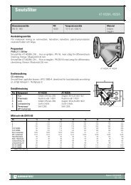
Function and Design<br />
Standard design<br />
Edition 3, 2009-05-13<br />
Page 1 (4)
<strong>Actuator</strong><br />
Ajac, electrical AT 3851<br />
Reversible actuator in 10 sizes for turning 0–90°, adjustable by use of a combination<br />
of position limit switch, mechanical limit switch and/or torque switch.*<br />
Motor cover with protection dome with underlying visual indicator. <strong>Actuator</strong> size<br />
10 with position indication on drive shaft.<br />
The motor and other electrical components are fully isolated from the gear body.<br />
The motor is protected against thermal overload by a thermostatic switch in the<br />
winding and the larger models also have torque switch.*A heater element keeps<br />
the motor space free from moist. The worm gears for sizes 20A–70 are self-breaking,<br />
permanently lubricated and provided with manual emergency manoeuvring.<br />
Size 10 has spur gearing.<br />
The actuator connection to valves are in acc. to ISO 5211, with internal square<br />
size for 20A–80 and external drive shaft for size 10.<br />
* Varies with actuator sizes, see section ’Technical data’.<br />
Standard perfomance<br />
Standard perfomance<br />
<strong>Actuator</strong> size 10 20A-70<br />
Operation 50% ED 30% ED<br />
Protection class IP65 IP 65<br />
Temperature -20°C till +70°C -20°C till +70°C<br />
Heater - 10W<br />
Overload protection Thermo switch Thermo/torque switch*<br />
Permanen lubricated gear Spurgear Self-inhibiting worm gear<br />
Cable gland M20x1,5 M20x1,5<br />
Limit switches 250V, max 10A 250V, 16A<br />
Torque switches - 250V, 16A<br />
Terminal block 8 con. 12 con.<br />
*Is not valid for 20A which only is performed with thermo switch.<br />
Thechnical Data<br />
<strong>Actuator</strong> size 10 20A 30 35 40 50 60 70<br />
Torque:<br />
Start/Stop Nm 18 55 100 150 200 350 500 800<br />
Running Nm 14 20 35 53 70 123 175 280<br />
Speed (50 Hz) s 6,5 6 7 9 13,5 23 25,5 25,5<br />
Torque switch - - 2 2 2 2 2 2<br />
Limit switch 2 4 4 4 4 4 4 4<br />
Mechanical stop ±5° - 2 2 2 2 2 2 2<br />
Visual indicator - yes yes yes yes yes yes yes<br />
Emegency manouvre - yes yes yes yes yes yes yes<br />
ISO-connection F04 F05/F07 F05/F07 F05/F07 F07/F10 F07/F10 F10 F10<br />
Rätten till ändringar utan föregående meddelande förbehålls.<br />
<strong>Armatec</strong> ansvarar inte för eventuella tryckfel eller missförstånd.<br />
Dokumenten får kopieras endast i sin helhet.<br />
Edition 3, 2009-05-13<br />
Page 2 (4)
<strong>Actuator</strong><br />
Ajac, electrical<br />
AT 3851<br />
Electrical Data<br />
Electrical data<br />
<strong>Actuator</strong> size 10 20A 30 35 40 50 60 70<br />
Start current(A) 230 VAC 0,1 0,6 1,7 1,7 1,7 1,7 1,7 2,3<br />
110 VAC 0,55 1,1 2,9 2,9 2,9 2,9 2,9 4,5<br />
400 VAC - 0,4 0,7 0,7 0,7 0,7 0,7 0,9<br />
460 VAC - 0,37 0,63 0,63 0,63 0,63 0,63 0,87<br />
24 VAC 0,8 5 9 9 9 9 - -<br />
Mark current (A) 230 VAC 0,1 0,5 1,1 1,1 1,1 1,1 1,1 1,8<br />
110 VAC 0,45 1,1 2,1 2,1 2,1 2,1 2,1 2,8<br />
400 VAC - 0,2 0,4 0,4 0,4 0,4 0,4 0,54<br />
460 VAC - 0,18 0,45 0,45 0,45 0,45 0,45 0,57<br />
24 VAC 0,15 1,7 4,8 4,8 6,3 6,3 - -<br />
Power (W) 230 VAC 40 72 200 200 200 200 200 305<br />
110 VAC 45 100 225 225 225 225 225 315<br />
400 VAC - 80 145 145 145 145 145 165<br />
460 VAC - 77 180 180 180 180 180 200<br />
Cosς PHI 230 VAC 0,82 0,91 0,82 0,82 0,82 0,82 0,82 0,77<br />
110 VAC - 0,84 0,98 0,98 0,98 0,98 0,98 0,93<br />
400 VAC - 0,54 0,51 0,51 0,51 0,51 0,51 0,47<br />
460 VAC - 0,54 0,50 0,50 0,50 0,50 0,50 0,44<br />
Dimensioning<br />
<strong>Actuator</strong> size 10* 20A 30 35 40 50 60 70<br />
Valve<br />
Δ p, bar<br />
Ball valve 3-pcs<br />
AT 3502-3552<br />
reduced bore 25 DN 8-25 15-50 65 80 100 125-150 200 -<br />
Ball valve Ajtec<br />
AT 3533-3534<br />
full bore 25 DN - 15-50 65 80 100 - - -<br />
Ball valve flanged<br />
AT 3580-3585<br />
full bore 16 DN - 15-40 50 65-80 100 125 150 200<br />
Butter fly valve<br />
Eurovalve<br />
AT 2300-2344 10 DN - 50-80 100-150 - 200 - 250 300-350<br />
* Select AT 3851-20 if built-in emergency operation, speed control etc. is required. .<br />
Dimensioning is general and does not take into account changes which affect the torque of the valves.<br />
Accessories and Options<br />
Speed control*<br />
Feedback potentiometer<br />
Position transmitter 4–20mA*<br />
Positioner 4–20mA* or 0–10 V*<br />
Local control switch*<br />
Protection class IP 67<br />
180° rotation<br />
Epoxy coated<br />
* Not actuator size 10.<br />
Edition 3, 2009-05-13<br />
Page 3 (4)
<strong>Actuator</strong><br />
Ajac, electrical AT 3851<br />
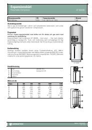
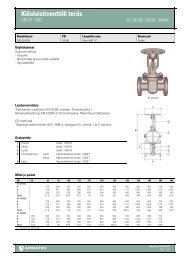
EX execution<br />
EX performance: AT 3851 EX<br />
EX class:<br />
II2GEEx d IIB T4 acc. to EN50018-1977/EN50014-1977<br />
Certificate no.: KEMA ATEX 2156X<br />
For actuator size: 20A ≤ 70 and local manouvre AT 3851-107EX<br />
Voltage;<br />
110, 230 och 400 VAC<br />
Technical data: acc. to standard actuator AT 3851<br />
Electrical data: acc. to standard actuator AT 3851<br />
Dimensioning: acc. to standard actuator AT 3851<br />
EEX d-design allows all standard accessories to be mounted in the<br />
motor-space.<br />
AT 3851EX<br />
Installation<br />
During all work with the actuator the power must be disconnected.<br />
The actuator must be connected as per the wiring diagram.<br />
Each actuator must be powered by individual switch or relay contact, minimum<br />
16A,to prevent cross-feed between the actuators.<br />
At outdoor installation, the actuator should be protected by a roof or cap, alternatively<br />
choose an actuator with protection class IP67.<br />
Installation with motor downwards should be avoided.<br />
Turn the valve with the control unit’s hand wheel to centre position. See indication<br />
on top of device.<br />
Always connect the heater.<br />
Check that the actuator turns the valve in the desired direction.<br />
The correct limit switch (open or closed) shall break the motor current.<br />
Cable entries must comply at least to the lowest protection class of devices.<br />
EX actuator must be connected as per applicable standards.<br />
Min. 5 threads, min. 8 mm.<br />
Marking<br />
Article no., manufacturer, model, serial no., voltage and current ratings.<br />
EX-device also with EExd IIB T4, certificate no. and test station.<br />
wiring diagram is located in motor space.<br />
How to order<br />
Example: AT 3851-20AC24<br />
AT 3851 -20 AC24<br />
Fig. no. <strong>Actuator</strong> size Voltage<br />
Rätten till ändringar utan föregående meddelande förbehålls.<br />
<strong>Armatec</strong> ansvarar inte för eventuella tryckfel eller missförstånd.<br />
Dokumenten får kopieras endast i sin helhet.<br />
Edition 3, 2009-05-13<br />
Page 4 (4)