HPS.08.047.100 Revision: 00
HPS.08.047.100 Revision: 00
HPS.08.047.100 Revision: 00

Create successful ePaper yourself
Turn your PDF publications into a flip-book with our unique Google optimized e-Paper software.
<strong>HPS.08.047.1<strong>00</strong></strong><br />
<strong>Revision</strong>: <strong>00</strong><br />
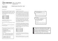
Hauptständer KAWASAKI KLR 650<br />
Centre Stand<br />
Montagehinweise<br />
Alle vom Motorrad gelösten Schrauben sind gemäß<br />
Herstellerangaben wieder zu montieren, oder mit von<br />
SW-MOTECH gelieferten Schrauben zu ersetzen. Falls<br />
nicht anderweitig definiert, diese Schrauben nach<br />
Tabelle anziehen.<br />
M6<br />
M8<br />
M10<br />
9,6 Nm<br />
23 Nm<br />
46 Nm<br />
Gegebenenfalls Schrauben mit flüssiger<br />
Schraubensicherung einkleben.<br />
Prüfen Sie nach 50 km alle Verbindungen auf festen<br />
Sitz.<br />
Die Kurvenfreiheit kann durch einen Hauptständer<br />
eingeschränkt werden<br />
Mounting Instructions<br />
Centerstand cornering clearance:<br />
SW-MOTECH centerstands are carefully designed and<br />
tested to eliminate reductions in cornering clearance<br />
and ground clearance under most driving conditions<br />
on an unmodified stock motorcycle, and are certified<br />
to be compliant with European ABE safety standards.<br />
Use of any centerstand may reduce corning clearance<br />
or ground clearance under extreme driving situations.<br />
SW-MOTECH products should be installed by a qualified,<br />
experienced motorcycle technician. If you are unsure<br />
of your ability to properly install a product, please<br />
have the product installed by your local motorcycle<br />
dealer. SW-MOTECH takes no responsibility for damages<br />
caused by improper installation.<br />
All screws, bolts and nuts, including all replacement<br />
hardware provided by SW-MOTECH, should be tightened<br />
to the torque specified in the OEM maintenance manual<br />
for your motorcycle. If no torque specifications are<br />
provided in the OEM maintenance manual, the following<br />
torques may be used:<br />
1<br />
2<br />
3<br />
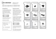
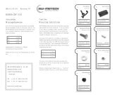
Hauptständer<br />
Center Stand<br />
HPS.08.047.9<strong>00</strong><br />
Anzahl/ Pcs. 1<br />
ZFD.<strong>00</strong>.150.<strong>00</strong>3<br />
Anzahl/ Pcs. 1<br />
KES.<strong>00</strong>.20.20/b<br />
<strong>00</strong><br />
Zugfedersatz<br />
Spring Set<br />
Rohrendkappe<br />
Plastic Cap<br />
5<br />
6<br />
7<br />
Anbauplatte mit<br />
Federumlekung<br />
Right Side Bracket<br />
(with Spring Pin)<br />
HPS.08.047.901<br />
rechts/right<br />
HPS.08.047.902<br />
02<br />
Anzahl/ Pcs. 1<br />
Anbauplatte<br />
Left Side Bracket<br />
links/left<br />
02<br />
Anzahl/ Pcs. 1<br />
Innensechskantschraube<br />
Hexagon Socket Screw<br />
M8 x 30 DIN 912<br />
SW-MOTECH GmbH & Co. KG<br />
M6<br />
9,6 Nm<br />
Anzahl/ Pcs. 2<br />
Anzahl/ Pcs. 4<br />
Bahnhofstrasse 44d<br />
35282 Rauschenberg<br />
-Germany-<br />
M8<br />
M10<br />
23 Nm<br />
46 Nm<br />
4<br />
Anschlag<br />
Rubber Element<br />
8<br />
Unterlegscheibe<br />
Washer<br />
Tel.: ++ 49 (0) 6425 816 8<strong>00</strong><br />
Fax: ++ 49 (0) 6425 816 810<br />
All screws, bolts and nuts should be checked after<br />
driving the first 50 km to ensure that all are tightened<br />
to the proper torque.<br />
www.sw-motech.com<br />
Medium strength liquid thread-locker (i.e., "Locktite")<br />
should be used to secure all screws, bolts and nuts.<br />
MSS.<strong>00</strong>.03.016<br />
Anzahl/ Pcs. 1<br />
A 8,4 DIN 125<br />
Anzahl/ Pcs. 4
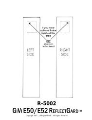
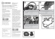
Montageanleitung:<br />
1.- Kunststoffanschlag (4) in die rechte Anbaubplatte (5)<br />
einsetzen. Der Bund muß dabei vollständig in der Vertiefung<br />
sitzen.<br />
2.- Die Rohrkappen (8) beidseitig in das Vierkantrohr einsetzen.<br />
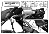
3.- Fußrastenhalter auf beiden Seiten abschrauben.<br />
4.- Die rechte Anbaubplatte mit Federanlenkung (5) zusammen<br />
mit dem Fußrastenhalter verschrauben. Hierzu die mitgelieferten<br />
Innensechskantschrauben (7) und Unterlegscheiben(8)<br />
verwenden. Achtung: flüssige Schraubensicherung verwenden!<br />
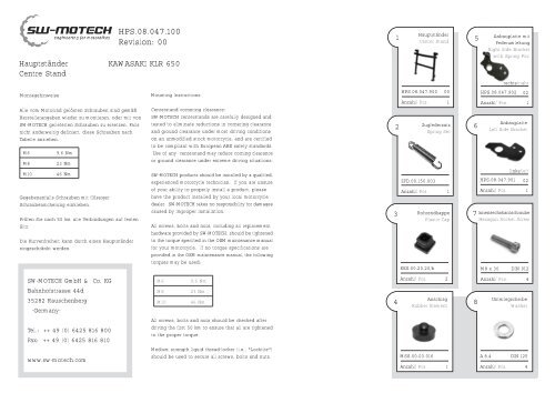
5.- Hauptständer (1) in die Bohrung der Anbaubplatte (5)<br />
einsetzen und linke Anschraubplatte (6) auf Hauptständer<br />
aufstecken. Achtung: beim Einstecken des Hauptsänders auf<br />
die Anbauplatte Fett benutzen!<br />
6.- Mit Unterlegscheibe (8) und Innensechskantschraube (7)<br />
linke Anbaubplatte (6) zusammen mit der Fußraste<br />
verschrauben. Achtung: flüssige Schraubensicherung<br />
verwenden!<br />
7.- Federsatz (2) an dem Stift der rechten Anbaubplatte (5)<br />
einhängen. Danach mit einem Schraubenzieher oder Zange<br />
am Hauptständer einhängen.<br />
8.- Nach erfolgter Montage Funktion des Ständers und<br />
Schrauben auf festen Sitz prüfen.<br />
Assembly instruction:<br />
4<br />
1<br />
!<br />
Mit<br />
Fett einsetzen<br />
Insert with grease<br />
7 8<br />
5<br />
5<br />
2<br />
<strong>HPS.08.047.1<strong>00</strong></strong><br />
1.- Insert rubber element (4) into Right Side Bracket (5). The<br />
flange must sit completely in the recess.<br />
2.- Insert the plastic caps (8) into the square tube on both<br />
ends.<br />
3.- Detach the footrests on both sides.<br />
4.- Attach the Right Side Bracket (5) together with the footrest.<br />
Use hexagon socket screw (7) and washer (8) to fix the parts.<br />
Attention: use liquid screw locker!<br />
5.- Insert the center stand (1) into the hole of the mounted<br />
Right Side Bracket (5) and insert the Left Side Bracket (6)<br />
onto the left side of the center stand (1). Attention: use grease<br />
at the pivot points between the Side Brackets (5) & (6) and<br />
center stand (1).<br />
6.- Attach Left Side Bracket (6) with hexagon socket screw<br />
(7) and washer (8) together with the footrest. Attention: use<br />
liquid screw locker!<br />
7.- First hook the spring set (2) on the pin of the Right Side<br />
Bracket (5). Then pull the other end with a screwdriver or<br />
pliers onto the pin of the center stand.<br />
8.- After mounting check the function of the center stand (1).<br />
Fahrtrichtung<br />
Driving Direction<br />
!<br />
Alle Schrauben mit<br />
Schraubensicherung einsetzen.<br />
Insert all screws with liquid thread<br />
lock.<br />
! Achtung:<br />
Die Kurven- und Bodenfreiheit kann<br />
durch einen Hauptständer<br />
eingeschränkt werden.<br />
Attention:<br />
Cornering and ground clearance can<br />
be reduced by using a center stand.