Intercalation of Lithium Ions into Graphite Electrodes Studied by AC ...
Intercalation of Lithium Ions into Graphite Electrodes Studied by AC ...
Intercalation of Lithium Ions into Graphite Electrodes Studied by AC ...

Create successful ePaper yourself
Turn your PDF publications into a flip-book with our unique Google optimized e-Paper software.
<strong>of</strong> conducting analysis <strong>of</strong> heavily convoluted frequency dispersion<br />
data <strong>by</strong> deconvoluting the complex responses <strong>into</strong> those <strong>of</strong> simple<br />
subcomponents. This approach combined with the general nonlinear<br />
least-squares fitting procedure allowed us to construct equivalent circuits<br />
whose simulated responses describe actually measured data<br />
well. From this simulation, values <strong>of</strong> various circuit components<br />
were obtained.<br />
In the present work, a constant phase element (CPE or Q) is used<br />
for equivalent circuits except for resistors, R. The general expression<br />
for the admittance response <strong>of</strong> the CPE is 19<br />
YCPE � Yc�n cos(n�/2) � jYC�n sin(n�/2) [2]<br />
where � is the angular frequency, which is 2�f with f being frequency<br />
and j � (�1) 1/2 . Depending on the n value, the CPE can have<br />
a variety <strong>of</strong> responses. If n � 0, it represents a resistance with R �<br />
Y �1<br />
c ; if n � 1, a capacitance with C � YC, and if n � 0.5, a Warburg<br />
response.<br />
Results and Discussion<br />
Chronopotentiometric responses.—A major problem encountered<br />
during the electrochemical lithium intercalation reaction in the PCbased<br />
electrolytes is the excessive electrolyte decomposition reaction<br />
during the first lithiation process. Much effort has been expended to<br />
overcome these problems. 7-10,20 Fong et al. 10 reported that introducing<br />
a cosolvent, EC, <strong>into</strong> the PC-based electrolyte improves the reversibility<br />
<strong>of</strong> Li/graphite cells. Other workers8,9,20 suggested that<br />
crown ethers reduce the degree <strong>of</strong> PC decomposition reactions when<br />
used as an additive. We examined effects <strong>of</strong> the electrolyte composition<br />
on the PC decomposition <strong>by</strong> recording chronopotentiograms in<br />
four different electrolyte solutions (see Fig. 1) under otherwise-identical<br />
experimental conditions. In Fig. 1, the period during which the<br />
potential plateau is maintained at around �0.8 V corresponding to the<br />
PC decomposition reaction21 changes with the electrolyte composition.<br />
In 0.1 M LiClO4-PC/EC with 0.1 M 12-crown-4 added, the period<br />
for the plateau is the shortest. A serious capacity loss is observed<br />
in the 0.1 M LiClO4-PC solution, as can be seen from the long potential<br />
plateau corresponding to the PC decomposition reaction. Similar<br />
results were reported <strong>by</strong> Shu and co-workers. 9 Fong et al. 10 concluded<br />
that the PC decomposition reaction at the graphite electrode is<br />
associated with Li� solvated with PC molecules which become cointercalated<br />
<strong>into</strong> the graphite layers. The addition <strong>of</strong> EC or crown ethers<br />
to the electrolyte may change the solvation structure and appears to<br />
suppress the cointercalation process, resulting in the reduction <strong>of</strong> the<br />
PC decomposition reaction.<br />
According to Fong et al., 10 the PC decomposition reaction results<br />
in the formation <strong>of</strong> passive films on the graphite electrode surface. Reversible<br />
Li intercalation still takes place on the film-covered graphite<br />
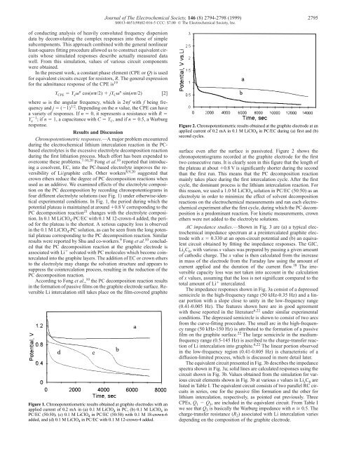
Figure 1. Chronopotentiometric results obtained at graphite electrodes with an<br />
applied current <strong>of</strong> 0.2 mA in (a) 0.1 M LiClO 4 in PC, (b) 0.1 M LiClO 4 in<br />
PC/EC (50:50), (c) 0.1 M LiClO 4 in PC/EC (50:50) with 0.1 M 18-crown-6<br />
added, and (d) 0.1 M LiClO 4 in PC/EC with 0.1 M 12-crown-4 added.<br />
Journal <strong>of</strong> The Electrochemical Society, 146 (8) 2794-2798 (1999) 2795<br />
S0013-4651(98)02-016-5 CCC: $7.00 © The Electrochemical Society, Inc.<br />
Figure 2. Chronopotentiometric results obtained at the graphite electrode at an<br />
applied current <strong>of</strong> 0.2 mA in 0.1 M LiClO 4 in PC/EC during (a) first and (b)<br />
second cycles.<br />
surface even after the surface is passivated. Figure 2 shows the<br />
chronopotentiograms recorded at the graphite electrode for the first<br />
two consecutive runs. It is clearly seen in this figure that the length <strong>of</strong><br />
the plateau at about �0.8 V is significantly shorter during the second<br />
than the first run. This means that the PC decomposition reaction<br />
mainly takes place during the first intercalation cycle. After the first<br />
cycle, the dominant process is the lithium intercalation reaction. For<br />
this reason, we used a 1.0 M LiClO4 solution in PC/EC (50:50) as an<br />
electrolyte in order to minimize the effect <strong>of</strong> solvent decomposition<br />
reactions on the electrochemical measurements and ran each electrochemical<br />
experiment after the first cycle, during which the PC decomposition<br />
is a predominant reaction. For kinetic measurements, crown<br />
ethers were not added to the electrolyte solutions.<br />
<strong>AC</strong> impedance studies.—Shown in Fig. 3 are (a) a typical electrochemical<br />
impedance spectrum at a preintercalated graphite electrode<br />
with x � 0.330 at an open-circuit potential and (b) an equivalent<br />
circuit obtained <strong>by</strong> fitting the impedance responses. The GIC,<br />
LixC6 , with various x values was prepared <strong>by</strong> passing a given amount<br />
<strong>of</strong> cathodic charge. The x value is then calculated from the increase<br />
in mass <strong>of</strong> the electrode from the Faraday law using the amount <strong>of</strong><br />
current applied and the duration <strong>of</strong> the current flow. 18 The irreversible<br />
capacity loss was not taken <strong>into</strong> account in the calculation<br />
<strong>of</strong> x values, assuming that the loss is not significant compared to the<br />
total amount <strong>of</strong> Li� intercalated.<br />
The impedance responses shown in Fig. 3a consist <strong>of</strong> a depressed<br />
semicircle in the high-frequency range (50 kHz-0.35 Hz) and a linear<br />
portion with a slope close to unity in the low-frequency range<br />
(0.41-0.005 Hz). The features shown here are in good agreement<br />
with those reported in the literature6,22 under similar experimental<br />
conditions. The depressed semicircle is shown to consist <strong>of</strong> two arcs<br />
from the curve-fitting procedure. The small arc in the high-frequency<br />
range (50 kHz-150 Hz) is attributed to the formation <strong>of</strong> a passive<br />
film on the graphite surface. 22 The large semicircle in the mediumfrequency<br />
range (0.5-145 Hz) is ascribed to the charge-transfer reaction<br />
<strong>of</strong> Li intercalation <strong>into</strong> graphite. 6,22 The linear portion observed<br />
in the low-frequency region (0.41-0.005 Hz) is characteristic <strong>of</strong> a<br />
diffusion-limited process, which is discussed in more detail later.<br />
The equivalent circuit presented in Fig. 3b describes the impedance<br />
spectra shown in Fig. 3a; solid lines are calculated responses using the<br />
circuit shown in Fig. 3b. Values obtained from the simulation for various<br />
circuit elements shown in Fig. 3b at various x values in LixC6 are<br />
listed in Table I. The equivalent circuit consists <strong>of</strong> two parallel RC circuits<br />
in series, one for the passive film formation and the other for<br />
lithium intercalation, respectively, as pointed out previously. Three<br />
CPEs, Q1 � Q3 , are included in the equivalent circuit. From Table I<br />
we see that Q3 is basically the Warburg impedance with n � 0.5. The<br />
charge-transfer resistance (R2) associated with Li intercalation varies<br />
depending on the composition <strong>of</strong> the graphite electrode.