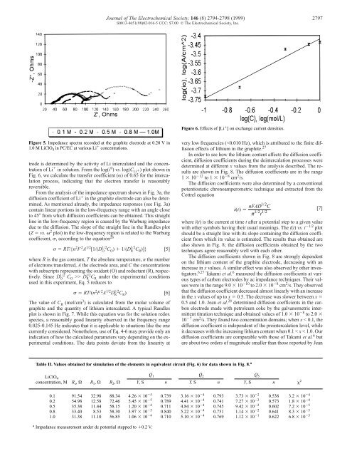
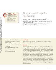
Figure 5. Impedance spectra recorded at the graphite electrode at 0.20 V in 1.0 M LiClO 4 in PC/EC at various Li � concentrations. trode is determined <strong>by</strong> the activity <strong>of</strong> Li intercalated and the concentration <strong>of</strong> Li � in solution. From the log(i 0 ) vs. log(C Li�) plot shown in Fig. 6, we calculate the transfer coefficient (�) <strong>of</strong> 0.65 for the intercalation process, indicating that the electron transfer is reasonably reversible. From the analysis <strong>of</strong> the impedance spectrum shown in Fig. 3a, the diffusion coefficient <strong>of</strong> Li � in the graphite electrode can also be determined. As mentioned already, the impedance responses (see Fig. 3a) contain linear portions in the low-frequency range with an angle close to 45� from which diffusion coefficients can be obtained. This straight line in the low-frequency region is caused <strong>by</strong> the Warburg impedance due to the diffusion. The slope <strong>of</strong> the straight line in the Randles plot (Z � vs. � 2 plot) in the low-frequency region is related to the Warburg coefficient, �, according to the equation 26 Journal <strong>of</strong> The Electrochemical Society, 146 (8) 2794-2798 (1999) 2797 S0013-4651(98)02-016-5 CCC: $7.00 © The Electrochemical Society, Inc. � � RT/{n 2 F 2 A 1/2 [1/(D O 1/2 CO ) � 1/(D R 1/2 CR )]} [5] where R is the gas constant, T the absolute temperature, n the number <strong>of</strong> electrons transferred, A the electrode area, and C the concentrations with subscripts representing the oxidant (O) and reductant (R), respectively. Since D O 1/2 CO >> D R 1/2 CR under the experimental conditions used in this experiment, Eq. 5 reduces to � � RT/(n 2 F 2 A 1/2 D R 1/2 CR ) [6] The value <strong>of</strong> C R (mol/cm 3 ) is calculated from the molar volume <strong>of</strong> graphite and the quantity <strong>of</strong> lithium intercalated. A typical Randles plot is shown in Fig. 7. While this equation was for the solution redox species, a reasonably good linearity observed in the frequency range 0.025-0.145 Hz indicates that it is applicable to situations like the one currently considered. Nonetheless, use <strong>of</strong> Eq. 4-6 may provide only an indication <strong>of</strong> how the calculated parameters vary depending on the experimental conditions. The data points deviate from the linearity at Figure 6. Effects <strong>of</strong> [Li � ] on exchange current densities. Table II. Values obtained for simulation <strong>of</strong> the elements in equivalent circuit (Fig. 6) for data shown in Fig. 8. a very low frequencies (
2798 Journal <strong>of</strong> The Electrochemical Society, 146 (8) 2794-2798 (1999) S0013-4651(98)02-016-5 CCC: $7.00 © The Electrochemical Society, Inc. Figure 7. A typical Randles plot in a lower frequency region shown in Fig. 5b. et al. 28 This is perhaps because the structures <strong>of</strong> the carbon they used were different from ours and Takami’s. In our case, the diffusion coefficient is seen to decrease significantly between x � 0.1 and 0.4 and then levels <strong>of</strong>f when x is greater than 0.4. We believe that the break point <strong>of</strong> the two domains is related to the structural change <strong>of</strong> graphite during intercalation. Also, the intercalation between Li � and the graphite host lattice would be responsible for the changes in diffusion coefficients. 25,29 While abrupt changes in diffusion coefficients were observed due to the structural modification in the host material during the intercalation <strong>of</strong> Li <strong>into</strong> a cathode material such as V 2 O 5 25 or that Na <strong>into</strong> molybdates 29 depending on the x values, the change is relatively smooth and continuous in our case. This means that graphite undergoes its structural modification gradually in a continuous fashion rather than an abrupt change in the crystal structure. Conclusion We see from our results that the diffusion coefficients are strongly dependent on the electrode composition. The diffusion coefficients decrease with an increase in x in the GIC, Li x C 6 . There are two domains in how the diffusion coefficients are distributed depending on the level <strong>of</strong> preintercalation. When x < �0.4 or so, the diffusion coefficients decrease rapidly with an increase <strong>of</strong> the x value. Above this, the diffusion coefficients stay approximately constant. The kinetic parameters <strong>of</strong> lithium intercalation have been obtained from ac impedance measurements. The exchange current densities are in the range 1.4-2.4 mA/cm 2 depending on the Li content <strong>of</strong> the graphite electrode, and the transfer coefficient was determined to be 0.65. Overall, the lithium intercalation/deintercalation reaction is electrochemically reversible, although it displays chemical irreversibility at initial stages due to the effective reaction <strong>of</strong> intercalated lithium with solvent. Once its surface is passivated, a reasonably reversible lithium intercalation reaction takes place. The solution resistance decreases as the electrolyte concentration increases. The decrease, however, slows down beyond about 0.8 M LiClO 4 . It appears that the electrolyte concentration higher than 1 M does not provide benefits in terms <strong>of</strong> solution resistance for actual battery operations. The drastic decrease in diffusion coefficients beyond x > 0.4 would result in a decrease in power densities <strong>of</strong> the lithium-ion intercalation batteries. Acknowledgment This work was supported <strong>by</strong> a grant from Korea Electrotechnology Research Institute (KERI) and Research and Development Man- Figure 8. Effects <strong>of</strong> x values in Li x C 6 on diffusion coefficients. The values determined <strong>by</strong> the ac impedance method refer to diffusion coefficients <strong>of</strong> Li atom, while those determined <strong>by</strong> the chronoamperometric method refer to diffusion coefficients <strong>of</strong> Li � ion. agement Center for Energy and Resources (R<strong>AC</strong>ER). This work was performed at the Department <strong>of</strong> Chemistry, University <strong>of</strong> New Mexico, Albuquerque, NM, as part <strong>of</strong> the T.P.’s dissertation. Pohang University <strong>of</strong> Science and Technology assisted in meeting the publication costs <strong>of</strong> this article. References 1. B. Scrosati, J. Electrochem. Soc., 139, 2776 (1992). 2. D. Aurbach and Y. Ein-Eli, J. Electrochem. Soc., 142, 1746 (1995). 3. K. Tatsumi, N. Iwashita, H. Sakaebe, H. Shioyama, and S. Higuchi, J. Electrochem. Soc., 142, 716 (1995). 4. T. Ohzuku, Y. Iwakoshi, and K. Sawai, J. Electrochem. Soc., 140, 2490 (1993). 5. R. Yazami and Ph. Touzain, J. Power Sources, 9, 365 (1983). 6. N. Takami, A. Satoh, M. Hara, and T. Ohsaki, J. Electrochem. Soc., 142, 371 (1995). 7. Z. Jiang, M. Alamgir, and K. M. Abraham, J. Electrochem. Soc., 142, 333 (1995). 8. M. Morita, H. Hayashida, and Y. Matsuda, J. Electrochem. Soc., 134, 2107 (1987). 9. Z. X. Shu, R. S. McMillan, and J. J. Murray, J. Electrochem. Soc., 140, 922 (1993). 10. R. Fong, U. von Sacken, and J. R. Dahn, J. Electrochem. Soc., 137, 2009 (1990). 11. J. Farcy, R. Messina, and J. Perichon, J. Electrochem. Soc., 137, 1337 (1990). 12. N. Kumagai, Y. Matsuura, and K. Tanno, J. Electrochem. Soc., 139, 3553 (1992). 13. N. Kumagai, T. Fujiwara, and K. Tanno, J. Electrochem. Soc., 140, 3194 (1993). 14. K. Kanehori, F. Kirino, T. Kudo, and K. Miyauchi, J. Electrochem. Soc., 138, 2216 (1991). 15. D. Guyomard and J. M. Tarascon, J. Electrochem. Soc., 139, 937 (1992). 16. A. S. Baranski and W. R. Fawcett, J. Electrochem. Soc., 129, 901 (1982). 17. J. E. Fischer and T. E. Thompson, Physics Today, 31, 36 (1978). 18. J. R. Dahn, Phys. Rev. B, 44, 9170 (1991). 19. B. A. Boukamp, Equivalent Circuit User’s Manual, University <strong>of</strong> Twente, 2nd ed., (1989). 20. J. R. Dahn, R. Fong, and M. J. Spoon, Phys. Rev. B, 42, 6424 (1990). 21. A. N. Dey and B. P. Sullivan, Phys. Rev., 117, 222 (1970). 22. R. Yazami and D. Guerard, J. Power Sources, 43-44, 39 (1993). 23. A. J. Bard and L. R. Faulkner, Electrochemical Methods, Fundamentals and Applications, Chap. 3 and 9, John Wiley & Sons, Inc., New York (1980). 24. N. Takami, A. Satoh, M. Hara, and T. Ohsaki, J. Electrochem. Soc., 142, 2564 (1995). 25. S. Colson, L. C. Klein, J. M. Tarascon, and D. Guyomard, J. Electrochem. Soc., 139, 2359 (1992). 26. A. J. Bard and L. R. Faulkner, Electrochemical Methods, Fundamentals and Applications, p. 328, John Wiley and Sons, Inc., New York (1980). 27. C. Ho, I. D. Raistrick, and R. A. Huggins, J. Electrochem. Soc., 127, 343 (1980). 28. M. Jean, C. Desnoyer, A. Tranchant, and R. Messina, J. Electrochem. Soc., 142, 2122 (1995). 29. J. Farcy, R. Messina, and J. Perichon, J. Electrochem. Soc., 137, 1337 (1990).