TECHNICAL DATASHEET Incremental Encoder RI 58-G / RI 58TG
TECHNICAL DATASHEET Incremental Encoder RI 58-G / RI 58TG
TECHNICAL DATASHEET Incremental Encoder RI 58-G / RI 58TG

Create successful ePaper yourself
Turn your PDF publications into a flip-book with our unique Google optimized e-Paper software.
<strong>TECHNICAL</strong> <strong>DATASHEET</strong><br />
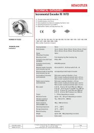
<strong>Incremental</strong> <strong>Encoder</strong> <strong>RI</strong> <strong>58</strong>-G / <strong>RI</strong> <strong>58</strong>TG<br />
<strong>TECHNICAL</strong> DATA<br />
electrical (continued)<br />
Pulse width error<br />
± max. 25° electrical<br />
Number of pulses 50 ... 2500<br />
Alarm output<br />
NPN-O.C., max. 5 mA<br />
Pulse shape<br />
Square wave<br />
Pulse duty factor 1:1<br />
1<br />
With push-pull (K): pole protection<br />
MOUNTING NECESSITIES<br />
In order to be able to compensate an axial and radial misalignment of the shaft, the encoder<br />
flange must not be fixed rigidly. Fix the flanges by means of a stator coupling (e.g.<br />
hubshaft with tether) as torque support (see "Accessories") or by means of a cylindrical<br />
pin:<br />
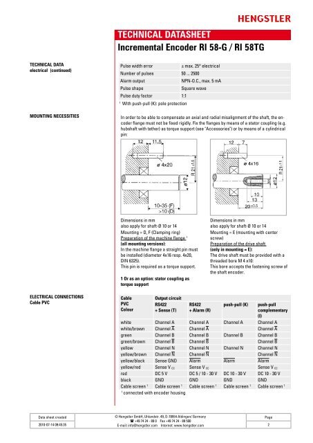
Dimensions in mm<br />
also apply for shaft-Ø 10 or 14<br />
Mounting = D, F (Clamping ring)<br />
Preparation of the machine flange 1<br />
(all mounting versions):<br />
In the machine flange a straight pin must<br />
be installed (diameter 4x16 resp. 4x20,<br />
DIN 6325).<br />
This pin is required as a torque support.<br />
1 Or as an option: stator coupling as<br />
torque support<br />
Dimensions in mm<br />
also apply for shaft-Ø 10 or 14<br />
Mounting = E (mounting with center<br />
screw)<br />
Preparation of the drive shaft<br />
(only in mounting = E):<br />
The drive shaft must be provided with a<br />
threaded bore M 4 x10:<br />
This bore accepts the fastening screw of<br />
the shaft encoder.<br />
ELECT<strong>RI</strong>CAL CONNECTIONS<br />
Cable PVC<br />
Cable<br />
PVC<br />
Colour<br />
Output circuit<br />
RS422<br />
+ Sense (T)<br />
RS422<br />
+ Alarm (R)<br />
push-pull (K)<br />
push-pull<br />
complementary<br />
(I)<br />
white Channel A Channel A Channel A Channel A<br />
white/brown Channel A Channel A Channel A<br />
green Channel B Channel B Channel B Channel B<br />
green/brown Channel B Channel B Channel B<br />
yellow Channel N Channel N Channel N Channel N<br />
yellow/brown Channel N Channel N Channel N<br />
yellow/black Sense GND Alarm Alarm Alarm<br />
yellow/red Sense V CC Sense V CC Sense V CC<br />
red DC 5 V DC 5 / 10 - 30 V DC 10 - 30 V DC 10 - 30 V<br />
black GND GND GND GND<br />
Cable screen 1 Cable screen 1 Cable screen 1 Cable screen 1 Cable screen 1<br />
1<br />
connected with encoder housing<br />
Data sheet created<br />
© Hengstler GmbH, Uhlandstr. 49, D-78554 Aldingen/ Germany<br />
Page<br />
( +49 74 24 - 89 0 Fax +49 74 24 - 89 500<br />
2010-07-14 09:45:35 E-mail: info@hengstler.com Internet: www.hengstler.com<br />
2