FX-500 Catalog - Panasonic Electric Works Corporation of America
FX-500 Catalog - Panasonic Electric Works Corporation of America
FX-500 Catalog - Panasonic Electric Works Corporation of America
You also want an ePaper? Increase the reach of your titles
YUMPU automatically turns print PDFs into web optimized ePapers that Google loves.
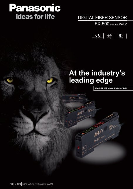
DIGITAL FIBER SENSOR<strong>FX</strong>-<strong>500</strong> SERIES Ver.2Conforming to EMC Directive Listing CertifiedAt the industry’sleading edge<strong>FX</strong>-SERIES HIGH END MODEL2012.08 panasonic.net/id/pidsx/global
CONCEPTIndustry leading stabilityDecrease the variation among fiber sensorsHigh stability!“Why are the values different even for the same detection?” “If we try to forcibly unify all the displayvalues <strong>of</strong> incident light intensity, we will not be able to read the actual changes.”SUNX focuses on the variation among fiber sensors and aims for absolute digitalization.When the <strong>FX</strong>-<strong>500</strong> series is used together with our super quality fiber, the incident light intensityvariation among units is decreased to only 1/4 <strong>of</strong> that <strong>of</strong> conventional models.By being close to absolute values instead <strong>of</strong> modified digital values, changes in detection that couldnot be found in the past can now be monitored.Super quality fiber+Threshold value<strong>FX</strong>-<strong>500</strong> seriesIncident light intensity1Previous amplifierThreshold value1234Incident light intensityDigital control is essentially achievedStability <strong>of</strong> the incident light intensity is improvedby 4 times*.Values <strong>of</strong> incident light intensity stay closetogether even after replacing an amplifier.* Using a small diameter fiber (fiber core ø0.5 mm ø0.020 in).If using a standard fiber (fiber core ø1.0 mm ø0.039 in), the variationwill be double <strong>of</strong> that <strong>of</strong> conventional models.234Large variation in incidentlight intensity.Incident light intensitiesare stable.Incident light intensity1 2 3 4Requires setting differentthreshold values for eachsensor.1/4incident lightintensity variation[from previous]1 2 3 4Can control by usingjust one threshold value.Specifying just one valuein an operation manualis possibleIn the case where multiple fiber sensors areinstalled under the same operatingconditions, the incident light intensities arenearly identical to each other, allowing forthe specification <strong>of</strong> one threshold across allsensors.Maintenance is easy onstabilized fiber sensorsBecause the incident light intensity isstable, the same threshold value can beused even when an amplifier is replaced.Also, copying <strong>of</strong> settings is easy when usedtogether with optical communication.Stability in incident lightintensity and confidence inbeam adjustmentWhen setting up fiber sensors in a row in thesame layout, all incident light intensities willdisplay nearly identical values once beams arealigned. This helps to raise installationprecision and prevent trouble from occurringbefore equipment is turned on.Improved fiber coupling efficiencyand suppressed variation amongunitsIn each unit we have accurately aligned the central axis <strong>of</strong>the fiber with the central axis <strong>of</strong> the emitted light, whichcreates a high coupling efficiency that helps to reducevariation among units.Active coupling emission deviceFiber insertion guideFiber coreAll sensors are aligned individually.Fiber central axisBeamcentralaxis01 <strong>FX</strong>-<strong>500</strong>SERIES* Illustration is image only.
“Super quality fiber” withstable emission amount“Stabilized incident light intensities” even in multiple unitsCONCEPTA quality that surpassed standard fiberIntroducing super quality fiberNew fibers developed using a new manufacturing method adopted by our own factory along witha persistent quality control systemThe basic performance <strong>of</strong> a standard fiber is greatly enhanced!Stable emission intensity±10ø2.2 mm ø0.087 in standard fiberVariation in emission intensity <strong>of</strong> the fibercore is controlled down to less than ±10 %,achieving a stable detection.New materialSingle core standard fiberwith high flexibilityPreviousIn general, high-flexibilitytypes adopt a multi-fiber corewhich may result in largevariation in light emission.Expanded temperature rangeMore flexible!R4Ambient temperature [– 40 to +70 °C – 40 to +158 °F in previous]Bending radius [Previous is R25 mm R0.984 in]–55 to+80 °C–67 to+176 °F1.2 timesmore thanpreviousR4mmR0.157in1/6<strong>of</strong> that <strong>of</strong>previousIntegrated high-precision plugThe centering precision <strong>of</strong>the fiber core attached to theinserting plug is doubled.As the insertion precision isincreased, the variation amongunits can be greatly suppressed.More bendable!Bending durability [Previous is 1,000 times]10 milliontimes10,000 timesmore than previous±10Variation in emissionintensity is down toless than ±10 %Under our new manufacturingmethod and quality control system,we have developed fiber heads thathave a stabilized light emission.When used with the <strong>FX</strong>-<strong>500</strong> amplifier,a complete digital control isessentially achieved.Super quality fiber reduces optical transmission loss to less than ±10 %Point 1Point 2Point 3The beam axis deviation <strong>of</strong> eachunit is kept within ±2 ° and thebeam axis centering precision iskept within ±150 μm ±5.906 mil.High precision polishing is accomplishedby using the PCTM polishing technique.The specularity <strong>of</strong> the end face <strong>of</strong> thefiber is 5 times greater.A high precision integrated plug isachieved with the centeringprecision <strong>of</strong> the fiber core being±40 μm 1.575 mil.* For custom-ordered fibers <strong>of</strong> your required length, contact the sales <strong>of</strong>fice near you.<strong>FX</strong>-<strong>500</strong>SERIESmore thanpreviousApprox. 2 times02
CONCEPTIndustry leading sensing performanceUltra high-speed & Ultra long range detectionThe exclusive detection IC combined with the high intensity beam emitted from the active coupling emission deviceprovides the capability <strong>of</strong> <strong>of</strong>fering high-speed response time over a longer sensing range, opening up new possibilities forfiber sensor detection.Max. 25 μs response time<strong>FX</strong>-<strong>500</strong> with its ultra high response time improves productivity.Performing minute object detection when using a small diameter fiber is now possiblewith a high response time and longer sensing range.H y p e rHYPR mode incorporated<strong>FX</strong>-<strong>500</strong> in combination with small diameter fibers which can handlechallenging detections, allows super long sensing range.<strong>FX</strong>-<strong>500</strong>HYPR modeFD-41Max.5.7 times!longer than the previous modelPrevious<strong>FX</strong>-301 (LONG mode)FD-NFM2Long sensing range with smalldiameter fibersSmall diameter fibers with a compact head can perform longrange and stable detection for minute objects.Long sensing range even inhigh speed modeA high speed response time <strong>of</strong> 25 μs, which is 2.6times more than previous, and a long sensingrange are now possible in high speed mode.Satisfyingboth highspeed andlong rangeThe active coupling emission device efficientlyfocuses the beam through small diameter fibersThe super fine optical lens and emitting element are combinedinto one device enabling the beam emitted from the emittingelement to be focused directly into the fiber.Coupling efficiency is therefore increased by 50 % comparedto standard fiber (core ø1 mm ø0.039 in). In particular, thesmall diameter fibers (core ø0.5 mm ø0.020 in) see a dramaticincrease in light intensity, making challenging detectionspossible.03 <strong>FX</strong>-<strong>500</strong>SERIESConventionalFiber sensorWithout lensEmitting elementCoupling efficiency approx. 10 %<strong>FX</strong>-300Built-in optical lensDouble coupling lensFour-chemicalemitting elementCoupling efficiency approx. 20 %Coupling efficiency = (light intensity directed into the fiber / emission intensity <strong>of</strong> active coupling emission device) × 100<strong>FX</strong>-<strong>500</strong>Emitting element in a deviceActive coupling emission deviceSuperfine optical lensHigh luminancefour-chemicalemitting elementCoupling efficiency more than 50 %* Illustration is image only.
CONCEPTSharp detection with suppressed hysteresisA different accuracy!<strong>FX</strong>-<strong>500</strong> with its accurate detection catches fractional difference inlight intensity, fulfilling high precision and low-hysteresis applications.Retroreflectivetype fiberH-02 modeLong range detection <strong>of</strong>small objects with smalldifference in light intensity<strong>FX</strong>-<strong>500</strong> series achieves a long sensing range by its suppressedhysteresis and high intensity beam. Detection <strong>of</strong> minute objects overa long range is now more accurate compared to the past.Short Sensing renge LongComparison image <strong>of</strong> optimal sensing regionOptimal sensing regionConventionalmodel<strong>FX</strong>-<strong>500</strong>(H-02)Long range detection<strong>of</strong> a glass target is nowpossible due to theability <strong>of</strong> the sensor todetect small changes inlight intensity.ReflectorH-01 modeHighly accuratedetection while avoidingsaturationEven when the received light becomessaturated, the <strong>FX</strong>-<strong>500</strong> series cuts downhysteresis to the utmost limit in order toproduce the optimal margin for detection.Short Sensing renge LongComparison image <strong>of</strong> optimal sensing regionOptimal sensing regionHigh light intensity (saturation) regionConventionalmodel<strong>FX</strong>-<strong>500</strong>(H-01)Light saturated regionis reduced, anddetection is possibleeven under high lightintensity.Three hysteresis modesHysteresis is the difference in incidentlight intensity at the points when theoutput turns ON and when the outputturns OFF. Hysteresis was originallyintended to be used as a measureagainst vibrations, but SUNXprovides three hysteresis modes tosuit the need <strong>of</strong> fiber sensors.ONOFFSmallHysteresisOFF Point ON PointIncident light intensityLargeMode tableModeH-01H-02H-03HysteresisamountMinimalSmallLargeLightintensitySmallLargeLargeDescriptionSharp detection with highaccuracy is possible in this mode.Optimal for minute object detectionwhere light saturates easily.Initial setting mode.Accurate detection such aslong range detection <strong>of</strong> a largeglass substrate is possible.A mode used for chatteringprevention.<strong>Works</strong> in adverse environmentssuch as vibration or dirt.Short Sensing renge LongConventionalmodelH-01 H-02<strong>FX</strong>-<strong>500</strong>Low light intensity regionOptimal sensing regionHigh light intensity (saturation) regionH-02 addresses longsensing range and lowlight intensity region.Ex. Detecting large glass substrateH-01 addresses shortsensing range andhigh light intensity region.Ex. Detecting wire<strong>FX</strong>-<strong>500</strong>SERIES04
OPERATIONClass leading form and operabilityNew form!Previous spaceFlat display with wide viewing angleThe large and high-contrast 7-segment display <strong>of</strong> high luminance provides clear visibilityfrom a wide angle <strong>of</strong> view.Compact cover does not get in the wayReduced to 1/3 <strong>of</strong> that <strong>of</strong> previousClearly visible evenfrom sidewaysR23 mmR0.906 inStreamlined fiber clutchWhile the conventional fiber installation is done after opening up thecover, the <strong>FX</strong>-<strong>500</strong> series adopts a guard structure, eliminating thecover so that the fiber installation can be done in one step.MODE NAVI + Direct settingMODE NAVI uses three indicators and a dual display to show theamplifier’s basic operations. The current operation mode can beconfirmed at a glance, so even a first time user can easily operate theamplifier.Streamlined fiber clutchClutch leverFiber installation takes one step due to the eliminated cover.ConventionalLarge cover model takes 3 steps.NAVI display (lights out during RUN mode)L/DSwitches output operation.L: Light-ON D: Dark-ONCUSTAllows direct change by selecting one <strong>of</strong> the setting <strong>of</strong> responsetime / hysteresis / emitting power. (Initial setting: response time)PROAllows the selection <strong>of</strong> advanced functionssuch as timer, copy, and memory functions.Guard structureConventionalDirect settingDirect adjustmentDirect teachingThe guard structureincorporated preventsthe lever fromdisengaging due toaccidental impact.The lever is exposed and maybe accidentally disengaged.Threshold value can be changed during RUN mode.Teaching can be done during RUN mode.Press onceeach for object“present” and“absent”05 <strong>FX</strong>-<strong>500</strong>SERIES
A variety <strong>of</strong> functions at the industry’s leading edgeFUNCTIONResolves variation in incident light intensity displayDisplay adjustment settingEven if there is no problem in detection, the variation in display may make itdifficult for an operator to verify proper operation. By using the displayadjustment setting, random values can be adjusted, and the visual variationcan be resolved to help define proper operation in an operation manual.DisplayadjustmentsettingVariation in incident light intensityUnify incident light intensity into any valueStable detection over long and short periodsStabilized emission intensityThe “four-chemical emitting element” was first incorporated in theconventional model <strong>FX</strong>-300 to maintain a stable level <strong>of</strong> light emission andhas now become an industry standard. <strong>FX</strong>-<strong>500</strong> series continues to adoptthe same emitting element as well as the “APC (Auto Power Control) circuit”which improves stability in short periods such as when the power is turnedon.Light emiting amountStable sensing comparisonShort-term stabilityDeviationFour-chemical emitting element + APC(<strong>FX</strong>-<strong>500</strong>)Three-chemical emitting element(without APC)Long-term stabilityTimeSaves maintenance timeThreshold tracking functionThis function seeks changes in the light emitting amount resulting fromchanges in the environment over long periods (such as dust levels), so thatthe incident light intensity can be checked at desired intervals and thethreshold values can be reset automatically.LargeIncident lightintensitySmallSHIFT(Tracking by limit teaching)Effective for thru-beam typeand retroreflective type! (Dark-ON)CurrentvalueThresholdvalueTimeLimit teaching is performedperiodically.AUTO(Tracking by automatic teaching)Effective for reflective type!LargeIncident lightintensitySmallONOFFThresholdvalueCurrentvalueTimeAutomatic teaching whichtriggers output is performed.Suitable for preventative maintenanceSelf-diagnosis output<strong>FX</strong>-502(P) / 505(P)-C2 canset Output 2 as self-diagnosisoutput. When Output 1’sthreshold value teaching iscarried out, Output 2 is setconcurrently with the settingrandomly shifted by theamount <strong>of</strong> surplus <strong>of</strong>threshold value.<strong>FX</strong>-502(P) / 505(P)-C2Detect drops in light intensity(e.g. used in dusty environment)Self-diagnosis can be used with the threshold trackingfunction for added effectiveness.LargeIncident light intensitySmallChange in light intensityOutput 2thresholdvalueOutput 1threshold valueAuto setto 50%Self-diagnasis output (alarm)TimeTeaching again(preventative maintenance)Auto setto 50% again<strong>FX</strong>-<strong>500</strong>SERIES06
FUNCTIONA variety <strong>of</strong> functions at the industry’s leading edgeStable detection while being eco-friendlyEmission power & gain settingFor cases when the incident light intensitysaturates the receiver, the light intensitycan be attenuated to the optimal level byAUTO without changing the responsetime. This allows for stable detectionwhile maintaining an optimal S/N ratioand saves energy by controlling theemitting electric current.Detecting a transparent sheetObject presentObject absentNormalAUTOSaturatedAuto mode (AUTO) and 3-level manual mode (3 levels: H / M / L [adjustable]) are incorporated.Built-in logic functionsNo PLC necessary saving material and programming costsLogical calculation functionsThree logical calculations (AND, OR, XOR),are selectable using Output 1 <strong>of</strong> multiple<strong>FX</strong>-<strong>500</strong> series amplifiers.A PLC is not required which helps to reducematerial and programming and costs.Detection fiberSynchronization fiberCalculation <strong>of</strong> two neighboring amplifiersCalculation resultLower side Output 1outputUpper side Output 1 Normal operationCommunicationdirectionCalculation <strong>of</strong> two outputs in one amplifier <strong>FX</strong>-502(P) / 505(P)-C2Calculation <strong>of</strong> one amplifier and external inputOutput 1 Calculation result outputOutput 2 Normal output operation<strong>FX</strong>-502(P) / 505(P)-C2External input(sensor, contact, PLC, etc.)Output 1 Calculation result outputEquipped with 5 types timersA wide variety <strong>of</strong> timer control operations can becarried out by these fiber sensors alone.Time chartSensingconditionON-delayOFF-delayONE-SHOTON-delay •OFF-delayON-delay •ONE-SHOTT1For L-ONT1T1T1T1T1T2T1T2BeamreceivedBeaminterruptedONOFFONOFFONOFFONOFFONOFFTimer period: 0.05 ms to 32 sOutput 1 has ON-delay • OFF-delay and ON-delay • ONE-SHOT timers.Analog control is possibleAnalog output cable type<strong>FX</strong>-505(P)-C28 data banksSmooth setup changesA 4 to 20 mA analog outputrepresents the digital value <strong>of</strong>incident light intensity20Output current (mA)40 Incident light intensity (digit)4,000/8,000Edge tracking <strong>of</strong> film or sheetActual positionDrift positionDrifting path can be tracked as thelight intensity changes.The number <strong>of</strong> data banks used for saving the setup conditions <strong>of</strong> theamplifier is increased to eight. Setup conditions can be saved and loadedto make setup changes easy at worksite that manufactures multiple models.External inputRemote control improves work efficiency<strong>FX</strong>-502(P) / 505(P)-C2Work efficiency can be improved by operating via a PLC output or otherexternal signal.(<strong>FX</strong>-502(P) can operate via external signal when switching from Output 2 toexternal input.)Functions operable by external inputFull-auto / Limit / 2-point teachingData bank load / saveEmission haltDisplay adjustment settingLogical calculation (self-unit only)Copying function lock (self-unit only)07 <strong>FX</strong>-<strong>500</strong>SERIES
FUNCTIONSelectable interference preventionIn addition to the automatic interference prevention function which is enabledthrough the optical communication <strong>of</strong> cascade connected amplifiers, analternate frequency interference prevention function is also incorporated. Soeven for layouts where optical communication cannot be carried out,switching <strong>of</strong> emission frequencies allows interference prevention.Automatic interference prevention(When amplifiers are cascade connected)Alternate frequency interference prevention(When amplifiers cannot be cascade connected)An optical communication function allowssensors to be adjusted simultaneouslyThe optical communication function allows the data that is currently set tobe copied and saved all at once for all amplifiers connected together fromthe right side. This greatly reduces troublesome setup tasks and makessetup much smoother.Optical communicationEmission frequency 1Emission frequency 2Emission frequency 3Single copy & save operationfor all amplifiers* Refer to specifications for details <strong>of</strong> number <strong>of</strong> sensors allowed in interference prevention.No need to specify a main unit or sub unitAll <strong>FX</strong>-<strong>500</strong> amplifiers can be used as either a main unit or a sub unit. Justuse a main cable or a sub cable to distinguish the two. This reduces thecosts <strong>of</strong> inventory management.Optical communicationwindowWire-saving, space-savingThe quick-connection cables enable reduction in wiring. The connectionsand man-hours required for the relay terminal block setup can be reducedand valuable space is saved.The same part numbercan be used as eithera main unit or sub unit!Up to 16 sensors allowed in power-supply wire-savingSub cable<strong>FX</strong>-501□<strong>FX</strong>-502□Main cable (3-core)CN-73-C□Sub cable (1-core)CN-71-C□Main cable (4-core)CN-74-C□Sub cable (2-core)CN-72-C□Main cableDisconnection is possible withoutmoving the amplifier sidewaysPower supplycableOutput line 1Output line 2CN-73/74-C□CN-71/72-C□Output line 16* Connection <strong>of</strong> up to 16 units with <strong>FX</strong>-400 / DPS-400 / LS-400 is possible.* Up to 12 sensors in optical communication.PRO mode functionsResponse time settingCode settingTimer settingDisplay adjustment settingPRO1Hysteresis settingShift amount settingPRO5Reset settingCUSTOM settingEmission power settingInterference prevention settingTimer range settingNormal modePRO2PRO3Teaching lock settingDigital display item settingDigital display turning on settingECO settingPeriod hold settingData bank loading settingData bank saving settingBack up settingPRO6Sensing output modeWindow comparator mode *3Rising differential modeTrailing differential modeHysteresis modeForced ON output modeForced OFF output modeSelf-diagnosis output mode *4Answer back output mode *5Input / output setting *1Logical operation setting *6PRO4Copy settingCopy action settingCopy lock settingCommunication protocol settingPRO7Setting <strong>of</strong> thresholdvalue trackingSetting <strong>of</strong> threshold trackingSensing output settingStorage cycle settingAlgorithm settingExternal input setting *2*1: <strong>FX</strong>-502(P) only *2: <strong>FX</strong>-502(P) and <strong>FX</strong>-505(P)-C2 only *3: Output 1 only*4: Output 2 only <strong>of</strong> <strong>FX</strong>-502(P) and <strong>FX</strong>-505(P)-C2 *5: Output 2 only <strong>of</strong> <strong>FX</strong>-505(P)-C2*6: <strong>FX</strong>-501(P) can do a part <strong>of</strong> operations.<strong>FX</strong>-<strong>500</strong>SERIES08
<strong>FX</strong>-<strong>500</strong>ORDER GUIDEAmplifiersQuick-connection cable is not supplied with <strong>FX</strong>-501(P) and <strong>FX</strong>-502(P). Please order it separately.Type Appearance Model No.EmittingelementOutputExternal inputStandardtype<strong>FX</strong>-501<strong>FX</strong>-501PNPN open-collector transistorPNP open-collector transistor–2-output type<strong>FX</strong>-502<strong>FX</strong>-502PRed LEDNPN open-collector transistor 2 outputsPNP open-collector transistor 2 outputsIncorporated(Switchable with Output 2)Cable type<strong>FX</strong>-505-C2<strong>FX</strong>-505P-C2NPN open-collector transistor 2 outputsanalog outputPNP open-collector transistor 2 outputsanalog outputIncorporatedQuick-connection cablesFor <strong>FX</strong>-501(P) Quick-connection cable is not supplied with the amplifier. Please order it separately.Main cableType Model No. Description• CN-73-C□Main cable(3-core)Sub cable(1-core)CN-73-C1CN-73-C2CN-73-C5Length: 1 m 3.281 ftLength: 2 m 6.562 ftLength: 5 m 16.404 ft0.15 mm 2 3-core cabtyre cable, with connectoron one endCable outer diameter: ø3.0 mm ø0.118 inCN-71-C1 Length: 1 m 3.281 ft 0.15 mm 2 1-core cabtyre cable, with connectoron one endCN-71-C2 Length: 2 m 6.562 ftCable outer diameter: ø3.0 mm ø0.118 inCN-71-C5 Length: 5 m 16.404 ft Connectable to a main cable up to 15 cables.Sub cable• CN-71-C□For <strong>FX</strong>-502(P) Quick-connection cable is not supplied with the amplifier. Please order it separately.Main cableType Model No. Description• CN-74-C□Main cable(4-core)Sub cable(2-core)CN-74-C1CN-74-C2CN-74-C5Length: 1 m 3.281 ftLength: 2 m 6.562 ftLength: 5 m 16.404 ft0.15 mm 2 4-core cabtyre cable, with connectoron one endCable outer diameter: ø3.0 mm ø0.118 inCN-72-C1 Length: 1 m 3.281 ft 0.15 mm 2 2-core cabtyre cable, with connectoron one endCN-72-C2 Length: 2 m 6.562 ftCable outer diameter: ø3.0 mm ø0.118 inCN-72-C5 Length: 5 m 16.404 ft Connectable to a main cable up to 15 cables.Sub cable• CN-72-C□End platesEnd plates are not supplied with the amplifier. Please order them separately when the amplifiers are mounted in cascade.Appearance Model No. DescriptionMS-DIN-EWhen cascading multiple amplifiers, or when itmoves depending on the way it is installed on aDIN rail, these end plates clamp amplifiers intoplace on both sides. Make sure to use end plateswhen cascading multiple amplifiers together.Two pcs. per setOPTIONSAmplifier mounting bracket• MS-DIN-2Amplifier protection seal• <strong>FX</strong>-MB110 sets <strong>of</strong> 2 communicationwindow seals and 1 connectorsealCommunicationwindow sealConnector seal9
<strong>FX</strong>-<strong>500</strong>SPECIFICATIONSModel No.Type Standard type 2-output type Cable typeNPN output <strong>FX</strong>-501 <strong>FX</strong>-502 <strong>FX</strong>-505-C2Item PNP output <strong>FX</strong>-501P <strong>FX</strong>-502P <strong>FX</strong>-505P-C2Supply voltage 12 to 24 V DC +10–15 % Ripple P-P 10 % or lessPower consumptionNormal operation: 960 mW or less (current consumption 40 mA or less at 24 V supply voltage, excluding analog output <strong>of</strong> cable type)ECO mode: 680 mW or less (current consumption 28 mA or less at 24 V supply voltage, excluding analog output <strong>of</strong> cable type)Output(2-output type and cable type:Output 1, Output 2)NPN open-collector transistor• Maximum sink current: 100 mA(2-output type and cable type are 50 mA) (Note 2)• Applied voltage: 30 V DC or less (between output and 0 V)• Residual voltage: 2 V or less (Note 3) (at maximum sink current)Output points 1 point 2 pointsPNP open-collector transistor• Maximum source current: 100 mA(2-output type and cable type are 50 mA) (Note 2)• Applied voltage: 30 V DC or less (between output and +V)• Residual voltage: 2 V or less (Note 3) (at maximum source current)Output operationShort-circuit protectionResponse timeSwitchable either Light-ON or Dark-ON by L/D modeIncorporatedH-SP: 25 μs or less, FAST: 60 μs or less, STD: 250 μs or less, LONG: 2 ms or less, U-LG: 4 ms or less, HYPR: 24 ms or less, selectableAnalog output (Cable type only)External input(2-output type only, switchablewith Output 2)Output current: 4 to 20 mA approx. [H-SP, FAST STD: At 0 to 4,000 digits, LONG: At 0 to 8,000 digits (Note 4)], Response time: 2 ms orless, Zero point: Within 4 mA ±1 % F.S., Span: Within 16 mA ±5 % F.S., Linearity: Within ±3 % F.S., Load resistance: 0 to 250 Ω–NPN non-contact input• Signal conditionHigh: +8 V to +V DC or OpenLow: 0 to +1.2 V DC(at 0.5 mA source current)• Input impedance: 10 kΩ approx.PNP non-contact input• Signal conditionHigh: +4 V to +V DC(at 3 mA sink current)Low: 0 to +0.6 V DC or Open• Input impedance: 10 kΩ approx.Possible external input function –Sensitivity settingEmission halt / Teaching (Full-auto, Limit, 2-point) / Logic operation setting / Copylock / Display adjustment / Data bank load / Data bank save, selectable2-point teaching / Limit teaching / Full-auto teaching / Manual adjustmentIncident light intensity display range H-SP / FAST / STD: 0 to 4,000, LONG: 0 to 8,000, U-LG / HYPR: 0 to 9,999Timer functionTimer periodLight emitting amount selection functionIncorporated with variable OFF-delay /ON-delay /ONE SHOT / ON-delay •OFF-delay / ON-delay • ONE SHOTtimer, switchable either effective orineffectiveIncorporated with variable OFF-delay / ON-delay /ONE SHOT / ON-delay •OFF-delay / ON-delay • ONE SHOT timer, switchable either effective or ineffectiveIncorporated with variable OFF-delay / ON-delay /ONE SHOT timer, switchableeither effective or ineffectiveTimer range “ms”: 0.5 ms approx., 1 to 9,999 ms approx., 1 ms approx.,Timer range “sec.”: 0.5 s approx., 1 to 32 s approx., 1 s approx.,Timer range “1/10 ms”: 0.05 ms approx., 0.1 to 999.9 ms approx., 0.1 ms approx., each output is set individuallyIncorporated, 3 levels (each level 25 to 100 %) + Auto setting [1 level (25 to 100 %) when using H-SP mode]Interference prevention function Incorporated (Note 5), selectable either automatic interference prevention or different frequencyVarious settingsProtectionAmbient temperatureEmitting element (modulated)MaterialHysteresis setting / Shift amount setting / Emission power setting / Display turning setting / ECO setting / Data bank loadingsaving setting / Copying setting / Code setting / Reset setting / Logical calculation setting / Threshold tracking setting, etc.IP40 (IEC)-10 to +55 °C +14 to +131 °F [If 4 to 7 units are mounted in cascade: -10 to +50 °C +14 to +122 °F or if 8 to 16 units (cable type: 8 to 12 units)are mounted in cascade: -10 to +45 °C +14 to +113 °F] (No dew condensation or icing allowed), Storage: -20 to +70 °C -4 to +158 °FRed LED (Peak emission wavelength: 643 nm 0.025 mil)Enclosure, Case cover: Polycarbonate, Switch: PolyacetalCable – 0.2 mm 2 6-core cabtyre cable, 2 m 6.562 ft longCable extension –Extension up to total 100 m 328.084 ft ispossible with 0.3 mm 2 , or more, cable.(however, supply voltage 12 V DC)Weight Net weight: 15 g approx., Gross weight: 70 g approx. Net weight: 60 g approx., Gross weight: 100 g approx.Accessory<strong>FX</strong>-MB1 (Amplifi er protection seal): 1 setNotes: 1) Where measurement conditions have not been specifi ed precisely, the conditions used were an ambient temperature <strong>of</strong> +23 °C +73.4 °F.2) 50 mA max. if 5 or more standard types are connected together. (25 mA in case <strong>of</strong> 2-output type and cable type)3) In case <strong>of</strong> using the quick-connection cable (cable length 5 m 16.404 ft) (optional).4) If display adjustment was conducted, it is not in this range.5) Number <strong>of</strong> sensor heads which is possible to be mounted closely in auto interference prevention function depends on response time as shown in table below.Number <strong>of</strong> sensor heads which is possible to be mounted closely in different frequency Interference prevention function is up to 3 units.● Number <strong>of</strong> sensor heads mountable closely (Unit: set)Response time H-SP FAST STD LONG U-LG HYPRIP-1 0 2 4 8 8 1210
<strong>FX</strong>-<strong>500</strong>I/O CIRCUIT AND WIRING DIAGRAMS<strong>FX</strong>-501I/O circuit diagramSensor circuitInternal circuitTerminal No.Color code <strong>of</strong> quick-connection cable(Brown) +V (Note 1)1Load(Black) Output2100 mA max. (Note 2)(Blue) 0 V (Note 1)3User’s circuit+–12 to 24 V DC+ 10%Notes: 1) The quick-connection sub cable does not have +V (brown) and 0 V(blue). The power is supplied from the connector <strong>of</strong> the main cable.2) 50 mA max., if fi ve amplifi ers, or more, are connected together.– 15Wiring diagramBrown (Note 1)BlackTerminal arragement diagramLoadBlue (Note 1)NPN output typeColor code <strong>of</strong> quick-connection cableNote: The quick-connection sub cable does not have brown lead wire andblue lead wire.1 +V2 Output+–12 to 24 V DC+ 10– 15 %<strong>FX</strong>-501PI/O circuit diagramTerminal No.Color code <strong>of</strong> quick-connection cable(Brown) +V (Note 1)1Wiring diagram3 0 VPNP output typeColor code <strong>of</strong> quick-connection cableBrown (Note 1)Sensor circuitInternal circuit100 mA max. (Note 2)2(Black) OutputLoad(Blue) 0 V (Note 1)3User’s circuit+–12 to 24 V DC+ 10%Notes: 1) The quick-connection sub cable does not have +V (brown) and 0 V(blue). The power is supplied from the connector <strong>of</strong> the main cable.2) 50 mA max., if fi ve amplifi ers, or more, are connected together.– 15Black+ 12 to 24 V DC–+ 10– 15 %LoadBlue (Note 1)Note: The quick-connection sub cable does not have brown lead wire andblue lead wire.Terminal arragement diagram1 +V2 Output3 0 V<strong>FX</strong>-502I/O circuit diagramSensor circuitInternal circuitTerminal No.Color code <strong>of</strong> quick-connection cable(Brown) +V (Note 1)1Load Load(White) Output 2 / External input450 mA max. (Note 2)(Black) Output 1250 mA max. (Note 2)3(Blue) 0 V (Note 1)User’s circuit+–Externalinput12 to 24 V DC+ 10%Notes: 1) The quick-connection sub cable does not have +V (brown) and 0 V(blue). The power is supplied from the connector <strong>of</strong> the main cable.2) 25 mA max., if fi ve amplifi ers, or more, are connected together.– 15Wiring diagramLoad LoadWhite+ 12 to 24 V DC+ 10Black– – 15 %ExternalBlue (Note 1)inputNote: The quick-connection sub cable does not have brown lead wire andblue lead wire.Terminal arragement diagramNPN output typeColor code <strong>of</strong> quick-connection cableBrown (Note 1)1 +V2 Output 14 Output 2 / External input3 0 V<strong>FX</strong>-502PI/O circuit diagramSensor circuitInternal circuitTerminal No.Color code <strong>of</strong> quick-connection cable(Brown) +V (Note 1)150 mA max. (Note 2)2(Black) Output 150 mA max. (Note 2)4(White) Output 2 / External inputLoad Load3(Blue) 0 V (Note 1)User’s circuitExternalinput+ 12 to 24 V DC+ 10– – 15 %Notes: 1) The quick-connection sub cable does not have +V (brown) and 0 V(blue). The power is supplied from the connector <strong>of</strong> the main cable.2) 25 mA max., if fi ve amplifi ers, or more, are connected together.Wiring diagramBrown (Note 1)ExternalBlackinput+ 12 to 24 V DC+ 10White– – 15 %Blue(Note 1) Load LoadNote: The quick-connection sub cable does not have brown lead wire andblue lead wire.Terminal arragement diagram1 +VPNP output typeColor code <strong>of</strong> quick-connection cable2 Output 14 Output 2 / External input3 0 V11
<strong>FX</strong>-<strong>500</strong>I/O CIRCUIT AND WIRING DIAGRAMS<strong>FX</strong>-505-C2NPN output typeI/O circuit diagramSensor circuitInternal circuit(Brown) +V(Pink) External input(Black) Output 1(White) Output 2(Blue) 0VUser’s circuitLoadLoad(Gray) Analog output (4 to 20 mA) Load (0 to 250 Ω)+–12 to 24 V DC+ 10– 15 %Wiring diagramColor codeBrownLoadBlackWhitePinkBlueGrayLoad+–12 to 24 V DC+ 10– 15 %Load (0 to 250 Ω)<strong>FX</strong>-505P-C2PNP output typeI/O circuit diagram(Brown) +VWiring diagramColor code(Black) Output 1BrownSensor circuitInternal circuit(White) Output 2Load(Pink) External inputLoad(Blue) 0V(Gray) Analog output (4 to 20 mA)User’s circuit+–12 to 24 V DC+ 10%– 15Load (0 to 250 Ω)PinkBlackWhiteBlueGrayLoadLoad+–12 to 24 V DC+ 10%– 15Load (0 to 250 Ω)12
<strong>FX</strong>-<strong>500</strong>LIST OF FIBERSTough: It is a fi ber which possesses both unbreakable (bending radius: R10 mm, reciprocatingbending: 180°) and bendable (bending radius: R4 mm or less) features.TypeShape <strong>of</strong> fi ber head(mm)Model No.Bendingradius(mm)Fibercablelength:Free-cut(Note 1)Sensing range<strong>FX</strong>-<strong>500</strong>STD mode(mm in)TypeShape <strong>of</strong> fi ber head(mm)Model No.Bendingradius(mm)Fibercablelength:Free-cut(Note 1)Sensing range<strong>FX</strong>-<strong>500</strong>STD mode(mm in)Super qualityRefl ective (Note 2)Thru-beamCylindrical ThreadedCylindrical Threadedø3 M6 M4 M3 ø3 ø1·5 M4 M3M3M4M61417ø310121215ø1.510ø310M3M4ToughFT-30ToughFT-40ToughFT-S20ToughFT-S30ToughFD-30ToughFD-40ToughFD-60ToughFD-S30R2BendingdurabilityR4BendingdurabilityR2BendingdurabilityR4BendingdurabilityR2BendingdurabilityR4Bendingdurability2 m40015.7481,20047.24440015.7481,20047.2441606.29952020.4721606.299ThreadedRefl ective (Note 2)M4M6M4M41414Coaxial, Lens mountableM425Coaxial, Lens mountableM4M6M6M6Coaxial2517171717M6ToughFD-41FD-41WToughFD-42GFD-42GWFD-62ToughFD-61FD-61WToughFD-61GR2BendingdurabilityR1R2BendingdurabilityR1R4BendingdurabilityR1R4Bendingdurability2 m1254.92127010.6302007.8741505.90652020.47245017.71727010.63042016.535M3M31212M3ToughFT-31FT-31WR2BendingdurabilityR131512.40226010.236ElbowStainless-jacketedM62215M6FD-64X R4 1 mToughFD-R60R4Bendingdurability2 m28011.02429011.417Thru-beamM4ElbowLens mountableLens mountableLens mountable151515M4M4M4Lens mountable, Stainless-jacketedM4Lens mountable2015M4FT-43ToughFT-42FT-42WR4BendingdurabilityR12 mFT-45X R4 1 mToughFT-R40R4Bendingdurability1,40055.1181,13044.48880031.4961,20047.24493036.614Thru-beamø1ø1.5ø2.5ø3ø16ø1.510ø1.510With lens, Long sensing rangeø2.5ø3810ToughFT-S11ToughFT-S21FT-S21WFT-S32FT-S31WR2BendingdurabilityR1R10BendingdurabilityR1<strong>500</strong> mm2 m903.54331512.40226010.2363,100122.04780031.496ThreadedRefl ective (Note 2)M14M3Ultra-small diameterLong range Square headW7 × H9 × D13.9With expansion lensW7 × H9 × D14.4With expansion lensM312M312Coaxial, Lens mountableM317Coaxial, Lens mountable,Stainless-jacketedM318Coaxial, Lens mountableM316Coaxial, Lens mountableM31640M4M4M14FT-R41WFT-R42WToughFT-140ToughFD-31FD-31WToughFD-32GR1R4BendingdurabilityR2BendingdurabilityR1R2Bendingdurability2 m10 m2 mFD-32GX R2 1 m(Note 4)FD-EG30FD-EG31R4<strong>500</strong> mm80031.4962,20086.61419,600771.654(Note 3)1254.921803.1502007.874481.890200.787CylindricalRefl ective (Note 2)Ultra-small diameterø3Side-viewø4ø1.5ø3Ultra-small diameterø3 ø1.5Narrow beam ø0.125mmø0.25 ø3Sleeve partcannot be bent.5 15Narrow beam ø0.25mmø0.4 ø3Sleeve partcannot be bent.ø43ø1.510ø3ø3ø3151510Coaxialø315255 15ø1.5 ø0.4815 3Sleeve part cannot be bent.ø3 ø0.6315 5Sleeve part cannot be bent.ToughFT-E13ToughFT-E23ToughFT-V40ToughFD-S21ToughFD-S32FD-S32WToughFD-S31FD-S33GWFD-E13FD-E23R2BendingdurabilityR4BendingdurabilityR2BendingdurabilityR4BendingdurabilityR1R2BendingdurabilityR1R41 m2 m1 m2 m1 m150.591752.9533,<strong>500</strong>137.795803.15042016.53527010.6301254.9211505.906120.472552.165Notes: 1) Note that the sensing range <strong>of</strong> the free-cut type fi ber may be reduced by 20 % max.depending upon how the fi ber is cut.2) The sensing range is specifi ed for white non-glossy paper.3) The fi ber cable length practically limits the sensing range.4) The allowable cutting range is 700 mm 27.559 in from the end that the amplifier inserted.13
LIST OF FIBERSTough<strong>FX</strong>-<strong>500</strong>: It is a fi ber which possesses both unbreakable (bending radius: R10 mm, reciprocatingbending: 180°) and bendable (bending radius: R4 mm or less) features.TypeShape <strong>of</strong> fi ber head(mm)Model No.Bendingradius(mm)Fibercablelength:Free-cut(Note 1)Sensing range<strong>FX</strong>-<strong>500</strong>STD mode(mm in)TypeShape <strong>of</strong> fi ber head(mm)Model No.Bendingradius(mm)Fibercablelength:Free-cut(Note 1)Sensing range<strong>FX</strong>-<strong>500</strong>STD mode(mm in)SleeveThru-beamSide-viewUltra-small diameter Threadedø2.5ø2ø3M4 M3Sleeve 40mmSleeve 40mmNarrow beam ø0.125mmø0.25 ø3Sleeve partcannot be bent.Narrow beam ø0.25mmSleeve partcannot be bent.1.1Sleeve partcannot be bent.1Sleeve partcannot be bent.1Sleeve partcannot be bent.1.3Sleeve partcannot be bent.ToughM3FT-31Sø0.88 10M4Toughø1.48FT-42S5 15ø0.4 ø35 15ø1 ø220 15ø1ø215 15ø1 ø215 15ø1.5 ø2.520 15ToughFT-E13ToughFT-E23ToughFT-V23ToughFT-V25FT-V24WToughFT-V30R2Bendingdurability(Note 3)R4Bendingdurability(Note 3)R2BendingdurabilityR4BendingdurabilityR2BendingdurabilityR1R4Bendingdurability2 m1 m2 m31512.4021,13044.488150.591752.95345017.7172409.4491104.33168026.772SleeveRefl ective (Note 2)ThreadedCylindricalUltra-small diameterM3M4M6Ultra-small diameterø3 ø1.5Side-viewø3Sleeve 15 mmM3 ø0.815Sleeve part cannot be bent.Sleeve 40 mmToughM412 ø1.48 FD-41SSleeve 40 mmM412 ø1.48 FD-41SWSleeve 40 mmToughM6FD-61S15 ø2.5ø1.5 ø0.4815 3Sleeve part cannot be bent.ø3 ø0.6315 5Sleeve part cannot be bent.Small diameter15 15ø3 ø1.5 2Sleeve part cannot be bent.FD-EG30S R4 1 mFD-E13FD-E23ToughFD-V30R2Bendingdurability(Note 3)R1(Note 3)R4Bendingdurability(Note 3)R4R2Bendingdurability15 15ø3 ø1.5 2 FD-V30W R1Sleeve part cannot be bent.2 m1 m2 m501.9691254.921803.15042016.535120.472552.165652.559200.787ø515 20ø5 ø22.3Sleeve part cannot be bent.ToughFD-V50R4Bendingdurability1204.724Notes: 1) Note that the sensing range <strong>of</strong> the free-cut type fi ber may be reduced by 20 % max.depending upon how the fi ber is cut.2) The fi ber cable length practically limits the sensing range.3) Bending radius <strong>of</strong> sleeve part is R10 mm or more.TypeDesignationShape <strong>of</strong> fiber head(mm)Spot diameter(mm in) (Note)Distance to focal point(mm in) (Note)LensModel No. Ambient temp. Model No.Fibercablelength:Free-cutApplicable fi bersBendingradius(mm)ProtectionAmbient temp.16ø4ø0.1 ø0.004FD-EG31–20 to +60 °C<strong>500</strong> mm R4ø0.2 ø0.008 FD-EG30 –40 to +70 °C7±0.50.276±0.020<strong>FX</strong>-MR6 –20 to +60 °CToughFD-42GR2Bendingdurability–55 to +80 °Cø0.4 ø0.016FD-42GW2 mR1 –40 to +60 °CToughR2FD-32GBendingdurability –55 to +80 °CSmall spotFinest spotlens15ø4ø0.15 ø0.006FD-32GX 1 m R2ø0.3 ø0.012 FD-EG30 –40 to +70 °CIP407.5±0.50.295±0.020<strong>FX</strong>-MR3 –40 to +70 °CFD-EG31ToughFD-42G<strong>500</strong> mm R4R2Bendingdurability–20 to +60 °C–55 to +80 °Cø0.5 ø0.020FD-42GW2 m R1 –40 to +60 °CToughR2FD-32GBendingdurability –55 to +80 °CFD-32GX 1 m R2Pinpointspot lens20.2ø4ø0.5 ø0.0206±10.236±0.039<strong>FX</strong>-MR1 –40 to +70 °CToughFD-42GFD-42GWR2 –55 to +80 °CR1 –40 to +60 °CZoom lens27.1ø7.1ø0.7 to ø2.0ø0.028 to ø0.079Approx.18.5 to 43Approx. 0.728 to 1.693<strong>FX</strong>-MR2 –40 to +70 °CToughFD-42GFD-42GW2 mR2 –55 to +80 °CR1 –40 to +60 °CZoom lensW6.3 × H20.3(Side-view type) × D10.3ø0.5 to ø3.0ø0.020 to ø0.118Approx.13 to 30Approx. 0.512 to 1.181Tough<strong>FX</strong>-MR5 –40 to +70 °CFD-42GFD-42GWR2 –55 to +80 °CR1 –40 to +60 °CNote: Spot diameter and distance to focal point are specifi ed for <strong>FX</strong>-<strong>500</strong>/<strong>FX</strong>-100 series.14
<strong>FX</strong>-<strong>500</strong>LIST OF FIBERSTough: It is a fi ber which possesses both unbreakable (bending radius: R10 mm, reciprocatingbending: 180°) and bendable (bending radius: R4 mm or less) features.TypeShape <strong>of</strong> fi ber head(mm)Model No.Bendingradius(mm)Fibercablelength:Free-cut(Note 1)Sensing range<strong>FX</strong>-<strong>500</strong>STD mode(mm in)TypeShape <strong>of</strong> fi ber head(mm)Model No.Bendingradius(mm)Fibercablelength:Free-cut(Note 1)Sensing range<strong>FX</strong>-<strong>500</strong>STD mode(mm in)Top sensingW3 × H8 × D12ToughFT-Z30HR2BendingdurabilitySensing width32mmW5 × H69 × D20ToughFT-A32R2Bendingdurability15FlatNarrow beamRefl ective (Note 2)Retrorefl ective (Note 4)ReflectiveThru-beamThru-beamWith bossWith bossWithpolarizingfi ltersWafermappingTopsensingSidesensingLongrangeTop sensingSide sensingW3 × H8 × D12W3 × H12 × D8Side sensingW3 × H12 × D8FT-Z30HWToughFT-Z30EFT-Z30EWFront sensingToughW8.5 × H12 × D3FT-Z30Front sensingFront sensingW8.5 × H12 × D3W10 × H7 × D2Fiber bending typeW2 × H10 × D10Front sensingW14 × H7 × D3.5Fiber bending type W3.5 × H14 × D11Front sensingFiber bending typeFront sensingFiber bending type332W10 × H7 × D2W2 × H10 × D10W14 × H7 × D3.5W3.5 × H14 × D11ø425ø4251.5 × 220W5.2 × H9.5 × D16W7.5 × H2.2 × D11.2ø3.5 ø3.720W30 × H30 × D0.5FT-Z30WFT-Z20WFT-Z20HBWFT-Z40WFT-Z40HBWFD-Z20WFD-Z20HBWFD-Z40WFD-Z40HBWToughFT-KS40ToughFT-KV40FT-KV40WToughFT-KV26FR-Z50HWToughFR-KZ22EW4 × H2 × D21.5ToughW5.2 × H9.5 × D21FR-KZ50HW10.6 × H28 × D10.1W9.5 × H25 × D5.2ToughFR-KZ50EW28 × H10.6 × D10.1W5.2 × H9.5 × D16FD-Z50HWR1R2BendingdurabilityR1R2BendingdurabilityR1R1R2BendingdurabilityR1R2BendingdurabilityR1R2BendingdurabilityR12 m1 m2 m1 m2 m2 m3,<strong>500</strong>137.7953,400133.8582,10082.6771,<strong>500</strong>59.05562024.40926010.2361,<strong>500</strong>59.05580031.4961 to 650.039 to 2.5592 to 850.079 to 3.3461907.48026010.2363,600141.732(Note 3)71027.953100 to 9903.937 to 38.97615 to 3100.591 to 12.20520 to 3000.787 to 11.81110 to 6<strong>500</strong>.394 to 25.591Thru-beamRefl ective (Note 2)Convergent Refl ective (Note 5)Retrorefl ective (Note 4)Wide beamArrayWidebeamArrayGlass substrate detectionGeneralpurposeUltla-smallWithpolarizingfiltersNarrow beamWafer mappingTop sensingSide sensingAllows flexible wiringSensing width32mmW5 × H69 × D20Sensing width11mmW4.2 × H31 × D13.5Allows flexible wiringMappingAlignmentAlignmentAlignmentFT-A32WToughFT-A11R1R2BendingdurabilitySensing width FT-A11W R111mmW4.2 × H31 × D13.5Sensing width5.5mmW5 × H15 × D15ToughFT-AL05ToughFD-A16W7 × H15 × D30ToughFD-AL11W5 × H20 × D20W25 × H7.3 × D30W20 × H29 × D3.8W23.5 × H29 × D4.5W17 × H29 × D3.8Seating confirmationW18 × H29 × D3.8Seating confirmationW12 × H19 × D3Seating confirmationW12 × H19 × D3W24 × H21 × D4W24 × H21 × D4W6 × H18 × D14W5.2 × H9.5 × D16W7.2 × H7.5 × D2W30 × H30 × D0.5W7.5 × H2.2 × D11.2W4 × H2 × D21.5FD-L32HToughFD-L30AToughFD-L31AToughFD-L22AToughFD-L23ToughFD-L11ToughFD-L10ToughFD-L21FD-L21WToughFD-L20HFD-L12WFR-Z50HWToughFR-KZ22EToughW5.2 × H9.5 × D21FR-KZ50HW10.6 × H28 × D10.1R2BendingdurabilityR4BendingdurabilityR2BendingdurabilityR4BendingdurabilityR2BendingdurabilityR4BendingdurabilityR2BendingdurabilityR4BendingdurabilityR2BendingdurabilityR1R2BendingdurabilityR1R1R2Bendingdurability2 m4 m3 m2 m3 m2 m1 m2 m3,600141.732(Note 3)86033.8582007.87432012.5980 to 560 to 2.2050 to 430 to 1.6934 to 330.157 to 1.2990 to 240 to 0.9450 to 290 to 1.1420 to 9.50 to 0.3740 to 50 to 0.1971.5 to 160.059 to 0.6303 to 140.118 to 0.551230.90680.315100 to 9903.937 to 38.97615 to 3100.591 to 12.20520 to 3000.787 to 11.811W9.5 × H25 × D5.2 ToughFR-KZ50EW28 × H10.6 × D10.1Notes: 1) Note that the sensing range <strong>of</strong> the free-cut type fi ber may be reduced by 20 % max.depending upon how the fi ber is cut.2) The sensing range is specifi ed for white non-glossy paper.3) The fi ber cable length practically limits the sensing range.4) The sensing range is the possible setting range for the attached reflector. The fi ber candetect an object less than setting range for the reflector.5) The sensing range is specified for transparent glass 100 × 100 × t0.7 mm 3.937 × 3.937× t0.028 in (FD-L32H: R edge, FD-L21 and FD-L21W: t2 mm t0.079 in) (FD-L20H:white non-glossy paper, FD-L10: silicon wafers 100 × 100 mm 3.937 × 3.937 in).
LIST OF FIBERSTough<strong>FX</strong>-<strong>500</strong>: It is a fi ber which possesses both unbreakable (bending radius: R10 mm, reciprocatingbending: 180°) and bendable (bending radius: R4 mm or less) features.Chemical-resistantHeat-resistantTypeTypeThru-beamThru-beamJointRefl ective (Note 7)ThreadedHeatresistanttemp.350°C200°C130°C200°CShape <strong>of</strong> fi ber head(mm)Easy mounting • Rectangular headSEMI S2 compliantW7 × H15 × D13Heat-resistant 115 °CSide-viewø5.5(25)ø5.5(25)(25)ø5.5Shape <strong>of</strong> fi ber head(mm)Lens mountable(<strong>FX</strong>-LE1/LE2/SV1)Sleeve 60 mmø2.1Allows flexible wiringLens mountable(<strong>FX</strong>-LE1/LE2/SV1)Lens mountable(<strong>FX</strong>-LE1/LE2/SV1)30232327M4M4M4M4Lens mountable (<strong>FX</strong>-LE2 only)M4Lens mountable(<strong>FX</strong>-LE1/LE2/SV1)Side-view24CoaxialM6162325Sleeve 60 mmM6 ø2.8350°C22Sleeve 90 mmM4ø2.127CoaxialM628200°CCoaxialM427M4ø3.8ø4Model No.FT-Z802YFT-HL80YFT-L80YFT-V80YModel No.FT-H35-M2FT-H35-M2S6FT-H20W-M1FT-H20-M1FT-H13-FM2FT-H20-J20-S(Note 4)FT-H20-J30-S(Note 4)FT-H20-J50-S(Note 4)FT-H20-VJ50-S(Note 4)FT-H20-VJ80-S(Note 4)FD-H35-M2FD-H35-M2S6FD-H35-20SFD-H20-M1FD-H20-21Bendingradius(mm)R25R30Bendingradius(mm)R25FiberR25SleeveR10R10R25HeatresistantsideR18(Note 5)R25FiberR25SleeveR10R25Fibercablelength:Free-cut(Note 1)2 m2 m(Note 3)Fibercablelength:Free-cut(Note 1)2 m1 m2 m200 mm(Note 6)300 mm(Note 6)<strong>500</strong> mm(Note 6)800 mm(Note 6)2 m1 mSensing range<strong>FX</strong>-<strong>500</strong>STD mode(mm in)3,100122.0473,600141.732(Note 2)1,30051.181Sensing range<strong>FX</strong>-<strong>500</strong>STD mode(mm in)43016.92947018.50454021.26070027.55947018.50460023.62226010.23633012.9922309.055Metal-freeVacuum-resistantTypeThru-beamRefl ectiveLiquid leak / Liquid detectionRefl ectiveThru-beamReflective(Note 8)Convergentrefl ective(Note 8)ThreadedTypeThru-beamM4M4M6Contact typeLiquid level sensingLiquid leak detectionPipe-mountable typeLiquid level sensingLiquid sensingShape <strong>of</strong> fi ber head(mm)Model No.300 °CLens mountable (FV-LE1/SV2)M4FT-H30-M1V-S(Note 9)30300 °C, Rectangular headW9.5 × H5.2 × D15FD-H30-KZ1V-S(Note 9)300 °C, Glass substrate detectionFD-H30-L32V-S(Note 9)W19 × H5 × D27CoaxialCoaxial2025M6M415M4Shape <strong>of</strong> fi ber head(mm)Heat resistant 125 °CFluorine resin coatingø6Heat resistant 105 °CFluorine resin coatingø4Heat resistant 70 °CFluorine resin coating throughout the fiberø4SEMI S2 compliantStandardW20 × H30 × D10W25 × H13 × D20For 1 mm thick PFA pipeW25 × H13 × D20Mountable on pipe·array fiberSEMI S2 compliantW6.5 × H28.3 × D17W23 × H20 × D17FT-41FD-G40FD-G60Model No.FD-F8YFD-HF40YFD-F41YToughFD-F71FD-F41FD-F4ToughFD-FA93ToughFT-F93Bendingradius(mm)Fibercablelength:Free-cut(Note 1)Sensing range<strong>FX</strong>-<strong>500</strong>STD mode(mm in)Notes: 1) Note that the sensing range <strong>of</strong> the free-cut type fi ber may be reduced by 20 % max.depending upon how the fi ber is cut.2) The fi ber cable length practically limits the sensing range.3) The allowable cutting range is <strong>500</strong> mm 19.685 in from the end that the amplifier inserted.4) Heat-resistant side fi ber + ordinary temperature fi ber (FT-FM2, From production sinceOctober, 2012: FT-42) are sold together as a set.5) R25 mm R0.984 in or more for ordinary temperature side.6) Fiber length (fi xed-length) for heat-resistant fi ber side. Fiber length for ordinarytemperature side is 2 m 6.562 ft (free-cut).7) The sensing range <strong>of</strong> refl ective type is the value for white non-glossy paper (50 × 50mm 1.969 × 1.969 in glass substrate for FD-H30-L32, FD-H18-L31, transparent glass100 × 100 × t0.7 mm 3.937 × 3.937 × t0.028 in for FD-H25-L43 and FD-H25-L45).8) The sensing range <strong>of</strong> refl ective type is the value for transparent glass 100 × 100 × t0.7mm 3.937 × 3.937 × t0.028 in.9) Sold as a set comprising vacuum type fi ber + photo-terminal (FV-BR1) + fi ber atatmospheric side (FT-J8).10) The allowable cutting range is 1,000 mm 39.370 in from the end that the amplifi er inserted.R18R25Bendingradius(mm)ProtectivetubeR40FiberR15ProtectivetubeR20FiberR10R4BendingdurabilityR10R4BendingdurabilityProtective tubeR20FiberR2Bendingdurability1 m3 m2 mFibercablelength:Free-cut(Note 1)27010.63020 to 2000.787 to 7.87480.3151,10043.3071405.51242016.535Sensing range<strong>FX</strong>-<strong>500</strong>STD mode(mm in)Liquid2 m surface not(Note 10) contacted:Beamreceived,Liquidsurface2 m contacted:Beam notreceived5 m2 mLeak absent:Beamreceived,Leak present:BeaminterruptedLeak absent:Beamreceived,Leak present:BeaminterruptedLiquid absent:Beam notreceived,Liquidpresent: Beamreceived130°CM621FD-H13-FM22 m35013.780Convergent refl ective (Note 7)Glass substrate detection300°C250°C180°CW19 × H27 × D5W21 × H33.2 × D5W21 × H34.5 × D5W19 × H27 × D5FD-H30-L32FD-H25-L43FD-H25-L45FD-H18-L31R252 m3 m2 m170.6691.5 to 260.059 to 1.0245 to 420.197 to 1.654160.63016
<strong>FX</strong>-<strong>500</strong>PRECAUTIONS FOR PROPER USEWiring• Never use this product as a sensing devicefor personnel protection.• In case <strong>of</strong> using sensing devices forpersonnel protection, use products whichmeet laws and standards, such as OSHA,ANSI or IEC etc., for personnel protectionapplicable in each region or country.• Make sure that the power supply is OFF while adding orremoving the amplifi ers.• Note that if a voltage exceeding the reted range isapplied, or if an AC power supply is directly connected,the product may get burnt or damaged.• Note that short-circuit <strong>of</strong> the load or wrong wiring mayburn or damage the product.• Do not run the wires together with high-voltage lines orpower lines, or put them in the same raceway.This can cause malfunction due to induction.• Verify that the supply voltage variation is within the rating.• If power is supplied from a commercial switchingregulator, ensure that the frame ground (F.G.) terminal <strong>of</strong>the power supply is connected to an actual ground.• In case noise generating equipment (switching regulator,inverter motor, etc.) is used in the vicinity <strong>of</strong> thisproduct, connect the frame ground (F.G.) terminal <strong>of</strong> theequipment to an actual ground.• Make sure to use the quick-connection cable (optional)for the connection <strong>of</strong> the controller.Extension up to total 100 m 328.084 ft is possible with0.3 mm 2 or more, cable.However, in order to reduce noise, make the wiring asshort as possible.• Make sure that stress by forcible bending or pulling is notapplied to the sensor cable joint and fi ber cable.DisclaimerThe applications described in the catalog are all intendedfor examples only.The purchase <strong>of</strong> our products described in the catalog shallnot be regarded as granting <strong>of</strong> a license to use our productsin the described applications.We do NOT warrant that we have obtained someintellectual properties, such as patent rights, with respectto such applications, or that the described applications maynot infringe any intellectual property rights, such as patentrights, <strong>of</strong> a third party.Others• This product has been developed / produced for industrialuse only.• The specifi cation may not be satisfi ed in a strongmagnetic fi eld.• The ultra long distance (U-LG, HYPR) mode is morelikely to be affected by extraneous noise since thesensitivity <strong>of</strong> that is higher than the other modes. Makesure to check the environment before use.• Do not use during the initial transient time (H-SP, FAST,STD: 0.5 sec., LONG, U-LG, HYPR: 1 sec.) after thepower supply is switched ON.• This product is suitable for indoor use only.• Avoid dust, dirt, and steam.• Make sure that the product does not come in contact withoil, grease, organic solvents such as thinner, etc., strongacid or alkaline.• This product cannot be used in an environmentcontaining infl ammable or explosive gases.• Never disassemble or modify this product.• This product adopts EEPROM. Settings cannot be done100 thousand times or more because <strong>of</strong> the EEPROM'slifetime.17
<strong>FX</strong>-<strong>500</strong>DIMENSIONS (Unit: mm in)The CAD data in the dimensions can be downloaded from our website.<strong>FX</strong>-501(P) <strong>FX</strong>-502(P)Amplifi er<strong>FX</strong>-505-C2 <strong>FX</strong>-505P-C2Amplifi erOutput selection indicator(Yellow) (Note 1)62.5 2.4618.20.323 2 0.079Digital display (Green / Red)9.950.392Output selection indicator(Yellow)8.20.32362.5 2.4612 0.0799.950.392MODE keyOutput 1 operation indicator(Orange) (Note 2)Output 2 operation indicator(Orange) (Note 1)Setting switchMODE keyOutput 1 operation indicator(Orange)Output 2 operation indicator(Orange)Digital display (Green / Red)Setting switchBeamemittingpartBeamreceivingpart100.394321.260281.102 20.87 0.276 0.8195.7 0.22430.118Communication window24 0.945 36.5 1.43775 2.95327.8 1.09422.7 0.894Suitable for 35 mm 1.378 in width DIN railNotes: 1) <strong>FX</strong>-502(P) only2) <strong>FX</strong>-501(P): Operation indicator3) <strong>FX</strong>-501(P): 3-pin, <strong>FX</strong>-502(P): 4-pin1.1 0.0437 0.27610.50.4133.950.156(Note 3)10Beamemitting0.394partBeamreceivingpartCommunication window27.8 1.09422.7 0.89470.27632281.2601.102 20.87 0.276 0.8195.7 0.224324 0.945 36.5 1.4370.11875 2.953Suitable for 35 mm 1.378 in width DIN railø4 ø0.1576 core cable2 m 6.562 ft10.50.413 9.20.3623.950.1562.8 0.110Note: The shape <strong>of</strong> setting switch and cable will be changed from productionat the end <strong>of</strong> November, 2011. Please see drawing below.CN-73-C□ CN-74-C□Main cable (Optional)CN-71-C□ CN-72-C□Sub cable (Optional)• Length LModel No. Length LCN-73/74-C1 1,000 39.370L(Note 2)501.969• Length LModel No. Length LCN-71/72-C1 1,000 39.370L(Note 2)501.969CN-73/74-C2 2,000 78.740CN-73/74-C5 5,000 196.850(Note 1)2.650.1042.540.1002.540.100Notes: 1) CN-74-C□ only2) CN-73-C□: 3-core12( 0.472)10.50.4130.20.00870.276100.39413.60.535ø3 ø0.118 cable14( 0.551) ( )2.90.11430.118100.3946( 0.236)7.20.283CN-71/72-C2 2,000 78.740CN-71/72-C5 5,000 196.850(Note 1)2.650.1042.540.1002.540.100Notes: 1) CN-72-C□ only2) CN-71-C□: 1-core12( 0.472)10.50.4130.20.00870.276100.39413.60.535ø3 ø0.118 cable2.90.11430.118100.39460.23614 0.118( 0.551) ( )( )37.20.283MS-DIN-2Amplifi er mounting bracket (Optional)MS-DIN-EEnd plate (Optional)8.50.3355.20.2050.40.016 ø1.8ø0.0717.50.295 4.2 0.1652-ø3.2 ø0.126 holes3.20.126Material: Cold rolled carbon steel (SPCC)(Uni-chrome plated)21.6 0.85016 0.630352 1.3780.079 20.079271.0635.20.2053.20.126t 1t 0.03950.197100.39430.1182.750.1081.60.063150.591Material: Polycarbonate602.362321.260M3 (length 18 mm 0.709 in) pan head screws30.11824.70.9725.60.220M3 square nut40.157Suitable for 35 mm 1.378 in width DIN rail18
Introduction <strong>of</strong> Related ProductsCommunication Unit for Open NetworkThe digital sensor can be connected directlyto the 3 types <strong>of</strong> open network!Other types <strong>of</strong> analog input sensors can also be connected!Scattered digital sensors can be centrally managed and set through an open network.ApplicableDigital SensorDigital Fiber Sensor Digital Laser Sensor Digital Pressure SensorPlease contact ..........2431-1 Ushiyama-cho, Kasugai-shi, Aichi, 486-0901, JapanTelephone: +81-568-33-7211 Facsimile: +81-568-33-2631Global Sales DepartmentTelephone: +81-568-33-7861 Facsimile: +81-568-33-8591panasonic.net/id/pidsx/globalAll Rights Reserved © 2012No. CE-<strong>FX</strong><strong>500</strong>-2-6 August, 2012Specifications are subject to change without notice.PRINTED IN JAPAN


