TYPE 34200 STOCHASTICAL ANALVSER
TYPE 34200 STOCHASTICAL ANALVSER
TYPE 34200 STOCHASTICAL ANALVSER

Create successful ePaper yourself
Turn your PDF publications into a flip-book with our unique Google optimized e-Paper software.
SOclctY~b k.é~.tf-:<br />
-+::r\,( -FL(~- ~ll.<br />
~lA zoo<br />
<strong>TYPE</strong> <strong>34200</strong><br />
STO,CHASTICAL<br />
<strong>ANALVSER</strong><br />
NSA-1000
<strong>TYPE</strong><br />
TYP<br />
346 O<br />
LVSE<br />
"-'<br />
l-ivtta, ,v)~{ .g_+ &tt"'cl -.zeti: 0 JA:-..w.l.J.te>t.~~<br />
( c'j_ "'1..;,.... ' -<br />
E ...-1 {.:.- ,.,...,~ ,,-fr;rrr S../l t!;~V'í.o~ · ~ , ........ t<br />
( ~ 7 J<br />
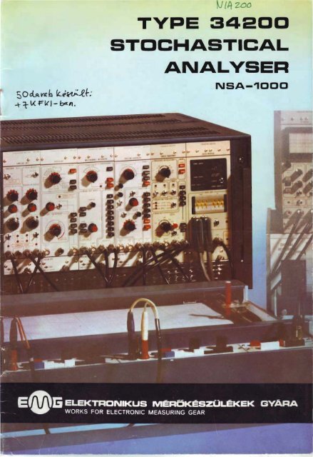
The Type 34 200 STO CHASTICAL ANALYSER ~ /; !'('{ 1 .)<br />
BASIC ASSEM BLY is a universol equipment for j-eV>.(-(<br />
testing rando m signals. Since, however, the r<br />
basic a ssembly will accommodate measuring ~ { ~\.'i~<br />
unit s other than the four basic ones, a new<br />
stochastical analyser is obtained, which offers<br />
a lorger number of facilities. Moreover, throug h<br />
o combination of the additiono l measuring units,<br />
setups optimolly suited to the actual measurement<br />
task will be obtained. The basic assembly<br />
can be used above ali in the follawing functions:<br />
auto-correlation<br />
cross-correlation<br />
cross-correlation (voltage-pulse)<br />
multi-channel signal averaging<br />
pulse rate time distribution<br />
time interval distribution<br />
omplitude distribution<br />
amplitude density<br />
signal mean and rrns values<br />
digital filtering<br />
pseudo-ro n dom sig na l generation<br />
system identification by pseudo-random<br />
sig no ls<br />
continuous manitoring or single onolysis<br />
generotion of digital sine, cosine, sowtooth<br />
sig no ls.<br />
The individuol odditional units will add the follawing<br />
functions to the above ones.<br />
FOURIER TRA SFO M<br />
E-640<br />
FOURIER TRANSFORMER<br />
real or imoginory port of lineor spectrum<br />
outo-power density function<br />
real or imoginory port of cross-power density<br />
function<br />
multiplication with window function (rectangulor,<br />
Honning, Bortlett)<br />
logarithmic Y output, too<br />
PE 3 67<br />
Dl IT L INTE<br />
Z- 75<br />
CE<br />
MONITOR<br />
visual observotion ond value estimation of<br />
input and output signals<br />
oncitlory for hondling ond servicing the peripherals<br />
.. off-crote" functioning (only +5.8 V/3,5 A).<br />
DIGITAL INTERFACE<br />
readout of chonne11 number and channel<br />
content of basic assembly<br />
readout of channel number ond channel<br />
content of Fourier transforrner<br />
continuous data readout within preselected<br />
limits<br />
interface to printer, tope punch, teletype<br />
optional (under development) interface to<br />
Type 666 programmable colculator
The equipment has been designed with the objective<br />
of providing a range of parameters as<br />
wide as possible, enabling many different types<br />
of measurement. The time schole of 100 ns to<br />
1 s, a resolution of about 1 °/ 0 (corresponding to<br />
100 channels), its facility of continuous manitoring<br />
- ali ore valuable features suiting the<br />
equipment to very wide applications in the<br />
measurements of stochastic signals. The equipment<br />
is a signal analyser ernplaying 100 digital<br />
channels, a storage capacity of 20 bits/ channel,<br />
performing aU computations simultaneously<br />
with the measurement. The basic as·<br />
sembly does not include a result display, but<br />
it can be attached to any conventional type of<br />
oscilloscope or XV plotter. Furthermore, the<br />
principel signals can be obtained from connectors.<br />
The resuhs can be read out at any frequene-y<br />
even during the measurement. ln addition<br />
to the conventional integreting-type averaging<br />
(single analysis), "forgetting" type integration<br />
(continuous monitoring) is also feasible. Both<br />
the number of averagings and the " forgetting"<br />
time constant ore variable over a wide range.<br />
The equipment can be used for the onolysis of<br />
continuous signals (AC or DC) and pulses. The<br />
width of its time channels can be selected between<br />
100 ns and 1 s (in correlation modes);<br />
thus it is equally suitable for the investigatien<br />
of very fast and very slow processes. ln amplitude<br />
analyses, the maximum sampling freque n<br />
ey is 5 kHz (otherwise 0.5 M Hz). The f unction<br />
generator provides digitaily generated sin, cos,<br />
pseudo-random and sawtooth sionals with<br />
frequencies adjustable over wide limits. The<br />
time functions of the basic assembly in multichannel<br />
signal averaging and correlation modes<br />
e-an be studied by aid of the Fourier transforrner<br />
in the frequency range, too. For a better<br />
i'llustration, the number of frequency pointscan<br />
be increased. Thus, tagether with the cycle time,<br />
the frequency resolütion can be varied over<br />
wide limits (from 1.25 mHz to 100 kHz). Focil1-<br />
ties ore provided for using time w indows other<br />
then the square-form, vis. multiplication by<br />
Honning and Bartlett weighting function. The<br />
real or the imaginary ports of the functions<br />
within the particulor range can be fo rrned in<br />
succession. Like in the basic a ssembly, the data<br />
outputs deliver analog as weil as d igita l signals<br />
moreover, the analog Y output can be switched<br />
over to logarithmic display, too. The Manitor<br />
unit performs mainly ancillary functions -visual<br />
observation of signals, the estimation of their<br />
values, setting the test setup, facilitating a servicing<br />
and handfing of peripherals (e. g. the use<br />
of Z modulation at peak searching}. Plugged in<br />
alternatively, the M anitor and the D igital Interface<br />
will take over the manitoring function of<br />
the power supply. IM PORTANTI The Manitor is<br />
suitable for "off·crate" functioning, too, only a<br />
power supply of +5,8 V/3,5 A is required. The<br />
Digital Interface enables the variaus functions<br />
(recorded by the basic assembly) and, in expanded<br />
configuration, the frequency spectra<br />
(provided by the Fourier transformer) to be displayed<br />
digitaily or recorded on o tape punch,<br />
o printer or teletype - of course, either for o<br />
given point o r for a ny arbitrary section.<br />
GENERAl SPECIFICATIONS OF THE<br />
BASIC ASSEMBLY<br />
mains data : voltage 220 V ± 10 Ofo<br />
(127 or 110 V by re-connection)<br />
frequency : 50/60 Hz<br />
power consumption: 250 VA<br />
- dimensions: height 316 mm<br />
widttl 505 mm<br />
d epth 600 mm<br />
weight : 36 kg<br />
warm -up time : 15 minutes
o HE IC S E BLV<br />
@<br />
Cabinet<br />
C rate (wi red frame)<br />
Front panel covering two blank ponels<br />
(i<br />
CE,<br />
0<br />
0<br />
Measuring uni ts :<br />
type 34 630 Sam pl ing unit NE-630<br />
type 34 631 1Processor NE-631<br />
type 34 632 Mulii-channel integretor NE-632<br />
type 34 633 Function generator NE-633<br />
IllUllliUl IUlfill IIIIC AlUilU<br />
"" lll·-<br />
+mn<br />
1111 llllllliT<br />
l \<br />
type<br />
®<br />
34 252 Power supply NB-252<br />
®<br />
0<br />
type 34 252/ 111. law-current unit<br />
®<br />
type 34 252/IV. capacitor unit<br />
typE 34 252/ 11. high -current unit<br />
®<br />
@)<br />
®<br />
@<br />
type 34 252/V low-valtage<br />
type 34 252/VI. law-voltage<br />
type 34 252/VII. low-valtage<br />
unit<br />
unit<br />
unit<br />
- type 34 657 Po wer control unit NZ-657<br />
..<br />
®<br />
0®
G<br />
<strong>TYPE</strong> 34630 SAMPLING UNIT NE- 630<br />
. ~<br />
UIPLII5 IIIT<br />
NE830<br />
~ · · c>l<br />
.:> .<br />
OlGITAl OUT<br />
CHACNJ!<br />
HT.P !..Ol<br />
the second 100-channel correlation<br />
can also be recorded by aid of the<br />
computationai delay<br />
function<br />
built-in<br />
~ further (external) delays may be added through<br />
the rear panel connector<br />
(! analog pre-processing: ca libroted ga in and DC<br />
offset (independent at both inputs) ;<br />
selection of the appropriate input channel;<br />
selection of DC, G N D, A C;<br />
overdrive indicatien in compliance with the<br />
+3 V window;<br />
peak detection<br />
4& um<br />
4<br />
HL-level trigger pulse output correspo nding to<br />
the actual mode of triggering, for d riving other<br />
instruments<br />
pseudo-random or sawtooth signal connection<br />
MAIN TECHNICAL DATA<br />
- Input coupling: DC, GND, AC<br />
- Input voltage range : 0.1 to 15 V p-p<br />
- DC offset : ±5 V (resolution 10 mV)<br />
- Max. input voltage: ± 20 Vp<br />
- Input impedance : 100 kohms // 30 pf<br />
- Bandwidth : DC to 1 MHz (-3 dB) or<br />
1 Hz to 1 MHz (-3 dB)<br />
- G ain : in ó steps (with a continuous coverage of 1 :3<br />
within each step)<br />
- Precomputational delay : zero, external, 100 L:,t<br />
- Pulse counting : max. 15/ L:, t (max. 5 M Hz)<br />
- A/D conversion, in channel A: ± 3 V in steps of 200 mV<br />
in channel B': 1 bit (related to the reference<br />
voltage)<br />
- Max. voltage of reference input: ± 5 Vp
<strong>TYPE</strong> 34631 PROCESSOR NE-631<br />
STOCH 'ST ICA L A.NA LY!ER<br />
(NIA IOOOJ<br />
CIOCK<br />
IIIARNING:<br />
H CI. OCK IS<br />
OlY ID EO &T<br />
MoH .2 0 M~ z<br />
UJ CI O C~ l PUT<br />
. ~ o<br />
o<br />
[IMI"t<br />
PUlSfS OU T<br />
RFMIJTE COliT t<br />
12 measuring modes<br />
2 operotion modes<br />
®<br />
a new meosurement cycle may be triggered by<br />
the end of the previcus cycle or by o voltage<br />
level of the input signal or by on externol signol<br />
the red LED is illuminated if a trigger is selected<br />
incansistent with the actual measuring<br />
mode<br />
• SYSTEV MFKI<br />
.,..,,<br />
NAOE IN HO HSA~Y<br />
principel signals (controlling the operotion of<br />
the onalyser). Remete control of trigger ond<br />
measuring modes<br />
®<br />
output used for triggering processes synchronous<br />
with the measuring cycles, for operotion<br />
in the onalyser system<br />
MAIN TECHNICAL DATA<br />
Modes ol measurement<br />
- Auto-correlation: to i n put A or B<br />
- Cross-correlation : input A or B delayed, or B delayed,<br />
pulse A, anologue B<br />
- Multi-channel signal averaging<br />
- Pulse rate time d istribution<br />
- Time intervol distribution<br />
- Amplltude distribution function<br />
- Ampiitude density function<br />
- Sig nal mean value<br />
- Signal rms value<br />
M odes ol operotion<br />
- Cleoring the register contents<br />
- Measurement process<br />
- Data starage (after measurements)<br />
Sompling ol delay eyeles<br />
- ln correlation measurements: 0.1 /Js to s {in 22 steps)<br />
- ln PHA : 0.2 ms to 1 s (in 12 steps)<br />
- ln t he rest of functions : 2 us to 1 s (in 18 steps)<br />
Clock pulse: 10 MHz (accurocy, ± to-lt, at +25°C)
<strong>TYPE</strong> 34632 MULTI-CHANNEL INTEORATOR NE-632<br />
CD<br />
from the attainment of the averaging number<br />
selected, the red LED is illuminated (i. e. indicating<br />
the campletion af the measurement or<br />
the beginning of the formatien of on uncolibroted<br />
result)<br />
generation of + 40 V norrow pulses for each<br />
channel (or far every 100 chonnels) for the monitor<br />
or oscilloscopes<br />
0)<br />
the integretor may also be operated from on<br />
external digital source, thus e. g. o digital filtering<br />
con be realized in exponentiol averaging<br />
&Oa unt<br />
M~Df IH HUNU~Y<br />
MAIN TECHNICAL DATA<br />
M odes of operot ion<br />
- Exponential averaging<br />
(the ,.forgetting" time canstal)t depend s on the m'Ode<br />
of measurement ond the sampli ng or delay cycle)<br />
- linear averaging with preset display<br />
- linear averoging, w ith o utomotic stopping upon ottoinment<br />
of o p reset value<br />
Number of o veragings: 2K where K = 4, 6, 8, 10, 12, 13,<br />
14, 15,<br />
Data outputs<br />
- Output X (channel number) : 7 bits binory and ± 3 V<br />
analog<br />
- Output Y (channel content : 20 bits binary (with sig n),<br />
± 3 V analog (the 7-bit portion of the 20 bits<br />
te be read out can be selected in 8 steps for<br />
the D/A converter)<br />
Readout modes<br />
- For each channel, w ith manual Iriggering<br />
- Fast readout, e. g. for oscilloscope<br />
- Slow readout, e. g. for XV platter (0.2 Ht to 10 Hz)<br />
- Slow readout from external clock pulse
<strong>TYPE</strong> 34633 FUNCTION GENERATOR NE-633<br />
FUNCI IDN<br />
lElEIATil<br />
ti.:<br />
o . -<br />
LJ<br />
o<br />
It<br />
o<br />
(-)<br />
OlGilAl lll<br />
•O<br />
G) providing signols in step with the repetition of<br />
o pseudo-rondom signal<br />
@ the binory output may provide signal trains re•<br />
turning or not returning to zero<br />
0 in the case of coding or decoding, it will provide<br />
o signal if a ditference is found between<br />
the initici word and the coded one<br />
⩔ neu<br />
lo
u<br />
<strong>TYPE</strong> 34640 FOURIER TRANSFORMER NE-640<br />
.SJO(II.A.$'f1Cll AMAlfi El<br />
't' OUf<br />
u r tLO t<br />
..<br />
10<br />
the data loading and camputation processes<br />
can be started by a · toggle switch except<br />
when the automatic method is applied<br />
®<br />
the weighting function is generated by the<br />
Function Generator (the Fourier t ransfarmer<br />
providing the clock pulse only)<br />
any quarter of the transforrned function can be<br />
magnified by varying the display sensitivity<br />
4<br />
the readout cycle is slow (here fixed<br />
manual or external, similor to the<br />
sem b ly<br />
®<br />
1 Hz), fast,<br />
basic ossimilor<br />
to the Multi-channel lntegrotor, the 8-bit<br />
part of the 20 bits to be read out can be selected<br />
in 4 steps for the output D/ A converter<br />
MAIN TECHNICAL DATA<br />
- M öde: real or imaginary part of spectrum<br />
- N umber of f requency' points: 50, 100, 200, 400 where<br />
the respective frequency resolutions ore L,f, /:::,.f/ 2,<br />
/::,f/4, l:,f/8 (l:,f= 1/100l:,t)<br />
- Frequency range : DC to 5 MHz<br />
- Weighting window : rectang ular, cosine (Honning) ond<br />
Bartlett<br />
- Input data loading : manual or outomotic<br />
- Data output: analog X, lin Y or X, log Y<br />
d igital X, Y (in binary code)
<strong>TYPE</strong> 34641 CRT MONITOR NE-641<br />
STt:rCH4 llf l ~HÁLY Ifi<br />
in ,.off-crate" operation, the connector can be<br />
driven by o power supply of + 5.8 V source<br />
voltage (providing 3.5 A)<br />
input sensitivity controls matched to the basic<br />
assembly<br />
LED takes over the function of the power control<br />
unit (blinking at about 1 Hz to indicate the<br />
failure of any one of the supply voltages)<br />
switch, for switching the Manitor on or off, separately<br />
MAIN tECHNJCAL DATA<br />
- Input coupling: DC, GND, AC<br />
- Sensitivity: 2, 1, 0.5 V/div.<br />
- Input impedonce : 100 kohms ll 30 pF<br />
- Max. i n put voltage: 63 V<br />
- Bandwidth: DC or 0.3 Hz to 1 MHz (-3 dB), for X<br />
omplifier<br />
DC or 0.3 Hz to 1.5 MHz (-3 dB), for Y<br />
omplifier<br />
- Z medulotion (with AC coupling) : min. +s V<br />
max. + 4o V
<strong>TYPE</strong> 34675 DIGITAL INTERFACE NZ-675<br />
STOCMAS tiC&l att.\ l TUR<br />
DIGITU liTERrACE<br />
NE-875 l<br />
Q) the place of the first p. c. board is blank for<br />
· the option<br />
the data ore receíved from the Multi-channel<br />
Integretor and the Fourier transforrner through<br />
four 20-pole connectors<br />
triggering or stopping of readout by a toggle<br />
switch<br />
unblanking signal output for the monitor<br />
34 675<br />
IN HUNGARY<br />
@ LED takes over the function of the power control<br />
unit (blinking at about 1 Hz to indicate the<br />
failure of any one of the supply voltages)<br />
MAIN TECHNICAL DATA<br />
- Function: displaying the function values of the basic<br />
assembly or the Fourier tronsförmer<br />
- Channel volue indication: sign + 4 digils (decima!)<br />
ond a 2 diglt exponent (wlth sign) of o blnary base<br />
- Display of channel number : 3 d igils<br />
- Channel number selection: by 2x3-digit thumbwheel<br />
switches (initio! and final volues)<br />
- Peripheral interfoces<br />
tope punch :<br />
T-105 Model (mgde in Polond), MOM EC 7191-01<br />
(EP 36) or 4070 Focit (with selector)<br />
code: 8-bit ASCII, porollel data transfer<br />
teletype:<br />
ASR, KSR, RO (Data Dynamics),<br />
GPO or V- 24 interface<br />
code: 8-bit ASCII, se ri ol data transfer<br />
p rinter :<br />
TR-1872 (type 14892)<br />
code : ASCII reduced to 6 bits, porollel data transfer<br />
- Optional (under development) Interface to the type 666<br />
programmable colculator; with this facility incorporated,<br />
the remete control functlons of the basic assembly,<br />
the Fourier t ransforrner ond the Digital interface<br />
os weil os the control functions of data delivery<br />
will be perforrned by the calculotor.
CIPAL D TA OF OTH<br />
U TS<br />
<strong>TYPE</strong> 34252 PO WER SUPPL V<br />
NB-252<br />
Nominal output voltoges and current s:<br />
+40 V/70 mA<br />
+ 15 V/0.5 A<br />
+ 12 V/0.5 A<br />
-12 V/0.9 A<br />
+ 5.8 V/16 A<br />
- 6 V/0.5 A<br />
<strong>TYPE</strong> 34657 POWER CONTROL UNIT<br />
N Z-657<br />
ln the event of a breakdown of + 5.8 V, + 15 V,<br />
+ 12 V, -6 V stabilized and +40 V unstobilized<br />
voltoges, it will deliver a blinking signal of obout<br />
1 Hz.<br />
<strong>TYPE</strong> 34604 SERVICE UNIT<br />
NE-604<br />
It enables the measuring units to be operated<br />
" off-crote".<br />
EQUIPMENT RECOMMENDED FOR PERIPHERALS<br />
<strong>TYPE</strong> 14892 PRINTER TR-1892<br />
Printing rate:<br />
· Column copocity:<br />
Set of characters :<br />
Data input:<br />
1 line/s (asynchronous)<br />
20<br />
64 different c haracters<br />
(7-bit ISO code reduced to<br />
6 bits)<br />
parallel BCD coded, TTL level<br />
positive logic<br />
<strong>TYPE</strong> 79812 X-Y RECORDER NE-240<br />
Se nsitivity:<br />
Applicoble chart size:<br />
20 mV/cm to 10 V/cm<br />
297x420 mm (A/3 format)<br />
Possthrough speed (average): min. 50 cm/s<br />
Controllable pen lift
<strong>TYPE</strong> <strong>34200</strong> ASS EMB lES OF THE <strong>STOCHASTICAL</strong> ANAL YSER<br />
AND ITS ADDITIONAL UNITS NSA- 1000<br />
Th e un1versal character of<br />
t he measurement system may<br />
be considered frorT' two aspects.<br />
Th e basic assembly<br />
!one is suitable f or a wid e<br />
v ri e ty of measurements;<br />
t he combinations ot t he a d<br />
ditio nal measu ring llnlts<br />
will furt her Increc se the<br />
number of setups fo r different<br />
p u rposes. 10 dlfferent<br />
setups o re available, six of<br />
which o re totolly self-conta<br />
ined, the rest assuming<br />
the use of an external power<br />
sourc e.<br />
<strong>TYPE</strong> <strong>34200</strong><br />
Conti nuous manitoring of the tests<br />
provid ed by the basic o sembly he<br />
manitor involves lower costs t hon the<br />
permanent use of o generai-purpose<br />
oscilloscope.<br />
<strong>TYPE</strong> 34640<br />
<strong>TYPE</strong> 34640<br />
(-0<br />
It ca n be used<br />
for the invest!-<br />
g ation of fu netions<br />
in the<br />
time domain<br />
over the f requency<br />
range.<br />
There ore special<br />
means (e<br />
g. ascilloscope)<br />
provided for<br />
displaying the<br />
output f unctions.<br />
For the tests provided by the basic a ssembly, but<br />
the resu lts may be led to o printer, o tope punch<br />
or teletype.<br />
r - - - -~<br />
:<br />
l<br />
l<br />
.......__...;;;..__ <strong>TYPE</strong><br />
l l 34641<br />
1-----.J ffi<br />
The above setup is completed with<br />
o n external manitor powe red from an<br />
external power supply C+ S.B V/ 3.5A)
<strong>TYPE</strong> 34641<br />
®<br />
-----,<br />
l<br />
l<br />
-- _<br />
For continuous monitoring. For the<br />
..<br />
combined manitoring of a 100-channel<br />
auto-correlation function and<br />
power density function.<br />
l<br />
l<br />
l<br />
l<br />
'--<br />
l<br />
l<br />
- ..l<br />
An optimum setup<br />
with two external<br />
monitors.<br />
<strong>TYPE</strong> 34641<br />
@<br />
monitoring.<br />
An optimum setup provided a general-purpose<br />
oscilloscope and peripherals<br />
ore available.<br />
An optimum<br />
external monitor.<br />
setup with an<br />
EB<br />
PERIPHERALS<br />
PERIPHERALS<br />
Ci)
10<br />
The principel operotion modes of the equípment<br />
are the generation of correlation functions,<br />
línear or exponentíal averaging thereof<br />
and the investigatien of their behavíour wíthín<br />
the gíven domain. The analyser generates digitaily<br />
a relay correlation functíon, substituting an<br />
i -bit bínary word for the signal coming through<br />
one measuring channel ín the samplíng time<br />
ínstants (substitutíng a 5-bit binary word for<br />
the signal coming through the other measuring<br />
channel). The 1-bít manitoring is made wíth respect<br />
to a pseudo-random auxílíary signa l {also<br />
called .,dither" ). The way of sampling varies<br />
wíth the delay cycle time.<br />
.. t<br />
x(t)<br />
y(t) L__,S,_b",i_,_,_ ts _ _ _ _____, l ~b i t multipl i e r<br />
Sym metrical sampling (SS) in slow modes J<br />
,<br />
'~!<br />
i -bit multlplier<br />
Botch sornpling (BS) in medium-rate modes<br />
l -bit register 1 bit reg ister<br />
x(t)<br />
1-bit<br />
multiplier<br />
Shift sampling (ShS) in fastest modes.<br />
J
ln addition to linear averaging, the other averaging<br />
procedure applied by the analyser enables<br />
the process parameter under test to be studied<br />
continuously over a long period of time. The<br />
exponential .,forgetting" typical of the analogue<br />
RC complex, may be written with the help of<br />
the follawing digital arithmetic procedure:<br />
x. +<br />
l ~<br />
Subtroctor<br />
-~<br />
f ...<br />
1<br />
2K<br />
'r!<br />
Adde r<br />
1 ..<br />
1 Register 1--<br />
Black diogram of exponentiol overogíng, K=4 through 15<br />
r<br />
ln the memory of the basic assembly, the result<br />
function is represented by a function sector<br />
consisting of 100 digital samples. ln the course<br />
of the transformation to be carried out, the initio!<br />
signal is regarded to be the periodic repetition<br />
of that sector: the Fourier series of the<br />
signal is generated. The actual frequency resolutien<br />
to be obtained is equal to be reciprocal<br />
of cycle time; the highest actual frequency ls,<br />
as a rule, a hundred times thereof. To better<br />
illustrate the result of transformation, the<br />
number of frequency points may be selected to<br />
be greater, too.<br />
function<br />
to be transformed<br />
o cosine<br />
multipller function<br />
( 2n) cos N n · m<br />
T = 1\ L t<br />
-----,!'<br />
weighting function<br />
Of N sampled values, M=N/2 freq uency points<br />
can be obtained. The m-th real or imaginary<br />
frequency component can be obtained from the<br />
follawing formulae:<br />
N-1<br />
Am= .2 xlnl)· w(nl)· cos l:._l_l) n·m<br />
n= O \ N N N
Responsible publisher: director-general József Kiss lovárt<br />
Editor : László Csé p e<br />
Magyar Hirdetó - Nyomda Zolaegerszeg 79 1287<br />
Manufactured by:<br />
ELEKTRONIKUS M~RÖKÉSZULÉKEK GYARA<br />
WORKS FOR ELECTRONIC MEASURING GEAR<br />
H-1163 Budapest, Cziróky u. 26-32.<br />
Telex : 22-4535<br />
Exported by:<br />
METRIMPEX<br />
HUNGARIAN FOREIGN TRADING COMPANY<br />
FOR INSTRUMENTS<br />
H-1391 Budapest, P.O.B. 202.<br />
Cable: INSTRUMENT, Budapest, HUNGARY