6 Planetary Mixers - Herbst Planetary Mixer
6 Planetary Mixers - Herbst Planetary Mixer
6 Planetary Mixers - Herbst Planetary Mixer

Create successful ePaper yourself
Turn your PDF publications into a flip-book with our unique Google optimized e-Paper software.
6 <strong>Planetary</strong> <strong><strong>Mixer</strong>s</strong><br />
6.1 Review<br />
6 <strong>Planetary</strong> <strong><strong>Mixer</strong>s</strong> 68<br />
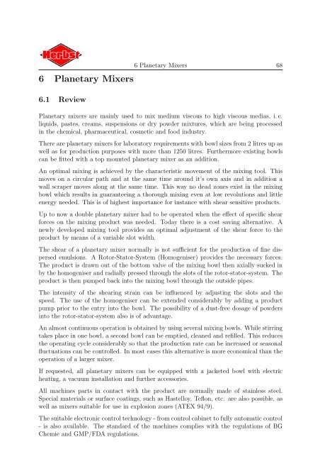
<strong>Planetary</strong> mixers are mainly used to mix medium viscous to high viscous medias, i. e.<br />
liquids, pastes, creams, suspensions or dry powder mixtures, which are being processed<br />
in the chemical, pharmaceutical, cosmetic and food industry.<br />
There are planetary mixers for laboratory requirements with bowl sizes from 2 litres up as<br />
well as for production purposes with more than 1250 litres. Furthermore existing bowls<br />
can be fitted with a top mounted planetary mixer as an addition.<br />
An optimal mixing is achieved by the characteristic movement of the mixing tool. This<br />
moves on a circular path and at the same time around it’s own axis and in addition a<br />
wall scraper moves along at the same time. This way no dead zones exist in the mixing<br />
bowl which results in guaranteeing a thorough mixing even at low revolutions and little<br />
energy needed. This is of highest importance for instance with shear sensitive products.<br />
Up to now a double planetary mixer had to be operated when the effect of specific shear<br />
forces on the mixing product was needed. Today there is a cost saving alternative. A<br />
newly developed mixing tool provides an optimal adjustment of the shear force to the<br />
product by means of a variable slot width.<br />
The shear of a planetary mixer normally is not sufficient for the production of fine dispersed<br />
emulsions. A Rotor-Stator-System (Homogeniser) provides the necessary forces.<br />
The product is drawn out of the bottom valve of the mixing bowl then axially sucked in<br />
by the homogeniser and radially pressed through the slots of the rotor-stator-system. The<br />
product is then pumped back into the mixing bowl through the outside pipes.<br />
The intensity of the shearing strain can be influenced by adjusting the slots and the<br />
speed. The use of the homogeniser can be extended considerably by adding a product<br />
pump prior to the entry into the bowl. The possibility of a dust-free dosage of powders<br />
into the rotor-stator-system also is of advantage.<br />
An almost continuous operation is obtained by using several mixing bowls. While stirring<br />
takes place in one bowl, a second bowl can be emptied, cleaned and refilled. This reduces<br />
the operating cycle considerably so that the production rate can be increased or seasonal<br />
fluctuations can be controlled. In most cases this alternative is more economical than the<br />
operation of a larger mixer.<br />
If requested, all planetary mixers can be equipped with a jacketed bowl with electric<br />
heating, a vacuum installation and further accessories.<br />
All machines parts in contact with the product are normally made of stainless steel.<br />
Special materials or surface coatings, such as Hastelloy, Teflon, etc. are also possible, as<br />
well as mixers suitable for use in explosion zones (ATEX 94/9).<br />
The suitable electronic control technology - from control cabinet to fully automatic control<br />
- is also available. The standard of the machines complies with the regulations of BG<br />
Chemie and GMP/FDA regulations.
6.2 Construction Types<br />
6.2 Construction Types 69<br />
One differentiates between three different models, up-right support construction, stand<br />
construction and the planetary mixer with hydraulic lifting column.<br />
Figure 45 shows the planetary mixer in it’s classic tripod construction. A normal bowl<br />
capacity ranges from 7 to 120 litres. A typical aspect is that the bowl can be moved up<br />
and down whereas the mixing head with the drive is stationary.<br />
Figure 45: Vacuum <strong>Planetary</strong> <strong>Mixer</strong> HRV 50 in up-right support construction<br />
With regard to the stand construction of the mixer it is possible to move the main drive<br />
unit, which consists of the bowl cover, the stirrer drive and the stirrer devices, up and<br />
down. As a rule the bowls are fitted with rollers; sometimes they are equipped with<br />
suitable lashes for fork lift trucks. There are three alternatives with stand mixers: the<br />
wall stand, the floor stand and the mobile stand. Figure 46 shows the planetary stirrer<br />
with wall fixing.<br />
Figure 47 shows a 120 litres planetary mixer combined with a rotor-stator-system (Homogeniser).<br />
This new construction is available for a bowl capacity of 100 to appr. 1500<br />
litres.<br />
The lifting column of the mixer which lifts the complete head with drive and stirrer tools<br />
hydraulically represents a new development. Disadvantages of a folded coat respectively<br />
grease lubrication are being avoided by a dry running lifting column. A specially simple
6.2 Construction Types 70<br />
Figure 46: <strong>Planetary</strong> <strong>Mixer</strong> HRV-S 120 in stand construction<br />
Figure 47: <strong>Planetary</strong> <strong>Mixer</strong> HRV-K 120 HO with hydraulic lifting column
6.2 Construction Types 71<br />
and effective cleaning of the complete mixer is possible in combination with the smooth<br />
stainless steel surface of the machine housing. It stands to reason that also the mixing<br />
space which has contact with the product as well as the stirring tools are constructed<br />
”easy-to-clean”. After lifting the drive head the bowl, which is fitted with rollers, can be<br />
moved to other parts of the site.<br />
These two construction types are being used specially with larger bowl capacities because<br />
the bowl does not need lifting.<br />
6.2.1 Product Models HR-S 2 to HR 10<br />
The planetary mixers HR-S 2 to HR 10 are designed for use in laboratories and small<br />
production runs. The effective mixing volume lies approx.. between 0,4 and 1,6 litres for<br />
the planetary mixer HR-S 2 and between 2,0 and 8,0 litres for the planetary mixer HR<br />
10.<br />
The stainless steel mixing bowl of the planetary mixer HR-S 2 (see Figure 48) is either<br />
single or double jacketed with a volume of 2 litres. By using a glass mixing bowl, the<br />
mixing process can be viewed through the glass jackets which is especially advantageous<br />
in the research and development field.<br />
Figure 48: <strong>Planetary</strong> <strong>Mixer</strong> HR-S 2<br />
a) stainless steel mixing bowl, b) glass mixing bowl<br />
The driving unit with the planetary gear is fixed on top of the mixing bowl cover. The level<br />
adjustment of the cover is manual; for weight equalisation purposes a counter weight is<br />
installed on the inside of the column. Alternatively the level adjustment can be regulated<br />
electrically by a linear drive.
6.2 Construction Types 72<br />
Starting with the large planetary mixing unit, all known standard mixing tools can be<br />
used for stirring purposes; complete with a wall scraper made of Polyamide, Teflon or<br />
stainless steel.<br />
A double jacketed bowl can be cooled respectively heated by an external system. The<br />
unit can also be equipped for vacuum operation.<br />
The support column, floor plate and all parts in contact with the product, with the<br />
exception of the scraper, are of stainless steel construction. The bowl cover and the drive<br />
unit are, for weight reasons, made of aluminium.<br />
Figure 49 shows a 7 litre vacuum planetary mixer unit HRV 7. The bowl is fixed to the<br />
Figure 49: Vacuum <strong>Planetary</strong> <strong>Mixer</strong> HRV 7<br />
vacuum cover by means of a bayonet lock. An illuminated sight glass fitted with a wiper<br />
permits observation of the mixing process.<br />
An especially user friendly design of a stand construction is shown in figure 50. The double<br />
jacketed, electrically heated, bowl is fitted onto the stand base plate. The complete mixing<br />
head can easily be manually lifted by means of the guides fitted with ball bearing and<br />
a counter weight in the stand column. A hydraulic, electrical or pneumatically operated<br />
level adjustment can also be provided. Figure 63 on page 84 shows a 3 litre vacuumplanetary<br />
mixing unit with an electric level control.<br />
The 7 litres planetary mixer is fitted with a protection hood. The speed is controlled by<br />
a mechanical control gear and not by a frequency transformer.<br />
A customised basis standard version of the mixers – as illustrated in figure 51 – can be<br />
fitted onto a mobile stainless steel trolley together with a 2 ltrs. vacuum planetary mixer<br />
and an external heating/cooling system.
6.2 Construction Types 73<br />
Figure 50: <strong>Planetary</strong> <strong>Mixer</strong> HR-S 7<br />
Figure 51: Vacuum Mixing Plant HRV-S 2
6.2.2 Product Models HR 15 to HR 120<br />
6.2 Construction Types 74<br />
These planetary mixers are designed foremost for use in production units, but are also<br />
suitable as laboratory units. The available mixing capacity is between approx. 3 and<br />
100 litres. These mixers can be constructed as classic stand version or the more versatile<br />
stand model. Figure 27 shows a 15 l vacuum planetary mixer with homogeniser HRV 15<br />
HO as a classic version. Figures 45 to 47 show design variations.<br />
Figure 52: Vacuum <strong>Planetary</strong> <strong>Mixer</strong> with Homogeniser HRV 15 HO<br />
6.2.3 Product Models HR-S 100 to HR-S 1250<br />
These planetary mixers are designed foremost for use in production units. The available<br />
mixing volume varies between approx. 20 to 1000 litres. These mixers are designed as<br />
free standing mixer units, but are also optionally available as wall or floor mounted units.<br />
The free standing version with an integrated lifting column and a mixing bowl volume of<br />
up to 500 litres is also available.<br />
Figure 53 shows a free standing planetary mixer. The complete drive unit is electrohydraulically<br />
lifted to permit the removal of the mixing bowl after termination of the<br />
mixing process.
6.3 Customised Designs 75<br />
Figure 53: <strong>Planetary</strong> <strong>Mixer</strong> HR-S 400 (stand construction)<br />
6.3 Customised Designs<br />
6.3.1 Double <strong>Planetary</strong> <strong>Mixer</strong><br />
Where higher shear force entry is required in the mixing process, a special mixing tool<br />
(see also chapter 6.4.4) or a double planetary mixer can be used. The special design and<br />
position of the two mixing tools provide the necessary shear forces for a free revolution<br />
and an effective mixing operation. The level of the shearing strain is dependent upon the<br />
rotating velocity and the clearances between the mixing tools.<br />
6.3.2 Detachable <strong>Planetary</strong> <strong>Mixer</strong><br />
Suitable bowls can be retrofitted with a detachable planetary mixer. The planetary mixer<br />
unit would then be attached to the centrally located bowl flange.<br />
6.3.3 A Combination of a <strong>Planetary</strong> and a Central Mixing Unit<br />
In the research and development field it is often of great importance to cover the largest<br />
possible functional range with only one mixer. To achieve this the planetary mixer can<br />
be fitted with an additional connection for a central agitator shaft.<br />
Figure 54 shows a combination of a planetary gear with a central agitator shaft. On the<br />
left is the planetary gear with the planetary mixing tool and wall scraper, the centrally<br />
located drive spigot for the agitator is clearly visible.
6.4 Machine Technique 76<br />
Figure 54: <strong>Planetary</strong> Gear with Connection Provision for a Central Agitator Shaft<br />
The Figure on the right shows the same planetary gear unit with a connected central<br />
agitator shaft. A high-speed dissolver plate serves as mixing device.<br />
The machines in the following illustration were designed for colour pigment operation<br />
in the printing industry. The left one shows the operating mode of a central mixer.<br />
The agitator shaft, dissolver plate and the pulled down mixing bowl supports are clearly<br />
visible. The bowl is fixed by means of a tension strap (not visible in the illustration).<br />
On the right is the same mixing unit, however, converted for the operation as planetary<br />
mixer. The bowl fitting is pulled up and a 40 litre bowl is fixed therein. The matching<br />
bowl carriage holds the smaller 15 litre bowl which can also be operated by this planetary<br />
mixer by merely exchanging the mixing device and the wall scraper.<br />
Low as well as high viscose products can be processed in this mixing unit.<br />
6.4 Machine Technique<br />
6.4.1 <strong>Planetary</strong> Gear<br />
The characteristic movement of the planetary mixing tool is provided by the planetary<br />
gear. The movement course of a specific point of the mixing tool can be seen in figure 56.<br />
Construction of a planetary gear is shown in figure 57.<br />
The rotating shaft is sealed by means of radial seal rings. For special duties additional<br />
O-rings can be provided for gearbox seals.<br />
6.4.2 Totally enclosed <strong>Planetary</strong> Gear<br />
The new planetary gear is designed specifically for use in contamination sensitive areas<br />
such as Pharmaceutical, Food and Cosmetic industries.
6.4 Machine Technique 77<br />
Figure 55: <strong>Planetary</strong> <strong>Mixer</strong> with additional Central Agitator Shaft HR-S 15-40 Z<br />
Figure 56: Plotted point of a <strong>Planetary</strong> Mixing Tool
6.4 Machine Technique 78<br />
Figure 57: Construction of <strong>Planetary</strong> Gear<br />
The standard design does not provide an absolute separation between the product area<br />
and the transmission interior (see fig. 57). This disadvantage is eliminated by the total<br />
encapsulation of the planetary gear. Total enclosure is ensured by the installation of<br />
standard seals (see also centrally mounted mixers) or the use of slip rings. The use of<br />
quick-release couplings allows for a quick and trouble free exchange of the various mixing<br />
tools.<br />
6.4.3 Equipment Design<br />
<strong>Planetary</strong> mixers are normally fitted with a variable speed adjustment. The speed adjustment<br />
can either be reached by a frequency converter or a mechanical variable speed<br />
gear box.<br />
The level of the mixing bowl for stand mounted planetary mixers is normally adjusted<br />
hydraulically, however, a number of mixer types have the possibility of a hand or foot<br />
operated hydraulic adjustment.<br />
The mixer bowl and the planetary mixer head are built as a correlated unit to ensure the<br />
correct all clearance between mixing bowl, mixing tool and wall scraper. The scrapers<br />
are usually of either Polyamide or Teflon and are pressed onto the bowl jacket by the<br />
product during the mixing process, thus preventing product adhesion. A stainless steel<br />
scraper can be supplied but this requires a manual adjustment to provide the necessary<br />
wall clearance.
6.4 Machine Technique 79<br />
Single or double jacketed bowls can be supplied. Jacketed bowls are usually fitted with<br />
electrical heating elements which heat the transfer medium (water or thermo-oils). The<br />
temperature is controlled by a thermostat. By operating temperatures above 60 ◦ C<br />
additional insulation around the mixing bowl must be fitted. Operating temperatures of<br />
above 90 ◦ C and up to above 200 ◦ C require a thermo-oil as heating medium. External<br />
heating/cooling unites or steam heating, complete with the necessary safety precautions,<br />
may also be used.<br />
It is recommendable to install an additional heating/cooling coil in the jacket should it<br />
be necessary to heat or cool the product during mixing.<br />
The temperature indication of the vessel jacket does not present a problem, however, the<br />
product temperature indication is a different matter. There are a number of possibilities,<br />
i. e. the temperature element may be fitted into a tube which penetrates the inside jacket<br />
of the bowl, or is extended into the bowl which then requires the wall scraper to be cut<br />
out to the extent of the thermometer.<br />
In case of planetary mixers with homogeniser the temperature element may be mounted<br />
inside the bottom discharge of the mixing bowl as the total product is circulated during<br />
the homogenising operation.<br />
Both described mounting methods have accuracy problems. Should correct product temperature<br />
control during the mixing operation be essential then the installation of a temperature<br />
element on the mixing tool itself is the optimal method as the measurement<br />
values are transferred by infrared technology; alternatively a slip ring transmitter with<br />
higher temperatures can be installed (see section 3.5.2, page 24).<br />
6.4.4 Mixing Tools<br />
Figure 58 shows some standard planetary mixing tools.<br />
The fitting of a quick release coupling allows for a trouble-free change of mixing tools to<br />
suit the specific need of various products.<br />
Figure 58: Standard <strong>Planetary</strong> Mixing Tools<br />
Form F1 is often used to stir creams, ointments and pastes, F2 for light substances, F3 for<br />
solid substances and powder mixtures. Form F4 is used to process emulsions and foams.
6.4 Machine Technique 80<br />
The stirring tool F4 is also applicable for a double planetary mixer and so is F5, which<br />
can be used for solid and viscous products.<br />
The straight-arm paddle agitator F5 can be combined with the shearing frame F5.1.<br />
This frame is fixed to the mounting support for the scraper. The stirring tool will comb<br />
through this shearing frame at every revolution. The result can be compared to the<br />
one of a double planetary mixer, whereas the relative speed between the stirring tool<br />
bars is lower. The value of the transferable shear forces depends also on the fixed slot<br />
width and the revolutions, and this money saving alternative is mostly sufficient for many<br />
applications.<br />
The planetary stirring tool F6 is specially suitable for stirring oil-in-water-emulsions.<br />
Specific designs can also be provided in addition to the standard mixing tools application.<br />
Figure 59 shows a helical stirrer.<br />
Figure 59: Helical <strong>Planetary</strong> Mixing Tool
6.5 Application Examples<br />
6.5 Application Examples 81<br />
6.5.1 Vacuum Laboratory Mixing Unit HRV-S 2-ex<br />
A further development of the vacuum mixing unit HRV-S 2 (figure 51) is illustrated in<br />
Figure 60. The mixing unit is housed in a stainless steel cabin with two wing doors. The<br />
Figure 60: Vacuum Laboratory Mixing Unit HRV-S 2-ex<br />
cabinet of the Ex-zone 1 construction is located in a non Ex-proof area. Operation of<br />
the mixing unit is only possible with doors closed. The large glass windows in the doors<br />
enable a perfect sight of the mixing process inside. The cabin interior is vented by an<br />
external exhausting system in order to remove solvent vapours.<br />
The vacuum pump, the circulation thermostat and the main control box as well as the<br />
control panel are located outside of the cabinet.<br />
The special construction of the mixing unit permits the selective operation of the highspeed<br />
central mixer or the low speed planetary mixer. The fitted guide rail allows for<br />
horizontal movement of both mixing units. The integrated counterweight permits an easy<br />
vertical movement of the mixer driving gears.
6.5 Application Examples 82<br />
In addition, the mixing unit is fitted with a simple bowl discharge device. The build-in<br />
discharge aid, shown on the right side ofFigure51, which is manually operated by means of<br />
a threaded spindle. This discharge aid permits the product paste to be discharged directly<br />
from the mixing bowl into a double chamber cartridge for which a special acceptance<br />
device has been integrated.<br />
6.5.2 Vacuum-Double-<strong>Planetary</strong> Mixing Unit HRV-S 2 DP<br />
Figure 61 shows the Vacuum-Double-<strong>Planetary</strong> Mixing Unit HRV-S 2 DP used in the<br />
production of dental compounds.<br />
The elevation adjustment of the mixing heard by manual means is assisted by the installation<br />
of a counter weight housed in the support column and the carriage is mounted on<br />
ball bearings.<br />
Figure 61: Vacuum-Double-<strong>Planetary</strong> Mixing Unit HRV-S 2 DP<br />
Employed are intertwine operating mixing tools of a straight-arm agitator design. All<br />
parts as well as the internal jacket of the bowl, which are exposed to the product, are<br />
coated with polyamide.
6.5 Application Examples 83<br />
6.5.3 Vacuum Double <strong>Planetary</strong> <strong>Mixer</strong> HRV-S 2-4 DP<br />
The planetary mixing unit shown below in figure 62 is fitted with a double jacket glass<br />
bowl. This bowl enables the product to be cooled with water and allows easy observation<br />
Figure 62: Vacuum Double <strong>Planetary</strong> <strong>Mixer</strong> HRV-S 2-4 DP<br />
of the mixing process, ideally suited for development work.<br />
The possible use of two different bowl sizes allows for a wider range of applications.<br />
6.5.4 Vacuum <strong>Planetary</strong> <strong>Mixer</strong> HRV-S 3<br />
The vacuum planetary mixer, shown in figure 663, is used in the process development of<br />
new tooth past recipes and in trial operation. The stainless steel bowl, which is mounted<br />
on the base plate of the stand, has a volume varying between. 0,6 to 2,4 litres. An<br />
electrically driven linear gear is installed to control the level adjustment of the machine<br />
head.<br />
6.5.5 Vacuum-Planatary <strong>Mixer</strong> HRV-S 7<br />
The Vacuum-<strong>Planetary</strong> <strong>Mixer</strong> in image 64 is used for the production of gels. The single
6.5 Application Examples 84<br />
Figure 63: Vacuum <strong>Planetary</strong> <strong>Mixer</strong> HRV-S 3<br />
Figure 64: Vacuum-Planatary <strong>Mixer</strong> HRV-S 7
6.5 Application Examples 85<br />
jacket bowl is fixed on the stand floor plate. The level adjustment of the machine head is<br />
manual. The mixing process can be observed through a sight glass.<br />
The machine cover is designed for the operation with different bowl sizes, whereby only<br />
the mixing tools and the bowl scraper have to be exchanged.<br />
6.5.6 <strong>Planetary</strong> <strong>Mixer</strong> HR-S 25<br />
Figure 65 shows the stand version of a basic planetary mixer. The 25-liter bowl is fitted<br />
Figure 65: <strong>Planetary</strong> <strong>Mixer</strong> HR-S 25<br />
with a trolley. The height of the machine is manually adjustable.<br />
6.5.7 Vacuum Double <strong>Planetary</strong> <strong>Mixer</strong> HRV-K 30 DP<br />
The characteristics of the planetary mixer (figure 66) show the two separate drive units,<br />
which allow the operation of the slow rotating planetary stirrer without being dependent<br />
on the high-speed dissolver. The two drive units have an independent variable speed<br />
adjustment, as required by the product mix.
6.5 Application Examples 86<br />
Figure 66: Vacuum Double <strong>Planetary</strong> <strong>Mixer</strong> HRV-K 30 DP<br />
If selective high shear forces are required for a product mix, these can be provided by a<br />
dissolver. The planetary mixing tool provides well blended product mixes even at highest<br />
viscosity.<br />
The insulated jacket bowl is fitted with a screw-mounted electric heating element for the<br />
heating media; with water as heating medium a product temperature of 90 ◦ C can be<br />
realized. A vacuum pump for vacuum operation is provided.<br />
The complete mixing unit is designed for easy cleaning. Cables are installed in one of the<br />
two lifting columns.<br />
6.5.8 Vacuum Double <strong>Planetary</strong> <strong>Mixer</strong> HRV 40-60 DP<br />
A double planetary mixing unit is shown in figure 67.<br />
This unit is intended for mixers fitted with 40 or 60 litre mixing bowls. The two mixing<br />
tools interlace with each other, whereby the straight arm model (form F5) also provides<br />
an upwards flow of the product. In addition a wall scraper is fitted which moves the<br />
product from the jacket to the centre of the bowl.<br />
The planetary mixer is used for the production of highly viscose pastes.
6.5 Application Examples 87<br />
Figure 67: Vacuum Double <strong>Planetary</strong> <strong>Mixer</strong> HRV 40-60 DP<br />
6.5.9 <strong>Planetary</strong> <strong>Mixer</strong> HR-S 100<br />
The planetary mixer show in Figure 68 is used in the manufacture of abrasive products,<br />
i e. mixing of powdery raw material with binding agents and hardeners.<br />
The helical stirrer shown in Figure 59 on page 80 serves as mixing tool. When lowered,<br />
it turns slowly into the product shortly before closing the bowl, thus avoiding a product<br />
condensation below the stirrer.<br />
After finishing the mixing process the product is being evacuated directly into forms by<br />
means of the tilting bowl. The filled bowl can be tilted without problems more than 90<br />
degrees by means of a special manual hydraulic.<br />
6.5.10 Double <strong>Planetary</strong> <strong>Mixer</strong> HR-S 120 DP<br />
The Double <strong>Planetary</strong> <strong>Mixer</strong> in image 69 is used for mixing different dry substances.<br />
The mixer as well as the matching mixing bowl is movable. The bowl is fixed by a special<br />
device which guarantees that it is at the right place at all times, which is important,<br />
because the mixing tools are adjusted to the bowl and operate in a precise and walladjacent<br />
method.<br />
The bowl can be removed from the mixing unit by operating a floor switch.<br />
Two interlocking straight arm agitators mix the dry substances. A circulating wall scraper<br />
prevents the product to stick to the wall.
6.5 Application Examples 88<br />
Figure 68: <strong>Planetary</strong> <strong>Mixer</strong> HR-S 100 with tiltable Mixing Bowl
6.5 Application Examples 89<br />
Figure 69: Doppelplanetenrührwerk HR-S 120 DP<br />
The control technique, which is integrated in the control cabinet, enables the projecting<br />
of different process parameters and the course of a fixed mixing process and is operated<br />
by a touch panel.<br />
6.5.11 Vacuum-<strong>Planetary</strong> Mixing Unit with Homogeniser HRV-S 500 HO<br />
This mixer is designed for use in the manufacture of biologically based cosmetics (see<br />
fig. 70). The design allows for vacuum operation, an inline homogeniser and an infrared<br />
product temperature transmitter.<br />
The mixer is of free standing, floor mounted design additionally fitted with wall mounting<br />
support installations. The electrically heated jacketed bowl is fixed to the base plate.<br />
6.5.12 Vacuum-/Pressure <strong>Planetary</strong> <strong>Mixer</strong> Unit HRVD-K 700 HO<br />
The mixer unit shown in fig. 71 can be operated either under vacuum or pressure. The<br />
elevation of the mixing head is hydraulically adjustable. The lifting carriage support<br />
column is non-lubricated (dry-running). Three CIP sprinkler heads are mounted on the<br />
bowl cover which considerably ease the internal bowl cleaning operation, further assistance<br />
is provided by circulating the cleaning fluid with the homogeniser.
6.5 Application Examples 90<br />
Figure 70: Vacuum-<strong>Planetary</strong> Mixing Unit with Homogeniser HRV-S 500 HO<br />
Figure 71: Vacuum-/Pressure <strong>Planetary</strong> <strong>Mixer</strong> Unit HRVD-K 700 HO with Homogeniser
6.5.13 Double <strong>Planetary</strong> <strong>Mixer</strong> HR-S 1000 DP<br />
6.5 Application Examples 91<br />
The double planetary mixer HR-S 1000 DP, as shown in figure 72, is being used by the<br />
pharmaceutical industry for mixing predominantly dry substances. Special emphasis has<br />
been placed on an easy cleaning of the mixing unit. Furthermore, CIP-spraying heads are<br />
fixed to the bowl hood.<br />
The mixing unit is fitted with two single jacketed bowls, which allow virtually a continuous<br />
operation. The bowls are transported by a special bowl carriage, which may, if so required,<br />
be fitted with a lifting/tilting device.<br />
Figure 72: Double <strong>Planetary</strong> <strong>Mixer</strong> HR-S 1000 DP