3 Design of Mixing Units - Herbst Planetary Mixer
3 Design of Mixing Units - Herbst Planetary Mixer
3 Design of Mixing Units - Herbst Planetary Mixer

Create successful ePaper yourself
Turn your PDF publications into a flip-book with our unique Google optimized e-Paper software.
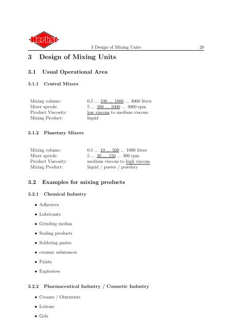
3 <strong>Design</strong> <strong>of</strong> <strong>Mixing</strong> <strong>Units</strong>3.1 Usual Operational Area3.1.1 Central <strong>Mixer</strong>s3 <strong>Design</strong> <strong>of</strong> <strong>Mixing</strong> <strong>Units</strong> 20<strong>Mixing</strong> volume:<strong>Mixer</strong> speeds:Product Viscosity:<strong>Mixing</strong> Product:0,5 ... 100 ... 1000 ... 3000 litres5 ... 200 ... 1000 ... 3000 rpmlow viscous to medium viscousliquid3.1.2 <strong>Planetary</strong> <strong>Mixer</strong>s<strong>Mixing</strong> volume:<strong>Mixer</strong> speeds:Product Viscosity:<strong>Mixing</strong> Product:0,5 ... 10 ... 500 ... 1000 litres5 ... 30 ... 150 ... 300 rpmmedium viscous to high viscousliquid / pastes / powdery3.2 Examples for mixing products3.2.1 Chemical Industry• Adhesives• Lubricants• Grinding medias• Sealing products• Soldering pastes• ceramic substances• Paints• Explosives3.2.2 Pharmaceutical Industry / Cosmetic Industry• Creams / Ointments• Lotions• Gels
3.3 Application <strong>of</strong> <strong>Mixing</strong> <strong>Units</strong> in Ex-Zones 21• Tooth Pastes• Eye Shadows• Perfumes• light curing finger nails3.2.3 Food Industry• Flavourings• Fruit Concentrates• Chocolate Products• Salad Dressings• Delicatessen salads• Cream Cheeses• Marinades• Spice Mixtures3.3 Application <strong>of</strong> <strong>Mixing</strong> <strong>Units</strong> in Ex-Zones3.3.1 IntroductionIn the past it was sufficient to design the electronic construction parts <strong>of</strong> a mixing unitaccording to their intended application in ex-zones. Since this transition period ended onJune 30th 2003 all mixing units have to be designed according to ATEX regulations [2].As a result (in the following) also all mechanical components <strong>of</strong> a mixing unit will have tocomply with the special requirements <strong>of</strong> an operation in Ex-zones. Further informationon explosion protection see [3, 4, 5, 6].3.3.2 Ex-Protection in <strong>Mixing</strong> <strong>Units</strong>Stirring and mixing units are classified as Other Operating Equipment(supplies) <strong>of</strong> GroupII. Table 3 shows a survey <strong>of</strong> the design significant datas.Classification <strong>of</strong> areas, the establishing <strong>of</strong> temperature classes and explosion groups is theresponsibility <strong>of</strong> the operator. The result <strong>of</strong> the danger assessment is to be recorded in theexplosion protection document and up-dated continually. This data allows the equipmentmanufacturer to design the mixing unit accordingly. The following is a prerequisite forthe design <strong>of</strong> agitation and mixing equipment for ex-zones.
3.5 Electrical Engineering 24Furthermore the electronic equipment can be laid out specially for operations in ex-zones(ATEX 94/9). It is common use to mount the main control box outside the ex-zone andto have an additional ex-pro<strong>of</strong> control box with the necessary operating elements on themixer. If wanted the main control box can also be built ex-pro<strong>of</strong>.3.5.2 Temperature measurementA frequent requirement in the mixing process is the recording <strong>of</strong> the product temperature.The reasons may be manifold; the product temperature should, for example, be keptconstant or should not exceed or lie below the minimum or maximum value. In the course<strong>of</strong> the mixing process the product temperature must go through a certain temperaturepr<strong>of</strong>ile. It is imperative that the correct product temperature be maintained in order toobtain a representative set value for the temperature control.The positioning <strong>of</strong> the temperature sensor plays an important role in measuring the producttemperature in the bowl. Generally the temperature elements are mounted stationary;they are mounted on a fixed location which can be through the bottom, the jacket orthe cover <strong>of</strong> the bowl in order to have contact with the product. Especially with mediumto high viscosity products this may present problems because no representative measurementscan be obtained <strong>of</strong> the height <strong>of</strong> the bowl due to the varying temperature. Alsothe flow pattern <strong>of</strong> the stirrer may have a considerable influence on the locally registeredtemperature. Furthermore, a temperature difference between the bowl jacket and themiddle <strong>of</strong> the bowl has to be registered. Operating several temperature sensors may curethis problem considerably.An optimal temperature value can be obtained by moving the sensor constantly throughthe product during the mixing process. This is the case for example with planetary mixers.The sensor and a transmitter are integrated in the stirring tool. The stirring tool movesthrough the product on a circular path as well as circulating around it’s own axis. Anadditional wall scraper transports the product constantly from the wall to the middle <strong>of</strong>the bowl. Herewith an optimal heat exchange is guaranteed and the sensor measures arepresentative product temperature. The sensor is placed above the product surface andseveral infrared diodes transmit the values to the receiver (without any contacts). Thetransmitter is operated by battery, which lasts approx. 3 years. The standard measuringrange lies at approx. -55 ◦ C and +125 ◦ C. Standard accuracy is 0,125 ◦ C. Figure 4shows the sensor with the transmitter.This measuring system has proved to be successful. Even product deposits on the sensorunit, i. e. creams, do not influence the transfer <strong>of</strong> temperature values. Even on existingmixing units this temperature measuring system can be installed later, it’s instrumentationand control techniques can be supplied and fitted individually to suit the specificmixing process.Alternatively a slip ring transmitter can be employed with higher temperatures.
3.5 Electrical Engineering 25Figure 4:Temperature Measuring System with Infrared Transmittancea) (on the left) installed in the <strong>Planetary</strong> <strong>Mixer</strong>b) (on the right) Sensor3.5.3 Program controlThere is a constantly growing demand for a constant quality <strong>of</strong> the mixing process. Thequality <strong>of</strong> the product should be guaranteed even with personnel changes or frequentchanges <strong>of</strong> products. Furthermore the end user <strong>of</strong>ten asks for a quality certificate, i. e. amixing protocol, from the producer. This should not present any problem thanks to controltechniques. Programming may correspond to the product which results in a smoothmixing process. Important parameters, such as temperature, pressure and revolutionscan be registered and considered by means <strong>of</strong> modern sensors. Single components <strong>of</strong> themixer, like drive, vacuum pump, heating or homogeniser may be controlled individually.This guarantees an optimal mixing process. The revolutions <strong>of</strong> the stirrer could be controlledeither depending on the present product viscosity or the shear sensitiveness. Fordegassing <strong>of</strong> the stirred product or sucking in additional mixing components the vacuumpump may be connected and the planetary mixer will open on it’s own towards the end<strong>of</strong> the mixing process. Even dosage, discharging and cleaning can be integrated into theprogramming, so that the personnel does not have to attend to the machine at all times.Thus several mixers may be operated, respectively different works be carried out, at thesame time, which results in saving time and costs. Important phases <strong>of</strong> the programmay be signalised optically or acoustically. Registrating measured values guarantees bestsafety techniques, i. e. switch <strong>of</strong>f the stirrer when the temperature limit is exceeded.
3.6 <strong>Design</strong> <strong>of</strong> the Machine 26No experience in programming is necessary in order to operate the control panel because itis controlled electronically. The actual process parameters (i. e. revolutions, temperatureand pressure) are shown constantly on the display. The mixer can be operated by programcontrol or manually.The programs may be adjusted at any time to varying demands, which is important forexample in the research and development area. For external data processing the actualparameters may be transferred to a PC via interphace; alternatively the planetary mixercould be fitted with it’s own printer or tape deck.The basic programming <strong>of</strong> the control system will be made customer orientated. Theprograms may be arranged for different products, saved, modified and recalled at anytime. Changes <strong>of</strong> programs may be carried out by the operator on the control panel. Thefollowing figure shows a possible version <strong>of</strong> the control unit.Figure 5:Unit for Program Control[Simatic OP7]3.6 <strong>Design</strong> <strong>of</strong> the Machine3.6.1 Choice <strong>of</strong> Fabrication MaterialAll parts in contact with the product are <strong>of</strong> stainless steel. The steel quality depends onthe medium to be mixed respectively on the customer requirements.In Table 4 you find frequently used stainless steel qualities.Other parts which are not in contact with the product are also (as far as possible) made<strong>of</strong> stainless steel.Special materials are possible upon request.
3.6 <strong>Design</strong> <strong>of</strong> the Machine 27Table 4:frequently used stainless steel qualitiesMaterial No. Shortname (EN 10088-2) ASTM / AISI BS1.4301 X 5 CrNi 18-10 304 304 S 151.4404 X 2 CrNiMo 17-12-2 316L 316 S 111.4541 X 6 CrNiTi 18-10 321 321 S 311.4571 X 6 CrNiMoTi 17-12-2 316TI 320 S 31AISI = American Iron and Steel Institute, ASTM = American Society for Testing and Materials,BS = British Standard3.6.2 Surface <strong>Design</strong>All parts in contact with the product are hand ground and polished. If necessary thesurface may also be electrical polished.For special applications a coating, i. e. with Teflon, is possible.3.6.3 Regulations and Guiding RulesAll <strong>Herbst</strong> mixers are projected and fabricated in line with the latest regulations andguiding rules. These are in accordance with the guide lines <strong>of</strong> the chemical industryand relate to GMP and FDA. Furthermore an authorization <strong>of</strong> the CE-stamping can beobtained.The Ex-zone is designed according to ATEX 94/9 and the mixing units have to undergoa single inspection by the technical surveyor (i. e. TÜV) if requested for zone 0 / 20.3.6.4 Safety Standards<strong>Herbst</strong> mixers are fitted with the necessary safety equipment, such as guards, bowl controlby proximity switch and manually operating controls <strong>of</strong> the bowl and the level adjustment<strong>of</strong> the mixer head.<strong>Mixing</strong> units located in ex-areas (zone 1/21) are fitted with additional safety measuressuch as internal bowl wall scraper elements made <strong>of</strong> conductive material and level control<strong>of</strong> double jacketed bowls.3.6.5 Suitable design to allow ease <strong>of</strong> cleaningAll parts in contact with the product are designed in such a way that easy cleaning ispossible. The surface shape is also subject to easy cleaning. Gaps are being avoided orarranged in such a way that they do not represent problems when cleaning.
3.6.6 Qualification and Validation3.6 <strong>Design</strong> <strong>of</strong> the Machine 28A qualification, i. e. a functional test <strong>of</strong> the unit, has to be arranged (as preparation)prior to the unit validation.The qualification consists <strong>of</strong> the following partial steps:• <strong>Design</strong> Qualification DQ• Installation Qualification IQ• Operational Qualification OQ• Performance Qualification PQThe unit operator provides the specification requirements for the new mixing unit in the<strong>Design</strong> Qualification (DQ). These requirements constitute the design and constructionbasis which are confirmed in the Installation Qualification (IQ). The specification designand installation as listed in the accompanying DQ & IQ Certificates are to be checked forcompletion and conformity.This check, if not otherwise specified, is carried out visually. The unit design drawings, theIQ check list, the control circuit diagram and the documentary files serve as examinationmaterial.To be checked:• Unit components• Feed and discharge connections• Materials and substances in contact with the product• Documents• DrawingsThe installation qualification (IQ) as well as the function qualification (OQ) can be carriedout by the manufacturer, whereby both steps occur in close contact with and in thepresence <strong>of</strong> the end user.The OQ test program is the documentary evidence that the unit operates, trouble freeand with repeatable results all in accordance with the customers approved design andspecification. For these mechanical functional tests drinking water is used as the testmedium.
3.6 <strong>Design</strong> <strong>of</strong> the Machine 29To be tested:• Safety equipment• Unit behaviour on power failure• Function <strong>of</strong> the main components• Function <strong>of</strong> display elements and sensors• Function <strong>of</strong> alarm equipmentAfter a successful operational qualification (OQ) further qualification / validation steps,such as Process Qualification (PQ) which provides documentary pro<strong>of</strong> that the unit fulfilsall specified requirements under process condition, may be required by the operator.Validation is the acceptance <strong>of</strong> an operating unit. Test runs have to prove that the appliedprocess and operation allow for a uniform and trouble free production.