turfcat 500 series - Golf Ventures
turfcat 500 series - Golf Ventures
turfcat 500 series - Golf Ventures

You also want an ePaper? Increase the reach of your titles
YUMPU automatically turns print PDFs into web optimized ePapers that Google loves.
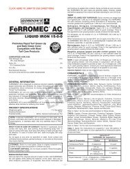
Parts &<br />
Maintenance<br />
Manual<br />
Jacobsen Turfcat®<br />
<strong>500</strong> Series<br />
Kubota D-905EB<br />
Diesel Engine<br />
T523D 2WD Product No. 66146<br />
Kubota D-1105E<br />
Diesel Engine<br />
T528D 2WD Product No. 66148<br />
T528D 4WD Product No. 66149<br />
Kubota D-1105T<br />
Diesel Engine<br />
T535D 4WD Product No. 66150<br />
Briggs & Stratton 580447<br />
Gasoline Engine<br />
T531G 2WD Product No. 66151<br />
BOB-CAT • BUNTON • CUSHMAN • JACOBSEN • RANSOMES • RYAN<br />
!<br />
WARNING: If incorrectly used this machine can cause severe injury. Those who use<br />
and maintain this machine should be trained in its proper use, warned of its dangers<br />
and should read the entire manual before attempting to set up, operate, adjust or service<br />
the machine.<br />
TURF CARE AND SPECIALTY PRODUCTS<br />
Litho in U.S.A. 3-2000 Part No. 2809902
To Order Parts<br />
1. Write your full name and complete address on the<br />
order.<br />
2. Explain where and how to make shipment.<br />
3. Give product number, name and serial number that is<br />
stamped on the name plate or serial plate of your product.<br />
4. Order by the quantity desired, the part number, paint<br />
code, and description of the part as given in the parts<br />
list.<br />
5. Send or bring the order to an authorized Textron Turf<br />
Care And Specialty Products Dealer.<br />
6. Inspect all shipments on receipt. If any parts are damaged<br />
or missing, file a claim with the carrier before<br />
accepting.<br />
7. Do not return material without a letter of explanation,<br />
listing the parts being returned. Transportation charges<br />
must be prepaid.<br />
Use of other than Textron Turf Care And Specialty Products authorized parts will void the warranty.<br />
Safety<br />
1.1 Operating Safety ........................................... 4<br />
1.2 Important Safety Notes ................................. 5<br />
Specifications<br />
2.1 Product Identification ..................................... 6<br />
2.2 Tractor ........................................................... 6<br />
2.3 Engine ........................................................... 7<br />
2.4 Accessories ................................................... 7<br />
2.5 Support Literature ......................................... 7<br />
Adjustments<br />
3.1 General ......................................................... 8<br />
3.2 Cutting Height ............................................... 8<br />
3.3 Neutral Adjustment ........................................ 9<br />
3.4 Speed ............................................................ 9<br />
3.5 Parking Brake / Turn Assist Pedals ............. 10<br />
3.6 Traction Pedal Speed Limiter ...................... 10<br />
3.7 Engine Belt .................................................. 11<br />
3.8 Throttle and Choke ...................................... 11<br />
Table of Contents<br />
Maintenance<br />
4.1 General ........................................................12<br />
4.1 Engine ..........................................................12<br />
4.2 Engine Oil ....................................................12<br />
4.3 Air Filter .......................................................13<br />
4.4 Fuel ..............................................................13<br />
4.5 Fuel System .................................................14<br />
4.6 Battery .........................................................14<br />
4.7 Jump Starting ...............................................14<br />
4.8 Charging Battery ..........................................15<br />
4.9 Hydraulic Hoses ...........................................15<br />
4.10 Hydraulic Oil ................................................16<br />
4.11 Electrical System .........................................16<br />
4.12 Muffler and Exhaust .....................................17<br />
4.13 Radiator .......................................................17<br />
4.14 Rollover Protection Structure (ROPS) .........17<br />
4.15 Tires .............................................................18<br />
4.16 Wheel Mounting Procedure .........................18<br />
4.17 Care and Cleaning .......................................18<br />
4.18 Storage ........................................................19<br />
Maintenance & Lubrication charts<br />
5.1 General ........................................................20<br />
5.2 Maintenance Chart ...................................... 20<br />
5.3 Lubrication Chart .........................................21<br />
Troubleshooting<br />
6.1 General Troubleshooting .............................22<br />
Parts Catalog<br />
7.1 Table of Contents ........................................23<br />
This manual is designed for the Maintenance and Adjustment of this equipment.<br />
Use the maintenance and adjustment instructions included in this manual and the operating<br />
instructions included in the Safety and Operation Manual to service the machine.<br />
The Safety and Operation Manual must be kept in the pouch on the back of the seat at all times<br />
for reference by the operator.<br />
Copyright 1999 Textron Inc.<br />
“All rights reserved, including the right to reproduce this material or portions thereof in any form.”<br />
All information in this publication is based on information available at time of approval for printing. Textron Turf Care<br />
and Specialty Products reserves the right to make changes at any time without notice and without incurring any<br />
obligation.
Suggested Stocking Guide<br />
To Keep your Equipment fully operational and productive, maintain a stock of the more commonly used maintenance<br />
items. We have included part numbers for additional support materials and training aids. A more complete listing of<br />
accessories and attachments can be found in the Specifications Section<br />
Service Parts<br />
Qty. Part No. Description Qty. Part No. Description<br />
557759 Diesel Engine Oil Filter <strong>500</strong>3069 Gas Engine Oil Filter<br />
550489 Diesel Engine Fuel Filter Element <strong>500</strong>3070 Gas Engine Fuel Filter Element<br />
<strong>500</strong>3055 Diesel Ignition Key 558015 Gas Ignition Key<br />
<strong>500</strong>0919 Diesel Air Cleaner Element <strong>500</strong>0913 Gas Air Filter Element<br />
<strong>500</strong>2892 Hydraulic Filter Element<br />
Service Support Material<br />
Qty. Part No.<br />
Description<br />
2809903 Safety & Operation Manual<br />
2809902 Parts & Maintenance Manual<br />
3005710 Engine Parts Catalog<br />
Qty.<br />
Description<br />
Service Manual<br />
How To Use This Manual<br />
Abbreviations<br />
N/S - Not serviced seperately, can only be obtained by ordering main component or kit.<br />
AR -Variable quantity or measurement is required to obtain correct adjustment.<br />
Symbols such as ▲, next to the item number, indicate that a note exists which contain additional information<br />
important in ordering that part.<br />
Indented Items<br />
Bulleted items indicate component parts that are included as part of an assembly or another component. These parts<br />
can be ordered separetely or as part of the main component.<br />
Item Part No. Qty Description Serial Numbers/Notes<br />
▲ 1 123456 1 Mount, Valve Indicates a piece part<br />
2 789012 1 Valve, Lift Includes Items 2 and 3<br />
3 345678 1 • Handle Serviced part included with Item 2<br />
4 N/S 1 • Seal Kit Non serviced part included with Item 2<br />
5 901234.6 1 Screw, 1/4-20 x 2” Hex Head Indicates a part painted Jacobsen Orange<br />
3
1 SAFETY<br />
1 SAFETY<br />
1.1 OPERATING SAFETY ______________________________________________________<br />
! WARNING !<br />
EQUIPMENT OPERATED IMPROPERLY OR BY UNTRAINED PERSONNEL CAN BE DANGEROUS.<br />
Familiarize yourself with the location and proper use of all controls. Inexperienced operator’s should receive instruction<br />
from someone familiar with the equipment before being allowed to operate the machine.<br />
1. Safety is dependent upon the awareness, concern and<br />
prudence of those who operate or service the equipment.<br />
Never allow minors to operate any equipment.<br />
2. It is your responsibility to read this manual and all<br />
publications associated with this equipment (Safety<br />
and operation manual, engine manual, accessories<br />
and attachments). If the operator can not read English<br />
it is the owner’s responsibility to explain the material<br />
contained in this manual to them.<br />
3. Learn the proper use of the machine, the location and<br />
purpose of all the controls and gauges before you<br />
operate the equipment. Working with unfamiliar<br />
equipment can lead to accidents.<br />
4. Never allow anyone to operate or service the machine<br />
or its attachments without proper training and<br />
instructions; or while under the influence of alcohol or<br />
drugs.<br />
5. Wear all the necessary protective clothing and<br />
personal safety devices to protect your head, eyes,<br />
ears hands and feet. Operate the machine only in<br />
daylight or in good artificial light.<br />
6. Inspect the area where the equipment will be used.<br />
Pick up all the debris you can find before operating.<br />
Beware of overhead obstructions (low tree limbs,<br />
electrical wires, etc.) and also underground obstacles<br />
(sprinklers, pipes, tree roots, etc.) Enter a new area<br />
cautiously. Stay alert for hidden hazards.<br />
7. Never direct discharge of material toward bystanders,<br />
nor allow anyone near the machine while in operation.<br />
The owner/operator can prevent and is responsible for<br />
injuries inflicted to themselves, to bystanders and<br />
damage to property.<br />
8. Never operate equipment that is not in perfect working<br />
order or is without decals, guards, shields, discharge<br />
deflectors or other protective devices securely fastened<br />
in place.<br />
9. Never disconnect or bypass any switch.<br />
10. Carbon monoxide in the exhaust fumes can be fatal<br />
when inhaled. Never operate the engine without proper<br />
ventilation.<br />
11. Fuel is highly flammable, handle with care.<br />
12. Keep the engine clean. Allow the engine to cool before<br />
storing and always remove the ignition key.<br />
13. Disengage all drives and engage parking brake before<br />
starting the engine (motor). Start the engine only when<br />
sitting in operator’s seat, never while standing beside<br />
the unit.<br />
14. Equipment must comply with the latest federal, state,<br />
and local requirements when driven or transported on<br />
public roads.<br />
15. Never use your hands to search for oil leaks. Hydraulic<br />
fluid under pressure can penetrate the skin and cause<br />
serious injury.<br />
16. Operate the machine up and down the face of the<br />
slopes (vertically), not across the face (horizontally).<br />
17. To prevent tipping or loss of control, do not start or<br />
stop suddenly; reduce speed when making sharp<br />
turns. Use caution when changing direction on slopes.<br />
18. Always use the seat belt when operating tractors<br />
equipped with a ROPS.<br />
Never use a seat belt when operating tractors<br />
without a ROPS.<br />
19. Keep legs, arms and body inside the seating<br />
compartment while the vehicle is in motion.<br />
This machine is to be operated and maintained as specified in this manual and is intended for the professional<br />
maintenance of specialized turf grasses. It is not intended for use on rough terrain or long grasses.<br />
4
SAFETY 1<br />
1.2 IMPORTANT SAFETY NOTES ________________________________________________<br />
!<br />
This safety alert symbol is used to alert you to potential hazards.<br />
DANGER - Indicates an imminently hazardous situation which, if not avoided, WILL result in death or serious injury.<br />
WARNING - Indicates a potentially hazardous situation which, if not avoided, COULD result in death or serious injury.<br />
CAUTION - Indicates a potentially hazardous situation which, if not avoided, MAY result in minor or moderate injury and<br />
property damage. It may also be used to alert against unsafe practices.<br />
For pictoral clarity, some illustrations in this manual may show shields, guards or plates open or removed. Under no<br />
circumstances should this equipment be operated without these devices securely fastened in place<br />
! WARNING !<br />
The operator back-up system on this tractor prevents the tractor from starting<br />
unless the brake pedal is engaged, mower switch is off and traction pedal is in<br />
neutral. The system will stop the engine if the operator leaves the seat without<br />
engaging the parking brake and setting the mower switch off.<br />
NEVER operate tractor unless the operator back-up system is working.<br />
! WARNING !<br />
1. Before leaving the operator’s position for any reason:<br />
a. Return traction pedal to neutral.<br />
b. Disengage all drives.<br />
c. Lower all implements to the ground.<br />
d. Engage parking brake.<br />
e. Stop engine and remove the ignition key.<br />
2. Keep hands, feet, and clothing away from moving parts. Wait for all<br />
movement to stop before you clean, adjust or service the machine.<br />
3. Keep the area of operation clear of all bystanders and pets.<br />
4. Never carry passengers, unless a seat is provided for them.<br />
5. Never operate mowing equipment without the discharge deflector securely<br />
fastened in place.<br />
By following all instructions in this manual, you will prolong the life of your machine and maintain its maximum efficiency.<br />
Adjustments and maintenance should always be performed by a qualified technician.<br />
If additional information or service is needed, contact your Authorized Textron Turf Care and Specialty Products Dealer who is<br />
kept informed of the latest methods to service this equipment and can provide prompt and efficient service. Use of other<br />
than original or authorized Textron Turf Care and Spedialty Products parts and Accessories will void the warranty.<br />
5
2 SPECIFICATIONS<br />
2 SPECIFICATIONS<br />
2.1 PRODUCT IDENTIFICATION_________________________________________________<br />
66146.............................. T523D, 2 Wheel Drive<br />
66148.............................. T528D, 2 Wheel Drive<br />
66149.............................. T528D, 4 Wheel Drive<br />
66150.............................. T535D, 4 Wheel Drive<br />
66151.............................. T531G, 2 Wheel Drive<br />
Serial Number ................ An identification plate, like the one<br />
shown, listing the serial number, is<br />
attached to the frame of the<br />
tractor and is located on the<br />
operator’s right just over the rear<br />
axle.<br />
Always provide the serial number of the unit when ordering<br />
replacement parts or requesting service information.<br />
Product<br />
EEC Sound<br />
Power<br />
Sound Pressure<br />
Level Operator Ear<br />
Vibration M/S 2<br />
Arms<br />
Body<br />
66146 < 90 dba < 105 dba 3.38 0.084<br />
66148 < 90 dba < 105 dba 3.38 0.084<br />
66149 < 90 dba < 105 dba 3.38 0.084<br />
66150 < 90 dba < 105 dba 3.38 0.084<br />
66151 < 90 dba < 105 dba 3.38 0.084<br />
TEXTRON TURF CARE AND SPECIALTY PRODUCTS<br />
RACINE, WI<br />
66146 1601<br />
MADE IN U.S.A.<br />
2.2 TRACTOR ________________________________________________________________<br />
Tires:<br />
Front ........................ 23 x 10.5 - 12, 2 ply<br />
Rear ......................... 16 x 7.5 - 8, 4 ply<br />
Pressure ................... 10-12 psi (69 - 83 kPa)<br />
Recommended Battery. SIze<br />
Standard ................... 12V, AABM Group 22NF<br />
250 Cold Cranking amps<br />
Cold Weather............ 12V, AABM Group 45 GMP<br />
400 Cold cranking amps<br />
Service Brake ................ Dynamic braking through traction<br />
circuit<br />
Parking Brake................ 7 x 1.75in. (178 x 44 mm)<br />
drum type<br />
Speed:<br />
Forward (2 WD) ........ 0 - 10.6 mph (17.1kph)<br />
Forward (4 WD) ........ 0 - 6.6 mph (10.6 kph)<br />
Reverse ................... 0 - 5.2 mph (8.4 kph)<br />
Turning Radius ............. 20 in. (51.2 cm) left<br />
22.5 in. (57.6 cm) right<br />
Production:<br />
60 in. ........................ 2.8 acres/hr @ 6 mph<br />
72 in. ......................... 3.5 acres/hr @ 6 mph<br />
Decks<br />
Side discharge .......... 60 in. (152 cm)<br />
72 in. (183 cm)<br />
Rear Discharge......... 60 in. (152 cm)<br />
72 in. (183 cm)<br />
Mulcherizer .............. 60 in. (152 cm)<br />
72 in. (183 cm)<br />
6<br />
Flail .......................... 60 in. (152 cm)<br />
Tire Pressure ............ 22-24 psi (152-165 kPa)<br />
Hydraulic System:<br />
Capacity.......................... 8 U.S. gal. (30.3 liter)<br />
Fluid Type....................... ISO VG68<br />
Cooling ........................... Oil Cooler<br />
Return Line Filter............ 10 micron<br />
Traction........................... Hydrostatic transmission<br />
Steering ......................... Hydraulic power steering<br />
Dimensions (Tractor only):<br />
Length............................. 89.3 (229 cm)<br />
Height ............................ 42.5 (109 cm) to top of hood<br />
Width .............................. 53.0 (136 cm)<br />
Wheel Base .................... 59.5 (152 cm)<br />
Ground Clearance .......... 7.6 (19.5 cm)<br />
Weights:<br />
Tractor only..................... 1300 lbs. (590 kg)<br />
Tractor with decks:<br />
60 in. Side discharge ...... 1600 lbs. (726 kg)<br />
60 in. Rear discharge ..... 1635 lbs. (742 kg)<br />
72 in Side Discharge ...... 1685 lbs. (766 kg)<br />
72 in. Rear Discharge..... 1660 lbs. (755 kg)<br />
60 in. Mulcherizer .......... 1575 lbs. (716 kg)<br />
72 in. Mulcherizer ........... 1660 lbs. (755 kg)<br />
60 in. Flail ....................... 1666 lbs. (757 kg)
SPECIFICATIONS 2<br />
2.3 ENGINE __________________________________________________________________<br />
T523D T528D T535D T531G<br />
Make Kubota Kubota Kubota Briggs & Stratton<br />
Model D905 E D1105 E D1105 TB 580447 0115 E2<br />
Type - 4 cycle, liquid cooled Diesel Diesel Diesel Gas<br />
Horsepower @ 3000 rpm - Hp (kW) 22.5 (16.8) 28 (20.9) 33 (24.6) 31 (23)<br />
DIsplacement - in 3 (cm 3 ) 54.9 (899) 68.5 (1123) 68.5 (1123) 58.1 (952)<br />
Torque @ 2200 rpm - ft.lbs. (Nm) 39.7 (53.8) 54 (73) 60 (81) 50.5 (68.4)<br />
Fuel<br />
Type<br />
Minimum Rating<br />
Capacity - U.S. gal. (liters)<br />
No. 2 Diesel<br />
Cetane rating - 45<br />
12 (45.4)<br />
Unleaded Gasoline<br />
Octane - 85<br />
12 (45.4)<br />
High speed - rpm 3150 no load 3150 no load<br />
Low Idle - rpm 1750 no load 1200 no load<br />
Lubrication<br />
Type<br />
Capacity<br />
Classification<br />
Air Filter<br />
SAE10 W30<br />
5.4 qt. (5.1 liters)<br />
CD, CE<br />
Dry type with service indicator<br />
Alternator - Amp 40<br />
SAE 10W30<br />
3.5 qt. (3.3 liter)<br />
SE or higher<br />
2.4 ACCESSORIES____________________________________________________________<br />
Refer to your area Textron Turf Care And Specialty Products Dealer to order the following accessories and attachments.<br />
Caster Wheel Kit ............. solid - for 60 in (152 cm) deck<br />
Caster Wheel Kit .... pneumatic - for 60 in (152 cm) deck<br />
Caster Wheel Kit ............. solid - for 72 in (183 cm) deck<br />
Caster Wheel Kit ...... pneumatic - for 72 in183 cm) deck<br />
Canopy/Sunshade .......................requires 2 post ROPS<br />
ROPS, 2 post .............................................with seat belt<br />
Differential Lock Kit .........................................................<br />
Four Wheel Drive Kit.......................................................<br />
Light Kit ...........................................................................<br />
Standard Seat Suspension .............................................<br />
Deluxe Seat Suspension.................................................<br />
Arm Rests...................................................................(2)<br />
Quick Disconnect.......... Full kit - tractor and attachment<br />
Quick Disconnect ............Half kit - tractor or attachment<br />
Rear Wheel Weights.......................................................<br />
Front Wheel Weights ......................................................<br />
Air Blow Gun...................................................................<br />
Orange Touch-up Paint .............................. 12 oz. spray<br />
Tire Chains .....................................................................<br />
2.5 SUPPORT LITERATURE ____________________________________________________<br />
Contact your Textron Turf Care And Specialty Products Dealer for a complete listing of literature.<br />
Safety and Operation Manual<br />
Parts and Maintenance Manual<br />
Rotary Mower Parts and Maintenance Manual<br />
Operator Training Video<br />
Service & Repair Manual<br />
Engine Manuals - consult engine manufacturer<br />
7
3 ADJUSTMENTS<br />
3 ADJUSTMENTS<br />
3.1 GENERAL________________________________________________________________<br />
! WARNING !<br />
To prevent injury, lower implements to the ground,<br />
disengage all drives, engage parking brake, stop<br />
engine and remove key from ignition switch before<br />
making any adjustments or performing maintenance.<br />
Make sure the tractor is parked on a solid and level<br />
surface. Never work on a tractor that is supported only<br />
by the jack. Always use jack stands.<br />
If only the front or rear of the tractor is raised, place<br />
chocks in front of and behind the wheels that are not<br />
raised.<br />
1. Adjustments and maintenance should always be performed<br />
by a qualified technician. If proper adjustment<br />
cannot be made, contact an authorized Textron Turf<br />
Care And Specialty Products Dealer.<br />
2. Replace, do not adjust, worn or damaged<br />
components.<br />
3. Do not wear jewelry or loose fitting clothing when<br />
making adjustments or repairs.<br />
CAUTION: Be careful to prevent entrapment<br />
of the hands and fingers between mov-<br />
!<br />
ing and fixed components of the machine<br />
4. Do not change governor settings or overspeed the<br />
engine.<br />
5. For adjustments and maintenance of the cutting<br />
unit, refer to the Rotary Mower Maintenance<br />
Manual.<br />
3.2 INSTALLING DECK ________________________________________________________<br />
Assemble decks following instructions included in<br />
accessory manual. For installation on tractor follow<br />
instructions below.<br />
1. Remove push arms (B) from deck and install them<br />
on tractor as shown.<br />
2. Position deck in front of tractor and attach arms to<br />
deck. Install pivot pins (D) in arm so cotter pins face<br />
the inside of the deck as shown.<br />
3. Attach chain (E) to deck and lift arm on tractor as<br />
shown. Use correct hole for deck size.<br />
Hole<br />
Deck Size<br />
2 72” (185 cm)<br />
1 60” (154 cm)<br />
1<br />
2<br />
E<br />
B<br />
D<br />
4. Lubricate spline (C) in deck using NLGI Grade 2<br />
grease. Install motor as shown and secure using<br />
capscrew and lockwasher supplied with deck.<br />
5. Set cutting height.<br />
Other Attachments<br />
For assembly and installation of flail and other<br />
attachments refer to manual supplied with them.<br />
C<br />
D<br />
TC017<br />
Figure 3A<br />
8
ADJUSTMENTS 3<br />
3.3 NEUTRAL ADJUSTMENT ___________________________________________________<br />
The traction pedal is designed to return to neutral<br />
whenever the forward or reverse foot pedals are<br />
released. If the tractor continues to creep after the<br />
traction pedal is released, check neutral adjustment and<br />
adjust traction pedal linkage.<br />
1. Disconnect pump linkage from traction pedal.<br />
2. With linkage disconnected, check position of return<br />
arm on drive pump. Pointer (E) on arm should be<br />
centered in the sensing area of the switch (G).<br />
Note: This switch forms part of the operator back-up<br />
system and senses when the traction pedal is in<br />
neutral. If the operator back-up system fails to<br />
operate properly have the switch checked and<br />
replaced before operating tractor.<br />
3. To adjust pointer, loosen the two screws (F) holding<br />
return arm bracket to pump. Position bracket until<br />
pointer is centered. Tighten bracket in place.<br />
4. Check operator back-up system and operation of<br />
traction pedal after adjustment has been made.<br />
Four Wheel Drive<br />
Machines equipped with four wheel drive include a switch<br />
to prevent operation of four drive in reverse. This switch<br />
is located on the same bracket as the neutral switch.<br />
When replacing switch the sensing area (H) must be<br />
positioned under return arm as shown with pump in<br />
neutral.<br />
G<br />
H<br />
E<br />
F<br />
TC019<br />
Figure 3B<br />
3.4 SPEED___________________________________________________________________<br />
Before making any speed adjustment at pump, check<br />
that the engine is operating at full rpm, under load, and<br />
throttle lever is set correctly. If adjustment is required, it is<br />
only necessary to adjust forward speed.<br />
7. Check operator back-up system and operation of<br />
traction pedal after adjustment has been made.<br />
To limit forward speed while mowing adjust traction pedal<br />
speed limiter, Section 3.6.<br />
1. Check neutral adjustment and adjust if required.<br />
2. Disconnect rod end (I) from traction pedal.<br />
3. Push traction pedal forward (J) until it touches floor<br />
panel.<br />
4. Push return arm (K) on drive pump back until it hits<br />
internal stop on pump housing. In this position the<br />
pump is at full stroke.<br />
5. With both the pump and traction pedal at full<br />
forward stroke, adjust rod end (I) at pedal in or out<br />
so it aligns directly with hole (L) in link arm.<br />
Note: Additional adjustment can be made on rod end<br />
at pump if necessary.<br />
J<br />
K<br />
L<br />
I<br />
TC022<br />
Figure 3C<br />
6. Connect rod end to pedal and tighten jam nut on rod<br />
to secure adjustment.<br />
9
3 ADJUSTMENTS<br />
3.5 PARKING BRAKE / TURN ASSIST PEDALS ____________________________________<br />
The turn assist pedals provide independent braking of<br />
the left and right front wheels to allow for tight turns.<br />
When operated together with the brake lock they act as a<br />
parking brake.<br />
These brakes are self-adjusting and should not require<br />
additional adjustment under normal operating conditions.<br />
However, if pedal travel becomes excessive, or brakes<br />
have been replaced or serviced, minor adjustments may<br />
be required.<br />
If linings or brake drums appear worn or damaged, have<br />
them replaced immediately by an experienced service<br />
technician.<br />
Left and right brake cables are adjusted independently of<br />
each other.<br />
To adjust brakes:<br />
1. Check brake return spring adjustment (P). With<br />
brake pedal released spring should measure 1-1/8<br />
inch (29 mm).<br />
2. Check that brake free travel measures 1 in. (25<br />
mm). Use nuts (O) to adjust free travel as required.<br />
3. Repeat procedure for other brake.<br />
Start tractor and check operation of turn assist pedals.<br />
To check parking brake park tractor on an incline (approx.<br />
16.7° slope) and engage and lock parking brake. Brake<br />
must prevent tractor from rolling.<br />
Brake Switch<br />
The brake switch (M) forms part of the operator back-up<br />
system and senses when the parking brake is engaged.<br />
This switch cannot be adjusted. If the operator back-up<br />
system fails to operate properly have the switch checked<br />
and replaced before operating tractor.<br />
M<br />
O<br />
P<br />
TC013<br />
Figure 3D<br />
3.6 TRACTION PEDAL SPEED LIMITER __________________________________________<br />
Cutting quality is better at speeds well below the<br />
transport speed of the tractor. An initial mow speed of five<br />
to six mph is set at the factory and should be satisfactory<br />
for most cutting conditions. Local turf conditions however<br />
may respond better to a different speed.<br />
To set mow speed, loosen jam nut (Q) and adjust stop<br />
screw up to reduce speed, down to increase speed.<br />
Tighten nut to hold adjustment in place.<br />
Q<br />
TC003<br />
Figure 3E<br />
10
ADJUSTMENTS 3<br />
3.7 ENGINE BELT ____________________________________________________________<br />
Inspect and adjust new belt after first 50 hours of<br />
operation. Check and adjust annually thereafter.<br />
Adjust alternator pulley so belt deflects 1/4” to 5/16” (6 -8<br />
mm) with a 20 lb. push at midpoint between pulleys. See<br />
engine manual.<br />
A<br />
To adjust, loosen alternator mounting bolts (A) and adjust<br />
alternator until proper belt tension is achieved, then<br />
retighten bolts.<br />
TC023<br />
Figure 3F<br />
3.8 THROTTLE AND CHOKE ____________________________________________________<br />
Check throttle adjustment, if engine runs below<br />
recommended rpm with throttle lever in its high speed<br />
position. On tractors equipped with gas engines adjust<br />
choke control, if engine is hard to start.<br />
For other engine adjustments refer to the Engine<br />
Owner’s Manual supplied by the engine<br />
manufacturer.<br />
Gas engines<br />
1. Position throttle lever in its high speed position so<br />
that 1/16 - 1/4 in. (2-6 mm) gap exists between lever<br />
and panel. See E- Figure 3H.<br />
2. Pull up choke control on instrument panel to its<br />
choke position.<br />
3. Loosen cable casing clamp screw (A) on engine.<br />
4. Move throttle casing and wire (B) until throttle lever<br />
on engine touches high speed screw (C). Move<br />
choke cable and casing (D) until choke valve is<br />
completely closed<br />
5. Tighten casing clamp (A).<br />
A<br />
B<br />
Gas engine<br />
D<br />
C<br />
TC009<br />
Figure 3G<br />
Diesel Engines<br />
1. Remove side cover from instrument panel.<br />
2. Position throttle lever in its high speed position so<br />
that 1/16 - 1/4 in. (2-6 mm) gap exists between lever<br />
and panel (E).<br />
3. With throttle lever on engine against max. speed<br />
stop, adjust throttle cable nuts (A) so that eyelet (B)<br />
on cable fits over on pin as shown.<br />
4. Install push nut so that eyelet slides freely when<br />
lever is rotated.<br />
B<br />
A<br />
E<br />
TC008<br />
Figure 3H<br />
11
4 MAINTENANCE<br />
4 MAINTENANCE<br />
4.1 GENERAL________________________________________________________________<br />
! WARNING !<br />
Before you clean, adjust, or repair this equipment,<br />
disengage all drives, lower implements to the ground,<br />
engage parking brake, stop engine and remove key<br />
from ignition switch to prevent injuries<br />
Make sure the tractor is parked on a solid and level<br />
surface. Never work on a tractor that is supported only<br />
by the jack. Always use jack stands.<br />
1. Adjustment and maintenance should always be performed<br />
by a qualified technician. If proper adjustments<br />
cannot be made, contact an Authorized<br />
Textron Turf Care And Specialty Products Dealer.<br />
2. Inspect the equipment on a regular basis, establish<br />
a maintenance schedule and keep detailed records.<br />
a. Keep the equipment clean.<br />
b. Keep all moving parts properly adjusted and<br />
lubricated.<br />
c. Replace worn or damaged parts before operating<br />
the machine.<br />
d. Keep all fluids at their proper levels.<br />
e. Keep shields in place and all hardware securely<br />
fastened.<br />
f. Keep tires properly inflated.<br />
3. Do not wear jewelry or loose fitting clothing when<br />
making adjustments or repairs.<br />
4. Use the illustrations in the Parts Catalog as<br />
reference for the disassembly and reassembly of<br />
components.<br />
5. Recycle or dispose of all hazardous materials<br />
(batteries, fuel, lubricants, anti-freeze, etc.)<br />
according to local, state or federal regulations.<br />
6. For adjustments and maintenance of the cutting<br />
unit, refer to the Rotary Mower Maintenance<br />
Manual.<br />
4.1 ENGINE _________________________________________________________________<br />
IMPORTANT: A separate Engine Manual, prepared by<br />
the engine manufacturer, is supplied with this tractor.<br />
Read the engine manual carefully until you are<br />
familiar with the operation and maintenance of the<br />
engine. Proper attention to the engine<br />
manufacturer’s directions will assure maximum<br />
service life of the engine. To order replacement<br />
engine manuals contact the engine manufacturer.<br />
The proper break-in of a new engine can make a<br />
considerable difference to the performance and life of the<br />
engine.<br />
During the break-in period, Textron Turf Care And<br />
Specialty Products recommends the following:<br />
1. During the first 50 hours of operation, a new engine<br />
should be allowed to reach an operating temperature<br />
of at least 140°F (60°C) prior to operation at full load.<br />
2. Check the engine oil level twice daily during the first<br />
50 hours of operation. Higher than normal oil<br />
consumption is not uncommon during the initial<br />
break-in period.<br />
3. Change engine oil and oil filter element after first 50<br />
hours of operation.<br />
4. Check and adjust fan and alternator belt.<br />
5. Refer to Section 5.2 and Engine Manual for specific<br />
maintenance intervals.<br />
If the injection pump, injectors or the fuel system require<br />
service, contact an authorized Textron Turf Care And<br />
Specialty Products Dealer.<br />
Note: The tractor is designed to operate and cut most<br />
efficiently at the preset governor setting. Do not change<br />
the engine governor settings or overspeed the engine.<br />
4.2 ENGINE OIL ______________________________________________________________<br />
Check the engine oil at the start of each day, before<br />
starting the engine. If the oil level is low, remove oil filler<br />
cap and add oil as required. Do not overfill.<br />
Perform initial oil change after first 50 hours of operation.<br />
Change every 200 hours thereafter.<br />
12<br />
Refer to engine specifications, Section 2.3 and engine<br />
manufacturer’s Owner’s manual for oil requirements.
MAINTENANCE 4<br />
4.3 AIR FILTER _______________________________________________________________<br />
Check the service indicator daily. Replace air cleaner<br />
element immediately when red band become visible (A).<br />
Do not remove the element for inspection or<br />
cleaning. Unnecessary removal of the filter increases<br />
the risk of injecting dust and other impurities into the<br />
engine.<br />
When service is required, first clean the outside of the<br />
filter housing; then remove the old element as gently as<br />
possible and discard.<br />
4. Reassemble cap making sure it seals completely<br />
around the filter housing. Dust evacuator (C) must<br />
be facing down.<br />
5. Check all hoses and air ducts. Tighten hose clamps.<br />
A<br />
B<br />
1. Carefully clean the inside of the filter housing without<br />
allowing dust into the air intake.<br />
2. Inspect the new element. Do not use a damaged<br />
element and never use an incorrect element.<br />
3. Assemble the new element and make sure it seats<br />
properly. Reset the indicator by depressing button<br />
(B).<br />
C<br />
TC006<br />
Figure 4A<br />
4.4 FUEL ____________________________________________________________________<br />
Handle fuel with care - it is highly flammable. Use an<br />
approved container, the spout must fit inside the fuel filler<br />
neck. Avoid using cans and funnels to transfer fuel.<br />
! WARNING !<br />
Never remove the fuel cap from the fuel tank, or add<br />
fuel, when the engine is running or while the engine is<br />
hot.<br />
• Store fuel according to local, state or federal<br />
ordinances and recommendations from your fuel<br />
supplier.<br />
• Never overfill or allow the tank to become empty.<br />
Read Engine Owner’s Manual for additional fueling<br />
information.<br />
Do not smoke when handling fuel. Never fill or drain<br />
the fuel tank indoors.<br />
Do not spill fuel and clean spilled fuel immediately.<br />
Never handle or store fuel containers near an open<br />
flame or any device that may create sparks and ignite<br />
the fuel or fuel vapors.<br />
Be sure to reinstall and tighten fuel cap securely.<br />
• Fill fuel tank to full mark on fuel gauge.<br />
• For diesel engines use clean, fresh, #2 Diesel fuel.<br />
minimum cetane rating 45. For gasoline engines use,<br />
clean, fresh, regular grade unleaded gasoline,<br />
minimum octane 85.<br />
13
4 MAINTENANCE<br />
4.5 FUEL SYSTEM ____________________________________________________________<br />
Refer to Section 5.2 for specific maintenance intervals.<br />
Visually check fuel lines and clamps daily, before<br />
operating tractor. Replace fuel lines and clamps at the<br />
first sign of damage.<br />
Before replacing any filter, thoroughly clean the filter<br />
housing and the area around the filter. Dirt must not be<br />
allowed to enter into fuel system.<br />
Bleed the fuel system after the fuel filter and lines have<br />
been removed, or the fuel tank has become empty. See<br />
Engine Manual.<br />
To change fuel filter:<br />
1. Close fuel valve on tank; then remove and discard<br />
the existing filter.<br />
2. For spin on type filters, apply a light coat of oil to the<br />
gasket and hand tighten new filter.<br />
3. Fill fuel tank. On tractors equipped with diesel<br />
engines open fuel valve and bleed the filter. See<br />
Engine Manual.<br />
4.6 BATTERY ________________________________________________________________<br />
Make absolutely certain the ignition switch is “Off” and<br />
the key has been removed before servicing the battery.<br />
!<br />
CAUTION: Always use insulated tools, wear<br />
protective glasses or goggles and protective<br />
clothing when working with batteries. You must<br />
read and obey all battery manufacturer’s instructions.<br />
Tighten cables securely to battery terminals and apply a<br />
light coat of silicone dielectric grease to terminals and<br />
cable ends to prevent corrosion. Keep vent caps and<br />
terminal covers in place<br />
Verify battery polarity before connecting or disconnecting<br />
the battery cables.<br />
1. When installing the battery, always assemble the<br />
RED, positive (+) battery cable first and the ground,<br />
BLACK, negative (-) cable last.<br />
2. When removing the battery, always remove the<br />
ground, BLACK, negative (-) cable first and the<br />
RED, positive (+) cable last.<br />
3. Make sure battery is properly installed and secured<br />
to the battery tray.<br />
Check the electrolyte level every 100 hours. Keep the<br />
cable ends, battery and battery posts clean.<br />
4.7 JUMP STARTING __________________________________________________________<br />
Before attempting to “jump start” the tractor, check the<br />
condition of the discharged battery. Section 4.6<br />
! WARNING !<br />
Batteries generate explosive hydrogen gas. To reduce<br />
the chance of an explosion, avoid creating sparks<br />
near battery. Always connect the negative jumper<br />
cable to the frame of the tractor with the discharged<br />
battery, away from the battery.<br />
When connecting jumper cables:<br />
1. Stop the engine on vehicle with good battery.<br />
2. Connect RED jumper cable to the positive (+)<br />
terminal on the good battery and to the positive (+)<br />
terminal on the “discharged” battery.<br />
3. Connect the BLACK jumper cable from the negative<br />
(-) terminal on the good battery to the frame of<br />
tractor with discharged battery.<br />
After cables have been connected, start the engine on<br />
the vehicle with the good battery then start the tractor.<br />
14
MAINTENANCE 4<br />
4.8 CHARGING BATTERY _____________________________________________________<br />
! WARNING !<br />
Charge battery in a well ventilated area. Batteries<br />
generate explosive gases. To prevent an explosion,<br />
keep any device that may create sparks or flames<br />
away from the battery.<br />
To prevent injury, stand away from battery when the<br />
charger is turned on. A damaged battery could<br />
explode.<br />
2. Whenever possible, remove the battery from the<br />
tractor before charging. If battery is not sealed,<br />
check that the electrolyte covers the plates in all the<br />
cells.<br />
3. Make sure the charger is “Off”, then connect the<br />
charger to the battery terminals as specified in the<br />
charger’s manual.<br />
4. Always turn the charger “Off” before disconnecting<br />
charger from the battery terminals.<br />
1. Refer to Section 4.6. Read the Battery and Charger’s<br />
manual for specific instructions.<br />
4.9 HYDRAULIC HOSES _______________________________________________________<br />
! WARNING !<br />
To prevent serious injury from hot, high pressure oil,<br />
never use your hands to check for oil leaks, use paper<br />
or cardboard.<br />
Hydraulic fluid escaping under pressure can have<br />
sufficient force to penetrate skin. If fluid is injected into<br />
the skin it must be surgically removed within a few<br />
hours by a doctor familiar with this form of injury or<br />
gangrene may result.<br />
1. Always lower implements to ground, disengage all<br />
drives, engage parking brake, stop engine and<br />
remove key before inspecting or disconnecting<br />
hydraulic lines or hoses.<br />
2. Check visible hoses and tubes daily. Look for wet<br />
hoses or oil spots. Replace worn or damaged hoses<br />
and tubes before operating the machine.<br />
3. The replacement tube or hoses must be routed in<br />
the same path as the existing hose, do not move<br />
clamps, brackets and ties to a new location.<br />
4. Thoroughly inspect all tubes, hoses and connections<br />
every 200 hours.<br />
IMPORTANT: The hydraulic system can be<br />
permanently damaged if the oil becomes<br />
contaminated. Before disconnecting any hydraulic<br />
component, clean the area around the fittings and<br />
the hose ends to keep impurities out of the system.<br />
a. Before disconnecting any hydraulic component,<br />
tag or mark the location of each hose then clean<br />
the area around the fittings.<br />
b. As you disconnect the component, be prepared<br />
to assemble plugs or caps to the hose ends and<br />
open ports. This will keep impurities out of the<br />
hydraulic system and also prevent oil spills.<br />
c. Make sure “O” rings are clean and hose fittings<br />
are properly seated before tightening.<br />
d. Keep the hose from twisting. Twisted hoses can<br />
cause couplers to loosen as the hose flexes during<br />
operation resulting in oil leaks.<br />
e. Kinked or twisted hoses can restrict the oil flow<br />
causing the system to malfunction and the oil to<br />
overheat and also lead to hose failure.<br />
15
4 MAINTENANCE<br />
4.10 HYDRAULIC OIL __________________________________________________________<br />
Refer to Section 5.2 for specific maintenance intervals.<br />
Drain and replace the hydraulic oil if you notice the<br />
presence of water or foam in the oil, a rancid odor<br />
(indicating excessive heat). or after a major component<br />
failure.<br />
To change hydraulic oil:<br />
1. Clean the area around the oil cap to prevent impurities<br />
from entering and contaminating the system.<br />
2. Remove drain plug from bottom of tank.<br />
3. After oil has drained install drain plug and fill with<br />
the correct Textron Turf Care And Specialty<br />
Products hydraulic oil, Section 5.2.<br />
4. Purge air from system.<br />
a. To prevent reels from overheating, disconnect<br />
motors from reels.<br />
b. Operate all tractor functions for about 5 minutes<br />
to purge air out of the system and stabilize the oil<br />
level.<br />
c. Once the level has stabilized and the air is<br />
purged, fill the tank to the full mark on gauge<br />
Hydraulic Filter<br />
The hydraulic system is protected by a 10 micron filter<br />
(A). Replace filter whenever changing hydraulic oil.<br />
Filter is located under frame and behind hydraulic tank.<br />
Drain oil before removing filter.<br />
A<br />
TC015<br />
Figure 4B<br />
4.11 ELECTRICAL SYSTEM _____________________________________________________<br />
!<br />
CAUTION: Always turn the ignition switch off<br />
and remove the negative battery cable (black)<br />
before inspecting or working on the electrical system.<br />
To reduce electrical problems:<br />
F5<br />
30<br />
F1 F2 F3 F4<br />
5 5 5 15<br />
50 A<br />
F2 F4 F5<br />
5 15 30<br />
1. Make certain all terminals and connections are clean<br />
and properly secured.<br />
2. Check the operator backup system, fuses and<br />
circuit breakers regularly.<br />
3. If the operator backup does not function properly<br />
and the problem cannot be corrected, contact an<br />
authorized Textron Turf Care And Specialty<br />
Products Dealer.<br />
4. Keep the wire harness and all individual wires away<br />
from moving parts to prevent damage.<br />
5. Make sure the seat switch harness is connected to<br />
the main wire harness.<br />
6. Check the battery and battery charging circuit.<br />
7. Do not wash or pressure spray around electrical<br />
connections and components.<br />
K1 K2 K3 K4 K2 K3 K4<br />
Four Wheel Drive<br />
Two Wheel Drive<br />
FUSES F1 FOUR WHEEL DRIVE<br />
F2 GAUGES<br />
F3 DIFFERENTIAL LOCK - OPT.<br />
F4 BRAKE/TRANSMISSION<br />
F5 GLOW PLUGS - DIESEL<br />
RELAYS K1 FOUR WHEEL DRIVE<br />
K2 TRANSMISSION<br />
K3 BRAKE<br />
K4 GLOW PLUG - DIESEL ONLY<br />
TC018<br />
Figure 4C<br />
16
MAINTENANCE 4<br />
4.12 MUFFLER AND EXHAUST___________________________________________________<br />
! WARNING !<br />
Exhaust fumes contain carbon monoxide that is toxic<br />
and can be fatal when inhaled.<br />
NEVER operate an engine without proper ventilation.<br />
To protect from carbon monoxide poisoning, inspect the<br />
complete exhaust system regularly and always replace a<br />
defective muffler.<br />
If you notice a change in the color or sound of the<br />
exhaust, stop the engine immediately. Identify the<br />
problem and have the system repaired.<br />
Torque all exhaust manifold hardware evenly. Tighten or<br />
replace exhaust clamps.<br />
4.13 RADIATOR _______________________________________________________________<br />
! WARNING !<br />
To prevent serious bodily injury from hot coolant or<br />
steam blow-out, never attempt to remove the radiator<br />
cap while the engine is running. Stop the engine and<br />
wait until it is cool. Even then, use extreme care when<br />
removing the cap.<br />
!<br />
CAUTION: Do not pour cold water into a hot<br />
radiator. Do not operate engine without a proper<br />
coolant mixture. Install cap and tighten securely.<br />
Check coolant level daily. Recovery bottle should be filled<br />
to the cold mark.<br />
Drain and refill coolant system every two years Remove<br />
the radiator cap, open the engine block drain and the<br />
radiator drain. Empty and clean the recovery bottle.<br />
To clean radiator<br />
1. Remove knobs (A) securing screen to oil cooler and<br />
remove screen. Pull oil cooler forward to provide<br />
access to radiator.<br />
2. Use a blow gun to clean screen, oil cooler and<br />
radiator.<br />
3. Check and tighten the fan belt annually. Replace<br />
clamps and hoses on radiator every two years.<br />
4. If you have to add coolant more than once a month,<br />
or add more than one quart at a time, have a<br />
Textron Turf Care And Specialty Products Dealer<br />
check the cooling system.<br />
A<br />
Mix clean water with ethylene glycol based anti-freeze for<br />
the coldest ambient temperature. Read and follow the<br />
instructions on the anti-freeze container and engine<br />
manual.<br />
Keep radiator and hydraulic oil cooler air passages clean.<br />
Use compressed air (30 psi maximum) to clean the fins.<br />
TC011<br />
Figure 4D<br />
4.14 ROLLOVER PROTECTION STRUCTURE (ROPS) ________________________________<br />
A Rollover Protection System (ROPS), designed for this<br />
tractor, is available as an optional accessory. If your<br />
tractor is equipped with this device, inspect it periodically<br />
and follow operating procedures described in the Safety<br />
and Operation Manual<br />
!<br />
CAUTION: Do not loosen or remove bolts; do<br />
not weld, drill, modify, bend or straighten a damaged<br />
structure.<br />
1. The seat, the seat belt, mounting hardware and any<br />
accessories within the ROPS, should be inspected<br />
regularly and all damaged parts replaced immediately.<br />
2. Once the ROPS has been subjected to any form of<br />
impact it should be replaced.<br />
3. Check and retorque all hardware. All replacement<br />
components used for the ROPS must be as<br />
specified in the Parts Catalog.<br />
17
4 MAINTENANCE<br />
4.15 TIRES ___________________________________________________________________<br />
1. Keep tires properly inflated to prolong tire life. Check<br />
inflation pressure while the tires are cool. Inspect<br />
tread wear.<br />
2. Check pressure every 50 hours or once a month.<br />
Use an accurate, low pressure tire gauge.<br />
3. Keep tires inflated to 10-12 psi (69 -83 kPa).<br />
!<br />
CAUTION: Unless you have the proper training,<br />
tools and experience, DO NOT attempt to mount<br />
a tire on a rim. Improper mounting can produce<br />
an explosion which may result in serious injury.<br />
4.16 WHEEL MOUNTING PROCEDURE____________________________________________<br />
! WARNING !<br />
Make sure the tractor is parked on a solid and level<br />
surface. Never work on a tractor that is supported only<br />
by the jack. Always use jack stands.<br />
If only the front or rear of the tractor is raised, place<br />
chocks in front of and behind the wheels that are not<br />
raised.<br />
1. Remove dirt, grease and oil from stud thread. Do not<br />
lubricate threads.<br />
2. Position wheel on hub and inspect to insure full<br />
contact between mounting surface of wheel and hub<br />
or brake drum.<br />
3. Finger tighten all hardware then torque hardware in<br />
criss-cross order; always tighten nuts in the top<br />
position.<br />
4. Check and retorque daily until torque is maintained,<br />
85-95 ft.lbs. (115-128 Nm)<br />
4.17 CARE AND CLEANING _____________________________________________________<br />
Wash the tractor and implements after each use. Keep<br />
the equipment clean.<br />
Note: Do not wash any portion of the equipment while it<br />
is hot. Do not use high pressure spray or steam. Use cold<br />
water and automotive cleaners.<br />
1. Use compressed air to clean engine and radiator<br />
fins. A special blow gun is available through Textron<br />
Turf Care And Specialty Products Dealers.<br />
2. Do not spray water directly at the instrument panel,<br />
ignition switch, controller or any other electrical<br />
components, or at bearing housings and seals.<br />
3. Clean all plastic or rubber trim with a mild soap<br />
solution or use commercially available vinyl/rubber<br />
cleaners.<br />
Repair damaged metal surfaces and use Textron Turf<br />
Care And Specialty Products touch-up paint. Wax the<br />
equipment for maximum paint protection.<br />
! WARNING !<br />
NEVER use your hands to clean cutting unit. Use a<br />
brush to remove grass clippings from blades. Blades<br />
are extremely sharp and can cause serious injuries.<br />
Figure 4E<br />
!<br />
CAUTION: Clean grass and debris from cutting<br />
unit, drives, mufflers, and engine to prevent fires.<br />
Clean up oil or fuel spillage. Do not store tractor<br />
near open flame.<br />
18
MAINTENANCE 4<br />
4.18 STORAGE ________________________________________________________________<br />
General<br />
1. Wash the tractor thoroughly and lubricate. Repair<br />
and paint damaged or exposed metal.<br />
2. Inspect the tractor, tighten all hardware, replace<br />
worn or damaged components.<br />
3. Drain and refill radiator.<br />
4. Clean the tires thoroughly and store the tractor so<br />
the load is off the tires. If tractor is not on jack<br />
stands, check tires at regular intervals and reinflate<br />
as necessary.<br />
5. Keep the machine and all its accessories clean, dry<br />
and protected from the elements during storage.<br />
Never store equipment near an open flame or spark<br />
which could ignite fuel or fuel vapors.<br />
Battery<br />
1. Remove, clean and store battery in upright position in<br />
a cool, dry place.<br />
2. Check and recharge battery every 60 to 90 days<br />
while in storage.<br />
3. Store batteries in a cool, dry place. To reduce the<br />
self discharge rate, room temperature should not be<br />
above 80°F (27°C) or fall below 20°F (-7°C) to<br />
prevent electrolyte from freezing.<br />
Cutting unit<br />
1. Lubricate all fittings and friction points.<br />
2. Wash the cutting unit thoroughly, then repair and<br />
paint any damaged or exposed metal.<br />
3. On rotary type cutting units resharpen and balance<br />
the cutting blades. Apply a light coat of oil on blades<br />
to prevent rust.<br />
After Storage<br />
1. Check and reinstall battery<br />
2. Check or service fuel filter and air cleaner.<br />
3. Check the radiator coolant level.<br />
4. Check oil level in the engine crankcase and<br />
hydraulic system.<br />
5. Fill the fuel tank with fresh fuel. Bleed the fuel<br />
system.<br />
6. Make certain that the tires are properly inflated.<br />
7. Remove all oil from cutting blades. Readjust cutting<br />
height.<br />
8. Start and operate the engine at 1/2 throttle. Allow<br />
enough time for the engine to become properly<br />
warmed and lubricated.<br />
Engine<br />
1. While the engine is warm, remove drain plug, drain<br />
the oil from the crankcase and change oil filter. Install<br />
drain plug and refill with fresh oil.<br />
2. Clean exterior of engine. Paint exposed metal or<br />
apply a light coat of rust preventative oil.<br />
3. Diesel engines - add a fuel conditioner or biocide<br />
to prevent gelling or bacterial growth in fuel. See<br />
your local fuel supplier.<br />
Gasoline engines - For engine protection Textron<br />
Turf Care And Specialty Products recommends the<br />
use of a fuel additive such as STA-BIL ® . Mix additive<br />
following instructions on container. Run engine for a<br />
short time to circulate additive through carburetor.<br />
Remove spark plugs and pour 1 oz. (30 ml) of engine<br />
oil into each cylinders. Replace spark plugs and<br />
crank slowly (do not start) to distribute oil in cylinder.<br />
If storing indoors, drain fuel from tank.<br />
Note: Do not use fuel with ethanol during storage.<br />
19
5 MAINTENANCE & LUBRICATION CHARTS<br />
5 MAINTENANCE & LUBRICATION CHARTS<br />
5.1 GENERAL________________________________________________________________<br />
! WARNING !<br />
Before you clean, adjust, or repair this equipment,<br />
disengage all drives, lower implements to the ground,<br />
engage parking brake, stop engine and remove key<br />
from ignition switch to prevent injuries.<br />
1. Always clean grease fittings before and after lubrication.<br />
2. Lubricate with grease that meets or exceeds NLGI<br />
Grade 2 LB specifications. Apply grease with a<br />
manual grease gun and fill slowly until grease<br />
begins to seep out. Do not use compressed air.<br />
3. For smooth operation of pivot points and other<br />
friction points, apply several drops of SAE 30 oil<br />
every 50 hours or as required.<br />
5.2 MAINTENANCE CHART ____________________________________________________<br />
Recommended Service and Lubrication Intervals<br />
Daily<br />
Before<br />
Starting<br />
Every<br />
50<br />
Hours<br />
Every<br />
100<br />
Hours<br />
Every<br />
200<br />
Hours<br />
Every<br />
400<br />
Hours<br />
Every<br />
<strong>500</strong><br />
Hours<br />
Every<br />
1000<br />
Hours<br />
Every<br />
2 years<br />
See<br />
Section<br />
Lubricant<br />
Type<br />
Air Cleaner Indicator I 4.3<br />
Air Cleaner Element R-AR 4.3<br />
Battery I-C 4.6<br />
Coolant Fluid I-A R 4.13<br />
Engine Fan Belt I* I-A R 3.7<br />
Engine Oil I-A R* R 4.2 II<br />
Engine Oil Filter R* R 4.2<br />
Fuel Lines and Clamps I 4.5<br />
Fuel Filter R 4.5<br />
Grease Fittings - F1 L 5.3 I<br />
Grease Fittings - F2 L 5.3 I<br />
Hydraulic Hoses and Tubes I I 4.9<br />
Hydraulic Oil I-A R 4.10 III<br />
Hydraulic Oil FIlters R 4.10<br />
Muffler and Exhaust I I 4.12<br />
Parking Brake I I-A 3.5<br />
Radiator Screen I-C 4.13<br />
Tires I I-A 4.15<br />
Wiring I I 4.11<br />
A - Add or Adjust C - Clean I - Inspect L- Lubricate R - Replace AR - As Required<br />
* Indicates initial service for new machines.<br />
I Manual grease gun with NLGI Grade 2 (Service Class LB).<br />
II Engine Oil - See Section 2.3<br />
III Textron Turf Care And Specialty Products Hydraulic Oil - ISO 68<br />
20
MAINTENANCE & LUBRICATION CHARTS 5<br />
5.3 LUBRICATION CHART______________________________________________________<br />
1 11<br />
2<br />
1<br />
2<br />
3<br />
4<br />
5 5<br />
Grease Fittings<br />
F1 - 50 Hours (Every Week)<br />
10<br />
6<br />
9<br />
6<br />
1 Caster Spindle<br />
2 Blade Drive Pulleys<br />
3 Idler Pulley Pivot<br />
4 Brake Pedal Pivots<br />
5 Push Arms<br />
6 Steering Pivot<br />
7 Ball Joint<br />
8 Steering Cylinder<br />
9 Axle Pivot<br />
F2 - 100 Hours<br />
10 U-joint Driveshaft<br />
11 Motor Spline<br />
7 8<br />
8<br />
7<br />
TC014<br />
21
6 TROUBLESHOOTING<br />
6 TROUBLESHOOTING<br />
6.1 GENERAL TROUBLESHOOTING _____________________________________________<br />
The troubleshooting chart below lists basic problems that may occur during start-up and operation. For more detailed<br />
information regarding the hydraulic and electrical systems contact your area Textron Turf Care And Specialty Products<br />
Dealer.<br />
Symptoms Possible Causes Action<br />
Engine will not<br />
start.<br />
Engine hard to<br />
start or runs<br />
poorly.<br />
1. Parking brake disengaged or<br />
power take-off switch on.<br />
1. Check operator back-up system and start-up procedure.<br />
2. Engine cold. 2. Use glow plugs or choke.<br />
3. Battery low on charge or<br />
defective.<br />
3. Inspect condition of battery and battery<br />
connections.<br />
4. Fuel tank empty or dirty. 4. Fill with fresh fuel. Change fuel filter. Bleed fuel<br />
lines.<br />
5. Fuse blown. 5. Replace fuse.<br />
6. Relay defective 6. Test and replace relay.<br />
7. Traction pedal not in neutral. 7. Check position of pedal.<br />
8. Neutral switch on traction pedal<br />
out of adjustment or defective.<br />
8. Adjust or replace switch.<br />
1. Fuel level low, fuel or fuel filter<br />
dirty.<br />
1. Fill with fresh fuel. Change fuel filter. Bleed fuel<br />
lines.<br />
2. Air cleaner dirty. 2. Inspect and replace air filter.<br />
3. Injectors, fuel pump 3. Consult engine manual.<br />
4. Engine problem. 4. Consult engine manual<br />
Engine stops. 1. Fuel tank empty. 1. Fill with fresh fuel and bleed fuel lines.<br />
Engine<br />
overheating.<br />
Battery not holding<br />
charge.<br />
2. Interlocks not set before leaving<br />
operator’s seat.<br />
2. Engage parking brake and disengage power takeoff.<br />
1. Coolant level low. 1. Inspect and add coolant.<br />
2. Air intake restricted. 2. Clean air intake screen and radiator.<br />
3. Water pump belt broken or 3. Tighten or replace belt.<br />
loose.<br />
1. Loose or corroded battery terminals.<br />
1. Inspect and clean terminals<br />
Battery light on. 2. Low electrolyte. 2. Refill to correct level.<br />
3. Alternator belt loose or broken 3. Tighten or replace belt<br />
4. Charging system defective. 4. See engine manual<br />
Cutting unit not 1. Cutting height not set correctly 1. Check and adjust cutting height.<br />
cutting evenly.<br />
2. Engine speed too low. 2. Check engine speed. Run engine at full throttle.<br />
3. Mow speed not adjusted for turf 3. Adjust speed limiter for best cut.<br />
conditions.<br />
4. Air pressure in caster tires not 4. Check tires and adjust evenly to correct pressure.<br />
adjusted correctly.<br />
5. Lift lever not set correctly. 5. Set lift lever to ‘float’.<br />
22
PARTS CATALOG 7<br />
7 PARTS CATALOG<br />
7.1 TABLE OF CONTENTS______________________________________________________<br />
1.1.........Decals ................................................................ 24<br />
2.1.........Body Panels ...................................................... 26<br />
3.1.........Tanks.................................................................. 28<br />
4.1.........Instrument Panel............................................... 30<br />
4.2.........Throttle and Lift Levers .................................... 32<br />
5.1.........Accelerator Pedal.............................................. 34<br />
6.1.........Brake Pedals ..................................................... 36<br />
7.1.........Frame ................................................................. 38<br />
8.1.........2WD Steering..................................................... 40<br />
9.1.........4WD Steering..................................................... 42<br />
10.1.......Tilt Steering ....................................................... 44<br />
11.1.......Air Cleaner (Diesel)........................................... 46<br />
12.1.......Air Cleaner (Gas)............................................... 47<br />
13.1.......Radiator and Oil Cooler.................................... 48<br />
14.1.......Diesel Engine Mounting ................................... 50<br />
15.1.......Diesel Exhaust (Non-Turbo)............................. 52<br />
16.1.......Diesel Exhaust (Turbo)..................................... 54<br />
17.1.......Gas Engine Mounting ....................................... 56<br />
18.1.......Gas Engine Exhaust and Fuel Routing........... 58<br />
19.1.......Electrical Box .................................................... 60<br />
20.1.......Battery and Diesel Fuel Pump ......................... 61<br />
21.1.......Electrical Routing ............................................. 62<br />
22.1.......Lift Linkage........................................................ 64<br />
23.1.......Deck Hydraulics ................................................ 65<br />
24.1.......Pump Hydraulics............................................... 66<br />
25.1.......Filter and Differential Lock Valve Mounting ... 67<br />
26.1.......Traction Hydraulics (Non-Turbo)..................... 68<br />
27.1.......Traction Hydraulics (Turbo)............................. 69<br />
28.1.......Return Hydraulics ............................................. 70<br />
29.1.......Steering and Lift Hydraulics ............................ 71<br />
30.1.......Pump Assembly ................................................ 72<br />
31.1.......Front Wheel Motor Assembly .......................... 73<br />
32.1.......Deck Valve ......................................................... 74<br />
33.1.......Lift Valve ............................................................ 75<br />
34.1.......Deck Motor ........................................................ 76<br />
35.1.......4WD Valve.......................................................... 77<br />
36.1.......Rear Wheel Motors ........................................... 78<br />
37.1.......Differential Lock Valve ..................................... 79<br />
38.1.......Steering Valve ................................................... 80<br />
39.1.......Traction Pump................................................... 82<br />
40.1.......Seat .................................................................... 84<br />
41.1.......Front Wheel Motors .......................................... 85<br />
42.1.......Hydraulic Schematic......................................... 86<br />
42.1.......Hydraulic Schematic (Traction Options) ........ 87<br />
43.1.......Electrical Schematic (Gas Units)..................... 88<br />
44.1.......Electrical Schematic Diesel Units ................... 89<br />
45.1.......Electrical Schematic (Options) ........................ 90<br />
23
TURFCAT <strong>500</strong> SERIES<br />
1.1 Decals<br />
Serial No. All<br />
OPERATING INSTRUCTIONS<br />
READ MANUAL THOROUGHLY FOR OPERATING AND SAFETY INSTRUCTIONS.<br />
REPLACEMENT MANUAL AVAILABLE FROM: JACOBSEN/TEXTRON, RACINE WI.<br />
TO START TO DRIVE TO USE IMPLEMENT TO STOP<br />
1. Set Parking Brake.<br />
2. Set Speed Control<br />
treadle in neutral.<br />
3. Place pto switch<br />
in off position.<br />
4. Set throttle at<br />
half position<br />
5. For cold starting,<br />
hold glow switch<br />
for max. five seconds,<br />
release switch.<br />
6. Turn ignition switch<br />
to start position.<br />
11<br />
1. Release parking<br />
brake.<br />
2. Set throttle to<br />
fast position.<br />
3. Depress treadle<br />
pedal for desired<br />
ground speed.<br />
1. Lower implement<br />
to ground<br />
2. Place pto switch<br />
in on position.<br />
3. Depress treadle<br />
pedal for desired<br />
ground speed<br />
1. Set treadle pedal<br />
in neutral position.<br />
2. Place pto switch<br />
in off position.<br />
3. Set parking brake.<br />
4. Set throttle to<br />
slow position.<br />
5. Turn ignition to<br />
off position and<br />
remove key.<br />
22 23<br />
9<br />
10<br />
17<br />
21<br />
2<br />
7<br />
5<br />
8<br />
18<br />
4<br />
3<br />
16<br />
11<br />
20<br />
19<br />
6<br />
8<br />
26 27<br />
6<br />
1<br />
24<br />
28 / 29<br />
Turfcat Txxxx<br />
4WD<br />
12<br />
13<br />
14<br />
15<br />
Turfcat T523D<br />
Turfcat T528D<br />
Turfcat T531G<br />
Turfcat T535D TURBO<br />
25<br />
TC<strong>500</strong>-14<br />
24
TURFCAT <strong>500</strong> SERIES<br />
IMPORTANT<br />
DO NOT USE STARTING<br />
ASSIST FLUIDS<br />
USE OF STARTING ASSIST FLUIDS IN THE<br />
AIR INTAKE SYSTEM MAY BE POTENTIALLY<br />
EXPLOSIVE OR CAUSE A "RUNAWAY"<br />
ENGINE CONDITION. THIS COULD RESULT<br />
IN SERIOUS ENGINE DAMAGE.<br />
1<br />
! DANGER<br />
To avoid injury when working with battery<br />
1. Always connect the black ground (–)<br />
cable last and remove it first.<br />
2. Keep sparks and flames away, and<br />
avoid contatc with acid.<br />
To avoid injury when jumping battery<br />
1. Connect positive (+) terminal to<br />
positive (+) terminal.<br />
2. Connect negative (–) terminal on good<br />
battery to frame of vehicle that<br />
has dead battery.<br />
2<br />
THIS RADIATOR CONTAINS<br />
ANTI-FREEZE<br />
PROTECTED TO -26¡F (-32¡C)<br />
Mix equal parts of clean water and a premium<br />
quality ethylene glycol based anti-freeze to<br />
maintain the boil over, rust and corrosion<br />
protection.<br />
Drain and discard coolant yearly. Read manual<br />
for additional instructions.<br />
3<br />
! WARNING<br />
Radiator is under pressure. Remove<br />
cap slowly to avoid personal injury<br />
4<br />
! PRECAUCION<br />
1. No opere esta maquina sin previo<br />
entrenamiento, instruccion y sin haber<br />
leido el manual de operacion.<br />
2. Tenga todas las guardas en su lugar y<br />
piezas bien aseguradas.<br />
3. Neutralice todas las velocidades y<br />
apague el motor antes de vaciar los<br />
recolectores de pasto, darle servicio,<br />
limpiar, adjustar y destrabar la maquina.<br />
4. Mantenga las manos, los pies y ropa<br />
suelta lejos de piezas en movimiento.<br />
5. No deberan transportar pasajeros si<br />
no existe un asiento para ellos.<br />
6. Si no sabe leer ingles, pida que alguien<br />
le lea las calcomanias de avisos y los<br />
manuales de instruccion y operacion.<br />
5<br />
7<br />
9<br />
! WARNING<br />
JT-300801 XX<br />
8<br />
10<br />
TC<strong>500</strong>-15<br />
Item Part No. Qty. Description Serial Numbers/Notes<br />
1 3000435 1 Decal, Starting Fluids<br />
2 3001435 1 Decal, Battery Danger<br />
3 363995 1 Decal, Anti-Freeze<br />
4 365956 1 Decal, Radiator Warning<br />
5 340623 1 Decal, Spanish Caution<br />
6 3009387 1 Decal, Service<br />
7 3007129 1 Emblem, Diamond J<br />
8 3008004 1 Decal, Brake<br />
9 3008001 1 Decal, Warning<br />
10 3008521 1 Decal, Traction Pedal<br />
11 3008580 1 Decal, Instruction Gas Units Only<br />
11 3008003 1 Decal, Instruction Diesel Units Only<br />
12 3008664 1 Decal, Turfcat T523D 23 hp Units Only<br />
13 3008665 1 Decal, Turfcat T528D 28 hp Units Only<br />
14 3008667 1 Decal, Turfcat T531G 31 hp Units Only<br />
15 3008666 1 Decal, Turfcat T535D 35 hp Units Only<br />
16 3006516 1 Pad, L.H. Platform<br />
17 3006517 1 Pad, R.H. Platform<br />
18 3006515 1 Pad, Center Platform<br />
19 3006512 1 Pad, Center Floorboard<br />
20 3006513 1 Pad, L.H. Floorboard<br />
21 3006514 1 Pad, R.H. Floorboard<br />
22 3008755 1 Decal, Instrument Panel Gas Units Only<br />
23 3006350 1 Decal, Instrument Panel Diesel Units Only<br />
24 3008330 2 Decal, 4WD 4WD Units Only<br />
25 REF 1 Serial Plate<br />
26 3007513 2 Decal, Textron Included with Hood<br />
27 3007504 2 Decal, Jacobsen Included with Hood<br />
28 3008740 1 Decal, L.H. Stripe Included with Hood<br />
29 3008741 1 Decal, R.H. Stripe Included with Hood<br />
> Change from previous revision<br />
25
TURFCAT <strong>500</strong> SERIES<br />
2.1 Body Panels<br />
Serial No. All<br />
10<br />
3<br />
11<br />
4<br />
6<br />
7<br />
17<br />
1<br />
14<br />
15<br />
3<br />
16<br />
12<br />
4<br />
13<br />
2<br />
9<br />
19<br />
18<br />
8<br />
12<br />
2<br />
2 3<br />
5<br />
20<br />
4<br />
2<br />
4<br />
4<br />
4<br />
TC<strong>500</strong>-02<br />
26
TURFCAT <strong>500</strong> SERIES<br />
Item Part No. Qty. Description Serial Numbers/Notes<br />
1 3005638 1 Floorboard<br />
2 409812 7 Screw, 5/16-18 x 3/4” Thread Cut<br />
3 403770 8 Screw, 5/16-18 x 3/4” Hex Flange<br />
4 445781 16 Nut, 5/16-18 Whiz-Lock<br />
5 <strong>500</strong>3377 1 Seat Pan<br />
6 3007798 2 Lock Pin<br />
7 1004943 1 Hood Assembly Includes Decals<br />
8 3006571 1 Extrusion, Hood Closure<br />
9 3009664 1 Shield, Foot<br />
10 3008826 1 Bracket, Front Seat<br />
11 3008827 1 Bracket, Rear Seat<br />
12 3001328 4 Screw, 5/16-18 x 5/8” Thread Cut<br />
13 557260 AR Molding (Cut to 9 in.)<br />
14 <strong>500</strong>3376 1 Platform<br />
15 441602 4 Carriage Bolt, 5/16-18 x 3/4”<br />
16 3008824 1 Bracket, Seat Front<br />
17 3008825 1 Bracket, Seat Rear<br />
18 3006988 1 Adjuster, Slave<br />
19 3009995 1 Adjuster, Latching<br />
20 3006572 1 Channel, Mounting<br />
> Change from previous revision<br />
27
TURFCAT <strong>500</strong> SERIES<br />
3.1 Tanks<br />
Serial No. All<br />
14<br />
15<br />
20<br />
13<br />
20<br />
11<br />
8<br />
2 / 7<br />
12<br />
16<br />
17<br />
3<br />
4 / 9<br />
19<br />
18<br />
1 / 6<br />
2 / 7<br />
5 / 10<br />
TC<strong>500</strong>-03<br />
28
TURFCAT <strong>500</strong> SERIES<br />
Item Part No. Qty. Description Serial Numbers/Notes<br />
1 N/S 1 Fuel Tank Assembly, Diesel Diesel Units Only<br />
1004265 1 • Fuel Tank<br />
3007111 1 • • Drop Tube<br />
350677 1 • • O-Ring<br />
3006067 1 • Cap, Diesel Fuel<br />
3005996 1 • Float, Fuel Level<br />
<strong>500</strong>0869 1 • • Bushing<br />
2 361117 3 • Bushing<br />
3 361748 1 • Valve, Overflow<br />
4 3003704 1 • Elbow, Fuel<br />
5 132647 1 • Valve, Shutoff<br />
6 N/S 1 Fuel Tank Assembly, Gas Gas Units Only<br />
1004265 1 • Fuel Tank<br />
3007111 1 • • Drop Tube<br />
350677 1 • • O-Ring<br />
3006376 1 • Cap, Fuel<br />
3005996 1 • Float, Fuel Level<br />
<strong>500</strong>0869 1 • • Bushing<br />
7 361117 3 • Bushing<br />
8 3000464 1 • Plug, Fuel Tank<br />
9 3003704 1 • Elbow, Fuel<br />
10 132647 1 • Valve, Shutoff<br />
11 N/S 1 Hydraulic Reservoir Assembly<br />
1002539 1 • Hydraulic Tank<br />
3008809 1 • Cap, Filler/Breather<br />
3005997 1 • Float, Oil Lever<br />
<strong>500</strong>0869 1 • • Bushing<br />
12 351127 1 • Plug<br />
13 400182 4 Screw, 5/16-18 x 5/8” Hex Head<br />
14 404016 3 Screw, 1/4-20 x 5/8” Truss Head<br />
15 – 1 Instrument Panel See 4.1<br />
16 366526 1 Clamp, Hose Diesel Units Only<br />
17 554752 70” Fuel Line (Engine Return to Tank) Diesel Units Only<br />
18 554748 21” Fuel Line (Tank to Fuel Filter) Gas Units Only<br />
18 554748 15” Fuel Line (Tank To Fuel Pump) Diesel Units Only<br />
19 359611 1 Clamp, Hose<br />
20 446136 4 Lockwasher, 5/16 Heavy<br />
> Change from previous revision<br />
29
TURFCAT <strong>500</strong> SERIES<br />
4.1 Instrument Panel<br />
Serial No. All<br />
2WD Units<br />
8<br />
4WD Units<br />
12<br />
8<br />
7<br />
Turbo Units<br />
13<br />
8<br />
7<br />
8<br />
14<br />
5<br />
6<br />
2 3<br />
Diesel<br />
Gas<br />
15<br />
4<br />
1<br />
10<br />
11<br />
16<br />
9<br />
TC<strong>500</strong>-01A<br />
30
TURFCAT <strong>500</strong> SERIES<br />
Item Part No. Qty. Description Serial Numbers/Notes<br />
1 162720 1 Gauge, Water Temp<br />
447002 3 • Lockwasher, #6 External Tooth<br />
444302 3 • Nut, #6-32 Hex<br />
447206 2 • Lockwasher, #8 Internal Tooth<br />
444306 2 • Nut, #8-32 Hex<br />
2 1003416 1 Switch, Ignition Diesel Units Only<br />
<strong>500</strong>3055 1 • Key, Ignition<br />
3 <strong>500</strong>3765 1 Switch, Ignition Gas Units Only<br />
558015 1 • Key, Ignition<br />
558037 2 • Nut, 13/16-20 Black Nylon Face<br />
4 162723 1 Gauge, Hour Meter<br />
447002 1 • Lockwasher, #10<br />
444310 1 • Nut, #10<br />
5 3010617 1 Panel, Control Diesel Units Only<br />
6 3010618 1 Panel, Control Gas Units Only<br />
7 3006440 1 Switch, PTO<br />
8 3006509 AR Hole, Plug<br />
9 366670 1 Horn<br />
10 162721 1 Gauge, Voltmeter<br />
447002 3 • Lockwasher, #6 External Tooth<br />
444302 3 • Nut, #6-32 Hex<br />
447206 2 • Lockwasher, #8 Internal Tooth<br />
444306 2 • Nut, #8-32 Hex<br />
11 164194 1 Light, Oil Indicator<br />
12 3006436 1 Switch, 4WD 4WD Units Only<br />
13 3006441 1 Switch, Cruise Control Turbo Units Only<br />
14 337713 1 Cable, Choke Gas Units Only<br />
15 443112 1 Nut, 3/8-24 Hex Gas Units Only<br />
16 366751 1 Light, Yellow Indicator<br />
> Change from previous revision<br />
31
TURFCAT <strong>500</strong> SERIES<br />
4.2 Throttle and Lift Levers<br />
Serial No. All<br />
12<br />
4<br />
7<br />
1<br />
3<br />
17<br />
5<br />
6<br />
15<br />
16<br />
11<br />
2<br />
5<br />
23<br />
18<br />
14<br />
22<br />
21<br />
13<br />
20<br />
8 / 9<br />
12<br />
19<br />
12<br />
10<br />
TC<strong>500</strong>-01B<br />
32
TURFCAT <strong>500</strong> SERIES<br />
Item Part No. Qty. Description Serial Numbers/Notes<br />
1 1002676 1 Lift Lever<br />
2 1002677 1 Throttle Lever<br />
3 3006045 1 Lift Link<br />
4 3007643 1 Knob<br />
5 360885 2 Washer, Friction<br />
6 366768 1 Knob<br />
7 – 1 Valve, Deck Lift See 32.1<br />
8 1002858 1 Throttle Cable Diesel Units Only<br />
9 1003991 1 Thottle Cable Gas Units Only<br />
10 444744 1 Locknut, 3/8-24 Center<br />
11 444850 1 Locknut, 3/8-16 Hex Jam<br />
12 445784 5 Nut, 1/4-20 Hex Whiz-Lock<br />
13 3009153 1 Plate, Friction<br />
14 3006054 1 Cover, Tank<br />
15 460002 1 Cotter Pin, 1/16 x 1/2”<br />
16 351417 1 Spring, Compression<br />
17 352901 1 Bolt, 3/8-24 Shoulder<br />
18 400124 2 Screw, 1/4-20 x 2-1/2” Hex Head<br />
19 440116 1 Carriage Bolt, 3/8-16 x 7/8”<br />
20 445800 1 Push Nut<br />
21 400110 3 Screw, 1/4-20 x 7/8” Hex Head<br />
22 453023 3 Flatwasher, 1/4<br />
23 310711 1 Washer<br />
> Change from previous revision<br />
33
TURFCAT <strong>500</strong> SERIES<br />
5.1 Accelerator Pedal<br />
Serial No. All<br />
11<br />
6<br />
4<br />
28<br />
24 25<br />
25<br />
5<br />
23<br />
27<br />
21<br />
26<br />
7<br />
9<br />
7<br />
8<br />
9<br />
13<br />
14<br />
12<br />
10<br />
13<br />
3<br />
2<br />
19<br />
14<br />
9<br />
20<br />
22<br />
15<br />
9<br />
33<br />
32<br />
31<br />
17<br />
3<br />
1<br />
16<br />
18<br />
34<br />
32 33<br />
31<br />
29<br />
4WD Only<br />
30<br />
29 30<br />
TC<strong>500</strong>-16<br />
34
TURFCAT <strong>500</strong> SERIES<br />
Item Part No. Qty. Description Serial Numbers/Notes<br />
1 400118 2 Screw, 1/4-20 x 1-3/4” Hex Head<br />
2 443102 2 Nut, 1/4-20 Hex<br />
3 446128 4 Lockwasher, 1/4<br />
4 3007001 1 Pedal, Hydro<br />
5 3003474 1 Grip, Pedal<br />
6 3003475 1 Grip, Pedal<br />
7 366877 2 Bearing, Nyliner<br />
8 352901 1 Shoulder Bolt, 3/8-24<br />
9 443112 4 Nut, 3/8-24 Hex<br />
10 1003015 1 Arm, Pedal<br />
11 409812 2 Screw, 5/16-18 x 3/4” Thread Cut<br />
12 3008866 1 Rod, Hydro<br />
13 310089 2 Joint<br />
14 446142 2 Lockwasher, 3/8 Heavy<br />
15 453023 2 Flat Washer, 1/4<br />
16 400110 2 Screw, 1/4-20 x 7/8” Hex Head<br />
17 3009355 1 Spring, Torsion<br />
18 3007482 1 Bracket, Switch<br />
19 1004335 1 Arm, Return<br />
20 1004342 1 Base<br />
21 444718 1 Locknut, 5/16-18 Center<br />
22 461383 1 Roll Pin, 3/16 x 1”<br />
23 3002695 1 Washer, Special<br />
24 444744 1 Locknut, 3/8-24 Center<br />
25 445796 2 Nut, 3/8-16 Spiralock Flange<br />
26 333542 1 Tie Stud<br />
27 3007230 1 Stop, Mow Speed<br />
28 400188 1 Screw, 5/16-18 x 1” Hex Head<br />
29 3007392 1 Switch, Proximity 2WD Units Only<br />
29 3007392 2 Switch, Proximity 4WD Units Only<br />
30 403860 AR Screw, #8-32 x 5/8” Truss Head<br />
31 453004 AR Flat Washer, #8<br />
32 446110 AR Lockwasher, #8<br />
33 444306 AR Nut, #8-32 Hex<br />
34 3009193 AR Shim 4WD Units Only<br />
> Change from previous revision<br />
35
TURFCAT <strong>500</strong> SERIES<br />
6.1 Brake Pedals<br />
Serial No. All<br />
2<br />
31<br />
35<br />
22<br />
36 37<br />
5<br />
4<br />
33<br />
10<br />
1<br />
18<br />
13<br />
29<br />
16<br />
14<br />
12<br />
15<br />
38<br />
3<br />
26<br />
17<br />
34<br />
5<br />
32<br />
23<br />
22<br />
5<br />
11<br />
22<br />
10<br />
5<br />
8<br />
21<br />
7<br />
27<br />
6<br />
18<br />
24 / 25<br />
8<br />
9<br />
8<br />
19<br />
28<br />
20<br />
17<br />
30<br />
21<br />
8<br />
5<br />
TC<strong>500</strong>-17<br />
36
TURFCAT <strong>500</strong> SERIES<br />
Item Part No. Qty. Description Serial Numbers/Notes<br />
1 3006325 1 Bracket, L.H. Turn Assist<br />
2 441602 1 Carriage Bolt, 5/16-18 x 3/4”<br />
3 445781 3 Nut, 5/16-18 Whiz-Lock<br />
4 3006335 1 Bracket, R.H. Turn Assist<br />
5 403770 6 Screw, 5/16-18 x 3/4” Hex Flange<br />
6 1004437 1 L.H. Turn Assist<br />
7 1004438 1 R.H. Turn Assist<br />
8 352726 4 • Bushing<br />
9 3006327 1 Shaft, Turn Assist<br />
10 1002984 2 Pedal, Turn Assist<br />
11 3006482 1 Lever, Parking Brake<br />
1003240 2 Pin, Brake Assembly<br />
12 3006871 1 • Pin, Brake<br />
13 3007796 1 • Guide, Brake<br />
14 3005959 1 • Spring, Compression<br />
15 453011 1 • Flat Washer, 3/8<br />
16 445780 1 • Locknut, 3/8-24 Center<br />
17 461451 4 Clevis Pin, 5/16 x 15/16”<br />
18 460012 4 Cotter Pin, 3/32 x 5/8”<br />
19 3007942 1 Spring, Torsion<br />
20 453009 1 FLat Washer, 5/16<br />
21 471214 2 Fitting, Grease<br />
22 444718 3 Locknut, 5/16-18 Center<br />
23 444708 1 Locknut, 1/4-20 Center<br />
24 1002689 1 Cable, L.H. Brake<br />
25 1002688 1 Cable, R.H. Brake<br />
26 557771 2 • Clip, Retaining<br />
27 3002695 1 Washer, Special<br />
28 3007941 1 Spacer<br />
29 460026 2 Cotter Pin, 1/8 x 3/4”<br />
30 400190 1 Screw, 5/16-18 x 1-1/4” Hex Head<br />
31 473164 2 Cable Tie<br />
32 3009716 1 Bar, Brake Link<br />
33 404016 1 Screw, 1/4-20 x 5/8” Truss Head<br />
34 3007392 1 Switch, Proximity<br />
35 403680 2 Screw, #8-32 x 5/8” Truss Head<br />
36 453004 2 Flat Washer, #8<br />
37 446110 2 Lockwasher, #8<br />
38 444306 2 Nut, #8-32 Hex<br />
> Change from previous revision<br />
37
TURFCAT <strong>500</strong> SERIES<br />
7.1 Frame<br />
Serial No. All<br />
2<br />
18<br />
31<br />
3<br />
4<br />
17<br />
11<br />
25<br />
16<br />
13<br />
12 13<br />
15<br />
14<br />
1<br />
32<br />
30<br />
27<br />
23<br />
26<br />
5 / 6<br />
20<br />
29<br />
28<br />
24<br />
8<br />
19<br />
21<br />
7<br />
9 10<br />
22<br />
TC<strong>500</strong>-09<br />
38
TURFCAT <strong>500</strong> SERIES<br />
Item Part No. Qty. Description Serial Numbers/Notes<br />
1 1002537 1 Frame<br />
2 3007088 1 Drive Shaft Diesel Units Only<br />
2 3008475 1 Drive Shaft Gas Units Only<br />
554663 1 • Cross and Bearing Kit All Units<br />
3 3002042 3 Screw, M10-1.25 x 22 MM Hex Head Diesel Units Only<br />
3 361005 4 Screw, M8-1.25 x 25 MM Hex Head Gas Units Only<br />
4 363485 AR Lockwasher, M10 Heavy<br />
5 – 1 Wheel Motor Assembly, L.H. See 31.1<br />
6 – 1 Wheel Motor Assembly, R.H. See 31.1<br />
7 1003755 2 Bracket, Welded<br />
8 400428 8 Screw, 1/2-13 x 2-3/4” Hex Head<br />
9 446154 8 Lockwasher, 1/2 Heavy<br />
10 443118 8 Nut, 1/2-13 Hex<br />
11 – 1 Pump Assembly See 30.1<br />
12 400266 2 Screw, 3/8-16 x 1-1/2” Hex Head<br />
13 409812 6 Screw, 5/16-18 x 3/4” Thread Cut<br />
14 446142 2 Lockwasher, 3/8 Heavy<br />
15 443110 2 Nut, 3/8-16 Hex<br />
16 1004245 2 Mount, Bumper<br />
17 1003536 1 Channel, Bumper<br />
18 3005927 1 Bumper<br />
19 <strong>500</strong>0400 2 Tire<br />
20 <strong>500</strong>2894 2 Wheel<br />
21 360111 2 Inflation Valve<br />
22 315298 10 Wheel Bolt<br />
23 3008743 1 Bracket, Valve Mounting 4WD Units Only<br />
24 – 1 4WD Valve 4WD Units Only, See 35.1<br />
25 400262 2 Screw, 3/8-16 x 1” Hex Head 4WD Units Only<br />
26 445783 2 Nut, 3/8-16 Whiz-Lock Large Flange 4WD Units Only<br />
27 403751 3 Screw, 5/16-18 x 3/4” Serr Washer 4WD Units Only<br />
28 403770 1 Screw, 5/16-18 x 3/4” Hex Flange 4WD Units Only<br />
29 354080 1 Clamp 4WD Units Only<br />
30 445781 1 Nut, 5/16-18 Whiz-Lock 4WD Units Only<br />
31 409863 2 Screw, 5/16-18 x 1” Thread Cut<br />
32 557260 5” Molding<br />
> Change from previous revision<br />
39
TURFCAT <strong>500</strong> SERIES<br />
8.1 2WD Steering<br />
Serial No. All<br />
35<br />
21<br />
22<br />
23<br />
21<br />
11<br />
1<br />
26<br />
3<br />
24<br />
18<br />
27<br />
13<br />
13<br />
12<br />
16<br />
14<br />
15<br />
8<br />
20<br />
2<br />
6<br />
28<br />
25<br />
3<br />
2<br />
4<br />
5<br />
19<br />
9<br />
17<br />
10<br />
6<br />
19<br />
7<br />
7<br />
19<br />
32<br />
30<br />
32<br />
33<br />
34<br />
29<br />
31<br />
TC<strong>500</strong>-12<br />
40
TURFCAT <strong>500</strong> SERIES<br />
Item Part No. Qty. Description Serial Numbers/Notes<br />
1 1003027 1 Axle, Steering<br />
2 346149 4 • Bushing<br />
3 319867 2 • Bushing<br />
4 471226 3 • Grease Fitting<br />
5 3005499 1 Tie Rod<br />
6 322843 2 • Dust Cover<br />
7 445666 2 • Nut, 1/2-20 Slotted Hex<br />
8 N/S 2 • Grease Fitting<br />
9 1002544 1 Steering Arm, L.H.<br />
10 1002545 1 Steering Arm, R.H.<br />
11 3005593 1 Steering Cylinder<br />
<strong>500</strong>3206 1 • Seal Kit - Gold Star Used on Gold Star Cylinders Only<br />
<strong>500</strong>3658 1 • Seal Kit - HDM Used on HDM Cylinders Only<br />
12 443820 1 • Nut, 1/2-20 Hex Jam<br />
13 340057 1 • Adapter, 90°<br />
14 3006259 1 • Ball Joint<br />
15 471214 1 • • Grease Fitting<br />
16 322843 1 • • Dust Cover<br />
17 <strong>500</strong>3058 1 • • Nut, 9/16-18 Slotted Hex<br />
18 458008 2 External, Snap Ring<br />
19 460030 3 Cotter Pin, 1/8 x 1-1/4”<br />
20 400424 1 Screw, 1/2-13 x 4-1/2” Hex Head<br />
21 453017 2 Flat Washer, 1/2<br />
22 446154 1 Lockwasher, 1/2 Heavy<br />
23 443118 1 Nut, 1/2-13 Hex<br />
24 3005667 1 Shaft, Axle Mounting<br />
25 3005668 1 Plate, Axle Mount<br />
26 460068 1 Cotter Pin, 1/4 x 2”<br />
27 445710 1 Nut, 1-14 Slotted Hex<br />
28 461202 1 Groove Pin, 1/4 x 1-3/4”<br />
29 550337 2 Tire<br />
30 <strong>500</strong>2728 2 Wheel<br />
31 360111 2 Valve, Inflation<br />
32 <strong>500</strong>2949 4 Ball Bearing, Double Seal<br />
33 45<strong>500</strong>4 2 Washer, 1”<br />
34 458008 2 Retaining Ring<br />
35 3009887 1 Spacer<br />
> Change from previous revision<br />
41
TURFCAT <strong>500</strong> SERIES<br />
9.1 4WD Steering<br />
Serial No. All<br />
35<br />
21<br />
22<br />
23<br />
21<br />
11<br />
1<br />
26<br />
8<br />
20<br />
3<br />
24<br />
18<br />
2<br />
27<br />
13<br />
13<br />
12<br />
16<br />
14<br />
15<br />
6<br />
28<br />
25<br />
5<br />
3<br />
36<br />
2<br />
4<br />
37<br />
22<br />
19<br />
17<br />
7<br />
10<br />
9<br />
19<br />
6<br />
7<br />
19<br />
34<br />
31<br />
32<br />
29<br />
38<br />
39<br />
22<br />
33<br />
19<br />
41<br />
30<br />
40<br />
TC<strong>500</strong>-13<br />
42
TURFCAT <strong>500</strong> SERIES<br />
Item Part No. Qty. Description Serial Numbers/Notes<br />
1 1003027 1 Axle, Steering<br />
2 3005596 4 • Bushing<br />
3 319867 2 • Bushing<br />
4 471226 3 • Grease Fitting<br />
5 3005499 1 Tie Rod<br />
6 322843 2 • Dust Cover<br />
7 445666 2 • Nut, 1/2-20 Slotted Hex<br />
8 N/S 2 • Grease Fitting<br />
9 1002542 1 Steering Arm, L.H.<br />
10 1002543 1 Steering Arm, R.H.<br />
11 3005593 1 Steering Cylinder<br />
<strong>500</strong>3206 1 • Seal Kit - Gold Star Used on Gold Star Cylinders Only<br />
<strong>500</strong>3658 1 • Seal Kit - HDM Used on HDM Cylinders Only<br />
12 443820 1 • Nut, 1/2-20 Hex Jam<br />
13 340057 1 • Adapter, 90°<br />
14 3006259 1 • Ball Joint<br />
15 471214 1 • • Grease Fitting<br />
16 322843 1 • • Dust Cover<br />
17 <strong>500</strong>3058 1 • • Nut, 9/16-18 Slotted Hex<br />
18 458008 4 External, Snap Ring<br />
19 460030 5 Cotter Pin, 1/8 x 1-1/4”<br />
20 400424 1 Screw, 1/2-13 x 4-1/2” Hex Head<br />
21 453017 2 Flat Washer, 1/2<br />
22 446154 13 Lockwasher, 1/2 Heavy<br />
23 443118 1 Nut, 1/2-13 Hex<br />
24 3005667 1 Shaft, Axle Mounting<br />
25 3005668 1 Plate, Axle Mount<br />
26 460068 1 Cotter Pin, 1/4 x 2”<br />
27 445710 1 Nut, 1-14 Slotted Hex<br />
28 461202 1 Groove Pin, 1/4 x 1-3/4”<br />
29 220299 2 Hub, Wheel<br />
30 400408 8 Screw, 1/2-13 x 1-1/2” Hex Head<br />
31 395325 2 Wheel Motor See 36.1<br />
32 554780 2 Key<br />
33 554779 2 Nut<br />
34 2000129 2 Motor Mount<br />
35 3009887 1 Spacer<br />
36 3006255 2 Spacer, Motor Support<br />
37 400404 4 Screw, 1/2-13 x 1” Hex Head<br />
38 550337 2 Tire<br />
39 <strong>500</strong>2895 2 Wheel<br />
40 360111 2 Valve, Inflation<br />
41 353914 8 Wheel Bolt<br />
> Change from previous revision<br />
43
TURFCAT <strong>500</strong> SERIES<br />
10.1 Tilt Steering<br />
Serial No. All<br />
17<br />
3<br />
2<br />
20<br />
15<br />
19<br />
14<br />
5<br />
14<br />
9<br />
13<br />
13<br />
10<br />
21<br />
18<br />
7<br />
11<br />
1<br />
6<br />
12<br />
8<br />
11<br />
4<br />
16<br />
TC<strong>500</strong>-04<br />
44
TURFCAT <strong>500</strong> SERIES<br />
Item Part No. Qty. Description Serial Numbers/Notes<br />
1 <strong>500</strong>2918 1 Actuator, Gas Spring<br />
2 <strong>500</strong>2919 1 Cable, Actuator<br />
3 2811346 1 Tower, Steering<br />
4 1004704 1 Valve, Steering See 38.1<br />
5 443828 1 • Nut, 5/8-18 Hex Jam<br />
6 3010651 1 Cover, Steering Tower<br />
7 3005934 2 Bolt, Shoulder<br />
8 3005981 1 Bracket, Steering Pump<br />
9 445245 6 Tinnerman Nut<br />
10 400192 1 Screw, 5/16-18 x 1-1/2” Hex Head<br />
11 444718 3 Locknut, 5/16-18 Center<br />
12 444849 2 Locknut, 3/4-10 Center Jam<br />
13 444754 4 Locknut, 5/16-24 Center<br />
14 2811364 1 Steering Wheel<br />
2811365 1 • Steering Wheel Cap<br />
15 400216 1 Screw, 5/16-18 x 2-3/4” Hex Head<br />
16 445781 4 Nut, 5/16-18 Whiz-Lock<br />
17 416911 2 Screw, #10-24 x 1/2” Thread Cutting<br />
18 404016 6 Screw, 1/4-20 x 5/8: Truss Head<br />
19 446142 2 Lockwasher, 3/8 Heavy<br />
20 400258 2 Screw, 3/8-16 x 3/4” Hex Head<br />
21 441602 4 Carriage Bolt, 5/16-18 x 3/4”<br />
> Change from previous revision<br />
45
TURFCAT <strong>500</strong> SERIES<br />
11.1 Air Cleaner<br />
Diesel Units<br />
Serial No. 66146 All<br />
Serial No. 66148 All<br />
Serial No. 66149 All<br />
Serial No. 66150 All<br />
4<br />
14 14<br />
9<br />
14<br />
5<br />
14<br />
1<br />
3<br />
2<br />
11<br />
Ref<br />
Throttle<br />
Cable<br />
Bracket<br />
12 7<br />
13<br />
6<br />
10<br />
8<br />
TC<strong>500</strong>-18<br />
Item Part No. Qty. Description Serial Numbers/Notes<br />
1 445781 2 Nut, 5/16-18 Whiz-Lock<br />
2 365398 1 Indicator, Air Cleaner Service<br />
3 3001388 1 Bracket, Air Filter<br />
4 3006096 1 Hose, Air Cleaner Inlet<br />
5 3006097 1 Hose, Engine Air Intake Non Turbo Engines Only<br />
5 3006984 1 Hose, Turbo Intake Turbo Engines Only<br />
6 3006091 1 Plenum, Air Cleaner<br />
7 3007958 1 Elbow, Female<br />
8 403751 2 Screw, 5/16-18 x 3/4” Serr Washer<br />
9 3001965 1 Air Cleaner Assembly<br />
<strong>500</strong>0919 1 • Air Cleaner Element<br />
<strong>500</strong>0920 1 • Air Cleaner Cover<br />
<strong>500</strong>0921 1 • Valve<br />
10 3004253 1 Elbow, Male<br />
11 3008144 1 Adapter<br />
12 453011 1 Flat Washer, 3/8<br />
13 <strong>500</strong>2126 9.5” Tube, Nylon<br />
14 326799 4 Clamp, Hose<br />
> Change from previous revision<br />
46
12.1 Air Cleaner<br />
Gas Units<br />
TURFCAT <strong>500</strong> SERIES<br />
Serial No. 66151 All<br />
2<br />
1<br />
5<br />
6<br />
3<br />
6<br />
7<br />
8<br />
4<br />
13<br />
12<br />
9<br />
10 11<br />
6<br />
14<br />
TC<strong>500</strong>-19<br />
Item Part No. Qty. Description Serial Numbers/Notes<br />
1 365398 1 Indicator, Air Cleaner Service<br />
2 3008449 1 Hose, Air Cleaner Intake<br />
3 3008450 1 Hose, Engine Intake<br />
4 1001354 1 Air Cleaner Assembly<br />
<strong>500</strong>0913 1 • Air Cleaner Element<br />
<strong>500</strong>0912 1 • Air Cleaner Cover<br />
<strong>500</strong>0914 1 • Valve<br />
5 3008144 1 Adapter<br />
6 326799 3 Clamp, Hose<br />
7 REF 1 Engine Ignition Controler<br />
8 403912 2 Screw, #10-24 x 5/8” Truss Head<br />
9 452002 2 Flat Washer, #10<br />
10 444310 2 Nut, #10 Hex<br />
11 446116 2 Lockwasher, #10<br />
12 361005 2 Screw, M8-1.25 x 25 mm<br />
13 446136 2 Lockwasher, 5/16 Heavy<br />
14 345666 1 Clamp Route Fuel Line Through Clamp<br />
> Change from previous revision<br />
47
TURFCAT <strong>500</strong> SERIES<br />
13.1 Radiator and Oil Cooler<br />
Serial No. All<br />
8<br />
6<br />
20<br />
13<br />
19<br />
4<br />
8<br />
3<br />
1<br />
18<br />
2<br />
7<br />
8<br />
5<br />
21<br />
12<br />
9 10<br />
11<br />
24<br />
11<br />
25<br />
14<br />
16<br />
30<br />
23<br />
31<br />
22<br />
15<br />
31<br />
17<br />
26<br />
29<br />
28<br />
27<br />
25<br />
11<br />
TC<strong>500</strong>-05<br />
48
TURFCAT <strong>500</strong> SERIES<br />
Item Part No. Qty. Description Serial Numbers/Notes<br />
1 1002547 1 Shroud, Fan Diesel Units Only<br />
1 3009147 1 Shroud, Fan Gas Units Only<br />
2 452004 6 Flat Washer, 1/4<br />
3 446130 6 Lockwasher, 1/4 Heavy<br />
4 400106 6 Screw, 1/4-20 x 5/8” Hex Head<br />
5 1002548 1 Radiator<br />
550863 1 • Radiator Pressure Cap<br />
162479 1 • Drain Cock<br />
6 3006257 1 Hose, Upper Radiator Diesel Units Only<br />
6 3008332 1 Hose, Upper Radiator Gas Units Only<br />
7 3006258 1 Hose, Lower Radiator Diesel Units Only<br />
7 3008333 1 Hose, Lower Radiator Gas Units Only<br />
8 367458 4 Clamp, Hose<br />
9 1002618 1 Radiator Support<br />
10 400262 4 Screw, 3/8-16 x 1” Hex Head<br />
11 446142 4 Lockwasher, 3/8 Heavy<br />
12 403769 6 Screw, 1/4-20 x 1/2” Hex Flange<br />
13 403751 2 Screw, 5/16-18 x 3/4” Serr Washer<br />
14 3005948 1 Oil Cooler<br />
15 1002655 1 Screen<br />
16 3006430 2 Iso Mount, Oil Cooler<br />
17 3006431 2 Knob<br />
18 365566 1 Hose Clamp<br />
19 554231 1 Stay, Reserve Tank Diesel Units Only<br />
19 N/S 1 Stay, Reserve Tank Gas Units Only<br />
20 <strong>500</strong>1207 1 Reserve Tank Diesel Units Only<br />
20 N/S 1 Reserve Tank Gas Units Only<br />
21 3010078 1 Seal, Radiator<br />
22 3010350 1 Bracket, Prop<br />
23 3010351 1 Bracket<br />
24 361723 1 Stop, Rubber<br />
25 443110 3 Nut, 3/8-16 Hex<br />
26 400258 2 Screw, 3/8-16 x 3/4” Hex Head<br />
27 444718 1 Locknut, 5/16-18 Center<br />
28 453009 1 Flat Washer, 5/16<br />
29 3007941 1 Spacer<br />
30 400188 1 Screw, 5/16-18 x 1” Hex Head<br />
31 453017 2 Flat Washer, 1/2<br />
> Change from previous revision<br />
49
TURFCAT <strong>500</strong> SERIES<br />
14.1 Diesel Engine Mounting<br />
Serial No. 66146 All<br />
Serial No. 66148 All<br />
Serial No. 66149 All<br />
Serial No. 66150 All<br />
28<br />
17<br />
18<br />
19<br />
14<br />
16<br />
5<br />
Fuel<br />
Solenoid<br />
15<br />
3<br />
6<br />
10<br />
13<br />
12<br />
9<br />
7<br />
4<br />
8<br />
11<br />
1<br />
3<br />
23<br />
6<br />
3<br />
24<br />
25<br />
2<br />
20<br />
26<br />
21<br />
22<br />
27<br />
21<br />
16<br />
TC<strong>500</strong>-06<br />
50
TURFCAT <strong>500</strong> SERIES<br />
Item Part No. Qty. Description Serial Numbers/Notes<br />
1 REF 1 Kubota D905-EB T523 Units Only<br />
1 REF 1 Kubota D1105-E T528 Units Only<br />
1 REF 1 Kubota D1105-T T535 Units Only<br />
557759 1 • Engine Oil Filter Used on all Diesel Units<br />
2 366879 4 Isolator, Engine<br />
3 446146 10 Lockwasher, 7/16<br />
4 363996 1 Switch, Temp Warning<br />
5 364501 1 Temp Sender<br />
6 362263 10 Screw, M10-1.25 x 25 MM Hex Head<br />
7 452004 2 Flat Washer, 1/4<br />
8 345671 2 Clamp, Hose<br />
9 445794 2 Nut, 1/4-20 Spiralock Flange<br />
10 400108 2 Screw, 1/4-20 x 3/4” Hex Head<br />
11 400274 4 Screw, 3/8-16 x 2-1/2” Hex Head<br />
12 3005384 1 Bracket, Throttle Cable<br />
13 402118 1 Screw, #10-24 x 1/2” Slotted Head<br />
14 446116 1 Lockwasher, #10<br />
15 3007756 1 Bracket, Fuel Line<br />
16 444310 1 Nut, #10-24 Hex<br />
17 400184 1 Screw, 5/16-18 x 3/4” Hex Head<br />
18 453009 1 Flat Washer, 5/16<br />
19 444718 1 Locknut, 5/16-18 Center<br />
20 362819 4 Washer, Isolator<br />
21 446140 5 Lockwasher, 3/8<br />
22 443110 5 Nut, 3/8-16 Hex<br />
23 3008339 4 Bracket, Engine Mount<br />
24 409812 8 Screw, 5/16-18 x 3/4” Thread Cut<br />
25 452008 12 Flat Washer, 3/8<br />
26 2810424 1 Cable, Black<br />
27 400262 1 Screw, 3/8-16 x 1” Hex Head<br />
28 2811022 1 Adaptor Wire (Fuel Solenoid)<br />
> Change from previous revision<br />
51
TURFCAT <strong>500</strong> SERIES<br />
15.1 Diesel Exhaust<br />
Non Turbo Engines<br />
Serial No. 66146 All<br />
Serial No. 66148 All<br />
Serial No. 66149 All<br />
19<br />
12<br />
1<br />
9<br />
9<br />
6<br />
10<br />
17<br />
11<br />
7<br />
9<br />
8<br />
13<br />
5<br />
2<br />
18<br />
9<br />
11<br />
4<br />
14<br />
3<br />
15 16<br />
TC<strong>500</strong>-07<br />
52
TURFCAT <strong>500</strong> SERIES<br />
Item Part No. Qty. Description Serial Numbers/Notes<br />
1 363586 2 Screw, M8-1.25 x 20 MM Hex Head<br />
2 3005936 1 Muffler<br />
3 3006027 1 Tail Pipe<br />
4 400192 2 Screw, 5/16-18 x 1-1/2” Hex Head<br />
5 <strong>500</strong>3476 1 Gasket, Exhaust Included with Engine<br />
6 550553 1 Fuel Filter<br />
7 3006121 1 Bracket, Fuel Filter<br />
8 361898 2 Screw, M8-1.25 x 16 MM Hex Head<br />
9 446136 7 Lockwasher, 5/16 Heavy<br />
10 400202 1 Screw, 5/16-18 x 3” Hex Head<br />
11 443106 3 Nut, 5/16-18 Hex<br />
12 366526 2 Clamp, Hose<br />
13 403770 1 Screw, 5/16-18 x 3/4” Hex Flange<br />
14 445781 2 Nut, 5/16-18 Whiz-Lock<br />
15 3008385 1 U-Bolt<br />
16 3008386 1 Bracket, Exhaust<br />
17 3008120 1 Bracket, Support<br />
18 1002033 1 Muffler Clamp<br />
19 554748 15” Fuel Line (Filter To Engine)<br />
> Change from previous revision<br />
53
TURFCAT <strong>500</strong> SERIES<br />
16.1 Diesel Exhaust<br />
Turbo Engines<br />
Serial No. 66150 All<br />
1<br />
13<br />
6<br />
5<br />
6<br />
2<br />
17<br />
8<br />
16<br />
14<br />
18<br />
3<br />
15<br />
21<br />
10<br />
22<br />
4<br />
7<br />
9<br />
12<br />
20<br />
11<br />
19<br />
6<br />
TC<strong>500</strong>-08<br />
54
TURFCAT <strong>500</strong> SERIES<br />
Item Part No. Qty. Description Serial Numbers/Notes<br />
1 3008220 1 Bracket, Muffler Support<br />
2 3006979 1 Muffler, Turbo Engine<br />
3 3008221 1 Tail Pipe, Turbo Engine<br />
4 366526 2 Clamp, Hose<br />
5 363586 4 Screw, M8-1.25 x 20 mm Hex Head<br />
6 446136 7 Lockwasher, 5/16 Heavy<br />
7 550553 1 Fuel Filter<br />
8 553020 1 Gasket, Exhuast Included with Engine<br />
9 3009046 1 Bracket, Fuel Filter<br />
10 400202 1 Screw, 5/16-18 x 3” Hex Head<br />
11 443106 1 Nut, 5/16-18 Hex<br />
12 453011 1 Flat Washer, 3/8<br />
13 361898 2 Screw, M8-1.25 x 16 MM Hex Head<br />
14 445781 2 Nut, 5/16-18 Hex Whiz-Lock<br />
15 3008385 1 U-Bolt<br />
16 3008386 1 Bracket, Exhaust<br />
17 403751 1 Screw, 5/16-18 x 3/4” Serr Washer<br />
18 1002033 1 Clamp, Exhaust<br />
19 446140 1 Lockwasher, 3/8<br />
20 443110 1 Nut, 3/8-16 Hex<br />
21 400262 1 Screw, 3/8-16 x 1” Hex Head<br />
22 554748 15” Fuel Line (Filter To Engine)<br />
> Change from previous revision<br />
55
TURFCAT <strong>500</strong> SERIES<br />
17.1 Gas Engine Mounting<br />
Serial No. 66151 All<br />
9<br />
1<br />
14<br />
20<br />
15<br />
13<br />
15<br />
19<br />
16<br />
17<br />
18<br />
21<br />
3<br />
4<br />
11<br />
7<br />
15<br />
2<br />
15<br />
9<br />
13<br />
13<br />
12<br />
15<br />
7<br />
6<br />
8<br />
22<br />
5<br />
10<br />
23<br />
5<br />
10<br />
56
TURFCAT <strong>500</strong> SERIES<br />
Item Part No. Qty. Description Serial Numbers/Notes<br />
1 REF 1 Engine<br />
<strong>500</strong>3069 1 • Oil Filter<br />
2 3007769 1 Mount, Front Left Engine<br />
3 3007770 1 Mount, Front Right<br />
4 3007771 2 Mount, Rear Engine<br />
5 446142 5 Lockwasher, 3/8 Heavy<br />
6 366879 4 Isolator, Engine<br />
7 452008 8 Flat Washer, 3/8<br />
8 362819 4 Washer<br />
9 361005 3 Screw, M8-1.25 x 25 mm Hex Head<br />
10 443110 5 Nut, 3/8-16 Hex<br />
11 400274 4 Screw, 3/8-16 x 2-1/2” Hex Head<br />
12 409812 8 Screw, 5/16-18 x 3/4” Thread Cut<br />
13 363586 11 Screw, M8-1.25 x 20 mm Hex Head<br />
14 3008451 1 Bracket, Air Filter Mounting<br />
15 446136 14 Lockwasher, 5/16 Heavy<br />
16 3007756 1 Bracket<br />
17 345671 1 Hose Clamp<br />
18 452004 1 Flat Washer, 1/4<br />
19 445794 2 Nut, 1/4-20 Spiralock Flange<br />
20 N/S 1 Screw Included with Engine<br />
21 400108 2 Screw, 1/4-20 x 3/4” Hex Head<br />
22 2810424 1 Cable, Black<br />
23 400262 1 Screw, 3/8-16 x 1” Hex Head<br />
> Change from previous revision<br />
57
TURFCAT <strong>500</strong> SERIES<br />
18.1 Gas Engine Exhaust and Fuel Routing<br />
Serial No. 66151 All<br />
11<br />
18<br />
21<br />
1<br />
15<br />
12<br />
13<br />
22<br />
11<br />
3<br />
4<br />
7<br />
6<br />
20<br />
11<br />
14<br />
19<br />
8<br />
17<br />
5<br />
2<br />
16<br />
9<br />
11<br />
10<br />
11<br />
9<br />
TC<strong>500</strong>-01B<br />
58
TURFCAT <strong>500</strong> SERIES<br />
Item Part No. Qty. Description Serial Numbers/Notes<br />
1 3008751 1 Muffler, Gas Engine<br />
2 3008815 1 Tailpipe<br />
3 3008386 1 Bracket, Exhaust<br />
4 362539 4 Nut, M8-1.25<br />
5 3008385 1 U-Bolt<br />
6 445781 2 Nut, 5/16-28 Whiz-Lock<br />
7 1002033 1 Clamp, Muffler<br />
8 3009851 1 Bracket, Fuel Pump<br />
9 345666 2 Clamp, Fuel Hose<br />
10 <strong>500</strong>3070 1 Filter, Fuel<br />
11 366526 5 Clamp, Hose<br />
12 446128 2 Lockwasher, 1/4<br />
13 400112 2 Screw, 1/4-20 x 1” Hex Head<br />
14 400108 2 Screw, 1/4-20 x 3/4” Hex Head<br />
15 446136 4 Lockwasher, 5/16 Heavy<br />
16 409811 2 Screw, 5/16-18 x 5/8” Thread Cut<br />
17 554748 27” Fuel Hose, 5/16 I.D. Fuel Filter to Fuel Pump<br />
18 554748 21” Fuel Hose, 5/16 I.D. Fuel Pump to Engine<br />
19 445794 2 Nut, 1/4-20 Spiralock Flange<br />
20 1002807 1 Return Filter<br />
<strong>500</strong>2892 1 • Filter Element<br />
21 N/S 1 Gasket, Exhaust Included with Engine<br />
22 N/S 1 Fuel Pump Included with Engine<br />
> Change from previous revision<br />
59
TURFCAT <strong>500</strong> SERIES<br />
19.1 Electrical Box<br />
Serial No. All<br />
2<br />
7<br />
4<br />
12<br />
10 Part Of<br />
1 Harness<br />
11<br />
2<br />
5<br />
8<br />
9<br />
9<br />
Part Of<br />
Harness<br />
8<br />
4<br />
3<br />
3<br />
5<br />
6<br />
8<br />
3<br />
TC<strong>500</strong>-36<br />
Item Part No. Qty. Description Serial Numbers/Notes<br />
1 361439 1 Circuit Breaker, 50A<br />
2 403860 AR Screw, #8-32 x 5/8” Truss Head<br />
3 444310 6 Nut, #10-24 Hex<br />
4 446110 AR Lockwasher, #8<br />
5 444306 AR Nut, #8-32 Hex<br />
6 1004477 1 Bracket, Fuse<br />
7 3009220 1 Cover, Box<br />
8 446116 6 Lockwasher, #10<br />
9 403910 4 Screw, #10-24 x 1/2” Truss Head<br />
10 3001307 AR Relay, SPST with Resistor<br />
11 403912 2 Screw, #10--24 x 5/8” Truss Head<br />
12 3009544 1 Relay, Time Delay Diesel Units Only<br />
<strong>500</strong>3278 AR 5A Fuse<br />
<strong>500</strong>3281 AR 15A Fuse<br />
<strong>500</strong>3284 AR 30A Fuse<br />
> Change from previous revision<br />
60
TURFCAT <strong>500</strong> SERIES<br />
20.1 Battery and Diesel Fuel Pump<br />
Serial No. All<br />
8<br />
7<br />
13<br />
11<br />
12<br />
9<br />
10<br />
6<br />
4<br />
5<br />
3<br />
2<br />
2<br />
1<br />
TC<strong>500</strong>-37<br />
Item Part No. Qty. Description Serial Numbers/Notes<br />
1 1004465 1 Fuel Pump Diesel Units Only<br />
2 365976 2 Elbow, 90° Fuel Diesel Units Only<br />
3 366526 2 Clamp, Fuel Hose Diesel Units Only<br />
4 554748 54” Fuel Hose, Fuel Pump to Filter Diesel Units Only<br />
5 400110 2 Screw, 1/4-20 x 7/8” Hex Head Diesel Units Only<br />
6 445784 2 Nut, 1/4-20 Whiz-Lock Diesel Units Only<br />
7 131076 1 Positive Battery Cable<br />
8 153244 1 Negative Battery Cable<br />
9 3005750 2 J-Hook<br />
10 3000525 1 Battery Hold Down<br />
11 452004 2 Flat Washer, 1/4<br />
12 446130 2 Lockwasher, 1/4 Heavy<br />
13 443102 2 Nut, 1/4-20 Hex<br />
> Change from previous revision<br />
61
TURFCAT <strong>500</strong> SERIES<br />
21.1 Electrical Routing<br />
Serial No. All<br />
7<br />
6<br />
5<br />
4<br />
3<br />
7<br />
9<br />
8<br />
8<br />
6<br />
2<br />
F<br />
G<br />
H<br />
E<br />
D<br />
1<br />
B<br />
C<br />
A<br />
A - Brake Switch<br />
B - Seat Switch<br />
C - Deck Valve<br />
D - Differential Lock Valve (Optional)<br />
E - Fuel Pump<br />
F - Instrument Panel<br />
G - Electrical Box<br />
H - Engine Harness<br />
TC<strong>500</strong>-42<br />
62
TURFCAT <strong>500</strong> SERIES<br />
Item Part No. Qty. Description Serial Numbers/Notes<br />
1 1004934 1 Tractor Wire Harness Gas Units Only<br />
1004710 1 Tractor Wire Harness 2WD Diesel Units Only<br />
1004615 1 Tractor Wire Harness 4WD Diesel Units Only<br />
2 1004077 1 Engine WIre Harness Gas Units Only<br />
1003655 1 Engine Wire Harness Diesel Units Only<br />
<strong>500</strong>3762 1 Resistor, Alternator Used On All Units<br />
3 355174 1 Screw, M6-1 x 12mm Hex Head<br />
4 446128 1 Lockwasher, 1/4<br />
5 452004 1 Flat Washer, 1/4<br />
6 364190 2 Clamp, Harness<br />
7 445795 2 Nut, 5/16-18 Spiralock Flange<br />
8 403770 2 Screw, 5/16-18 x 3/4” Hex Flange<br />
9 361064 1 Clamp, Harness<br />
> Change from previous revision<br />
63
TURFCAT <strong>500</strong> SERIES<br />
22.1 Lift Linkage<br />
Serial No. All<br />
2<br />
1<br />
4<br />
2<br />
6<br />
3<br />
13<br />
11<br />
10<br />
12<br />
5<br />
8<br />
7<br />
9<br />
TC<strong>500</strong>-20<br />
Item Part No. Qty. Description Serial Numbers/Notes<br />
1 1002664 1 Lift Assembly<br />
2 3005742 2 Bearing, Lift<br />
3 403770 2 Screw, 5/16-18 x 3/4” Hex Flange<br />
4 445781 2 Nut, 5/16-18 Whiz-Lock<br />
5 460040 1 Cotter Pin, 5/32 x 1-1/4”<br />
6 3003210 2 Shaft, Push Arm Mounting<br />
7 460026 1 Cotter Pin, 1/8 x 3/4”<br />
8 461476 1 Clevis Pin, 3/4 x 3-11/16”<br />
9 461495 1 Clevis Pin, 1/2 x 2-1/2”<br />
10 460052 2 Cotter Pin, 3/16 x 1-1/2”<br />
11 1002850 1 Cylinder, Lift<br />
502960 1 • Seal Kit - Gold Star Used on Gold Star Cylinders Only<br />
<strong>500</strong>3661 1 • Seal Kit - HDM Used on HDM Cylinders only<br />
12 339979 1 • Adapter, Straight<br />
13 339979 1 Adaptor, Straight<br />
> Change from previous revision<br />
64
23.1 Deck Hydraulics<br />
TURFCAT <strong>500</strong> SERIES<br />
Serial No. All<br />
3<br />
5<br />
2<br />
8<br />
4<br />
1<br />
7<br />
6<br />
4<br />
TC<strong>500</strong>-27<br />
Item Part No. Qty. Description Serial Numbers/Notes<br />
1 – 1 Deck Valve Assembly See 32.1<br />
2 3007533 1 Bracket, Valve Mounting<br />
3 403770 2 Screw, 5/16-18 x 3/4” Whiz-Lock<br />
4 445781 4 Nut, 5/16-18 Whiz-Lock<br />
5 400206 2 Screw, 5/16-18 x 4” Hex Head<br />
6 1003087 2 Hose, Deck Valve to Deck Motor<br />
7 362743 1 O-RIng<br />
8 – 1 Deck Motor Assembly See 34.1<br />
> Change from previous revision<br />
65
TURFCAT <strong>500</strong> SERIES<br />
24.1 Pump Hydraulics<br />
Serial No. All<br />
5<br />
2<br />
6<br />
2<br />
9<br />
2<br />
3<br />
7<br />
4<br />
8<br />
4<br />
1<br />
TC<strong>500</strong>-29<br />
Item Part No. Qty. Description Serial Numbers/Notes<br />
1 1003499 1 Tube, Gear Pump to Deck Valve<br />
2 349816 3 Clamp, Hose<br />
3 1002960 1 Hose, Tank to Pump Inlet<br />
4 367458 2 Clamp, Hose<br />
5 3007699 1 Fitting, Straight Beaded<br />
6 3006600 1 Hose, Pump to Tank<br />
7 3005387 1 Fitting, 90° Beaded<br />
8 3006602 1 Hose, Tank to Gear Pump Inlet<br />
9 3006624 1 Fitting Reducer<br />
> Change from previous revision<br />
66
25.1 Filter and Differential Lock Valve Mounting<br />
TURFCAT <strong>500</strong> SERIES<br />
Serial No. All<br />
2<br />
1<br />
3 4<br />
6<br />
5<br />
7<br />
4<br />
TC<strong>500</strong>-34<br />
Item Part No. Qty. Description Serial Numbers/Notes<br />
1 1002807 1 Return Filter Diesel Units Only<br />
<strong>500</strong>2892 1 • Filter Element<br />
2 403769 2 Screw, 1/4-20 x 1/2” Hex Flange<br />
3 403751 3 Screw, 5/16-18 x 3/4” Serr Washer Turbo Units Only<br />
4 445781 4 Nut, 5/16-18 Whiz-Lock Turbo Units Only<br />
5 3008476 1 Bracket, Valve Mounting Turbo Units Only<br />
6 400208 2 Screw, 5/16-18 x 4-1/2” Hex Head Turbo Units Only<br />
7 1004268 1 Differential Lock Valve Turbo Units Only, See 37.1<br />
> Change from previous revision<br />
67
TURFCAT <strong>500</strong> SERIES<br />
26.1 Traction Hydraulics<br />
Non Turbo Units<br />
Serial No. 66146 All<br />
Serial No. 66148 All<br />
Serial No. 66149 All<br />
Serial No. 66151 All<br />
10<br />
8<br />
9<br />
1<br />
4<br />
5<br />
8<br />
7<br />
1<br />
3<br />
6<br />
3<br />
2<br />
TC<strong>500</strong>-30<br />
Item Part No. Qty. Description Serial Numbers/Notes<br />
1 1002955 2 Tube, Tee To Motor 2WD Units Only<br />
1 1003505 2 Tube, Tee To Motor 4WD Units Only<br />
2 340121 2 Adaptor, Tee<br />
3 340121 2 Adaptor, Tee 4WD Units Only<br />
4 1002956 1 Tube, Pump To Motor Top Port<br />
5 1002957 1 Tube, Pump to Motor Bottom Port<br />
6 1003525 1 Tube, Bottom Tee To 4WD Valve 4WD Units Only<br />
7 1003524 1 Tube, Top Tee to 4WD Valve 4WD Units Only<br />
8 1003700 4 Hose, 4WD Valve to Motor 4WD Units Only<br />
9 3006845 2 Valve, Flow Control 4WD Units Only<br />
10 339989 2 Adaptor, Straight 4WD Units Only<br />
> Change from previous revision<br />
68
27.1 Traction Hydraulics<br />
Turbo Units Only<br />
TURFCAT <strong>500</strong> SERIES<br />
Serial No. 66150 All<br />
4<br />
8<br />
8<br />
A<br />
9<br />
8<br />
7<br />
8<br />
10<br />
10<br />
9<br />
B<br />
7<br />
6<br />
5<br />
A<br />
1<br />
2<br />
B<br />
3<br />
TC<strong>500</strong>-31<br />
Item Part No. Qty. Description Serial Numbers/Notes<br />
1 1003505 1 Tube, Tee to Motor<br />
2 340121 2 Adaptor, Tee<br />
3 1002956 1 Tube, Pump to Motor Top Port<br />
4 1003894 1 Tube, Pump to Differential Valve<br />
5 1003893 1 Tube, Differential Valve to 4WD Valve<br />
6 1003524 1 Tube, Top Tee to 4WD Valve<br />
7 1003700 4 Hose, 4WD Valve to Motor<br />
8 339989 6 Adapter, Straight<br />
9 1003897 2 Tube, Differential Valve to Motor<br />
10 340070 2 Adaptor, 90°<br />
> Change from previous revision<br />
69
TURFCAT <strong>500</strong> SERIES<br />
28.1 Return Hydraulics<br />
Serial No. All<br />
10<br />
4<br />
9<br />
5<br />
1<br />
6<br />
3<br />
4<br />
7<br />
4<br />
4<br />
2<br />
8<br />
2<br />
4<br />
TC<strong>500</strong>-32<br />
Item Part No. Qty. Description Serial Numbers/Notes<br />
1 340062 1 Adaptor, 90°<br />
2 1002967 1 Hose<br />
3 1003043 1 Hose, Lift Cylinder to Tee<br />
4 367458 6 Clamp, Hose<br />
5 3005602 1 Adaptor, 90°<br />
6 340119 1 Adaptor, Tee<br />
7 3001296 1 Fitting, Straight Beaded<br />
8 1003088 1 Hose, Deck Motor to Tee<br />
9 3006601 1 Hose, Filter to Tank<br />
10 3007700 1 Fitting, Special Beaded<br />
> Change from previous revision<br />
70
29.1 Steering and Lift Hydraulics<br />
TURFCAT <strong>500</strong> SERIES<br />
Serial No. All<br />
To Lift Valve<br />
(6)<br />
To Pump<br />
(4)<br />
Out<br />
LT<br />
Aux<br />
In<br />
RT<br />
From Pump<br />
(2)<br />
To Steering Cylinder<br />
(5)<br />
5<br />
5<br />
9<br />
2<br />
4<br />
6<br />
1<br />
3<br />
8<br />
7<br />
TC<strong>500</strong>-33<br />
Item Part No. Qty. Description Serial Numbers/Notes<br />
1 1002965 1 Hose, Lift Valve to Lift Cylinder<br />
2 1002966 1 Hose, Pump to Steering Valve (IN)<br />
3 1002962 1 Hose, Lift Valve to Pump<br />
4 1003042 1 Hose, Steering Valve (OUT) to Pump<br />
5 1002963 2 Hose, Steering Valve to Cylinder<br />
6 1002964 1 Hose, Steering Valve to Lift Valve<br />
7 1004541 1 Bracket, Steering Hose Retaining<br />
8 403770 2 Screw, 5/16-18 x 3/4” Serr Washer<br />
9 445781 2 Nut, 5/16-18 Whiz Lock<br />
> Change from previous revision<br />
71
TURFCAT <strong>500</strong> SERIES<br />
30.1 Pump Assembly<br />
Serial No. All<br />
9<br />
11<br />
9<br />
1<br />
2<br />
3<br />
10<br />
7<br />
12<br />
8<br />
5<br />
4<br />
6<br />
TC<strong>500</strong>-10<br />
Item Part No. Qty. Description Serial Numbers/Notes<br />
1 1003271 1 Pump, Hydrostatic See 39.1<br />
2 3001296 1 Fitting, Beaded Insert<br />
3 1003041 1 Pump, Gear<br />
<strong>500</strong>3158 1 • Seal Kit<br />
4 453011 2 Flat Washer, 3/8<br />
5 446142 2 Lockwasher, 3/8 Heavy<br />
6 400262 2 Screw, 3/8-16 x 1” Hex Head<br />
7 363034 1 O Ring<br />
8 339993 1 Adapter, Straight 12-10<br />
9 339988 3 Adaptor, Straight<br />
10 340062 1 Adaptor, 90°<br />
11 362090 1 Fitting, 90° Beaded<br />
12 340264 1 Tee, Straight Thread Run<br />
> Change from previous revision<br />
72
31.1 Front Wheel Motor Assembly<br />
TURFCAT <strong>500</strong> SERIES<br />
Serial No. All<br />
1<br />
7<br />
3 / 4<br />
9<br />
5<br />
8<br />
11<br />
6<br />
2<br />
10<br />
TC<strong>500</strong>-11<br />
Item Part No. Qty. Description Serial Numbers/Notes<br />
1 122675 1 Wheel Motor See 40.1<br />
463027 1 • Key<br />
2 590101 1 • Nut<br />
3 1003400 1 Left Brake Assembly<br />
4 1003399 1 Right Brake Assembly<br />
<strong>500</strong>3192 1 • Replacement Shoe Kit<br />
<strong>500</strong>3193 1 • Spring Kit<br />
5 2000138 1 Brake Drum<br />
6 403752 4 Screw, 5/16-18 x 1” Soc Flat Head<br />
7 446134 4 Lockwasher, 5/16<br />
8 400182 4 Screw, 5/16-18 x 5/8” Hex Head<br />
9 339989 2 Adaptor, Straight<br />
10 447030 1 Lockwasher, 1” External Tooth<br />
11 3007306 1 Adaptor, Motor<br />
> Change from previous revision<br />
73
TURFCAT <strong>500</strong> SERIES<br />
32.1 Deck Valve<br />
Serial No. All<br />
1<br />
9 Service Parts<br />
2<br />
5<br />
7<br />
6<br />
3 / 4<br />
8<br />
TC<strong>500</strong>-21<br />
Item Part No. Qty. Description Serial Numbers/Notes<br />
1 1002405 1 Deck Valve<br />
<strong>500</strong>2943 1 • Seal Kit<br />
2 <strong>500</strong>2939 1 • Pilot Operated Check Valve<br />
3 <strong>500</strong>2940 1 • N.O. 2 Way Cartridge<br />
4 <strong>500</strong>2941 1 • 12V, 30W Double Lead Coil<br />
5 <strong>500</strong>2942 1 • Relief Cartridge (3000 Psi)<br />
6 <strong>500</strong>3367 1 • Nut, Coil<br />
7 339994 2 Adaptor, Striaght<br />
8 3005602 1 Fitting, 90° Beaded<br />
9 340074 1 Adaptor, 90°<br />
> Change from previous revision<br />
74
33.1 Lift Valve<br />
TURFCAT <strong>500</strong> SERIES<br />
Serial No. All<br />
2<br />
1<br />
3<br />
4 5<br />
TC<strong>500</strong>-22<br />
Item Part No. Qty. Description Serial Numbers/Notes<br />
1 3010721 1 Valve, Lift<br />
2 340061 1 Adaptor, 90°<br />
3 340059 1 Adaptor, 90°<br />
4 154962 1 Plug<br />
5 339979 1 Adapter, Straight<br />
> Change from previous revision<br />
75
TURFCAT <strong>500</strong> SERIES<br />
34.1 Deck Motor<br />
Serial No. All<br />
1<br />
3<br />
2<br />
2<br />
TC<strong>500</strong>-24<br />
Item Part No. Qty. Description Serial Numbers/Notes<br />
1 1002411 1 Motor, Gear<br />
<strong>500</strong>3159 1 Seal Kit<br />
2 340071 2 Adaptor, 90°<br />
3 340061 1 Adaptor, 90°<br />
> Change from previous revision<br />
76
35.1 4WD Valve<br />
TURFCAT <strong>500</strong> SERIES<br />
Serial No. 66149 All<br />
Serial No. 66150 All<br />
6<br />
1<br />
7<br />
5<br />
Service Parts<br />
2 / 3<br />
4<br />
4<br />
6<br />
TC<strong>500</strong>-23<br />
Item Part No. Qty. Description Serial Numbers/Notes<br />
1 1003142 1 Valve, 4WD<br />
<strong>500</strong>2947 1 • Seal Kit<br />
2 <strong>500</strong>2944 1 • 2 Position 3 Way Cartirdge<br />
3 <strong>500</strong>2945 1 • 12V, 42W Double Lead Coil<br />
4 <strong>500</strong>2946 3 • Hollow Hex Plugs<br />
5 <strong>500</strong>3195 1 • Nut<br />
6 340066 4 Adaptor, 90°<br />
7 339989 2 Adaptor, Straight<br />
> Change from previous revision<br />
77
TURFCAT <strong>500</strong> SERIES<br />
36.1 Rear Wheel Motors<br />
Part No. 395325<br />
Serial No. 66149 All<br />
Serial No. 66150 All<br />
2 2<br />
2<br />
2 3<br />
6<br />
5<br />
11<br />
1<br />
8<br />
7<br />
4<br />
9<br />
10<br />
TC<strong>500</strong>-25<br />
Item Part No. Qty. Description Serial Numbers/Notes<br />
1 A 1 Seal Exclusion<br />
2 A 4 Seal, 3” I.D.<br />
3 A 1 Back Up Ring<br />
4 A 1 Shaft Seal<br />
5 554781 1 Shaft and Bearing Kit<br />
6 554780 1 Key<br />
7 554779 1 Hex Nut<br />
8 A 1 Shaft Face Seal<br />
9 A 1 Inner Face Seal<br />
10 A 1 Outer Face Seal<br />
11 554954 4 Bolt<br />
A 554783 1 Seal Kit Includes Items Marked A<br />
> Change from previous revision<br />
78
37.1 Differential Lock Valve<br />
Part Number 1004268<br />
TURFCAT <strong>500</strong> SERIES<br />
Serial No. 66150 All<br />
4 3 4<br />
1 / 2<br />
1 / 2<br />
TC<strong>500</strong>-26<br />
Item Part No. Qty. Description Serial Numbers/Notes<br />
1 <strong>500</strong>2940 2 N.O. 2 Way Cartridge<br />
2 <strong>500</strong>2941 2 12V, 30W Double Lead Coil<br />
3 <strong>500</strong>3365 1 Flow Divider Cartridge<br />
4 <strong>500</strong>3367 1 Nut, Coil<br />
<strong>500</strong>3366 1 Seal Kit<br />
> Change from previous revision<br />
79
TURFCAT <strong>500</strong> SERIES<br />
38.1 Steering Valve<br />
Part Number 1004704<br />
Serial No. All<br />
38<br />
1<br />
37<br />
2<br />
3<br />
5<br />
16<br />
8<br />
11<br />
9<br />
4<br />
4<br />
29<br />
30<br />
31<br />
17<br />
4<br />
18<br />
19<br />
20<br />
21<br />
22<br />
11<br />
23<br />
12<br />
24<br />
13<br />
14<br />
4<br />
10<br />
15<br />
11<br />
33<br />
32<br />
25<br />
26<br />
27<br />
28<br />
36<br />
34<br />
35<br />
6<br />
7<br />
TC<strong>500</strong>-28<br />
80
TURFCAT <strong>500</strong> SERIES<br />
Item Part No. Qty. Description Serial Numbers/Notes<br />
1 443108 4 Locknut, 5/16-18 Center<br />
2 N/S 1 Port Cover<br />
3 C 1 Seal, O-Ring<br />
4 C 4 Seal, O-RIng<br />
5 C 4 Seal, O-RIng<br />
6 443828 1 Nut, 5/16-18 Hex Jam<br />
7 N/S 4 Special Bolt<br />
8 N/S 1 Port Manifold<br />
9 B 3 Spring, Port Side 3/4”<br />
10 N/S 1 Hex Drive<br />
11 A and E 9 Needle Roller<br />
12 503398 1 Valve Ring<br />
13 503398 1 Valve Plate<br />
14 B 3 Spring, Shaft Side 1/2”<br />
15 N/S 1 Isolation Manifold<br />
16 N/S 1 Drive Link<br />
17 N/S 1 Metering Ring<br />
18 A 11 Screw, Socket Head<br />
19 C 1 Seal, Commutator<br />
20 A 1 Commutator Cover<br />
21 A 1 Commutator RIng<br />
22 A 1 Commutator<br />
23 A 1 Spacer<br />
24 A 1 Rotor<br />
25 A 1 Stator<br />
26 A 1 Drive Plate<br />
27 554855 1 Spacer<br />
28 554856 1 Thrust Bearing<br />
29 C 1 Face Seal<br />
30 554857 1 Seal, Spacer<br />
31 N/S 1 Upper Cover Plate<br />
32 D 1 Shaft<br />
33 D 1 Retaining RIng<br />
34 D 1 Bearing<br />
35 D 1 Seal<br />
36 D 1 Jacket<br />
37 339977 2 Adaptor, Striaght<br />
38 339979 3 Adaptor, Straight<br />
Service Kits<br />
A <strong>500</strong>3548 1 Metering Assembly Kit<br />
B 502924 1 Spring Kit<br />
C 557738 1 Seal Kit<br />
D <strong>500</strong>3219 1 Jacket Tube Kit<br />
E 502925 1 Needle Roller Kit<br />
> Change from previous revision<br />
81
TURFCAT <strong>500</strong> SERIES<br />
39.1 Traction Pump<br />
Part Number 1003271<br />
Serial No. All<br />
47<br />
50/56<br />
48<br />
50/56<br />
51/57<br />
3<br />
19<br />
4<br />
2<br />
5<br />
51/57<br />
1<br />
49<br />
55<br />
53<br />
52<br />
54<br />
18<br />
17<br />
46<br />
21/22<br />
23<br />
44/45<br />
41/42/43<br />
24<br />
20 35<br />
28<br />
33<br />
31<br />
21/22<br />
37<br />
36<br />
7<br />
6<br />
8<br />
9<br />
10<br />
11<br />
13<br />
12<br />
25/26<br />
23<br />
27<br />
30 29 32 34<br />
21/22 25/26<br />
38/23<br />
39<br />
40<br />
24<br />
14 15 16<br />
TC<strong>500</strong>-35<br />
Item Kit Qty. Description Serial Numbers/Notes<br />
1 D 1 Driveshaft, with SAE Spline<br />
2 D 1 Bearing, Front Driveshaft<br />
3 D 1 Ring, Shaft Retainer<br />
4 D 1 Retainer Seal<br />
5 H 1 Shaft Seal<br />
6 K 1 Block, Saddle<br />
7 K 2 Saddle Locating Pin with Orifice<br />
8 K and L 2 Bearing, Saddle<br />
9 M 1 Swashblock<br />
10 J 1 Bearing, Hydrodynamic Cylinder<br />
11 J 1 Ring, Retainer<br />
12 I 1 Retainer, Shoe<br />
13 I 1 Piston and Shoe Assembly<br />
14 I 1 Ball, Fulcrum<br />
15 I 1 Spring, Shoe Retainer<br />
16 I 1 Barrel, Cylinder<br />
17 H 1 Gasket, Valve Plate<br />
18 H 2 O-RIng<br />
19 D 1 Ring, Bearing Retainer<br />
20 F 1 Valve Plate<br />
21 E, F 3 Cap, Relief Valve<br />
22 E, F, H 4 O-RIng<br />
23 F 2 Relief Valve<br />
82
TURFCAT <strong>500</strong> SERIES<br />
Item Kit Qty. Description Serial Numbers/Notes<br />
24 E and F 1 Bushing, Geroter coupling<br />
25 E and F 3 Plug, #3<br />
26 E, F, H 3 O-Ring<br />
27 F 2 Pin, Locating<br />
28 A 1 Plate, Gerotor Housing<br />
29 A and H 2 O-Ring<br />
30 A and H 4 O-RIng<br />
31 B 1 Coupling, Gerotor<br />
32 B 1 Ring, Retaining<br />
33 B 1 Gerotor Pump<br />
34 B 1 Key, Gerotor<br />
35 E 2 Pin, Locating<br />
36 E 1 Rear Plate<br />
37 E 2 Relief Valve<br />
38 E 1 Cap<br />
39 E 1 Poppet<br />
40 E 1 Spring<br />
41 C and F 1 Stem, Tow Valve<br />
42 C, F, H 1 O-Ring<br />
43 C, F, H 1 Ring, Backup<br />
44 C and F 1 Bonnet, Tow Valve<br />
45 C, F, H 1 O-ring<br />
46 C and F 1 Nut, 3/8-24 Jam<br />
47 G 4 Screw, 1/4-20 x 1” Socket Head<br />
48 G and H 1 O-Ring<br />
49 G and H 2 O-ring<br />
50 G 2 Plug, #8<br />
51 G 2 Plug, #2<br />
52 G 1 Arm and Pintle Assembly<br />
53 G 1 Housing, Control<br />
54 G and H 1 Gasket, Control<br />
55 G 1 Pin, Control<br />
56 G and H 2 O-RIng<br />
57 G and H 2 O-ring<br />
Service Kits<br />
A <strong>500</strong>3494 1 Gerotor Housing Parts<br />
B <strong>500</strong>3495 1 Gerotor and Coupling<br />
C <strong>500</strong>3497 1 Tow Valve<br />
D <strong>500</strong>3498 1 Shaft and Bearing<br />
E <strong>500</strong>3513 1 Rear Plate<br />
F <strong>500</strong>3496 1 Valve Plate (Front Half)<br />
G <strong>500</strong>3504 1 MS Control Parts<br />
H <strong>500</strong>3505 1 Gasket and Seals<br />
I <strong>500</strong>3499 1 Rotating Group<br />
J <strong>500</strong>3<strong>500</strong> 1 Rotating Group Bearing<br />
K <strong>500</strong>3501 1 Saddle<br />
L <strong>500</strong>3502 1 Saddle Bearing<br />
M 3003503 1 Swashblock<br />
83
TURFCAT <strong>500</strong> SERIES<br />
40.1 Seat<br />
Serial No. All<br />
1<br />
8<br />
7<br />
6<br />
2 / 4 / 5<br />
3<br />
Item Part No. Qty. Description Serial Numbers/Notes<br />
1 1002948 1 Seat, Gray<br />
2 554390 1 • Switch<br />
3 163583 1 • Wire Harness<br />
4 434011 2 • Screw, 1/4-20 x 5/8” Socket Head<br />
5 446130 2 • Lockwasher, 1/4 Heavy<br />
6 403770 4 Screw, 5/16-18 x 3/4” Hex Flange<br />
7 3003928 1 Liturature Pouch<br />
8 3001328 2 Screw, 5/16-18 x 5/8” Hex Washer<br />
> Change from previous revision<br />
84
41.1 Front Wheel Motor<br />
Part Number 122675<br />
TURFCAT <strong>500</strong> SERIES<br />
Serial No. All<br />
19<br />
20<br />
18<br />
17<br />
14<br />
9<br />
16<br />
4<br />
8<br />
Matched<br />
Set<br />
15<br />
4<br />
13<br />
7<br />
12<br />
11<br />
4<br />
4<br />
Matched<br />
Set<br />
5<br />
3<br />
6<br />
2<br />
10<br />
1<br />
Item Part No. Qty. Description Serial Numbers/Notes<br />
1 554513 Special Bolt<br />
2 N/S End Cover<br />
3 ★ Bonded Ring Included in Seal Kit<br />
4 ★ Seal Ring Included in Seal Kit<br />
5 N/S Commutator<br />
6 N/S Commutator Ring<br />
7 N/S Manifold<br />
8 N/S Rotor Assembly<br />
9 N/S Wear Plate<br />
10 N/S Drive Link<br />
11 554514 Thrust Bearing<br />
12 554515 Coupling Shaft<br />
13 554516 Bearing<br />
14 554517 Thrust Washer<br />
15 554518 Thrust Bearing<br />
16 ★ Shaft Seal Included in Seal Kit<br />
17 ★ Backup Ring Included in Seal Kit<br />
18 N/S Housing Assembly<br />
19 554519 Bearing<br />
20 ★ Seal Included in Seal Kit<br />
21 ★ Shim, Seal (Not Shown) Included in Seal Kit<br />
★ 554753 Seal Kit Includes Grease Pack<br />
> Change from previous revision<br />
85
TURFCAT <strong>500</strong> SERIES<br />
42.1 Hydraulic Schematic<br />
Serial No. All<br />
Steering<br />
Cylinder<br />
66146~Ser. No. 1651~1871<br />
66148................1651~1885<br />
66149................1651~1873<br />
66150................1651~1694<br />
66151................1651~1708<br />
66146~Ser. No. 1872 & UP<br />
66148................1886 & UP<br />
66149................1874 & UP<br />
66150................1695 & UP<br />
66151................1709 & UP<br />
4.13<br />
C.I.<br />
Lift<br />
Valve<br />
Lift<br />
Valve<br />
Steering<br />
Valve<br />
Lift<br />
Cylinder<br />
See Box Above<br />
Pump<br />
Assembly<br />
1.35<br />
C.I.<br />
1150<br />
PSI<br />
.425<br />
C.I.<br />
3000<br />
PSI<br />
3000<br />
PSI<br />
60<br />
PSI<br />
See Traction Options<br />
1.1<br />
C.I.<br />
See Traction Options<br />
3000 PSI<br />
30 PSI<br />
Bypass<br />
Oil Cooler<br />
350<br />
PSI<br />
25 PSI<br />
Bypass<br />
Deck Valve<br />
Filter<br />
Deck Motor<br />
1.3<br />
C.I.<br />
TC<strong>500</strong>-43<br />
86
42.1 Hydraulic Schematic (Traction Options)<br />
TURFCAT <strong>500</strong> SERIES<br />
Serial No. All<br />
2WD Units<br />
To Traction<br />
Pump<br />
11.9<br />
C.I.<br />
4WD Units<br />
11.9<br />
C.I.<br />
Front Wheel<br />
Motors<br />
To Traction<br />
Pump<br />
11.9<br />
C.I.<br />
6.2<br />
C.I.<br />
11.9<br />
C.I.<br />
Front Wheel<br />
Motors<br />
4WD<br />
Valve<br />
6.2<br />
C.I.<br />
Rear Wheel<br />
Motors<br />
Turbo Units<br />
Differential Lock<br />
Valve<br />
To Traction<br />
Pump<br />
11.9<br />
C.I.<br />
6.2<br />
C.I.<br />
11.9<br />
C.I.<br />
Front Wheel<br />
Motors<br />
4WD<br />
Valve<br />
6.2<br />
C.I.<br />
Rear Wheel<br />
Motors<br />
TC<strong>500</strong>-44<br />
87
TURFCAT <strong>500</strong> SERIES<br />
43.1 Electrical Schematic (Gas Units)<br />
Serial No. 66151 All<br />
Cyl. #1<br />
Coil<br />
–<br />
Tan<br />
Cyl. #2<br />
Coil<br />
–<br />
Tan/Grn<br />
Cyl. #3<br />
Coil<br />
–<br />
Tan/Wht<br />
E F<br />
G<br />
Ignition<br />
Processor<br />
Spark<br />
Plug<br />
+<br />
Spark<br />
Plug<br />
+<br />
Spark<br />
Plug<br />
+<br />
A B C D<br />
Blk<br />
Red/Blk<br />
Blu<br />
Grn<br />
Water Temp.<br />
Sender<br />
Starter<br />
Motor<br />
Starter<br />
Solenoid<br />
Red/Blk<br />
Light<br />
Connector<br />
No. 1<br />
Red/Wht-10<br />
50 A<br />
Red/Blk<br />
Red/Wht-10<br />
+<br />
–<br />
Battery<br />
Engine<br />
Connector<br />
8 1<br />
Red/Blk 7 2<br />
Grn/Blk 6 3<br />
Brn 5 4<br />
Alternator<br />
B<br />
E<br />
Yel<br />
L<br />
IG<br />
Yel<br />
Orn/Blk<br />
Gry<br />
Blu<br />
75 Ohm<br />
1 Watt<br />
Resistor<br />
Orn<br />
Carburetor<br />
Solenoid<br />
Water Temp.<br />
Switch<br />
Oil<br />
Pressure<br />
Sender<br />
Horn<br />
–<br />
+<br />
Oil<br />
Light<br />
Engine<br />
Connector<br />
Gry<br />
Blu<br />
Grn/Red<br />
Orn<br />
1<br />
2<br />
3<br />
4<br />
8<br />
7<br />
6<br />
5<br />
Red/Blk<br />
Grn/Blk<br />
Brn<br />
Red/Blk<br />
Volt<br />
Meter<br />
I<br />
G<br />
Hour<br />
Meter<br />
Blk<br />
+<br />
-<br />
Red/Blk<br />
Temp<br />
Gauge<br />
I<br />
S<br />
G<br />
Brake<br />
Relay<br />
Grn/Blk<br />
Blk<br />
B<br />
I<br />
Red/Blk<br />
Grn/Red<br />
Fuel<br />
Pump<br />
Ignition Neutral<br />
Switch Relay 87A<br />
Off - None<br />
On - B+I<br />
30 87<br />
Start - B+I+S<br />
S<br />
86 85<br />
Light<br />
Connector<br />
No. 2<br />
Red<br />
Tan/Grn<br />
Seat<br />
Switch<br />
Vio<br />
87<br />
Blk<br />
86<br />
87A<br />
Blk<br />
Neutral<br />
Switch<br />
Yel<br />
Brake Switch<br />
Grn Gry/Wht<br />
Grn<br />
Grn<br />
30<br />
Brn/Wht<br />
85<br />
Brn/Wht<br />
Tan/Grn Pto<br />
Gry/Red<br />
Switch<br />
Implement<br />
Valve<br />
Gry/Wht<br />
Red/Blk<br />
87A<br />
5A<br />
15A<br />
Brake<br />
Light<br />
Blk<br />
Red/Blk<br />
Grn<br />
Grn<br />
30 87 Brake<br />
Light<br />
Blk<br />
85 86 Relay<br />
TC<strong>500</strong>-40<br />
88
44.1 Electrical Schematic Diesel Units<br />
TURFCAT <strong>500</strong> SERIES<br />
Serial No. 66146 All<br />
Serial No. 66148 All<br />
Serial No. 66149 All<br />
Serial No. 66150 All<br />
Starter<br />
Motor<br />
Water Temp.<br />
Sender<br />
Starter<br />
Solenoid<br />
Light<br />
Connector<br />
No. 1<br />
Red-10<br />
Engine<br />
Connector<br />
No. 1<br />
1<br />
2<br />
3<br />
75 Ohm<br />
Red-10<br />
Alternator<br />
L<br />
Yel<br />
1 Watt<br />
Resistor<br />
50 A<br />
B<br />
E<br />
IG Orn/Blk<br />
Orn<br />
+<br />
Battery<br />
-<br />
Grn/Blk<br />
Brn<br />
Orn<br />
6<br />
5<br />
4<br />
Gry<br />
DBu<br />
Grn/Red<br />
Glow Plugs<br />
Water Temp.<br />
Switch<br />
Oil<br />
Pressure<br />
Sender<br />
Grn-10<br />
Horn<br />
–<br />
+<br />
Red/Blk<br />
Volt<br />
Meter<br />
I<br />
G<br />
Oil<br />
Light<br />
30A<br />
Hour<br />
Meter<br />
Blk<br />
Red-10<br />
Red-10<br />
30<br />
+<br />
-<br />
Blk<br />
86<br />
Grn-10<br />
Gry<br />
Blu<br />
Engine<br />
Connector<br />
No. 2<br />
87A<br />
87<br />
Red/Wht<br />
85<br />
Glow Plug<br />
Relay<br />
Red/Blk<br />
Temp<br />
Gauge<br />
I<br />
S<br />
G<br />
Blk<br />
Grn/Blk<br />
Fuel<br />
Pump<br />
Fuel Solenoid<br />
Orn<br />
B<br />
Sol<br />
Red<br />
Ignition<br />
Switch<br />
I<br />
S<br />
Light Connector<br />
No. 2<br />
Vio<br />
Brn<br />
P<br />
H G<br />
Engine<br />
Blk<br />
Connector<br />
No. 1<br />
1<br />
2<br />
6<br />
5<br />
Grn/Blk<br />
Brn<br />
Grn/Red 3 4<br />
Time<br />
Delay<br />
Relay<br />
S Grn/Wht<br />
B Tan/Grn<br />
L<br />
G Blk<br />
Tan/Grn<br />
Seat<br />
Switch<br />
Neutral<br />
Relay<br />
87A<br />
Brn<br />
30 87<br />
87<br />
86<br />
Blk<br />
86<br />
87A<br />
Brn/Wht<br />
85<br />
Blk<br />
Neutral<br />
Switch<br />
Yel<br />
Brake Switch<br />
Grn Gry/Wht<br />
Grn<br />
30<br />
Brn/Wht<br />
85<br />
Brn/Wht<br />
Tan/Grn Pto<br />
Gry/Red<br />
Switch<br />
Implement<br />
Valve<br />
Grn<br />
Gry/Wht<br />
Red/Blk<br />
87A<br />
5A<br />
15A<br />
Brake<br />
Light<br />
Blk<br />
Red/Blk<br />
Grn<br />
Grn<br />
30 87 Brake<br />
Light<br />
Blk<br />
85 86 Relay<br />
Red/Blk<br />
Engine<br />
Connector<br />
No. 2<br />
TC<strong>500</strong>-38<br />
89
45.1 Electrical Schematic (Options)<br />
Serial No. All<br />
Differential Lock Option (Included with Turbo Units)<br />
5A<br />
Grn/Wht<br />
Vio/Wht<br />
Common In<br />
Fuse Block<br />
Differential Lock<br />
Switch<br />
Differential Lock<br />
Valve<br />
Blk<br />
4WD Option (Included with 4WD Units)<br />
5A<br />
Grn/Yel<br />
4WD<br />
Switch<br />
Wht<br />
4WD<br />
Switch<br />
Common In<br />
Fuse Block<br />
4WD<br />
Relay<br />
Wht<br />
30<br />
Blk<br />
86<br />
87A<br />
85<br />
Vio/Wht<br />
Blu/Gld<br />
4WD<br />
Valve<br />
Light Option<br />
Light<br />
Connector<br />
No. 1<br />
Light<br />
Connector<br />
No. 2<br />
87A<br />
30<br />
86 85<br />
TC<strong>500</strong>-41<br />
90
Change from previous revision<br />
91
106<br />
Hydraulic Fluid*<br />
<strong>500</strong>1405 Two 2-1/2 Gallon Container of ISO VG68 Oil<br />
<strong>500</strong>1404 One 5 Gallon Pail of ISO VG68 Oil<br />
502696 Two 2-1/2 Gallon Container of 10W30 Oil<br />
502693 One 5 Gallon Pail of 10W30 Oil<br />
503409 Two 2-1/2 Gallon Container of ATF Fluid<br />
503407 One 5 Gallon Pail of ATF Fluid<br />
2-Cycle Oil<br />
554600 Twenty Four 16 Ounce Plastic Container<br />
554599 Twenty Four 8 Ounce Plastic Container<br />
Grease<br />
<strong>500</strong>0067 One 5 Gallon Pail OO-Grease<br />
<strong>500</strong>0068 Twenty Four 8 Ounce Tube OO-Grease<br />
Paint<br />
<strong>500</strong>3469 16 Ounce Gray Aerosol<br />
554598 Six 12 Ounce Orange Aerosol<br />
546408 Twelve 1 Quart Can Orange<br />
546409 Two 1 Gallon Can Orange<br />
Lapping Compound<br />
<strong>500</strong>2488 One 10 Pound Pail of 80 Grit<br />
<strong>500</strong>2490 One 25 Pound Pail of 80 Grit<br />
<strong>500</strong>2489 One 10 Pound Pail of 120 Grit<br />
<strong>500</strong>2491 One 25 Pound Pail of 120 Grit<br />
Specialty Compound<br />
365422 5.3 Ounce Tube of Electrical Insulating Gel<br />
<strong>500</strong>1581 14 Ounce Can of Lubriplate Multi Lube A<br />
Biodegradable Hydraulic Fluid*<br />
<strong>500</strong>3102 One 55 Gallon Drum TTCSP Greens Care 68<br />
<strong>500</strong>3103 One 5 Gallon Pail TTCSP Greens Care 68<br />
<strong>500</strong>3105 One 55 Gallon Drum TTCSP Greens Care 46<br />
<strong>500</strong>3104 One 5 Gallon Pail TTCSP Greens Care 46<br />
<strong>500</strong>3106 Twenty Four 14 Ounce Tube Greens Care Grease<br />
O-Ring Kit<br />
<strong>500</strong>2452 SAE O-Ring Boss (3/32 ~ 2” Tube O.D.)<br />
<strong>500</strong>2453 Common O-Ring Kit<br />
<strong>500</strong>2454 O-Ring Face Seal ORFS (-4 ~ -24 ORS Tube Size)<br />
Fuel Cans<br />
554948 One 2.5 Gallon Plastic<br />
554948 One 5 Gallon Plastic<br />
Right Start Kit for New Machines<br />
See your local TTCSP Dealer<br />
On-Time Maintenance Kit<br />
Fluids and Compounds<br />
See your local TTCSP Dealer<br />
* Refer to the Parts & Maintenance manual for the correct hydraulic oil requirements for your machine.<br />
Textron Turf Care And Specialty Products offers a High Usage Parts Catalog illustrating commonly used Parts<br />
through easy to read line Drawings. See your local TTCSP Dealer for a copy.
INDEX<br />
1001354...................... 47<br />
1002033.......... 53, 55, 59<br />
1002405...................... 74<br />
1002411...................... 76<br />
1002537...................... 39<br />
1002539...................... 29<br />
1002542...................... 43<br />
1002543...................... 43<br />
1002544...................... 41<br />
1002545...................... 41<br />
1002547...................... 49<br />
1002548...................... 49<br />
1002618...................... 49<br />
1002655...................... 49<br />
1002657...................... 45<br />
1002664...................... 64<br />
1002676...................... 33<br />
1002677...................... 33<br />
1002688...................... 37<br />
1002689...................... 37<br />
1002807................ 59, 67<br />
1002850...................... 64<br />
1002858...................... 33<br />
1002960...................... 66<br />
1002962...................... 71<br />
1002963...................... 71<br />
1002964...................... 71<br />
1002965...................... 71<br />
1002966...................... 71<br />
1002967...................... 70<br />
1002984...................... 37<br />
1003015...................... 35<br />
1003027................ 41, 43<br />
1003041...................... 72<br />
1003042...................... 71<br />
1003043...................... 70<br />
1003087...................... 65<br />
1003088...................... 70<br />
1003142...................... 77<br />
1003240...................... 37<br />
1003271...................... 72<br />
1003399...................... 73<br />
1003400...................... 73<br />
1003416...................... 31<br />
1003458...................... 45<br />
1003499...................... 66<br />
1003536...................... 39<br />
1003655...................... 63<br />
1003755...................... 39<br />
1003991...................... 33<br />
1004077...................... 63<br />
1004245...................... 39<br />
1004265...................... 29<br />
1004268...................... 67<br />
1004335...................... 35<br />
1004342...................... 35<br />
1004437 ...................... 37<br />
1004438 ...................... 37<br />
1004465 ...................... 61<br />
1004477 ...................... 60<br />
1004615 ...................... 63<br />
1004710 ...................... 63<br />
1004934 ...................... 63<br />
1004943 ...................... 27<br />
122675 ........................ 73<br />
123096 ........................ 45<br />
131076 ........................ 61<br />
132647 ........................ 29<br />
153244 ........................ 61<br />
154692 ........................ 75<br />
162479 ........................ 49<br />
162720 ........................ 31<br />
162721 ........................ 31<br />
162723 ........................ 31<br />
163583 ........................ 84<br />
164194 ........................ 31<br />
2000129 ...................... 43<br />
2000138 ...................... 73<br />
220299 ........................ 43<br />
3000435 ...................... 25<br />
3000464 ...................... 29<br />
3000525 ...................... 61<br />
3001296 ................ 70, 72<br />
3001307 ...................... 60<br />
3001328 ................ 27, 84<br />
3001388 ...................... 46<br />
3001435 ...................... 25<br />
3001965 ...................... 46<br />
3002042 ...................... 39<br />
3002695 ................ 35, 37<br />
3003210 ...................... 64<br />
3003474 ...................... 35<br />
3003475 ...................... 35<br />
3003503 ...................... 83<br />
3003704 ...................... 29<br />
3003928 ...................... 84<br />
3004253 ...................... 46<br />
3005384 ...................... 51<br />
3005387 ...................... 66<br />
3005499 ................ 41, 43<br />
3005593 ................ 41, 43<br />
3005602 ................ 70, 74<br />
3005638 ...................... 27<br />
3005667 ................ 41, 43<br />
3005668 ................ 41, 43<br />
3005742 ...................... 64<br />
3005750 ...................... 61<br />
3005927 ...................... 39<br />
3005934 ...................... 45<br />
3005936 ...................... 53<br />
3005948 ...................... 49<br />
3005959 ...................... 37<br />
3005981 ...................... 45<br />
3005996 ...................... 29<br />
3005997 ...................... 29<br />
3006027 ...................... 53<br />
3006041 ...................... 75<br />
3006045 ...................... 33<br />
3006054 ...................... 33<br />
3006067 ...................... 29<br />
3006091 ...................... 46<br />
3006096 ...................... 46<br />
3006097 ...................... 46<br />
3006121 ...................... 53<br />
3006255 ...................... 43<br />
3006257 ...................... 49<br />
3006258 ...................... 49<br />
3006259 ................41, 43<br />
3006325 ...................... 37<br />
3006327 ...................... 37<br />
3006335 ...................... 37<br />
3006350 ...................... 25<br />
3006376 ...................... 29<br />
3006430 ...................... 49<br />
3006431 ...................... 49<br />
3006436 ...................... 31<br />
3006440 ...................... 31<br />
3006441 ...................... 31<br />
3006482 ...................... 37<br />
3006509 ...................... 31<br />
3006512 ...................... 25<br />
3006513 ...................... 25<br />
3006514 ...................... 25<br />
3006515 ...................... 25<br />
3006516 ...................... 25<br />
3006517 ...................... 25<br />
3006571 ...................... 27<br />
3006572 ...................... 27<br />
3006600 ...................... 66<br />
3006601 ...................... 70<br />
3006602 ...................... 66<br />
3006624 ...................... 66<br />
3006871 ...................... 37<br />
3006979 ...................... 55<br />
3006984 ...................... 46<br />
3006988 ...................... 27<br />
3007001 ...................... 35<br />
3007088 ...................... 39<br />
3007111 ...................... 29<br />
3007129 ...................... 25<br />
3007230 ...................... 35<br />
3007306 ...................... 73<br />
3007392 ................35, 37<br />
3007482 ...................... 35<br />
3007504 ...................... 25<br />
3007513 ...................... 25<br />
3007533 ...................... 65<br />
3007643 ...................... 33<br />
3007699 ......................66<br />
3007700 ......................70<br />
3007756 ................51, 57<br />
3007769 ......................57<br />
3007770 ......................57<br />
3007771 ......................57<br />
3007796 ......................37<br />
3007798 ......................27<br />
3007941 ................37, 49<br />
3007942 ......................37<br />
3007958 ......................46<br />
3008001 ......................25<br />
3008003 ......................25<br />
3008004 ......................25<br />
3008120 ......................53<br />
3008144 ................46, 47<br />
3008220 ......................55<br />
3008221 ......................55<br />
3008330 ......................25<br />
3008332 ......................49<br />
3008333 ......................49<br />
3008339 ......................51<br />
3008385 ......... 53, 55, 59<br />
3008386 ......... 53, 55, 59<br />
3008449 ......................47<br />
3008450 ......................47<br />
3008451 ......................57<br />
3008475 ......................39<br />
3008476 ......................67<br />
3008521 ......................25<br />
3008580 ......................25<br />
3008664 ......................25<br />
3008665 ......................25<br />
3008666 ......................25<br />
3008667 ......................25<br />
3008740 ......................25<br />
3008741 ......................25<br />
3008743 ......................39<br />
3008751 ......................59<br />
3008755 ......................25<br />
3008809 ......................29<br />
3008815 ......................59<br />
3008824 ......................27<br />
3008825 ......................27<br />
3008826 ......................27<br />
3008827 ......................27<br />
3008866 ......................35<br />
3009046 ......................55<br />
3009147 ......................49<br />
3009153 ......................33<br />
3009193 ......................35<br />
3009220 ......................60<br />
3009355 ......................35<br />
3009387 ......................25<br />
3009544 ......................60<br />
3009664 ......................27<br />
93
INDEX<br />
3009716.......................37<br />
3009851.......................59<br />
3009887.................41, 43<br />
3009995.......................27<br />
3010078.......................49<br />
3010350.......................49<br />
3010351.......................49<br />
3010617.......................31<br />
3010618.......................31<br />
3010651.......................45<br />
310089.........................35<br />
310711.........................33<br />
315298.........................39<br />
319867...................41, 43<br />
322843...................41, 43<br />
326799...................46, 47<br />
333542.........................35<br />
337713.........................31<br />
339977.........................81<br />
339979............ 64, 75, 81<br />
339988.........................72<br />
339989...................73, 77<br />
339993.........................72<br />
339994.........................74<br />
340057...................41, 43<br />
340059.........................75<br />
340061...................75, 76<br />
340062...................70, 72<br />
340066.........................77<br />
340070.........................69<br />
340071.........................76<br />
340074.........................74<br />
340119.........................70<br />
340264.........................72<br />
340623.........................25<br />
345666.........................59<br />
345671...................51, 57<br />
346149...................41, 43<br />
350677.........................29<br />
351127.........................29<br />
351417.........................33<br />
352726.........................37<br />
352901...................33, 35<br />
353914.........................43<br />
354080.........................39<br />
355174.........................63<br />
359611.........................29<br />
360111............ 39, 41, 43<br />
360885.........................33<br />
361005...................39, 57<br />
361064.........................63<br />
361117.........................29<br />
361439.........................60<br />
361723.........................49<br />
361748.........................29<br />
361898...................53, 55<br />
362090.........................72<br />
362263.........................51<br />
362539.........................59<br />
362819.................. 51, 57<br />
363034.........................72<br />
363485.........................39<br />
363586.................. 53, 57<br />
363995.........................25<br />
363996.........................51<br />
364190.........................63<br />
364501.........................51<br />
365398.................. 46, 47<br />
365566.........................49<br />
365956.........................25<br />
365976.........................61<br />
366526 29, 53, 55, 59, 61<br />
366670.........................31<br />
366751.........................31<br />
366768.........................33<br />
366822.........................45<br />
366877.........................35<br />
366879.................. 51, 57<br />
367458............ 49, 66, 70<br />
395325.........................43<br />
<strong>500</strong>0400.......................39<br />
<strong>500</strong>0869.......................29<br />
<strong>500</strong>0912.......................47<br />
<strong>500</strong>0913.......................47<br />
<strong>500</strong>0914.......................47<br />
<strong>500</strong>0919.......................46<br />
<strong>500</strong>0920.......................46<br />
<strong>500</strong>0921.......................46<br />
<strong>500</strong>1207.......................49<br />
<strong>500</strong>2126.......................46<br />
<strong>500</strong>2728.......................41<br />
<strong>500</strong>2892................ 59, 67<br />
<strong>500</strong>2894.......................39<br />
<strong>500</strong>2895.......................43<br />
<strong>500</strong>2918.......................45<br />
<strong>500</strong>2919.......................45<br />
<strong>500</strong>2939.......................74<br />
<strong>500</strong>2940................ 74, 79<br />
<strong>500</strong>2941................ 74, 79<br />
<strong>500</strong>2942.......................74<br />
<strong>500</strong>2943.......................74<br />
<strong>500</strong>2944.......................77<br />
<strong>500</strong>2945.......................77<br />
<strong>500</strong>2946.......................77<br />
<strong>500</strong>2947.......................77<br />
<strong>500</strong>2949.......................41<br />
<strong>500</strong>3055.......................31<br />
<strong>500</strong>3058................ 41, 43<br />
<strong>500</strong>3070.......................59<br />
<strong>500</strong>3158.......................72<br />
<strong>500</strong>3159.......................76<br />
<strong>500</strong>3192.......................73<br />
<strong>500</strong>3193 ...................... 73<br />
<strong>500</strong>3206 ................ 41, 43<br />
<strong>500</strong>3219 ...................... 81<br />
<strong>500</strong>3278 ...................... 60<br />
<strong>500</strong>3281 ...................... 60<br />
<strong>500</strong>3284 ...................... 60<br />
<strong>500</strong>3365 ...................... 79<br />
<strong>500</strong>3366 ...................... 79<br />
<strong>500</strong>3367 ................ 74, 79<br />
<strong>500</strong>3376 ...................... 27<br />
<strong>500</strong>3377 ...................... 27<br />
<strong>500</strong>3476 ...................... 53<br />
<strong>500</strong>3494 ...................... 83<br />
<strong>500</strong>3495 ...................... 83<br />
<strong>500</strong>3496 ...................... 83<br />
<strong>500</strong>3497 ...................... 83<br />
<strong>500</strong>3498 ...................... 83<br />
<strong>500</strong>3499 ...................... 83<br />
<strong>500</strong>3<strong>500</strong> ...................... 83<br />
<strong>500</strong>3501 ...................... 83<br />
<strong>500</strong>3502 ...................... 83<br />
<strong>500</strong>3504 ...................... 83<br />
<strong>500</strong>3505 ...................... 83<br />
<strong>500</strong>3548 ...................... 81<br />
<strong>500</strong>3658 ................ 41, 43<br />
<strong>500</strong>3762 ...................... 63<br />
<strong>500</strong>3765 ...................... 31<br />
502924 ........................ 81<br />
502925 ........................ 81<br />
502960 ........................ 64<br />
503398 ........................ 81<br />
550337 .................. 41, 43<br />
550553 .................. 53, 55<br />
550863 ........................ 49<br />
553020 ........................ 55<br />
554231 ........................ 49<br />
554390 ........................ 84<br />
554513 ........................ 85<br />
554514 ........................ 85<br />
554515 ........................ 85<br />
554516 ........................ 85<br />
554517 ........................ 85<br />
554518 ........................ 85<br />
554519 ........................ 85<br />
554663 ........................ 39<br />
554748 29, 53, 55, 59, 61<br />
554752 ........................ 29<br />
554753 ........................ 85<br />
554779 .................. 43, 78<br />
554780 .................. 43, 78<br />
554781 ........................ 78<br />
554782 ........................ 78<br />
554783 ........................ 78<br />
554855 ........................ 81<br />
554856 ........................ 81<br />
554857 ........................ 81<br />
557260 ..................27, 39<br />
557738 ........................ 81<br />
557759 ........................ 51<br />
557771 ........................ 37<br />
558015 ........................ 31<br />
558037 ........................ 31<br />
66172 .......................... 84<br />
94