TAC Venta V211 F-20-60
TAC Venta V211 F-20-60
TAC Venta V211 F-20-60

You also want an ePaper? Increase the reach of your titles
YUMPU automatically turns print PDFs into web optimized ePapers that Google loves.
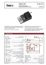
<strong>TAC</strong> <strong>Venta</strong> <strong>V211</strong><br />
Two-way Plug Valve, Flanged<br />
PN 16 (232 psi)<br />
F-<strong>20</strong>-<strong>60</strong><br />
19 Nov <strong>20</strong>03<br />
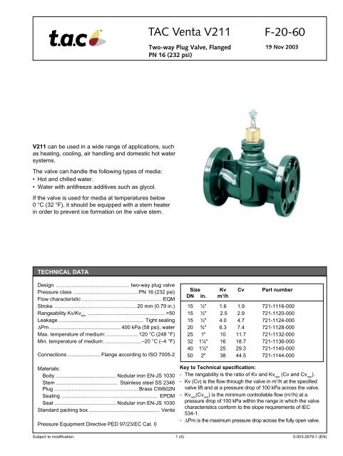
<strong>V211</strong> can be used in a wide range of applications, such<br />
as heating, cooling, air handling and domestic hot water<br />
systems.<br />
The valve can handle the following types of media:<br />
• Hot and chilled water.<br />
• Water with antifreeze additives such as glycol.<br />
If the valve is used for media at temperatures below<br />
0 °C (32 °F), it should be equipped with a stem heater<br />
in order to prevent ice formation on the valve stem.<br />
TECHNICAL DATA<br />
Design ................................................... two-way plug valve<br />
Pressure class ............................................. PN 16 (232 psi)<br />
Flow characteristic ........................................................EQM<br />
Stroke ......................................................... <strong>20</strong> mm (0.79 in.)<br />
Rangeability Kv/Kv min<br />
...................................................... >50<br />
Leakage ........................................................... Tight sealing<br />
∆Pm ................................................. 400 kPa (58 psi), water<br />
Max. temperature of medium: ...................... 1<strong>20</strong> °C (248 °F)<br />
Min. temperature of medium: ......................... –<strong>20</strong> °C (–4 °F)<br />
Connections ....................... Flange according to ISO 7005-2<br />
Materials:<br />
Body .......................................... Nodular iron EN-JS 1030<br />
Stem ........................................... Stainless steel SS 2346<br />
Plug .......................................................... Brass CW<strong>60</strong>2N<br />
Sealing ................................................................... EPDM<br />
Seat ........................................... Nodular iron EN-JS 1030<br />
Standard packing box ................................................. <strong>Venta</strong><br />
Pressure Equipment Directive PED 97/23/EC Cat. 0<br />
Size Kv Cv Part number<br />
DN in. m 3 /h<br />
15 ½" 1.6 1.9 721-1116-000<br />
15 ½" 2.5 2.9 721-11<strong>20</strong>-000<br />
15 ½" 4.0 4.7 721-1124-000<br />
<strong>20</strong> ¾" 6.3 7.4 721-1128-000<br />
25 1" 10 11.7 721-1132-000<br />
32 1¼" 16 18.7 721-1136-000<br />
40 1½" 25 29.3 721-1140-000<br />
50 2" 38 44.5 721-1144-000<br />
Key to Technical specification:<br />
- The rangability is the ratio of Kv and Kv min<br />
(Cv and Cv min<br />
).<br />
- Kv (Cv) is the flow through the valve in m 3 /h at the specified<br />
valve lift and at a pressure drop of 100 kPa across the valve.<br />
- Kv min<br />
(Cv min<br />
) is the minimum controllable flow (m 3 /h) at a<br />
pressure drop of 100 kPa within the range in which the valve<br />
characteristics conform to the slope requirements of IEC<br />
534-1.<br />
- ∆Pm is the maximum pressure drop across the fully open valve.<br />
Subject to modification.<br />
1 (4) 0-003-2679-1 (EN)
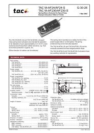
DESIGN AND CHARACTERISTICS<br />
The design of the <strong>V211</strong> gives good resistance against solid<br />
particles in the fluid.<br />
The plug is guided throughout the lift, which reduces the risk<br />
for vibrations. The valve closes with the stem up.<br />
The flow characteristics of the <strong>V211</strong> is equal percentage<br />
modified.<br />
Flow<br />
100<br />
80<br />
<strong>60</strong><br />
A<br />
40<br />
<strong>20</strong><br />
0<br />
0 <strong>20</strong> 40 <strong>60</strong> 80 100<br />
Installed characteristics β = 0,5<br />
Relative<br />
valve lift<br />
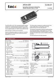
CAVITATIONS<br />
Cavitation takes place in a valve when the velocity of the flow<br />
between the plug and seat increases to the extent that gas<br />
bubbles are created in the water.<br />
When, after the plug and seat, the velocity decreases, the gas<br />
bubbles collapse (implode), generating conciderable noise<br />
and causing conciderable wear on the valve.<br />
By means of the cavitation diagram shown in the figure it can<br />
be checked if risk of cavitation exists with the working<br />
conditions in the pertinent installation.<br />
Proceed as follows: Using the static pressure before the valve<br />
(e.g. 1000 kPa), plot the horizontal line to the line for the<br />
temperature of the liquide (e.g. 1<strong>20</strong> °C).<br />
From the intersection point, plot a vertical line downwards and<br />
read off the max.permissible pressure drop across the valve.<br />
If the computed pressure drop exceeds the value read from<br />
the diagram there is risk for cavitation.<br />
Pressure drop chart at the beginning of cavitation<br />
PSI<br />
232<br />
<strong>20</strong>3<br />
174<br />
145<br />
116<br />
87<br />
58<br />
29<br />
0<br />
(kPa) Static pressure before valve<br />
1<strong>60</strong>0<br />
1400<br />
1<strong>20</strong>0<br />
1000<br />
800<br />
<strong>60</strong>0<br />
400<br />
<strong>20</strong>0<br />
0<br />
0<br />
0<br />
100<br />
14,5<br />
<strong>20</strong>0<br />
29<br />
300<br />
43,5<br />
1<strong>60</strong>°C (3<strong>20</strong>°F)<br />
140°C (284°F)<br />
1<strong>20</strong>°C (248°F)<br />
100°C (212°F)<br />
80°C (176°F)<br />
<strong>20</strong>°C (68°F)<br />
400 500 <strong>60</strong>0 kPa<br />
58 72,5 87 PSI<br />
Pressure drop over valve<br />
Pressure drop limit where caviation might occur. Is dependent of valve<br />
inlet pressure and temperature of water.<br />
0-003-2679-1 (EN)<br />
2 (4)
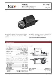
SPECIFICATION OF ACTUATOR<br />
Use the diagram below to select actuator motor for the <strong>V211</strong><br />
to close required ∆Pc. A suitable actuator is selected, using<br />
the data sheet F-10-6.<br />
Actuator power<br />
lbf<br />
N<br />
450<br />
400<br />
<strong>20</strong>00<br />
1800<br />
DN50 DN40 DN32<br />
2" 1½" 1¼"<br />
DN25<br />
1"<br />
350<br />
300<br />
250<br />
<strong>20</strong>0<br />
1<strong>60</strong>0<br />
1400<br />
1<strong>20</strong>0<br />
1000<br />
800<br />
DN<strong>20</strong><br />
¾"<br />
DN15<br />
½"<br />
DN15/10<br />
M800<br />
(close)<br />
150<br />
<strong>60</strong>0<br />
100<br />
400<br />
M400,<br />
M310<br />
50<br />
<strong>20</strong>0<br />
0<br />
0<br />
0<br />
500 1000 1500 <strong>20</strong>00 2500<br />
∆P c<br />
kPa<br />
0 50 100 150 <strong>20</strong>0 250 300 350<br />
PSI<br />
INSTALLATION<br />
The valve should be mounted with flow<br />
direction in accordance with the valve<br />
marking.<br />
It is recommended to install the valve in<br />
the return pipe, in order to avoid<br />
exposing the actuator to high<br />
temperatures.<br />
The valve must not be installed with the<br />
actuator mounted below the valve.<br />
To ensure that suspended solids will not<br />
become jammed between the valve<br />
plug and seat, a filter should be installed<br />
upstream of the valve, and the pipe<br />
system should be flushed before the<br />
valve is installed.<br />
A Typical installation without<br />
local circulating pump.<br />
To provide a good function, the<br />
pressure drop across the valve<br />
should be no less than half of the<br />
available pressure (∆P). This<br />
corresponds to a valve authority<br />
of 50%.<br />
∆P<br />
B Typical installation with local<br />
circulating pump.<br />
The K V<br />
(C V<br />
) value of the valve to<br />
be selected so that the entire<br />
available pressure drop (∆P) falls<br />
across the control valve.<br />
∆P<br />
3 (4) 0-003-2679-1 (EN)
PRESSURE DROP CHART<br />
Press. drop<br />
psi kPa<br />
300 <strong>20</strong>00<br />
Capacity Cv 0,3 0,5 0,7 1,2 1,9 2,9 4,7 7,4 12 19 29 45<br />
Kv (m /h at ∆p=100 kPa) 0,25 0,4 0,63 1,0 1,6 2,5 4 6,3 10 16 25 40<br />
<strong>20</strong>0<br />
1500<br />
150 1000<br />
800<br />
100<br />
<strong>60</strong>0<br />
80<br />
500<br />
<strong>60</strong> 400<br />
50<br />
300<br />
40<br />
30<br />
<strong>20</strong>0<br />
<strong>20</strong><br />
10<br />
8<br />
7<br />
6<br />
5<br />
4<br />
3<br />
100<br />
80<br />
70<br />
<strong>60</strong><br />
50<br />
40<br />
30<br />
<strong>20</strong><br />
2<br />
1<br />
0,8<br />
0,7<br />
0,6<br />
0,5<br />
0,4<br />
0,3<br />
10<br />
8<br />
7<br />
6<br />
5<br />
4<br />
3<br />
2<br />
0,2<br />
1<br />
0,01 0,02 0,03 0,04 0,06 0,08 0,1 0,2 0,3 0,4 0,5 0,8 1 2 3 4 5 6 7 8 9 10 <strong>20</strong> 30 40 50 <strong>60</strong> 80 100 l/s<br />
0,2 0,3 0,4 0,5 0,8 1,0 2 3 4 5 6 8 10 <strong>20</strong> 30 40 50 80 100 <strong>20</strong>0 300 500 1000<br />
gpm<br />
Flow<br />
DIMENSIONS AND WEIGHT<br />
SPARE PARTS<br />
D<br />
M8<br />
E<br />
C<br />
Stuffing box<br />
Standard type S .................................. max 150 °C (302 °F)<br />
Item number ................................................... 1-001-0800-0<br />
H<br />
G<br />
F<br />
B<br />
A<br />
Part Conn. Dimensions Weight<br />
No A B C D E F G H<br />
721- DN In. mm In. mm In. mm In. mm In. mm In. mm In. mm In. mm In. kg lb.<br />
1116 15 ½ 130 5.12 41.5 1.64 123 4.84 4x14 4x0.55 <strong>20</strong> 0.79 38 1.50 95 3.74 65 2.56 2.1 4.6<br />
11<strong>20</strong> 15 ½ 130 5.12 41.5 1.64 123 4.84 4x14 4x0.55 <strong>20</strong> 0.79 38 1.50 95 3.74 65 2.56 2.1 4.6<br />
1124 15 ½ 130 5.12 41.5 1.64 123 4.84 4x14 4x0.55 <strong>20</strong> 0.79 38 1.50 95 3.74 65 2.56 2.1 4.6<br />
1128 <strong>20</strong> ¾ 150 5.91 43.5 1.71 126 4.96 4x14 4x0.55 <strong>20</strong> 0.79 41 1.61 105 4.13 75 2.95 2.6 5.7<br />
1132 25 1 1<strong>60</strong> 6.30 44 1.73 131 5.16 4x14 4x0.55 <strong>20</strong> 0.79 46 1.81 115 4.53 85 3.35 3.2 7.1<br />
1136 32 1¼ 180 7.09 58.5 2.30 144.5 5.69 4x19 4x0,75 <strong>20</strong> 0.79 59.5 2.34 140 5.51 100 3.94 4.6 10.1<br />
1140 40 1½ <strong>20</strong>0 7.87 <strong>60</strong>.5 2.38 146 5.75 4x19 4x0,75 <strong>20</strong> 0.79 61 2.40 150 5.91 110 4.33 5.8 12.8<br />
1144 50 2 230 9.06 74.5 2.93 161 9.34 4x19 4x0,75 <strong>20</strong> 0.79 76 3.00 165 6.50 125 4.92 8.0 17.6<br />
Trademarks and registered trademarks are the property of their respective owners.<br />
<strong>TAC</strong> Vista ® , <strong>TAC</strong> Menta ® , <strong>TAC</strong> Xenta ® and <strong>TAC</strong> I-talk ® are registered trademarks of <strong>TAC</strong> AB. LonMark ® and LonWorks ® are registered trademarks of the Echelon Corporation.<br />
Windows ® is a registered trademark of Microsoft.<br />
www.tac.com<br />
0-003-2679-1 (EN)<br />
4 (4)