G-30-26 TAC M-AF24/AF24-S TAC M-AF230/AF230-S
G-30-26 TAC M-AF24/AF24-S TAC M-AF230/AF230-S
G-30-26 TAC M-AF24/AF24-S TAC M-AF230/AF230-S

Create successful ePaper yourself
Turn your PDF publications into a flip-book with our unique Google optimized e-Paper software.
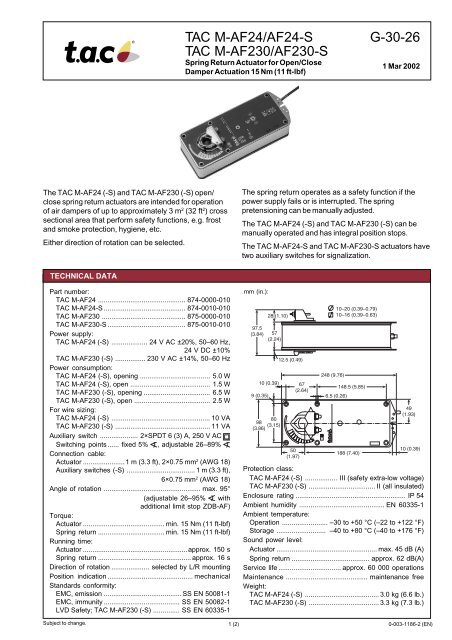
1<strong>TAC</strong> M-<strong>AF24</strong>/<strong>AF24</strong>-S<strong>TAC</strong> M-AF2<strong>30</strong>/AF2<strong>30</strong>-SSpring Return Actuator for Open/CloseDamper Actuation 15 Nm (11 ft-lbf)G-<strong>30</strong>-<strong>26</strong>1 Mar 2002The <strong>TAC</strong> M-<strong>AF24</strong> (-S) and <strong>TAC</strong> M-AF2<strong>30</strong> (-S) open/close spring return actuators are intended for operationof air dampers of up to approximately 3 m 2 (32 ft 2 ) crosssectional area that perform safety functions, e.g. frostand smoke protection, hygiene, etc.Either direction of rotation can be selected.The spring return operates as a safety function if thepower supply fails or is interrupted. The springpretensioning can be manually adjusted.The <strong>TAC</strong> M-<strong>AF24</strong> (-S) and <strong>TAC</strong> M-AF2<strong>30</strong> (-S) can bemanually operated and has integral position stops.The <strong>TAC</strong> M-<strong>AF24</strong>-S and <strong>TAC</strong> M-AF2<strong>30</strong>-S actuators havetwo auxiliary switches for signalization.TECHNICAL DATAPart number:<strong>TAC</strong> M-<strong>AF24</strong> .............................................. 874-0000-010<strong>TAC</strong> M-<strong>AF24</strong>-S ........................................... 874-0010-010<strong>TAC</strong> M-AF2<strong>30</strong> ............................................ 875-0000-010<strong>TAC</strong> M-AF2<strong>30</strong>-S ......................................... 875-0010-010Power supply:<strong>TAC</strong> M-<strong>AF24</strong> (-S) ................... 24 V AC ±20%, 50–60 Hz,24 V DC ±10%<strong>TAC</strong> M-AF2<strong>30</strong> (-S) ................ 2<strong>30</strong> V AC ±14%, 50–60 HzPower consumption:<strong>TAC</strong> M-<strong>AF24</strong> (-S), opening ..................................... 5.0 W<strong>TAC</strong> M-<strong>AF24</strong> (-S), open .......................................... 1.5 W<strong>TAC</strong> M-AF2<strong>30</strong> (-S), opening ................................... 6.5 W<strong>TAC</strong> M-AF2<strong>30</strong> (-S), open ........................................ 2.5 WFor wire sizing:<strong>TAC</strong> M-<strong>AF24</strong> (-S) .................................................... 10 VA<strong>TAC</strong> M-AF2<strong>30</strong> (-S) .................................................. 11 VAAuxiliary switch .................... 2×SPDT 6 (3) A, 250 V ACSwitching points ...... fixed 5% , adjustable <strong>26</strong>–89%Connection cable:Actuator ......................1 m (3.3 ft), 2×0.75 mm 2 (AWG 18)Auxiliary switches (-S) .................................... 1 m (3.3 ft),6×0.75 mm 2 (AWG 18)Angle of rotation ................................................... max. 95°(adjustable <strong>26</strong>–95% withadditional limit stop ZDB-AF)Torque:Actuator ........................................... min. 15 Nm (11 ft-lbf)Spring return ................................... min. 15 Nm (11 ft-lbf)Running time:Actuator .......................................................approx. 150 sSpring return ................................................. approx. 16 sDirection of rotation .................... selected by L/R mountingPosition indication ............................................. mechanicalStandards conformity:EMC, emission ......................................... SS EN 50081-1EMC, immunity ........................................ SS EN 50082-1LVD Safety; <strong>TAC</strong> M-AF2<strong>30</strong> (-S) .............. SS EN 60335-1mm (in.):9 (0.35)28 (1.10)97.5(3.84) 57(2.24)10 (0.39)8098(3.15)(3.86)12.5 (0.49)+.8.6.450(1.97)67(2.64).2A 0L248 (9.76)10–20 (0.39–0.79)10–16 (0.39–0.63)148.5 (5.85)6.5 (0.<strong>26</strong>)188 (7.40)49(1.93)10 (0.39)Protection class:<strong>TAC</strong> M-<strong>AF24</strong> (-S) ................. III (safety extra-low voltage)<strong>TAC</strong> M-AF2<strong>30</strong> (-S) ................................... II (all insulated)Enclosure rating .......................................................... IP 54Ambient humidity ............................................. EN 60335-1Ambient temperature:Operation ........................ –<strong>30</strong> to +50 °C (–22 to +122 °F)Storage .......................... –40 to +80 °C (–40 to +176 °F)Sound power level:Actuator ..................................................... max. 45 dB (A)Spring return ......................................... approx. 62 dB(A)Service life ................................. approx. 60 000 operationsMaintenance ........................................... maintenance freeWeight:<strong>TAC</strong> M-<strong>AF24</strong> (-S) ....................................... 3.0 kg (6.6 lb.)<strong>TAC</strong> M-AF2<strong>30</strong> (-S) ..................................... 3.3 kg (7.3 lb.)Subject to change.1 (2) 0-003-1186-2 (EN)
WIRING DIAGRAM<strong>TAC</strong> M-<strong>AF24</strong> (-S): Connect viasafety isolating transformer.!<strong>TAC</strong> M-AF2<strong>30</strong> (-S): To isolatefrom the main power supply,the system must incorporate a devicewhich provides all-pole disconnection(with at least a 3 mm (0.12 in.) contactgap).Parallel connection of several actuatorsis possible. Power consumption must beobserved.(G0)(G)N L11 2(24 V AC/DC)2<strong>30</strong> V ACS1 S2 S3 S4 S5 S6MA = 5 %< A < B> A > BB = <strong>26</strong> ... 89 %<strong>TAC</strong> M-<strong>AF24</strong>-S,<strong>TAC</strong> M-AF2<strong>30</strong>-SM<strong>TAC</strong> M-<strong>AF24</strong>,<strong>TAC</strong> M-AF2<strong>30</strong>MODE OF OPERATIONThe actuator is fitted with a universalspindle clamp for quick and easy mountingdirectly onto the damper spindle. Theactuator is also supplied with an antirotationstrap for fixing it in position. Thedirection of rotation is selected bymounting left or right.The damper can be operated manuallyand locked in the required position.Release of the locking mechanism can beachieved manually or automatically byapplying the supply voltage.The actuator moves the damper to itsnormal working position while tensioningthe return spring at the same time.If the power supply is interrupted, theenergy stored in the spring moves thedamper back to its safe position ≤ 0°.The actuator is supplied from factory with5° of pretensioning. The pretensioningcan be unlocked manually by means of acrank or electrically by connecting thepower supply. The actuator will then bemoved back to its safe position ≤ 0°.The actuator is overload-proof and needsno limit switches. It stops automatically atthe end stops.VARIABLE END SWITCHThe <strong>TAC</strong> M-<strong>AF24</strong>(2<strong>30</strong>)-S actuator hasone fixed auxiliary switch and one adjustableauxiliary switch which allows anangle of rotation of 5° and between <strong>26</strong>and 89% to be signalled.NOTEWhen calculating the torque required tooperate dampers, it is essential to takeinto account all the data supplied by thedamper manufacturer concerning crosssectional area, design, mounting and airflow conditions.ACCESSORIESPlease refer to data sheet G-<strong>30</strong>-90 “AccessoriesDamper Actuators” (part. no. 0-003-22551).<strong>TAC</strong> AB, Jägershillgatan 18, SE-213 75 MALMÖ, SWEDEN, +46 40 38 68 50 (switchboard), www.tac-global.com0-003-1186-2 (EN) 2 (2)