Practical Advantages of the Rhodotron - Electron Beam and X-ray ...
Practical Advantages of the Rhodotron - Electron Beam and X-ray ...
Practical Advantages of the Rhodotron - Electron Beam and X-ray ...

You also want an ePaper? Increase the reach of your titles
YUMPU automatically turns print PDFs into web optimized ePapers that Google loves.
IBA Industrial - <strong>Practical</strong> <strong>Advantages</strong> <strong>of</strong> <strong>the</strong> <strong>Rhodotron</strong><br />
<strong>Practical</strong> <strong>Advantages</strong> <strong>of</strong> <strong>the</strong> <strong>Rhodotron</strong><br />
From its very beginnings, <strong>the</strong> <strong>Rhodotron</strong> electron beam accelerator was designed to be an industrial<br />
tool, to be used in industrial settings, <strong>and</strong> to demonstrate a reliability, flexibility, <strong>and</strong> operational<br />
economy that could meet <strong>and</strong> surpass <strong>the</strong> most strenuous <strong>of</strong> industrial dem<strong>and</strong>s. Using an<br />
elegantly simple design, <strong>the</strong> <strong>Rhodotron</strong> meets its design objectives, <strong>and</strong> <strong>of</strong>fers <strong>the</strong> world a truly<br />
unique departure from yesterday’s technology <strong>and</strong> limitations. From its low per kW cost to its built-in<br />
maintenance monitoring features, every aspect <strong>of</strong> <strong>the</strong> <strong>Rhodotron</strong> <strong>and</strong> its subsystems demonstrates<br />
unfaltering attention to practical efficiencies, ease <strong>of</strong> use, <strong>and</strong> operational superiority.<br />
The practical advantages discussed in this article focus on <strong>the</strong> accelerator’s performance <strong>and</strong><br />
features as <strong>the</strong>y would be viewed in <strong>the</strong> eyes <strong>of</strong> a seasoned accelerator user <strong>and</strong> <strong>the</strong> facility’s<br />
management. Of key interest are features such as electrical efficiency, ease <strong>and</strong> speed <strong>of</strong><br />
maintenance, overall reliability, <strong>and</strong> flexibility in terms <strong>of</strong> matching capacity to production dem<strong>and</strong>s.<br />
Whe<strong>the</strong>r for use in sterilization, polymer modification, pulp processing, cold pasteurization <strong>of</strong> food,<br />
or basic research, <strong>the</strong>se practical advantages cannot be overlooked.<br />
RESERVE POWER AND ECONOMY<br />
Operating in a continuous wave (CW) mode <strong>and</strong> with<br />
three basic models to choose from, <strong>the</strong> <strong>Rhodotron</strong>’s<br />
guaranteed ratings for beam power at 10 MeV<br />
are not only conservative but represent <strong>the</strong> widest<br />
demonstrated range available in today’s industrial<br />
processing market.<br />
The smallest <strong>Rhodotron</strong> currently available is <strong>the</strong> model<br />
TT100, with a guaranteed power rating <strong>of</strong> 25 / 45 kW.<br />
The intermediate unit, <strong>the</strong> TT200 has a guaranteed<br />
power rating <strong>of</strong> 50 / 80 kW. The model TT300 is<br />
guaranteed at 190 kW. All three models have been built<br />
<strong>and</strong> shipped to customers throughout <strong>the</strong> world.<br />
On <strong>the</strong> high powered end with up to 200 kW <strong>of</strong> beam<br />
power, <strong>the</strong> <strong>Rhodotron</strong> model TT300 is several times<br />
more powerful than any o<strong>the</strong>r 10 MeV electron beam<br />
in operation today, yet in terms <strong>of</strong> capital cost per<br />
kW <strong>of</strong> beam capacity, it is less than 1/3 that <strong>of</strong> o<strong>the</strong>r<br />
technology sold. Additionally, even at 200 kW, it will<br />
operate with no more electrical power consumption<br />
than its linac counterpart at 50 kW.<br />
For lower power applications like in-house sterilization,<br />
<strong>the</strong> model TT100 is a scaled down version <strong>of</strong> <strong>the</strong><br />
original <strong>Rhodotron</strong>, with a smaller footprint <strong>and</strong> price<br />
tag to match. Even when <strong>the</strong> full 45 kW <strong>of</strong> beam<br />
capacity is not used, it remains extremely competitive in<br />
all aspects <strong>of</strong> economy….even when compared to units<br />
<strong>of</strong> less than ½ its kW rating! Moreover, this increased<br />
reserve <strong>of</strong> capacity means that short-sighted purchases<br />
can be avoided, <strong>and</strong> an in-house operation needing<br />
only 15 kW today will not need to repurchase in 5 or 10<br />
years time when <strong>the</strong>ir production doubles.<br />
ELECTRICAL EFFICIENCY<br />
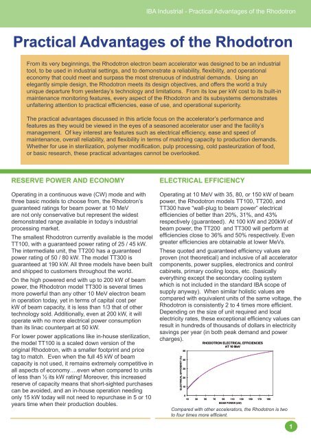
Operating at 10 MeV with 35, 80, or 150 kW <strong>of</strong> beam<br />
power, <strong>the</strong> <strong>Rhodotron</strong> models TT100, TT200, <strong>and</strong><br />
TT300 have “wall-plug to beam power” electrical<br />
efficiencies <strong>of</strong> better than 20%, 31%, <strong>and</strong> 43%<br />
respectively (guaranteed). At 100 kW <strong>and</strong> 200kW <strong>of</strong><br />
beam power, <strong>the</strong> TT200 <strong>and</strong> TT300 will perform at<br />
efficiencies close to 36% <strong>and</strong> 50% respectively. Even<br />
greater efficiencies are obtainable at lower MeVs.<br />
These quoted <strong>and</strong> guaranteed efficiency values are<br />
proven (not <strong>the</strong>oretical) <strong>and</strong> inclusive <strong>of</strong> all accelerator<br />
components, power supplies, electronics <strong>and</strong> control<br />
cabinets, primary cooling loops, etc. (basically<br />
everything except <strong>the</strong> secondary cooling system<br />
which is not included in <strong>the</strong> st<strong>and</strong>ard IBA scope <strong>of</strong><br />
supply anyway). When similar holistic values are<br />
compared with equivalent units <strong>of</strong> <strong>the</strong> same voltage, <strong>the</strong><br />
<strong>Rhodotron</strong> is consistently 2 to 4 times more efficient.<br />
Depending on <strong>the</strong> size <strong>of</strong> unit required <strong>and</strong> local<br />
electricity rates, <strong>the</strong>se exceptional efficiency values can<br />
result in hundreds <strong>of</strong> thous<strong>and</strong>s <strong>of</strong> dollars in electricity<br />
savings per year (in both peak dem<strong>and</strong> <strong>and</strong> power<br />
charges).<br />
ELECTRICAL EFFICIENCY (%)<br />
50<br />
40<br />
30<br />
20<br />
10<br />
RHODOTRON ELECTRICAL EFFICIENCIES<br />
AT 10 MeV<br />
0<br />
10 30 50 70 90 110 130 150 170 190<br />
BEAM POWER (kW)<br />
Compared with o<strong>the</strong>r accelerators, <strong>the</strong> <strong>Rhodotron</strong> is two<br />
to four times more efficient.<br />
1
IBA Industrial - <strong>Practical</strong> <strong>Advantages</strong> <strong>of</strong> <strong>the</strong> <strong>Rhodotron</strong><br />
NO KLYSTRON<br />
Because <strong>the</strong> <strong>Rhodotron</strong> operates in a continuous wave<br />
(CW) mode, it does not need a klystron to amplify <strong>the</strong><br />
accelerating RF signal. Instead, it uses a cathode<br />
driven tetrode which, by design, always operates at<br />
peak efficiency.<br />
Under normal operating conditions, <strong>the</strong> <strong>Rhodotron</strong>’s<br />
tetrode may have a useful life span up to 4 times<br />
that <strong>of</strong> a klystron installed in a similarly rated linac<br />
unit. Moreover, when a tetrode change is required,<br />
<strong>the</strong> new component will be readily available (unlike<br />
some klystrons), cost as little as 1/3 that <strong>of</strong> a new<br />
klystron, <strong>and</strong> depending on <strong>the</strong> accelerator’s design,<br />
could require many hours less to replace since in <strong>the</strong><br />
<strong>Rhodotron</strong> such replacements do not require breaking<br />
<strong>the</strong> vacuum in <strong>the</strong> acceleration cavity. Combined,<br />
<strong>the</strong>se direct <strong>and</strong> plant-time cost savings will add up<br />
dramatically over <strong>the</strong> service life <strong>of</strong> <strong>the</strong> unit.<br />
ELECTRON GUN USES A COMMON<br />
CATHODE- GRID ASSEMBLY<br />
The <strong>Rhodotron</strong>’s electron gun uses <strong>the</strong> same type <strong>of</strong><br />
st<strong>and</strong>ard cathode <strong>and</strong> grid assembly that is commonly<br />
found in small UHF electron tubes (planar triodes). As<br />
such, it has been well tested <strong>and</strong> refined in industrial<br />
settings. It is low in maintenance <strong>and</strong> replacement<br />
cost, <strong>and</strong> abundant in supply when <strong>the</strong> time comes for<br />
it to be replaced.<br />
FLEXIBILITY IN BEAM VOLTAGE<br />
Supplied as optional configurations, <strong>the</strong>re are several<br />
ways in which <strong>the</strong> <strong>Rhodotron</strong> can be configured so<br />
as to provide different beam voltages (MeV) from <strong>the</strong><br />
same unit. The unit may be supplied with 2 beam lines<br />
<strong>and</strong> scan horns, each exiting at different ports <strong>of</strong> <strong>the</strong><br />
accelerator cavity (eg. for 5 <strong>and</strong> 10 MeV beams), or<br />
<strong>the</strong> RF field within <strong>the</strong> cavity can be modified so as to<br />
reduce <strong>the</strong> beam voltage at a given port by up to 30%<br />
(eg. using <strong>the</strong> 10 MeV beam line at 7 MeV).<br />
Within limits, such configuration modifications can be<br />
done with a conservation <strong>of</strong> total beam power (eg. 80<br />
kW <strong>of</strong> beam at ei<strong>the</strong>r 10 MeV <strong>and</strong> 8 mA or 8 MeV at<br />
10 mA), <strong>and</strong> in some cases, reduction <strong>of</strong> <strong>the</strong> MeV at a<br />
given port can even increase overall power efficiency.<br />
This degree <strong>of</strong> flexibility <strong>and</strong> power preservation is<br />
rare in most linac systems. It is however a boon to <strong>the</strong><br />
<strong>Rhodotron</strong> user, whom if faced with a product change<br />
requiring less penetration voltage, has <strong>the</strong> option to<br />
“capture” <strong>the</strong> gains <strong>of</strong> <strong>the</strong> lower voltage setting in <strong>the</strong><br />
form <strong>of</strong> improved throughput opportunities (line speed<br />
is related to mA). Additionally, this feature enhances<br />
<strong>the</strong> resale value <strong>of</strong> <strong>the</strong> <strong>Rhodotron</strong> (for example,<br />
when an owner is ready to purchase an even larger<br />
<strong>Rhodotron</strong>) because it opens up a wider range <strong>of</strong><br />
potential new owners for <strong>the</strong> system (i.e. not restricted<br />
to those needing just a 10 MeV machine).<br />
EASY TO COOL<br />
The <strong>Rhodotron</strong> <strong>of</strong>fers <strong>the</strong><br />
possibility to have several<br />
beamlines at different<br />
energies.<br />
Possibly one <strong>of</strong> <strong>the</strong> greatest concerns for a high<br />
powered linac designer or operator is that <strong>of</strong><br />
waveguide cooling <strong>and</strong> temperature regulation. This is<br />
because <strong>of</strong> <strong>the</strong> double edged sword that is inherent to<br />
linacs.<br />
Linac waveguides are relatively small <strong>and</strong> have an<br />
extremely high power to surface area ratio (in <strong>the</strong><br />
range <strong>of</strong> Megawatts/square meter during a pulse),<br />
which, when it comes to cooling, means that <strong>the</strong>y<br />
operate at very high temperatures <strong>and</strong> require<br />
immense amounts <strong>of</strong> coolant flow. Inadequate cooling<br />
system design, air bubbles in <strong>the</strong> coolant, or faults in<br />
<strong>the</strong> primary or secondary cooling system, can all spell<br />
disaster for some types <strong>of</strong> linacs. Hot spots within<br />
<strong>the</strong> tube, sometimes developing within seconds, have<br />
been known to melt waveguides.<br />
Ano<strong>the</strong>r problem with conventional linacs <strong>and</strong> <strong>the</strong>ir<br />
cooling is that <strong>the</strong>y must usually operate in a very<br />
narrow temperature range, <strong>of</strong>ten as small as plus or<br />
minus 0.5 degrees Celsius. This is because as <strong>the</strong><br />
waveguide heats up, its metallic structure exp<strong>and</strong>s<br />
<strong>and</strong> this changes <strong>the</strong> resonant frequency <strong>of</strong> each<br />
small cavity. This results in mismatches <strong>and</strong> power<br />
reflections between <strong>the</strong> waveguide <strong>and</strong> <strong>the</strong> klystron.<br />
Both <strong>of</strong> <strong>the</strong>se problems are virtually eliminated with<br />
<strong>the</strong> <strong>Rhodotron</strong>’s unique radial metric wavelength<br />
design. Instead <strong>of</strong> dissipating power (heating) over<br />
a small surface area, <strong>the</strong> interior wall surface area <strong>of</strong><br />
<strong>the</strong> <strong>Rhodotron</strong>’s accelerating cavity is several orders<br />
<strong>of</strong> magnitude larger than that <strong>of</strong> a linac. Heating is<br />
proportionately less severe, moreover, ordinary water<br />
is used as <strong>the</strong> coolant to <strong>the</strong> <strong>Rhodotron</strong> structures.<br />
On <strong>the</strong> issue <strong>of</strong> heat regulation, <strong>the</strong> <strong>Rhodotron</strong> can<br />
operate within a temperature window <strong>of</strong> about 5<br />
degrees Celsius. This is because <strong>the</strong> frequency source<br />
2
IBA Industrial - <strong>Practical</strong> <strong>Advantages</strong> <strong>of</strong> <strong>the</strong> <strong>Rhodotron</strong><br />
<strong>of</strong> <strong>the</strong> <strong>Rhodotron</strong> is linked by an electronic circuit to<br />
<strong>the</strong> resonant frequency <strong>of</strong> <strong>the</strong> cavity. When <strong>the</strong> cavity<br />
exp<strong>and</strong>s due to temperature changes, <strong>the</strong> frequency<br />
source follows automatically to maintain perfect tune.<br />
To <strong>the</strong> end user, this means that <strong>the</strong> <strong>Rhodotron</strong> is a nontemperamental<br />
machine, <strong>and</strong> that its expected reliability<br />
(up-time availability) is significantly greater.<br />
COMPACT<br />
With a model TT100 footprint <strong>of</strong> only 1.6 meters<br />
in diameter <strong>and</strong> a height <strong>of</strong> about 1.75 meters, <strong>the</strong><br />
<strong>Rhodotron</strong> is far <strong>and</strong> away <strong>the</strong> most compact electron<br />
beam accelerator in its class. Over <strong>and</strong> above lending<br />
itself to easy maintenance, <strong>the</strong> compact nature <strong>of</strong> <strong>the</strong><br />
<strong>Rhodotron</strong> serves to significantly reduce <strong>the</strong> amount<br />
<strong>of</strong> shielding required to house it. Compared to some<br />
accelerators <strong>of</strong> equal or lesser voltage <strong>and</strong> power,<br />
<strong>the</strong> petite size <strong>of</strong> <strong>the</strong> <strong>Rhodotron</strong> can, in some plant<br />
configurations, reduce shielding expense by as much<br />
as 30% or more. Its low pr<strong>of</strong>ile also lends itself to vault<br />
<strong>and</strong> building constraints where local codes limit building<br />
heights.<br />
NON DIVERGING BEAM OUTPUT<br />
As an option, <strong>the</strong> <strong>Rhodotron</strong> can be supplied with a<br />
two-staged scan horn system that delivers a scanned<br />
but non-diverging (parallel <strong>ray</strong>) beam. The first section<br />
<strong>of</strong> <strong>the</strong> scan assembly is a typical triangular-shaped scan<br />
horn which scans <strong>the</strong> beam spot back <strong>and</strong> forth in a<br />
uniform yet divergent pattern. At <strong>the</strong> window end <strong>of</strong> <strong>the</strong><br />
scan horn is a second bending magnet assembly that<br />
reorients <strong>the</strong> electrons, so that <strong>the</strong> resultant beam is<br />
non-divergent.<br />
The <strong>Rhodotron</strong> scan horn system<br />
provides excellent dose uniformity.<br />
This unique <strong>Rhodotron</strong> scan horn option provides<br />
several major advantages in both <strong>the</strong> uniformity <strong>of</strong> dose<br />
delivery <strong>and</strong> <strong>the</strong> efficiency <strong>of</strong> beam utilization.<br />
The non-divergent beam allows for a better fit between<br />
<strong>the</strong> top surface <strong>of</strong> <strong>the</strong> product to be processed <strong>and</strong> <strong>the</strong><br />
path <strong>of</strong> <strong>the</strong> electrons passing near <strong>the</strong> edges <strong>of</strong> that<br />
surface. In conventional scanning systems <strong>the</strong>re is an<br />
angle <strong>of</strong> incidence at <strong>the</strong> edge <strong>of</strong> <strong>the</strong> beam scan which<br />
is not at right angles to <strong>the</strong> treated surface. This means<br />
that <strong>the</strong> edge electrons are directed to clip through <strong>the</strong><br />
corners <strong>of</strong> <strong>the</strong> treatment volume <strong>and</strong> deposit most <strong>of</strong><br />
<strong>the</strong>ir energy outside <strong>of</strong> <strong>the</strong> product volume. In beam<br />
assemblies with wide solid angles, this can reduce <strong>the</strong><br />
effective efficiency <strong>of</strong> beam utilization by as much as<br />
15%. This waste is avoided using <strong>the</strong> <strong>Rhodotron</strong>’s nondivergent<br />
scan system.<br />
As a conventional beam diverges, <strong>the</strong> dose rate at<br />
fur<strong>the</strong>r planes drops because <strong>the</strong> beam is spread out<br />
over a wider area. In some configurations, especially<br />
where <strong>the</strong> divergence angle is large or where <strong>the</strong> scan<br />
apex to product surface distance is small, this means<br />
that <strong>the</strong> surface dose can be greatly affected by small<br />
changes in distance to <strong>the</strong> window. Moreover, it means<br />
that at depths deep to <strong>the</strong> product surface, <strong>the</strong>re is an<br />
added element forcing a wider max to min dose ratio.<br />
Again, both <strong>of</strong> <strong>the</strong>se effects are minimized with <strong>the</strong><br />
<strong>Rhodotron</strong>’s non-divergent beam option.<br />
Finally, with all <strong>the</strong> electrons coming towards <strong>the</strong> product<br />
in a pseudo-coherent pattern, <strong>the</strong> electrons hitting <strong>the</strong><br />
product at <strong>the</strong> edges <strong>of</strong> <strong>the</strong> product volume are doing<br />
so in <strong>the</strong> same manner as <strong>the</strong>y are in <strong>the</strong> center <strong>of</strong> <strong>the</strong><br />
beam. This means that <strong>the</strong> “cosine effect” which is<br />
sometimes seen in product-beam configurations that<br />
optimize beam utilization will no longer be evident. As a<br />
result, tighter max/min dose ratios are expected.<br />
ASSYMETRICAL SCANNING<br />
As an option, <strong>the</strong> <strong>Rhodotron</strong> can be supplied with<br />
an adjustable <strong>of</strong>f-set <strong>of</strong> <strong>the</strong> center <strong>of</strong> <strong>the</strong> scan. For<br />
certain facility configurations using a horizontal beam to<br />
irradiate products passing beside (not under) <strong>the</strong> beam,<br />
this is a major advantage. Likewise, for certain special<br />
applications in <strong>the</strong> vertical mode, <strong>the</strong> ability to shift <strong>the</strong><br />
beam (combined with <strong>the</strong> st<strong>and</strong>ard feature <strong>of</strong> a variable<br />
scan width setting from 30 to 100%) is useful.<br />
When processing horizontally, <strong>the</strong> base <strong>of</strong> <strong>the</strong> product<br />
carrier is usually fixed, <strong>and</strong> thus to treat products at that<br />
position on <strong>the</strong> carrier, <strong>the</strong> beam has to be scanned at<br />
<strong>the</strong> maximum setting. If <strong>the</strong> full height <strong>of</strong> <strong>the</strong> carrier is<br />
filled with product, this is fine, however, if <strong>the</strong> full height<br />
<strong>of</strong> <strong>the</strong> carrier is not used, <strong>the</strong>n empty space has to be<br />
3
IBA Industrial - <strong>Practical</strong> <strong>Advantages</strong> <strong>of</strong> <strong>the</strong> <strong>Rhodotron</strong><br />
irradiated. By both reducing <strong>the</strong> scan setting, <strong>and</strong> <strong>the</strong>n<br />
<strong>of</strong>f-setting <strong>the</strong> center <strong>of</strong> <strong>the</strong> scan downwards, <strong>the</strong>re is<br />
no need to waste beam in empty space.<br />
CW MEANS UNRESTRICTED SCAN FREQUENCY<br />
Unlike most linac systems, <strong>the</strong> CW beam current <strong>of</strong> <strong>the</strong><br />
<strong>Rhodotron</strong> eliminates <strong>the</strong> restraint <strong>of</strong> a low scanning<br />
frequency (typically set at about 5 Hz for most linacs).<br />
The <strong>Rhodotron</strong>’s beam is scanned back <strong>and</strong> forth at a<br />
minimum rate <strong>of</strong> 100 Hz or more (optionally at 200 Hz).<br />
This ability to scan at a higher frequency generates a<br />
more uniform distribution <strong>of</strong> dose over <strong>the</strong> width <strong>of</strong> <strong>the</strong><br />
beam scan, <strong>and</strong> prohibits <strong>the</strong> possibility <strong>of</strong> getting a<br />
“zig-zag” or “zebra-stripes” dose pattern appearing on<br />
<strong>the</strong> product when it is treated to very low doses at low<br />
beam power <strong>and</strong> high conveyance speeds. Additionally<br />
<strong>the</strong> scanning signals <strong>of</strong> <strong>the</strong> <strong>Rhodotron</strong> are specially<br />
modulated to provide very steep fall-<strong>of</strong>fs at <strong>the</strong> beam<br />
edge, without <strong>the</strong> “horn artifacts” commonly seen in<br />
many o<strong>the</strong>r types <strong>of</strong> electron scanning systems.<br />
CW MEANS A WIDER CHOICE OF BEAM CURRENT<br />
Conventional linacs regulate <strong>the</strong>ir beam current by<br />
modifying a combination <strong>of</strong> variables such as <strong>the</strong><br />
peak beam current during a pulse, <strong>the</strong> rep rate (how<br />
many beam pulses are triggered each second), <strong>and</strong><br />
<strong>the</strong> pulse width (how long <strong>the</strong> beam is on for each<br />
pulse). Linac rep rates are relatively limited (on <strong>the</strong><br />
order <strong>of</strong> 1000 pulses per second, <strong>and</strong> usually much<br />
less), <strong>and</strong> for practical reasons, this limits <strong>the</strong> range <strong>of</strong><br />
averaged beam current (hence dose rates) available<br />
to <strong>the</strong> system. In <strong>the</strong> case <strong>of</strong> obtaining very low doses<br />
(for example, in dose setting <strong>and</strong> auditing procedures),<br />
<strong>the</strong>se restrictions <strong>of</strong>ten require special procedures <strong>and</strong><br />
bypass steps.<br />
With <strong>the</strong> CW <strong>of</strong> <strong>the</strong> <strong>Rhodotron</strong>, <strong>the</strong>re is no pulse rep<br />
rate or pulse width as seen with linacs. There is<br />
however an RF microstructure (always on for CW <strong>and</strong><br />
only on during <strong>the</strong> pulse for linacs). By analogy <strong>the</strong>n,<br />
<strong>the</strong> equivalent <strong>of</strong> “rep rate” is fixed at about 107.5<br />
million Hz or 215 million Hz (for <strong>the</strong> TT200/300 <strong>and</strong><br />
TT100 respectively). Fur<strong>the</strong>rmore while <strong>the</strong>re is no RF<br />
equivalent <strong>of</strong> “pulse width” in CW terms, for each <strong>of</strong> <strong>the</strong><br />
215 million RF cycles per second, electrons are only<br />
introduced into <strong>the</strong> RF field during <strong>the</strong> peak 1/6th <strong>of</strong><br />
<strong>the</strong> cycle. The variable used to modify beam current is<br />
<strong>the</strong> bias on <strong>the</strong> electron gun grid, <strong>and</strong> this is easily <strong>and</strong><br />
accurately regulated over a very wide range.<br />
In operational terms, this means that setting <strong>the</strong> system<br />
for low dose exposures can be done quickly, simply,<br />
very accurately, <strong>and</strong> without interruptions to <strong>the</strong> main<br />
production flow. Resolution <strong>of</strong> beam current settings is<br />
over 1000 steps <strong>of</strong> <strong>the</strong> full beam current, <strong>and</strong> optionally<br />
over 2000 steps. Current adjustments <strong>and</strong> settings can<br />
<strong>the</strong>refore be made in <strong>the</strong> order <strong>of</strong> a few micro-amps.<br />
TIGHTER CONTROL OF BEAM REGULATIONS<br />
Because it is operated in a CW mode without <strong>the</strong> need<br />
to match (synchronize) multiple trigger signals or worry<br />
about missed or mis-shaped pulses, <strong>the</strong> <strong>Rhodotron</strong><br />
is <strong>of</strong>fered with a guaranteed, self-regulating beam<br />
current stability <strong>of</strong> less than 0.5%. In statistical process<br />
control terms, this means that <strong>the</strong>re is considerably less<br />
uncertainty in <strong>the</strong> beam current compared to many linac<br />
systems (sometimes as high as 10%), <strong>and</strong> that tighter<br />
production tolerances can be set. Overall, this will mean<br />
less system fault interrupts in production, <strong>and</strong> both<br />
tighter <strong>and</strong> more consistent dosimetry results within <strong>and</strong><br />
between production runs.<br />
PROPORTIONAL BEAM CONTROL<br />
In routine production, absolute dose levels within <strong>the</strong><br />
product are controlled by <strong>the</strong> ratio between <strong>the</strong> beam<br />
current <strong>and</strong> <strong>the</strong> process line speed. This method,<br />
known as “proportional beam control”, allows for <strong>the</strong><br />
same dosing to be performed over a wide range <strong>of</strong><br />
beam current settings, by merely keeping <strong>the</strong> beam<br />
current to product speed ratio constant (e.g. running<br />
half speed at half current).<br />
While <strong>the</strong> ability to have proportionate beam control<br />
is not unique to <strong>the</strong> <strong>Rhodotron</strong>, <strong>the</strong>re is, however, a<br />
very important difference with <strong>the</strong> proportional beam<br />
control provided by <strong>the</strong> <strong>Rhodotron</strong>, all o<strong>the</strong>r linacs<br />
<strong>and</strong> most DC accelerators. Most proportional beam<br />
controls monitor <strong>the</strong> beam current <strong>and</strong> <strong>the</strong>n adjust<br />
for fluctuations <strong>and</strong>/or ramp-time changes in <strong>the</strong> mA<br />
by increasing or decreasing <strong>the</strong> product conveyance<br />
speed. This is because <strong>the</strong> accelerator beam currents<br />
are typically very slow to move from one non-zero<br />
current setting to ano<strong>the</strong>r.<br />
In <strong>Rhodotron</strong> technology, achieving <strong>and</strong> stabilizing<br />
beam current is done in <strong>the</strong> order <strong>of</strong> milliseconds, from<br />
any beam current setting to ano<strong>the</strong>r, over <strong>the</strong> entire<br />
operating range. In practical terms, what this means is<br />
that in proportional control mode, it is <strong>the</strong> conveyance<br />
speed which is monitored <strong>and</strong> it is <strong>the</strong> fast to respond<br />
mA that is modified. With this much improved method<br />
<strong>of</strong> keeping <strong>the</strong> ratio <strong>of</strong> beam current <strong>and</strong> conveyance<br />
speed constant, <strong>the</strong> dynamics <strong>of</strong> production <strong>and</strong> <strong>the</strong><br />
consistency <strong>of</strong> dosing is dramatically enhanced.<br />
Optimum matching <strong>of</strong> sterilization line speed with<br />
production conditions remote to <strong>the</strong> sterilization unit<br />
4
IBA Industrial - <strong>Practical</strong> <strong>Advantages</strong> <strong>of</strong> <strong>the</strong> <strong>Rhodotron</strong><br />
proper, translates to <strong>the</strong> ability to continuously monitor<br />
<strong>and</strong> “line balance” <strong>the</strong> entire production line, <strong>and</strong> to cost<br />
savings by generating <strong>and</strong> using only <strong>the</strong> beam power<br />
that is needed at any given point in time.<br />
NO MISSED PULSES<br />
RELATIVE INTENSITY<br />
100%<br />
75%<br />
50%<br />
25%<br />
RHODOTRON<br />
ENERGY SPREAD AROUND A 10 MeV PEAK<br />
Basic linac designs require that <strong>the</strong> RF in <strong>the</strong><br />
waveguide be intermittent (with proportionally long wait<br />
times between short “pulse-on times”) <strong>and</strong> perfectly<br />
synchronized with <strong>the</strong> timing <strong>of</strong> <strong>the</strong> electron gun.<br />
If during this process, <strong>the</strong> synchronization between <strong>the</strong><br />
on/<strong>of</strong>f timing <strong>of</strong> <strong>the</strong> klystron <strong>and</strong> <strong>the</strong> release <strong>of</strong> electrons<br />
by <strong>the</strong> electron gun is not perfect, only a portion <strong>of</strong><br />
<strong>the</strong> beam current is delivered during <strong>the</strong> pulse, or<br />
worse still, <strong>the</strong> entire pulse is missed by <strong>the</strong> electrons.<br />
Additional problems can arise if <strong>the</strong> pulse width <strong>of</strong> <strong>the</strong><br />
klystron is not stable. If <strong>the</strong> particular linac system<br />
produces a significant number <strong>of</strong> missed or partially<br />
missed pulses, it will translate to uncertainties in <strong>the</strong><br />
dose rate. If checks for this are not included in <strong>the</strong><br />
linac’s design, it might lead to validation problems.<br />
In <strong>the</strong> <strong>Rhodotron</strong>’s CW design this is not a problem<br />
since <strong>the</strong> RF power is continuously present (<strong>the</strong>re are<br />
no pulses) <strong>and</strong> electrons are continuously <strong>and</strong> evenly<br />
introduced into <strong>the</strong> system (about 215 million times a<br />
second in <strong>the</strong> TT100).<br />
Also, <strong>the</strong>re are continuous redundant measurements<br />
<strong>and</strong> comparisons <strong>of</strong> <strong>the</strong> current into <strong>and</strong> out <strong>of</strong> <strong>the</strong><br />
accelerator cavity ensuring virtually perfect consistency<br />
both in beam current <strong>and</strong> beam voltage. Combined,<br />
<strong>the</strong>se intrinsic design features <strong>of</strong> <strong>the</strong> <strong>Rhodotron</strong> make<br />
<strong>the</strong> process <strong>of</strong> validation considerably easier <strong>and</strong> more<br />
complete.<br />
0%<br />
9.50 9.75 10.00 10.25<br />
MeV<br />
The <strong>Rhodotron</strong> <strong>of</strong>fers <strong>the</strong> tightest energy spread.<br />
The <strong>Rhodotron</strong> has a designed energy spread tolerance<br />
<strong>of</strong> less than 300 keV at 10 MeV, <strong>and</strong> is in practice even<br />
tighter (as low as 100 keV). To IBA’s knowledge, this is<br />
<strong>the</strong> tightest MeV spread specification available without<br />
having to add a power wasting “beam scraper” to <strong>the</strong><br />
electron path.<br />
INDUSTRIAL PLCs - FLEXIBLE, RELIABLE, AND<br />
EASY TO VALIDATE CONTROL SYSTEMS<br />
The industrially proven programmable logic controller<br />
(PLC) used in <strong>the</strong> <strong>Rhodotron</strong> is <strong>the</strong> same as those<br />
used in o<strong>the</strong>r IBA products undergoing FDA validations.<br />
Not supplied as a “black box” technology where <strong>the</strong><br />
accelerator owner is not available to verify <strong>the</strong> logic<br />
codes or diagnostic inner workings <strong>of</strong> <strong>the</strong> control<br />
system, <strong>the</strong> Windows based control s<strong>of</strong>tware is easily<br />
validated <strong>and</strong> immensely more flexible in terms <strong>of</strong><br />
being able to add more feedback loops, more local <strong>and</strong><br />
remote diagnostics, <strong>and</strong> more subsystem integration<br />
than most “in-house” developed control systems.<br />
SHORT WARM-UP AND RESTART CYCLES<br />
TIGHT MeV SPECTRUM<br />
The energy spectrum around <strong>the</strong> set voltage <strong>of</strong> an<br />
accelerator is a tell-tale sign <strong>of</strong> <strong>the</strong> quality <strong>of</strong> <strong>the</strong> beam’s<br />
ability to deliver a tight max/min dose ratio with single<br />
sided irradiations. In many linac designs, <strong>the</strong>re is a low<br />
voltage tail in <strong>the</strong> energy spectrum that serves only<br />
to increase <strong>the</strong> dose at or near <strong>the</strong> front surfaces <strong>of</strong><br />
<strong>the</strong> product, but contributes little to <strong>the</strong> dose deeper<br />
within <strong>the</strong> product. While this is sometimes beneficial<br />
in two-sided irradiation, in one-sided irradiations it has<br />
a tendency to exaggerate <strong>the</strong> ratio between maximum<br />
dose found within <strong>the</strong> product unit <strong>and</strong> <strong>the</strong> surface or<br />
reference position dose.<br />
Because many types <strong>of</strong> linac systems operate in a<br />
narrow temperature range, cold starts from prolonged<br />
weekend shutdowns (e.g. in st<strong>and</strong>by) can for some<br />
systems require up to an hour or more <strong>of</strong> conditioning<br />
prior to full beam status. Likewise, after momentary<br />
interrupts (warm starts), <strong>the</strong> restart cycle may take as<br />
long as 15 minutes.<br />
The wider temperature operating range <strong>of</strong> <strong>the</strong><br />
<strong>Rhodotron</strong> combined with its all solid state up-front<br />
signal generators <strong>and</strong> first stage amplifiers, shortens<br />
<strong>the</strong> cold start (st<strong>and</strong>by) delay times to under 5 minutes,<br />
<strong>and</strong> likewise virtually eliminates delays for warm<br />
restarts. Ramp-up to full or selected beam power is<br />
nearly instantaneous, or if desired, can be programmed<br />
to follow a set ramping scheme or follow conveyor<br />
5
IBA Industrial - <strong>Practical</strong> <strong>Advantages</strong> <strong>of</strong> <strong>the</strong> <strong>Rhodotron</strong><br />
speed feedbacks during proportional beam control. The<br />
quick restart feature <strong>of</strong> <strong>the</strong> <strong>Rhodotron</strong> can be extremely<br />
helpful in on-line production settings where more than<br />
momentary delays can throw <strong>of</strong>f delicate production line<br />
balances.<br />
MAINTENANCE IS EASIER TO TEACH AND<br />
MASTER<br />
The elegantly simple working principle <strong>of</strong> <strong>the</strong> <strong>Rhodotron</strong><br />
has <strong>the</strong> added benefit <strong>of</strong> being easy to master in terms<br />
<strong>of</strong> routine <strong>and</strong> non-routine maintenance. Designed with<br />
a “plug <strong>and</strong> play” mentality in mind, troubleshooting <strong>and</strong><br />
component replacements are quick <strong>and</strong> relatively noncomplicated.<br />
Operationally pragmatic, this translates to<br />
overall cost savings since down times are briefer <strong>and</strong><br />
in-house maintenance personnel need not be highly<br />
specialized (<strong>and</strong> <strong>of</strong>ten expensive) accelerator experts.<br />
EASY ACCESS TO ACCELERATING CAVITY<br />
All DC <strong>and</strong> linac electron beam accelerators use a<br />
long, relatively narrow, <strong>and</strong> <strong>of</strong>ten multi-chambered<br />
accelerating cavity (waveguide) through which <strong>the</strong><br />
electrons gain <strong>the</strong>ir speed <strong>and</strong> mass. In <strong>the</strong> event<br />
that <strong>the</strong> tube becomes contaminated or damaged, it is<br />
usually impossible to gain direct access to <strong>the</strong> inside <strong>of</strong><br />
<strong>the</strong> tube to effect repairs. Sometimes, a contaminated<br />
waveguide will have to be replaced (at considerable<br />
expense <strong>and</strong> downtime) or else operated at lower<br />
voltage or power settings while <strong>the</strong> contaminant is<br />
“burned” out <strong>of</strong> <strong>the</strong> system. Damaged waveguides are<br />
typically not salvageable.<br />
Such is not <strong>the</strong> case with <strong>the</strong> <strong>Rhodotron</strong>. The<br />
accelerating cavity is, by comparison to o<strong>the</strong>r types<br />
<strong>of</strong> accelerators, huge <strong>and</strong> immediately accessible for<br />
decontamination or repair. In <strong>the</strong> rare event that a<br />
contaminant enters <strong>the</strong> system or repairs have to be<br />
made to <strong>the</strong> inside <strong>of</strong> <strong>the</strong> accelerating cavity (<strong>and</strong> <strong>the</strong><br />
words “rare event” cannot be over-stressed here), <strong>the</strong><br />
pill-box shaped accelerating cavity can be opened<br />
up at its mid-plane seam, <strong>and</strong> all inner wall surfaces<br />
are directly visible <strong>and</strong> approachable. An o<strong>the</strong>rwise<br />
catastrophic event that could disable o<strong>the</strong>r types <strong>of</strong><br />
accelerators for weeks or months, presents only a few<br />
hours <strong>of</strong> maintenance for <strong>the</strong> <strong>Rhodotron</strong>.<br />
BUILT IN PREVENTIVE MAINTENANCE<br />
SCHEDULING AND MONITORING<br />
Using a graphically represented “point <strong>and</strong> click”<br />
Windows style look-up system, <strong>the</strong> <strong>Rhodotron</strong>’s<br />
control system will display <strong>the</strong> status <strong>and</strong> operational<br />
condition <strong>of</strong> all key subsystems. Additionally, a time-line<br />
status is displayed for components subject to routine<br />
maintenance or replacement. This feature, which is<br />
part <strong>of</strong> IBA’s holistic reliability approach, serves to better<br />
plan scheduled downtimes <strong>and</strong> to avoid production<br />
delays due to component failure.<br />
COMPONENTS ON OUTSIDE OF ASSEMBLY<br />
Unlike many electron beam accelerators, <strong>the</strong> <strong>Rhodotron</strong><br />
was designed for fast <strong>and</strong> simple maintenance. All<br />
critical components are located outside <strong>of</strong> <strong>the</strong><br />
accelerating cavity, <strong>and</strong> interfaced for rapid repair <strong>and</strong>/<br />
or exchange. This includes <strong>the</strong> electron gun assembly,<br />
<strong>the</strong> main tetrode amplifier, <strong>and</strong> all <strong>of</strong> <strong>the</strong> magnets used<br />
to redirect <strong>the</strong> beam in its rose shaped recrossings<br />
through <strong>the</strong> accelerating cavity. To ensure rapid startups<br />
after maintenance, shut-<strong>of</strong>f valves <strong>and</strong> separate<br />
vacuum systems are used for <strong>the</strong> electron gun, scanhorn<br />
assembly, <strong>and</strong> accelerator cavity proper. From an<br />
operational vantage, this means shorter maintenance<br />
times <strong>and</strong> greater availability for production.<br />
NO SF6 GAS<br />
SF6, an insulating or venting gas used in many<br />
electron beam accelerators is heavier than air, <strong>and</strong> is<br />
<strong>the</strong>refore OSHA classified as a suffocation hazard. The<br />
<strong>Rhodotron</strong> does not use SF6, <strong>and</strong> instead uses dry<br />
nitrogen, a cheaper <strong>and</strong> non-hazardous venting gas.<br />
NO OIL TANKS<br />
Since <strong>the</strong> <strong>Rhodotron</strong> does not use a klystron, it<br />
eliminates <strong>the</strong> need for an oil filled “transformer<br />
tank” to be housed within <strong>the</strong> building. A potential<br />
fire hazard <strong>and</strong> <strong>of</strong>ten costly design <strong>and</strong> construction<br />
consideration (e.g. to provide a secondary oil spill <strong>and</strong><br />
fire containment system), <strong>the</strong> absence <strong>of</strong> an oil tank in<br />
<strong>the</strong> <strong>Rhodotron</strong> also translates to lower insurance costs.<br />
The accelerating cavity <strong>of</strong> <strong>the</strong><br />
<strong>Rhodotron</strong> is immediately<br />
accessible for maintenance.<br />
6
IBA Industrial - <strong>Practical</strong> <strong>Advantages</strong> <strong>of</strong> <strong>the</strong> <strong>Rhodotron</strong><br />
IBA EXPERIENCE AND EXPERTISE<br />
The <strong>Rhodotron</strong> is a new – hence proven - concept on<br />
<strong>the</strong> electron beam accelerator market. However, its<br />
manufacturer, IBA, is anything but an inexperienced<br />
newcomer. Very well known for its industrial, hospital<br />
<strong>and</strong> research cyclotrons (<strong>the</strong> Cyclone series), IBA has<br />
built a reputation for providing exactly what it promises<br />
with products <strong>of</strong> unparalleled reliability <strong>and</strong> durability.<br />
Currently manufacturing <strong>and</strong> marketing a wide line <strong>of</strong><br />
diagnostic <strong>and</strong> <strong>the</strong>rapy radiation products, including<br />
cyclotrons, automated chemistry systems for positron<br />
emission tomography (PET) users, <strong>and</strong> 230 MeV proton<br />
<strong>the</strong>rapy units, <strong>the</strong> IBA team underst<strong>and</strong>s well what it<br />
means to design, manufacture, <strong>and</strong> deliver (over 120<br />
accelerators so far). A simple phone call to anyone on<br />
<strong>the</strong> proudly <strong>of</strong>fered customer/reference list will verify<br />
IBA’s dedication to service <strong>and</strong> performance.<br />
The <strong>Rhodotron</strong> operating principle closely resembles<br />
<strong>the</strong> same technology <strong>of</strong> recirculating fields as is used<br />
in <strong>the</strong> IBA cyclone. Coupled with IBA’s unsurpassed<br />
expertise in beam optics, <strong>the</strong> <strong>Rhodotron</strong> is not a<br />
new technology for IBA but ra<strong>the</strong>r an extension <strong>of</strong><br />
technologies that <strong>the</strong>y have well mastered. Prospective<br />
customers should find comfort in IBA’s proven track<br />
record <strong>of</strong> on-time delivery <strong>and</strong> machine performance.<br />
COMMITMENT<br />
As <strong>of</strong> <strong>the</strong> printing date <strong>of</strong> this revision, IBA has sold no<br />
fewer than 16 <strong>Rhodotron</strong> units in companies around <strong>the</strong><br />
world, <strong>and</strong> several more orders are expected soon.<br />
While many <strong>of</strong> <strong>the</strong> practical advantages mentioned<br />
in this paper were influencing factors in <strong>the</strong> purchase<br />
decision process <strong>of</strong> our <strong>Rhodotron</strong> customers, just<br />
as important was <strong>the</strong>ir confidence in IBA, its financial<br />
health <strong>and</strong> stability, its history <strong>of</strong> superior after sales<br />
service <strong>and</strong> support, <strong>and</strong> IBA’s long term commitment to<br />
remain an active <strong>and</strong> leading force in <strong>the</strong> electron beam<br />
industry.<br />
www.iba-industrial.com<br />
RHODOTRON PRODUCT RANGE AND<br />
SPECIFICATIONS<br />
TT100 TT200 TT300 TT400 TT1000<br />
Energy (MeV) 3-10 3-10 3-10 3-10 3-10<br />
Guaranteed power (kW) 0-45 0-80 0-190 0-290 0-560 (7 MeV)<br />
Max power (kW) 45 100 200 300 700<br />
Full diameter (m) 1.60 3.00 3.00 3.00 3.00<br />
Full height (m) 1.75 2.40 2.40 2.40 2.40<br />
Weight (T) 2.5 11 11 11 11<br />
MeV/pass 0.833 1.0 1.0 1.0 1.0<br />
Number <strong>of</strong> passes 12 10 10 10 7<br />
Primary mode E-<strong>Beam</strong> E-<strong>Beam</strong> E-<strong>Beam</strong>/X-<strong>ray</strong> E-<strong>Beam</strong>/X-<strong>ray</strong> X-<strong>ray</strong><br />
Max line power (kW)