ElEctron BEam crosslinking of WirE and caBlE ... - IBA Industrial
ElEctron BEam crosslinking of WirE and caBlE ... - IBA Industrial
ElEctron BEam crosslinking of WirE and caBlE ... - IBA Industrial

Create successful ePaper yourself
Turn your PDF publications into a flip-book with our unique Google optimized e-Paper software.
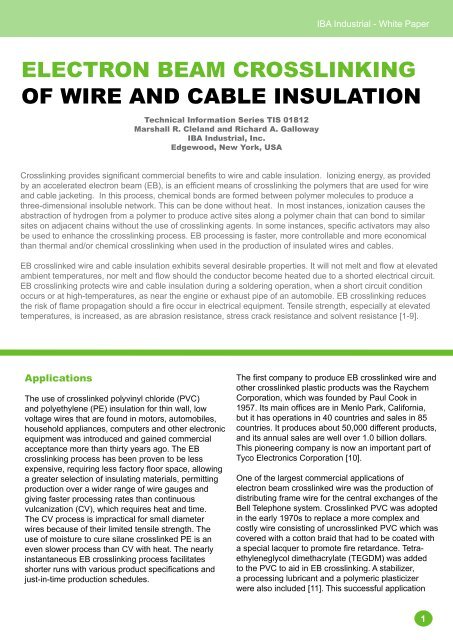
<strong>IBA</strong> <strong>Industrial</strong> - White PaperElectron Beam Crosslinking<strong>of</strong> Wire <strong>and</strong> Cable InsulationTechnical Information Series TIS 01812Marshall R. Clel<strong>and</strong> <strong>and</strong> Richard A. Galloway<strong>IBA</strong> <strong>Industrial</strong>, Inc.Edgewood, New York, USACrosslinking provides significant commercial benefits to wire <strong>and</strong> cable insulation. Ionizing energy, as providedby an accelerated electron beam (EB), is an efficient means <strong>of</strong> <strong>crosslinking</strong> the polymers that are used for wire<strong>and</strong> cable jacketing. In this process, chemical bonds are formed between polymer molecules to produce athree-dimensional insoluble network. This can be done without heat. In most instances, ionization causes theabstraction <strong>of</strong> hydrogen from a polymer to produce active sites along a polymer chain that can bond to similarsites on adjacent chains without the use <strong>of</strong> <strong>crosslinking</strong> agents. In some instances, specific activators may alsobe used to enhance the <strong>crosslinking</strong> process. EB processing is faster, more controllable <strong>and</strong> more economicalthan thermal <strong>and</strong>/or chemical <strong>crosslinking</strong> when used in the production <strong>of</strong> insulated wires <strong>and</strong> cables.EB crosslinked wire <strong>and</strong> cable insulation exhibits several desirable properties. It will not melt <strong>and</strong> flow at elevatedambient temperatures, nor melt <strong>and</strong> flow should the conductor become heated due to a shorted electrical circuit.EB <strong>crosslinking</strong> protects wire <strong>and</strong> cable insulation during a soldering operation, when a short circuit conditionoccurs or at high-temperatures, as near the engine or exhaust pipe <strong>of</strong> an automobile. EB <strong>crosslinking</strong> reducesthe risk <strong>of</strong> flame propagation should a fire occur in electrical equipment. Tensile strength, especially at elevatedtemperatures, is increased, as are abrasion resistance, stress crack resistance <strong>and</strong> solvent resistance [1-9].ApplicationsThe use <strong>of</strong> crosslinked polyvinyl chloride (PVC)<strong>and</strong> polyethylene (PE) insulation for thin wall, lowvoltage wires that are found in motors, automobiles,household appliances, computers <strong>and</strong> other electronicequipment was introduced <strong>and</strong> gained commercialacceptance more than thirty years ago. The EB<strong>crosslinking</strong> process has been proven to be lessexpensive, requiring less factory floor space, allowinga greater selection <strong>of</strong> insulating materials, permittingproduction over a wider range <strong>of</strong> wire gauges <strong>and</strong>giving faster processing rates than continuousvulcanization (CV), which requires heat <strong>and</strong> time.The CV process is impractical for small diameterwires because <strong>of</strong> their limited tensile strength. Theuse <strong>of</strong> moisture to cure silane crosslinked PE is aneven slower process than CV with heat. The nearlyinstantaneous EB <strong>crosslinking</strong> process facilitatesshorter runs with various product specifications <strong>and</strong>just-in-time production schedules.The first company to produce EB crosslinked wire <strong>and</strong>other crosslinked plastic products was the RaychemCorporation, which was founded by Paul Cook in1957. Its main <strong>of</strong>fices are in Menlo Park, California,but it has operations in 40 countries <strong>and</strong> sales in 85countries. It produces about 50,000 different products,<strong>and</strong> its annual sales are well over 1.0 billion dollars.This pioneering company is now an important part <strong>of</strong>Tyco Electronics Corporation [10].One <strong>of</strong> the largest commercial applications <strong>of</strong>electron beam crosslinked wire was the production <strong>of</strong>distributing frame wire for the central exchanges <strong>of</strong> theBell Telephone system. Crosslinked PVC was adoptedin the early 1970s to replace a more complex <strong>and</strong>costly wire consisting <strong>of</strong> uncrosslinked PVC which wascovered with a cotton braid that had to be coated witha special lacquer to promote fire retardance. Tetraethyleneglycoldimethacrylate (TEGDM) was addedto the PVC to aid in EB <strong>crosslinking</strong>. A stabilizer,a processing lubricant <strong>and</strong> a polymeric plasticizerwere also included [11]. This successful application1
<strong>IBA</strong> <strong>Industrial</strong> - White Papermotivated other organizations to develop wire <strong>and</strong>cable products using crosslinked PVC insulation [12-16]. Crosslinked PE <strong>and</strong> other ethylene copolymerswere also being developed at that time for highperformancewires <strong>and</strong> cables [17, 18].The Union Carbide Corporation (now part <strong>of</strong> DowChemical) developed an EB crosslinkable low smoke,low toxicity, flame retardant, non-halogen containing,cable jacketing compound that consists mainly <strong>of</strong>ethylene vinylacetate (EVA) <strong>and</strong> aluminum trihydrate(ATH). Similar EB crosslinked cables were specified bythe New York City Transit Authority for their buses <strong>and</strong>subway trains during the 1980s [9].Following a tragic fire aboard the aircraft carrier USSForrestall in 1967, the United States Navy realizedthat toxic fumes <strong>and</strong> dense smoke from burning PVCjacketed cables created a dangerous firefightingenvironment within the confines <strong>of</strong> a ship [19]. Inresponse to this, the US Navy developed a newspecification for a family <strong>of</strong> low smoke, low toxicityshipboard cables. The conductors were insulated withpolyolefins <strong>and</strong> jacketed with polyvinylidene fluoride(PVDF-Kynar) [9]. Both <strong>of</strong> these materials werecrosslinked with EB processing.EB crosslinked ethylene tetrafluoroethylene (ETFE-Tefzel) wire is also used in aircraft airframes. Thisinsulation is thinner <strong>and</strong> lighter than the materialsused for comparable wires. It can be used attemperatures up to 200 degrees Celcius <strong>and</strong> willperform temperatures as low as -65 °C [9]. In general,fluoropolymers are superior to the polyolefins, such aspolyethylene, for very high temperature applications[20-24].Another application <strong>of</strong> EB <strong>crosslinking</strong> is theproduction <strong>of</strong> anti-lock brake cables for automobiles.These cables must be flexible <strong>and</strong> resistant toabrasion from s<strong>and</strong> <strong>and</strong> gravel that are thrown upfrom the road. Resistance to salt, oil <strong>and</strong> gasoline isalso important. EB <strong>crosslinking</strong> is also used in theproduction <strong>of</strong> welding cables wherein EB crosslinksa rubber jacketing. In many areas, EB processing isTHE alternative to CV curing, as in this case. Theadvantage <strong>of</strong> EB curing is a higher production throughputrate <strong>and</strong> lower energy consumption than alternativecuring systems [9].Crosslinkable FormulationsPolyethylene (PE) is the most common polymerused for EB crosslinkable insulation. PE has lowcost, has a favorable response to EB processing<strong>and</strong> minimal toxicity when exposed to a fire. Blends<strong>of</strong> PE <strong>and</strong> ethylene-propylene copolymers (EPM) orethylene-propylene-diene (EPDM) elastomers areused if greater flexibility is needed. Flame retardantcompositions <strong>of</strong> PE/EPM or PE/EPDM are replacingpolyvinyl chloride (PVC) because <strong>of</strong> concerns overthe release <strong>of</strong> toxic chlorinated byproducts when PVCcompounds are exposed to a fire. PE, EPM <strong>and</strong> EPDMcan be made flame retardant by adding aluminumhydrates or other compounds to the formulation.Hydrates absorb energy <strong>and</strong> release water vaporwhen decomposed in a flame <strong>and</strong> thereby retard itspropagation.A typical flame retardant EB crosslinkable formulationis given below in Table 1. PE/EPM or PE/EPDM areused as the polymer base. This combination providesflexibility while not lowering dielectric properties<strong>and</strong> not increasing moisture permeability as wouldethylene copolymers, such as ethylene vinyl acetate(EVA) <strong>and</strong> ethylene acrylate copolymers, such asethylene ethylacrylate (EEA). In this illustrativeformulation, Hydral 710 is aluminum trihydrate(Al(OH)3), a compound that releases water whenexposed to combustion conditions. Zinc oxide (ZnO)is commonly used to enhance the aging properties<strong>of</strong> the material. A process aid, such as mineral oil,facilitates compound extrusion around the conductor.Silane A-172 is a wetting agent used to enhance theinteraction between the polymer <strong>and</strong> the Hydral 710.The antioxidant also reduces aging effects. Trimethylolpropane triacrylate (TMPTA) <strong>and</strong> tri-allyl cyanurate(TAC) are multi-functional monomers that enhance the<strong>crosslinking</strong> response <strong>and</strong> thus reduce the amount <strong>of</strong>dose needed to crosslink the wire or cable jacketing.This effect increases the processing speed. One orthe other <strong>of</strong> these agents can be used. This type <strong>of</strong>insulation can tolerate temperatures as high as 150 °C[7,25-30]. The weight fraction <strong>of</strong> Hydral 710 is 250/373= 0.67 <strong>and</strong> the calculated density <strong>of</strong> the insulation is1.61 g/cu cm. The density <strong>and</strong> atomic composition<strong>of</strong> this type <strong>of</strong> flame retardant insulation should betaken into account when determining the maximumEB penetration. (See the section below on PhysicalAspects, etc.)2
<strong>IBA</strong> <strong>Industrial</strong> - White PaperTable 1.Typical Flame Retardant Wire <strong>and</strong> Cable FormulationComponentParts by WeightPE-EPDM 100Hydral 710 250Zinc Oxide 5Process Aid 10Silane A-172 2Antioxidant 1TMPTA or TAC 5Processing MethodsSmall diameter wires or cables are usually EBcrosslinked by passing them many times througha wide, scanning beam. This method has severalbenefits. (1) A narrow, high-current electron beammust be scanned to increase its width <strong>and</strong> reducethe average current density to avoid overheating thethin metallic beam window <strong>of</strong> the accelerator; (2) Thescanning beam will be much wider than the wire orcable diameter, so that such products can pass throughthe beam many times to intercept most <strong>of</strong> the beamcurrent; (3) Multiple passes also avoid the possibility<strong>of</strong> overheating the insulated wire or cable by allowingsome <strong>of</strong> the heat from EB processing to dissipatebetween passes.Small wires can be EB processed while passing back<strong>and</strong> forth through the beam by using a wire h<strong>and</strong>lingfixture that consists <strong>of</strong> two rows <strong>of</strong> sheaves or two soliddrums displaced on opposite sides <strong>of</strong> the scanningbeam, as shown in Figure 1.Figure 1.A figure-eight multiple sheavefixture for electron beamprocessing <strong>of</strong> small size insulatedwire <strong>and</strong> plastic tubing.This arrangement is usually called the figure-eightmethod <strong>of</strong> under beam exposure. Larger wires <strong>and</strong>cables require a larger bending radius <strong>and</strong> can beprocessed with a four-drum fixture, as shown in Figure2.Figure 2.A four-drumfixture for electronbeam processing<strong>of</strong> medium sizeinsulated wire,cable <strong>and</strong> plastictubing.This is a modification <strong>of</strong> the simpler two-drum race trackmethod, which has the disadvantage when processingthicker wires <strong>and</strong> cables with larger drums in thatthe forward pass is closer to the beam window <strong>and</strong>receives a higher dose than the more distant reversepass. In addition to using larger outer drums for thickerwires <strong>and</strong> cables, the two inner drums <strong>of</strong> the four-drumfixture bring the reverse pass closer to the forward passso that the doses on opposite sides <strong>of</strong> the products arenearly the same. This method also keeps the forward<strong>and</strong> reverse passes perpendicular to the plane <strong>of</strong> thescanning electron beam so that the beam strikes thewires <strong>and</strong> cables at right angles to their direction <strong>of</strong>motion, thereby providing the greatest penetration intothe insulating material [30-32].The EB energy <strong>and</strong> consequently the electron rangeshould be at least sufficient to penetrate the radialthickness <strong>of</strong> the insulation <strong>and</strong> preferably more thanthis. Some <strong>of</strong> the beam will strike near the sides <strong>of</strong> thewire or cable where the chordal thickness is greaterthan the radial thickness. The electrons need notpenetrate the full chordal thickness since the wires willbe treated from opposite sides <strong>and</strong> small wires will twistslightly between successive passes on the under-beamh<strong>and</strong>ling system when passing through the beam. Also,the divergence <strong>of</strong> the scanning beam causes the sides<strong>of</strong> the wire or cable to be treated as the wire progressesfrom one end to the other <strong>of</strong> the multiple pass underbeamfixture [32].The outer sheaths on very large cables can be treatedby rotating the cables as they pass through theelectron beam along the scanning direction. With thismethod, both the pay-<strong>of</strong>f <strong>and</strong> take-up reels are rotatedoutside <strong>of</strong> the shielded treatment room. The electronenergy needs to be just enough to penetrate the radialthickness <strong>of</strong> the sheath. In this way, a nearly uniformdose distribution around the cable will result. Largecables may have to be cooled inside <strong>and</strong> outside <strong>of</strong> thetreatment room when a relatively high dose is deliveredin a single pass through the beam [33]. However,proper formulation <strong>of</strong> the cable jacketing can reduce thedose needed to impart <strong>crosslinking</strong> <strong>and</strong> thereby reducethe temperature rise.3
<strong>IBA</strong> <strong>Industrial</strong> - White PaperPhysical Aspects <strong>of</strong> Electron BeamProcessingElectron Energy RequirementThe amount <strong>of</strong> <strong>crosslinking</strong> increases with the dose,which is defined as the absorption <strong>of</strong> energy per unitmass. The common unit <strong>of</strong> dose for electron beamprocessing is the kilogray (kGy) or the absorption <strong>of</strong>one joule (watt-second) per gram <strong>of</strong> material. Polymer<strong>crosslinking</strong> usually requires doses in the range <strong>of</strong> 50to 150 kGy, depending on the chemical composition <strong>of</strong>the material.The dose within the material is usually not uniform.With electron energies above 500 kiloelectron volts(keV), the dose tends to increase with depth in thematerial to about half <strong>of</strong> the maximum electron range<strong>and</strong> then decrease to nearly zero at a greater depthwhere the electrons have dissipated most <strong>of</strong> theirkinetic energy. A useful quantity is the depth where theexit dose has diminished to 50 percent <strong>of</strong> the entrancedose. The electron energy should be enough to makethis quantity, usually named R(50e), equal to or greaterthan the thickness <strong>of</strong> the insulation. Values <strong>of</strong> R(opt),the depth where the exit dose equals the entrancedose, R(50), the depth where the exit dose equals 50percent <strong>of</strong> the maximum dose, <strong>and</strong> R(50e) are given inTables 2A <strong>and</strong> 2B for a wide range <strong>of</strong> electron energiesin flat materials, assuming the material compositionlisted in Table 1 above [34-36].Table 2A.Electron Ranges in Flame Retardant Polyethylene InsulationThe normalized ranges (thickness x density in g/sqcm) can be obtained by multiplying the ranges in cm,as given above, by the volume density <strong>of</strong> the flameretardant insulation, which has been calculated tobe 1.614 g/cu cm. Materials with different volumedensities tend to have similar normalized ranges,which can also be called areal or area densities.The areal density <strong>of</strong> a flat sheet can be measured bydividing its weight by its area. (Thickness x density =weight / area in g/sq cm). The areal density is a usefulquantity for comparing electron ranges in materialswith different compositions <strong>and</strong> volume densities [34-36].Table 2B.Electron Ranges in Flame Retardant Polyethylene InsulationIn addition to specifying the average dose needed tocrosslink the insulation, knowing the absorbed dosedistribution within the wire or cable insulation canprovide more assurance that the electron energy issufficient. The absorbed dose distribution depends onthe thickness, density <strong>and</strong> atomic composition <strong>of</strong> theinsulation as well as the diameter <strong>and</strong> composition<strong>of</strong> the metallic conductor. Because <strong>of</strong> the cylindricalgeometry <strong>and</strong> the shielding <strong>and</strong> backscattering effects<strong>of</strong> the conductor, accurate calculations <strong>of</strong> the dosedistribution are not simple, but they can be done withsuitable Monte Carlo probability codes. Several codesare available, but most <strong>of</strong> them are not very userfriendly[37, 38]. <strong>IBA</strong> <strong>Industrial</strong>, Inc. can provide adviceregarding these types <strong>of</strong> calculations [35].Temperature RiseThe thermal capacity <strong>of</strong> polymeric insulating materialis typically about half that <strong>of</strong> water, e.g. about 2 joulesper gram per degree Celcius. With this value, a dose<strong>of</strong> 100 kGy absorbed quickly in a single pass <strong>of</strong> thewire through the electron beam would cause thetemperature <strong>of</strong> the insulation to rise about 50 degreesCelcius. However, with a multiple-pass underbeamfixture which could have more than 100 passes, thedose per pass would be less than 1 kGy <strong>and</strong> thetemperature rise per pass would be less than halfa degree Celcius. The multiple-pass method allowsmuch <strong>of</strong> this heat to dissipate between passes.Processing RateThe results <strong>of</strong> Monte Carlo calculations <strong>of</strong> electronenergy depositions can also be used to estimate theline speed <strong>of</strong> an electron beam treatment process.The absorbed dose is proportional to the number<strong>of</strong> energetic electrons injected per unit area <strong>of</strong> theprocessed material, while the beam current is ameasure <strong>of</strong> the number <strong>of</strong> electrons emitted per unittime. Therefore, the processing rate or line speed <strong>of</strong>the wire or cable within the electron beam increaseswith the beam current <strong>and</strong> the number <strong>of</strong> passes<strong>and</strong> decreases with increasing beam width <strong>and</strong> doseaccording to the following equation:S = 6.0 D(e) I N / (W D)where S is the line speed in meters per minute <strong>and</strong>D(e) is the energy deposition per electron in MeV perunit areal density (thickness times volume density).This quantity can be calculated with a suitableMonte Carlo code. I is the electron beam current inmilliamperes, N is the number <strong>of</strong> passes through thebeam, W is the width <strong>of</strong> the scanning beam in meters<strong>and</strong> D is the total dose in kGy [34-36].4
<strong>IBA</strong> <strong>Industrial</strong> - White PaperValues <strong>of</strong> the energy deposition per electron D(e) for awide range <strong>of</strong> incident electron energies at the entrance<strong>of</strong> flat materials are given in Table 3, assuming thematerial composition listed in Table 1 above.Table 3.Electron Energy Deposition in Flame Retardant PE InsulationFigure 4.The interior <strong>of</strong> a Minitron TM steel<strong>and</strong> lead shielded enclosureshowing the vacuum pumps,beam scanning magnet, scanhorn, figure-eight multiple passfixture for small wire <strong>and</strong> tubing,<strong>and</strong> the water-cooled beam stop.For example, in flame retardant polyethylene, the value<strong>of</strong> D(e) is about 3.0 MeV per unit areal density (in gramsper square centimeter) for an electron energy <strong>of</strong> 800keV. Assuming that the beam current is 65 mA, thenumber <strong>of</strong> passes is 140, the scan width is 0.91 meters(36 inches) <strong>and</strong> the total dose is 150 kGy on the side<strong>of</strong> the wire facing the beam, then the line speed will beabout 1200 meters per minute.Figure 5 & 6.An Easy-e-Beam TM 800 keVself-shielded system forelectron beam processing <strong>of</strong>medium size insulated wire,cable <strong>and</strong> plastic tubing.Electron AcceleratorsElectron beam <strong>crosslinking</strong> <strong>of</strong> wire insulation <strong>and</strong>cable jackets is usually done with electron energiesin the range from 500 keV to 1.5 MeV, although somefacilities use higher energies up to 3 MeV. The energyis determined by the thickness, density <strong>and</strong> atomiccomposition <strong>of</strong> the insulation <strong>and</strong> the diameter <strong>of</strong> theconductor. The electron beam current is usually in therange <strong>of</strong> 25 to 100 mA. The beam current requirementis determined by the absorbed dose <strong>and</strong> the line speed.These relationships have been described briefly in theprevious sections.Facilities with electron energies less than 1.0 MeV canbe shielded with steel panels or a combination <strong>of</strong> steel<strong>and</strong> lead panels to protect operating personnel fromthe X-rays generated by the electron beam. Facilitieswith energies greater than 1.0 MeV are usually shieldedwith thick concrete walls, which are less expensive thanequivalent steel <strong>and</strong> lead panels for the higher energies.Photographs <strong>of</strong> a Minitron TM 500 keV self-shieldedsystem are shown in Figures 3 <strong>and</strong> 4. Drawings <strong>of</strong>an Easy-e-Beam TM 800 keV self-shielded system areshown in Figures 5 <strong>and</strong> 6. Drawings <strong>of</strong> Dynamitron ®1.5 MeV <strong>and</strong> 3.0 MeV concrete shielded systems areshown in Figures 7 <strong>and</strong> 8. All <strong>of</strong> these systems aresuitable for electron beam <strong>crosslinking</strong> <strong>of</strong> wires <strong>and</strong>cables.Figure 3.A Minitron TM 500 keV selfshieldedsystem for electronbeam processing <strong>of</strong> smallsize insulated wire <strong>and</strong> plastictubing.Summation<strong>IBA</strong> <strong>Industrial</strong>, Inc. (formerly known as RadiationDynamics, Inc.) has made many industrial electronaccelerators, called Dynamitrons ® , which are usedto crosslink wire <strong>and</strong> cable insulation <strong>and</strong> for otherapplications as well. This equipment has been provento be reliable <strong>and</strong> long lasting. Some Dynamitrons ®have been in use for more than 40 years. New modelswith the latest automatic control systems are now beingproduced to meet the present requirements for theseapplicationswww.iba-cables.comFigure 7. A Dynamitron® 1.5MeV concrete shielded systemfor electron beam processing<strong>of</strong> medium <strong>and</strong> large sizeinsulated wire, cable <strong>and</strong> plastictubing.Figure 8. A Dynamitron® 3.0MeV concrete shielded systemfor electron beam processing<strong>of</strong> medium <strong>and</strong> large sizeinsulated wire, cable <strong>and</strong> plastictubing.5
<strong>IBA</strong> <strong>Industrial</strong> - White PaperReferences[1] A. Charlesby, Atomic Radiation <strong>and</strong> Polymers, Pergamon Press, London, UK (1960).[2] A. Chapiro, Radiation Chemistry <strong>of</strong> Polymeric Systems, Interscience Publishers, John Wiley & Sons, Inc., London, UK (1962).[3] J. W. T. Spinks <strong>and</strong> R. J. Woods, An Introduction to Radiation Chemistry, John Wiley & Sons, Inc., New York, USA (1964).[4] J. W. T. Spinks <strong>and</strong> R. J. Woods, An Introduction to Radiation Chemistry, Third Edition, Wiley Interscience, New York, USA (1990).[5] R. J. Woods <strong>and</strong> A. K. Pikaev, Applied Radiation Chemistry: Radiation Processing, John Wiley & Sons, Inc., New York, USA (1994).[6] K. Dawes <strong>and</strong> L. C. Glover, Effects <strong>of</strong> Electron Beam <strong>and</strong> γ-Irradiation on Polymeric Materials, Chapter 41 in Physical Properties <strong>of</strong> PolymersH<strong>and</strong>book, James E. Mark, ed., AIP Press, American Institute <strong>of</strong> Physics, Woodbury, New York (1996) 557-576.[7] J. G. Drobny, Radiation Technology for Polymers, CRC Press, Boca Raton, Florida, USA (2003).[8] A. J. Berejka, <strong>Industrial</strong> Radiation Processing <strong>of</strong> Polymers Status <strong>and</strong> Prospects – August 2005, International Atomic Energy Agency, Vienna,Austria.[9] A. Zamore, J. Hackett <strong>and</strong> S. E. Wald, Successful Applications <strong>of</strong> Electron Beam Processing in Wire <strong>and</strong> Cable Manufacturing, TechnicalInformation Series TIS 01416, <strong>IBA</strong> <strong>Industrial</strong>, Inc., 151 Heartl<strong>and</strong> Blvd., Edgewood, New York 11717, USA (1993).[10] Anon, Raychem Corporation, http://www.answers.com/topic/raychem-corporation.[11] L. D. Loan, Applications+ <strong>of</strong> Radiation Processing in the Wire <strong>and</strong> Cable Field, Radiation Physics <strong>and</strong> Chemistry, Vol. 9, Nos. 1-3 (1977) 253-259.[12] E. Saito, Application <strong>of</strong> Irradiation Process for the Production <strong>of</strong> Thin Wall Wires, Radiation Physics <strong>and</strong> Chemistry, Vol. 9, Nos. 4-6 (1977)675-684.[13] P. G. Goavec, Plastic Materials <strong>and</strong> Acome’s Use <strong>of</strong> High Energy Electron Processing in France, Radiation Physics <strong>and</strong> Chemistry, Vol. 14,Nos. 1-2 (1979) 61-67.[14] E. W. Bennett, Jr., Applications <strong>of</strong> Irradiation to <strong>Industrial</strong> Wires <strong>and</strong> Cables, Radiation Physics <strong>and</strong> Chemistry, Vol. 14, Nos. 3-6 (1979) 947-951.[15] R. G. Bruce Mitchell, Crosslinkable PVC Compounds for Wire <strong>and</strong> Cable Insulation, Radiation Physics <strong>and</strong> Chemistry, Vol. 14, Nos. 3-6 (1979)937-940.[16] I. Uda, Irradiated Wires for Internal Wiring, Radiation Physics <strong>and</strong> Chemistry, Vol. 14, Nos. 3-6 (1979) 941-946.[17] A. Barlow, J. Biggs <strong>and</strong> M. Maringer, Radiation Processing <strong>of</strong> Polyolefins <strong>and</strong> Compounds, Radiation Physics <strong>and</strong> Chemistry, Vol. 9, Nos. 4-6(1977) 685-699.[18] N. M. Burns, The Radiation Crosslinking <strong>of</strong> Ethylene Copolymers, Radiation Physics <strong>and</strong> Chemistry, Vol. 14, Nos. 3-6 (1979) 797-808.[19] Anon, 1967 USS Forrestal fire, http://en.wikipedia.org/wiki/1967_USS_Forrestall_fire.[20] R. Timmerman, Crosslinking <strong>of</strong> Polyvinylidene Fluoride <strong>and</strong> Wire Coated with the Crosslinked Resin, U. S. Patent No. 3,142,629, July 28(1964).[21] B. J. Lyons, Radiation Crosslinking <strong>of</strong> Fluoropolymers – A Review, Radiation Physics <strong>and</strong> Chemistry, Vol. 45, No. 2 (1995) 159-174.[22] H. P. Fisher, The Effect <strong>of</strong> Ionizing Radiation on Fluoropolymer Coatings, http://www.gloveboxsociety.org/files/tech_library/tech-14.pdf.[23] J. G. Drobny, Radiation Processing <strong>of</strong> Fluoropolymers, http://www.radtecheurope.com/files_content/november%202004%20papers/drobnypapernovember2004.pdf.[24] J. G. Drobny, Technology <strong>of</strong> Fluoropolymers, Second Edition, CRC Press (2008).[25] L. Spenadel, Radiation Crosslinking <strong>of</strong> Polymer Blends, Radiation Physics <strong>and</strong> Chemistry, Vol. 14, Nos. 3-6 (1979) 683-697.[26] L. Spenadel, Electron Beam Crosslinking <strong>of</strong> Ethylene Propylene Electrical Compounds, Journal <strong>of</strong> <strong>Industrial</strong> Irradiation Technology, Vol. 3, No.1 (1985) 7-39.[27] Anon, Vistalon Ethylene-Propylene Elastomers, Radiation Cured Electrical Materials, Product Report 82 ET-B 348, Essochem Europe, Inc.(1982) 16-19.[28] Anon, Flame Retardance in Vamac Ethylene Acrylic Elastomers, Doc. Ref. VAM020925_2, v.1, E.I. du Pont de Nemours <strong>and</strong> Company,Inc.,September (2002).[29] J. P. Christiano, Extrusion <strong>of</strong> Zero Halogen Flame Retardant Compounds for Wire <strong>and</strong> Cable Applications, International PolyolefinsConference, sponsored by the Society <strong>of</strong> Plastics Engineers, held in Houston, Texas, on February 22 – February 25, 2009.[30] A. J. Berejka, M. R. Clel<strong>and</strong>, et al, <strong>Industrial</strong> Electron Beam Processing, International Atomic Energy Agency, <strong>Industrial</strong> Irradiation Associates(2009).[31] R. Bradley, Chapter 9, Application: Wire <strong>and</strong> Cable, Radiation Technology H<strong>and</strong>book, Marcel Dekker, Inc., New York 10016, USA (1984) 211-240.[32] J. H. Bly, Chapter VI, Wire, Flexible Cable <strong>and</strong> Tubing, Electron Beam Processing, International Information Associates, Yardley, Pennsylvania19067, USA (1988) 55-73.[33] H. R. Studer, Irradiation <strong>of</strong> Insulation <strong>and</strong> Sheath for Large Wire <strong>and</strong> Cable, Radiation Physics <strong>and</strong> Chemistry, Vol. 14, Nos. 3-6 (1979) 809-819.[34] M. Clel<strong>and</strong>, R. Galloway, F. Genin <strong>and</strong> M. Lindholm, The Use <strong>of</strong> Dose <strong>and</strong> Charge Distributions in Electron Beam Processing, RadiationPhysics <strong>and</strong> Chemistry, Vol. 63, Nos. 3-6 (2002) 729-733.[35] M. R. Clel<strong>and</strong> <strong>and</strong> R. A. Galloway, Accelerator Requirements for Electron Beam Crosslinking <strong>of</strong> Wire <strong>and</strong> Cable Insulation, TechnicalInformation Series, TIS 01813 (2009), <strong>IBA</strong> <strong>Industrial</strong>, Inc., Edgewood, NY.[36] Anon, ISO/ASTM 51649:2005, Practice for Dosimetry in an Electron Beam Facility for Radiation Processing at Energies Between 300 keV <strong>and</strong>6