download - Kckong.info
download - Kckong.info
download - Kckong.info

You also want an ePaper? Increase the reach of your titles
YUMPU automatically turns print PDFs into web optimized ePapers that Google loves.
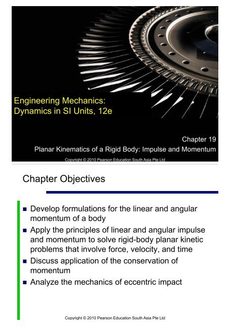
Engineering Mechanics:<br />
Dynamics in SI Units, 12e<br />
Copyright © 2010 Pearson Education South Asia Pte Ltd<br />
Chapter 19<br />
Planar Kinematics of a Rigid Body: Impulse and Momentum<br />
Chapter Objectives<br />
Develop formulations for the linear and angular<br />
momentum of a body<br />
Apply the principles of linear and angular impulse<br />
and momentum to solve rigid-body planar kinetic<br />
problems that involve force, velocity, and time<br />
Discuss application of the conservation of<br />
momentum<br />
Analyze the mechanics of eccentric impact<br />
Copyright © 2010 Pearson Education South Asia Pte Ltd
Chapter Outline<br />
1. Linear and Angular Momentum<br />
2. Principle of Impulse and Momentum<br />
3. Conservation of Momentum<br />
4. Eccentric Impact*<br />
Copyright © 2010 Pearson Education South Asia Pte Ltd<br />
19.1 Linear and Angular Momentum<br />
We will assume the body is symmetric with<br />
respect to an inertial x-y reference plane<br />
Linear Momentum<br />
The linear momentum of a rigid body is<br />
determined by L = m i v i<br />
m i v i = mv G ,<br />
momentum is a vector quantity having a<br />
magnitude mv G , and a direction defined by v G<br />
Copyright © 2010 Pearson Education South Asia Pte Ltd
19.1 Linear and Angular Momentum<br />
Angular Momentum<br />
Consider the body subjected to general planar<br />
motion<br />
Arbitrary point P has a velocity v P , and body has<br />
an angular velocity<br />
The velocity of the ith particle is<br />
The angular momentum is<br />
Copyright © 2010 Pearson Education South Asia Pte Ltd<br />
19.1 Linear and Angular Momentum<br />
Angular Momentum<br />
Using Cartesian vectors,<br />
Letting m i dm and integrating over the entire<br />
mass m of the body,<br />
Copyright © 2010 Pearson Education South Asia Pte Ltd
19.1 Linear and Angular Momentum<br />
Angular Momentum<br />
inertia computed about the z axis, I P = r 2 dm<br />
Equation can be reduced to a<br />
simpler form if point P coincides<br />
with the mass center G for the<br />
body where<br />
Copyright © 2010 Pearson Education South Asia Pte Ltd<br />
19.1 Linear and Angular Momentum<br />
Angular Momentum<br />
Thus<br />
It states that the angular momentum of the body<br />
computed about G is equal to the product of<br />
moment of inertia of the body about an axis<br />
velocity.<br />
Can also written as<br />
Copyright © 2010 Pearson Education South Asia Pte Ltd
19.1 Linear and Angular Momentum<br />
Translation<br />
When a rigid body of mass m is subjected to<br />
rectilinear or curvilinear translation, its mass<br />
center has a velocity of v G = v and = 0<br />
The linear momentum and the angular<br />
momentum computed about G is<br />
Since d is the moment arm,<br />
H A = (d)(mv G )<br />
Copyright © 2010 Pearson Education South Asia Pte Ltd<br />
19.1 Linear and Angular Momentum<br />
Rotation About a Fixed Axis<br />
When a rigid body is rotating about a fixed axis<br />
passing through point O, the linear momentum<br />
and the angular momentum about G are<br />
Noting that L (or v G ) is always<br />
perpendicular to r G ,<br />
Copyright © 2010 Pearson Education South Asia Pte Ltd
19.1 Linear and Angular Momentum<br />
Rotation About a Fixed Axis<br />
Equation can be simplified by substituting<br />
v G = r G , and using parallel-axis theorem<br />
Hence,<br />
General Plane Motion<br />
When a rigid body is subjected<br />
to general plane motion,<br />
Copyright © 2010 Pearson Education South Asia Pte Ltd<br />
19.1 Linear and Angular Momentum<br />
General Plane Motion<br />
When angular momentum is computed about a<br />
point A located either on or off the body,<br />
Copyright © 2010 Pearson Education South Asia Pte Ltd
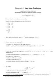
Example 19.1<br />
At a given instant the 5-kg slender bar has the<br />
motion as shown. Determine its angular momentum<br />
about point G and about the IC at this instant.<br />
Copyright © 2010 Pearson Education South Asia Pte Ltd<br />
Example 19.2<br />
Solution<br />
Bar<br />
The bar undergoes general plane motion, we have<br />
Thus,<br />
Copyright © 2010 Pearson Education South Asia Pte Ltd
Example 19.2<br />
Solution<br />
Bar<br />
Adding I G w and the moment of mv G about the IC<br />
yields<br />
Copyright © 2010 Pearson Education South Asia Pte Ltd<br />
19.2 Principle of Impulse and Momentum<br />
Principle of Linear Impulse and Momentum<br />
The equation of translational motion for a rigid<br />
body can be written as F = ma G = m (dv G /dt)<br />
Since the mass of the body is constant,<br />
Multiplying both sides by dt and integrating from t<br />
= t 1 , v G = (v G ) 1 to t = t 2 , v G = (v G ) 2 yields<br />
Copyright © 2010 Pearson Education South Asia Pte Ltd
19.2 Principle of Impulse and Momentum<br />
Principle of Linear Impulse and Momentum<br />
This equation is referred to as the principle of<br />
linear impulse and momentum.<br />
It states that the sum of all impulses created by<br />
the external force system which acts on the body<br />
during the time interval t 1 to t 2 equal to the<br />
change in the linear momentum of the body<br />
during the time interval.<br />
Copyright © 2010 Pearson Education South Asia Pte Ltd<br />
19.2 Principle of Impulse and Momentum<br />
Principle of Linear Impulse and Momentum<br />
+ =<br />
Copyright © 2010 Pearson Education South Asia Pte Ltd
19.2 Principle of Impulse and Momentum<br />
Principle of Angular Impulse and Momentum<br />
If the body has general plane motion we can<br />
write M G = I G = I G (d /dt)<br />
Since the moment of inertia is constant,<br />
Multiplying both sides by dt and integrating from t<br />
= t 1 , = 1 to t = t 2 , = 2 gives<br />
Copyright © 2010 Pearson Education South Asia Pte Ltd<br />
19.2 Principle of Impulse and Momentum<br />
Principle of Angular Impulse and Momentum<br />
In a similar manner, for rotation about a fixed<br />
axis passing through point O, M O = I O when<br />
integrated becomes<br />
Both equations are referred to as the principle of<br />
angular impulse and momentum.<br />
They state that the sum of the angular impulses<br />
acting on the body during the time interval t 1 to t 2<br />
momentum during this time interval.<br />
Copyright © 2010 Pearson Education South Asia Pte Ltd
19.2 Principle of Impulse and Momentum<br />
Principle of Angular Impulse and Momentum<br />
To summarize the preceding concepts,<br />
m(<br />
v<br />
m(<br />
v<br />
I<br />
G<br />
Gx<br />
Gy<br />
)<br />
)<br />
1<br />
1<br />
1<br />
t 2<br />
t1<br />
t 2<br />
t1<br />
t 2<br />
t1<br />
F<br />
F<br />
M<br />
x<br />
y<br />
G<br />
dt<br />
dt<br />
dt<br />
m(<br />
v<br />
m(<br />
v<br />
I<br />
G<br />
Gx<br />
Gy<br />
2<br />
)<br />
)<br />
2<br />
2<br />
Copyright © 2010 Pearson Education South Asia Pte Ltd<br />
19.2 Principle of Impulse and Momentum<br />
Principle of Angular Impulse and Momentum<br />
The resultant equations may be written in<br />
symbolic form as<br />
syst.<br />
linear<br />
syst.<br />
linear<br />
syst.<br />
linear<br />
momentum<br />
x1<br />
impulse<br />
x(1<br />
2)<br />
momentum<br />
x2<br />
syst.<br />
linear<br />
syst.<br />
linear<br />
syst.<br />
linear<br />
momentum<br />
y1<br />
impulse<br />
y(1<br />
2)<br />
momentum<br />
y2<br />
syst.<br />
angular<br />
syst.<br />
angular<br />
syst.<br />
angular<br />
momentum<br />
O1<br />
impulse<br />
O(1<br />
2)<br />
momentum<br />
O2<br />
Copyright © 2010 Pearson Education South Asia Pte Ltd
19.2 Principle of Impulse and Momentum<br />
Procedure for Analysis<br />
Free Body Diagram<br />
Establish x, y, z inertial frame of reference and<br />
draw the free-body diagram.<br />
Establish the direction and sense of the initial<br />
v G ,<br />
Assume that the sense of its components is in<br />
the direction of the positive inertial coordinates<br />
Compute the moment of inertia I G or I O<br />
Copyright © 2010 Pearson Education South Asia Pte Ltd<br />
19.2 Principle of Impulse and Momentum<br />
Procedure for Analysis<br />
Principle of Impulse and Momentum<br />
Apply the three scalar equations of impulse and<br />
momentum.<br />
The angular momentum of a rigid body rotating<br />
about a fixed axis is the moment of mv G plus I G<br />
about the axis.<br />
diagram will create an impulse.<br />
-body<br />
Copyright © 2010 Pearson Education South Asia Pte Ltd
19.2 Principle of Impulse and Momentum<br />
Procedure for Analysis<br />
Principle of Impulse and Momentum<br />
Forces that are functions of time must be integrated to<br />
obtain the impulse.<br />
Principle of angular impulse and momentum is used to<br />
eliminate unknown impulsive forces that are parallel or<br />
pass through a common axis.<br />
Kinematics<br />
If more than 3 equations are needed, we relate the<br />
velocity using kinematics.<br />
Kinematic (velocity) diagrams are helpful in obtaining the<br />
necessary relation.<br />
Copyright © 2010 Pearson Education South Asia Pte Ltd<br />
Example 19.2<br />
The 100-N disk is assumed to be uniform and is pin<br />
supported at its center. If it is acted upon by a<br />
constant couple moment of 6 N.m and a force of 50<br />
N which is applied to a cord wrapped around its<br />
periphery, determine the angular velocity of the disk<br />
two seconds after starting from rest. Also, what are<br />
the force components of reaction at the pin<br />
Copyright © 2010 Pearson Education South Asia Pte Ltd
Example 19.2<br />
Solution<br />
Free Body Diagrams<br />
The loading causes the disk to rotate clockwise.<br />
The moment of inertia of the disk about its fixed axis<br />
of rotation is<br />
Copyright © 2010 Pearson Education South Asia Pte Ltd<br />
Example 19.2<br />
Solution<br />
Principle of Impulse and Momentum<br />
We have<br />
I<br />
m(<br />
v<br />
A<br />
m(<br />
v<br />
1<br />
Ax<br />
Ay<br />
)<br />
)<br />
1<br />
1<br />
0<br />
(2)<br />
m(<br />
v<br />
0 Ay(2)<br />
100(2) 50(2) 0<br />
t<br />
t<br />
1<br />
2<br />
M<br />
t<br />
A<br />
t<br />
t<br />
1<br />
t<br />
1<br />
A<br />
2<br />
0 6(2) [50(2)](0.25) 0.31855<br />
2<br />
x<br />
dt<br />
F<br />
F<br />
y<br />
x<br />
dt<br />
dt<br />
I<br />
A<br />
0<br />
m(<br />
v<br />
2<br />
Ax<br />
Ay<br />
)<br />
)<br />
2<br />
2<br />
2<br />
Copyright © 2010 Pearson Education South Asia Pte Ltd
Example 19.2<br />
Solution<br />
Principle of Impulse and Momentum<br />
Solving,<br />
Copyright © 2010 Pearson Education South Asia Pte Ltd<br />
Example 19.4<br />
The block has a mass of 6 kg. It is attached to a cord<br />
which is attached to a cord which is wrapped around<br />
the periphery of a 20-kg disk that has a moment of<br />
inertia IA = 0.40 kg.m2. If the block is initially moving<br />
downward with a speed of 2 m/s, determine its<br />
speed in 3 s.<br />
Copyright © 2010 Pearson Education South Asia Pte Ltd
Example 19.4<br />
Solution<br />
Free Body Diagrams<br />
All the forces are constant since the weight of the<br />
block causes the motion.<br />
The downward motion of the block, v B , causes<br />
the disk to be clockwise.<br />
of<br />
Copyright © 2010 Pearson Education South Asia Pte Ltd<br />
Example 19.4<br />
Solution<br />
Principle of Impulse and Momentum<br />
We can eliminate A x and A y from the analysis by<br />
applying the angular impulse and momentum about<br />
point A.<br />
Disk<br />
Copyright © 2010 Pearson Education South Asia Pte Ltd
Example 19.4<br />
Solution<br />
Cylinder<br />
Kinematics<br />
Since = v B /r then 1 = 2/0.2 = 10 rad/s and 2 =<br />
(v B ) 2 /0.2 = 5(v B ) 2<br />
Substituting and solving the equations,<br />
Copyright © 2010 Pearson Education South Asia Pte Ltd<br />
19.3 Conservation of Momentum<br />
Conservation of Linear Momentum<br />
When the sum of all the linear impulses acting on<br />
the system of connected rigid is zero, the linear<br />
momentum of the system is conserved.<br />
This equation is the conservation of linear<br />
momentum.<br />
Copyright © 2010 Pearson Education South Asia Pte Ltd
19.3 Conservation of Momentum<br />
Conservation of Angular Momentum<br />
Angular momentum is conserved about the<br />
G when the sum of all<br />
the angular impulses is zero.<br />
Copyright © 2010 Pearson Education South Asia Pte Ltd<br />
19.3 Conservation of Momentum<br />
Procedure for Analysis<br />
Free-body Diagram<br />
Classify each of the applied forces as being<br />
-<br />
From FBD, the conservation of linear momentum<br />
applies when no external impulsive forces act on<br />
the body or system in that direction.<br />
The conservation of angular momentum applies<br />
at the mass center G when all external impulsive<br />
forces acting on the body or system create zero<br />
moment.<br />
Copyright © 2010 Pearson Education South Asia Pte Ltd
19.3 Conservation of Momentum<br />
Procedure for Analysis<br />
Conservation of Momentum<br />
Apply the conservation of linear or angular<br />
momentum in the appropriate directions.<br />
Kinematics<br />
If the motion appears to be complicated,<br />
kinematics (velocity) diagrams may be helpful in<br />
obtaining the necessary kinematics relations.<br />
Copyright © 2010 Pearson Education South Asia Pte Ltd<br />
Example 19.6<br />
The 10 kg wheel has a moment of inertia I G = 0.156<br />
kg.m2. Assuming that the wheel does not slip or<br />
rebound, determine the minimum velocity v G it must<br />
have to just roll over the obstruction at A.<br />
Copyright © 2010 Pearson Education South Asia Pte Ltd
Example 19.6<br />
Solution<br />
Impulse and Momentum Diagrams<br />
There is no slipping.<br />
We have the momentum of the wheel<br />
just before impact, the impulses given<br />
to the wheel during impact, and the<br />
momentum of the wheel just after<br />
impact.<br />
Copyright © 2010 Pearson Education South Asia Pte Ltd<br />
Example 19.6<br />
Solution<br />
Conservation of Angular Momentum<br />
Kinematics<br />
Since no slipping occurs, = v G /r = v G /0.2 = 5v G<br />
Substituting this into the above equation,<br />
(1)<br />
Copyright © 2010 Pearson Education South Asia Pte Ltd
Example 19.6<br />
Solution<br />
Conservation of Energy<br />
In order to roll over the obstruction, the wheel must<br />
pass position 3.<br />
From conservation of energy equation,<br />
Substituting 2 = 5(v G ) 2 into Eq. ,<br />
Copyright © 2010 Pearson Education South Asia Pte Ltd<br />
19.4 Eccentric Impact*<br />
Eccentric impact occurs when the line<br />
connecting the mass centers of the two bodies<br />
does not coincide with the line of impact.<br />
Occurs when one or both of the bodies are<br />
constrained to rotate about a fixed axis.<br />
A problem involving the impact of two bodies<br />
requires determining the two<br />
unknowns (v A ) 2 and (v B ) 2 ,<br />
assuming (v A ) 1 and (v B ) 1<br />
are known or to be determined.<br />
Copyright © 2010 Pearson Education South Asia Pte Ltd
19.4 Eccentric Impact*<br />
To solve this problem, 2 equations are needed.<br />
The 1 st equation is the conservation of angular<br />
momentum.<br />
The 2 nd equation is using the definition of the<br />
coefficient of restitution, e, which is the ratio of<br />
the restitution impulse to the deformation<br />
impulse.<br />
(+ )<br />
B<br />
A<br />
2<br />
1<br />
A<br />
B<br />
2<br />
1<br />
Copyright © 2010 Pearson Education South Asia Pte Ltd<br />
19.4 Eccentric Impact*<br />
Copyright © 2010 Pearson Education South Asia Pte Ltd
Example 19.8<br />
The 5-kg slender rod is suspended from the pin at A.<br />
If a 1-kg ball B is thrown at the rod and strikes its<br />
center with a horizontal velocity of 9 m/s, determine<br />
the angular velocity of the rod just after impact. The<br />
coefficient of restitution is e = 0.4<br />
Copyright © 2010 Pearson Education South Asia Pte Ltd<br />
Example 19.8<br />
Solution<br />
Conservation of Angular Momentum<br />
Angular momentum is conserved about point A since<br />
the impulsive force between the rod and the ball is<br />
internal.<br />
The weights of the ball and rod are non-impulsive.<br />
Copyright © 2010 Pearson Education South Asia Pte Ltd
Example 19.8<br />
Solution<br />
Conservation of Angular Momentum<br />
We have<br />
A<br />
1<br />
A<br />
2<br />
B<br />
B<br />
1<br />
B<br />
B<br />
2<br />
R<br />
G<br />
2<br />
G<br />
2<br />
B<br />
2<br />
G<br />
2<br />
2<br />
2<br />
Since (v G ) 2 = 0.5<br />
2 , then<br />
Copyright © 2010 Pearson Education South Asia Pte Ltd<br />
Example 19.8<br />
Solution<br />
Coefficient of Restitution<br />
We have<br />
Solving<br />
Copyright © 2010 Pearson Education South Asia Pte Ltd
![Digital Control Systems [MEE 4003] - Kckong.info](https://img.yumpu.com/40221932/1/184x260/digital-control-systems-mee-4003-kckonginfo.jpg?quality=85)
![Digital Control Systems [MEE 4003] - Kckong.info](https://img.yumpu.com/32606446/1/184x260/digital-control-systems-mee-4003-kckonginfo.jpg?quality=85)