5/2 Directional Control Valves Actuation: Electromagnetic ... - Auser
5/2 Directional Control Valves Actuation: Electromagnetic ... - Auser
5/2 Directional Control Valves Actuation: Electromagnetic ... - Auser

Create successful ePaper yourself
Turn your PDF publications into a flip-book with our unique Google optimized e-Paper software.
26360<br />
● For double-acting actuators<br />
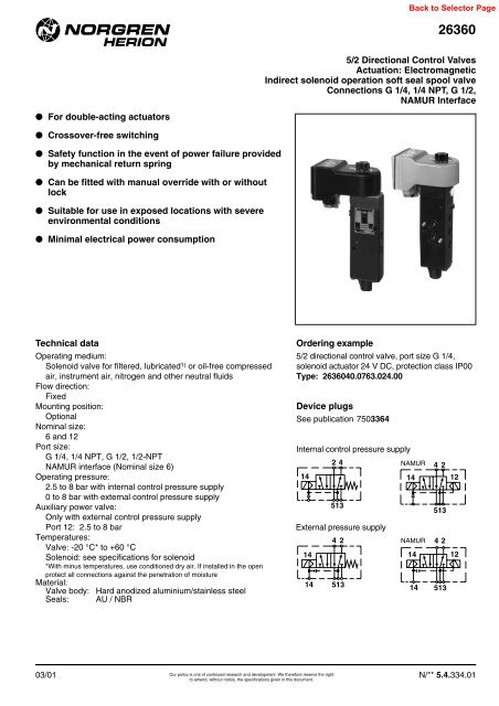
5/2 <strong>Directional</strong> <strong>Control</strong> <strong>Valves</strong><br />
<strong>Actuation</strong>: <strong>Electromagnetic</strong><br />
Indirect solenoid operation soft seal spool valve<br />
Connections G 1/4, 1/4 NPT, G 1/2,<br />
NAMUR Interface<br />
● Crossover-free switching<br />
● Safety function in the event of power failure provided<br />
by mechanical return spring<br />
● Can be fitted with manual override with or without<br />
lock<br />
● Suitable for use in exposed locations with severe<br />
environmental conditions<br />
● Minimal electrical power consumption<br />
Technical data<br />
Operating medium:<br />
Solenoid valve for filtered, lubricated 1) or oil-free compressed<br />
air, instrument air, nitrogen and other neutral fluids<br />
Flow direction:<br />
Fixed<br />
Mounting position:<br />
Optional<br />
Nominal size:<br />
6 and 12<br />
Port size:<br />
G 1/4, 1/4 NPT, G 1/2, 1/2-NPT<br />
NAMUR interface (Nominal size 6)<br />
Operating pressure:<br />
2.5 to 8 bar with internal control pressure supply<br />
0 to 8 bar with external control pressure supply<br />
Auxiliary power valve:<br />
Only with external control pressure supply<br />
Port 12: 2.5 to 8 bar<br />
Temperatures:<br />
Valve: -20 °C* to +60 °C<br />
Solenoid: see specifications for solenoid<br />
*With minus temperatures, use conditioned dry air. If installed in the open<br />
protect all connections against the penetration of moisture<br />
Material:<br />
Valve body: Hard anodized aluminium/stainless steel<br />
Seals: AU / NBR<br />
Ordering example<br />
5/2 directional control valve, port size G 1/4,<br />
solenoid actuator 24 V DC, protection class IP00<br />
Type: 2636040.0763.024.00<br />
Device plugs<br />
See publication 7503364<br />
Internal control pressure supply<br />
14<br />
24<br />
513<br />
External pressure supply<br />
14<br />
42<br />
14 513<br />
NAMUR<br />
42<br />
14 12<br />
NAMUR<br />
513<br />
4 2<br />
14 12<br />
14 513<br />
03/01<br />
Our policy is one of continued research and development. We therefore reserve the right<br />
N/** 5.4.334.01<br />
to amend, without notice, the specifications given in this document.
26360<br />
General information<br />
Symbol Type Pipe connections Nominal Operating pressure (bar) <strong>Control</strong> pressure supply (bar) Flow rate Weight Dimensional Special features<br />
1 + 3 2 + 3 size Min. Max. Internal External (l/min) (kg) drawing No.<br />
42 2636040.* G 1/4 G 1/4 6 2.5 8 ● – 900 0.7 M02<br />
2636042.* 1/4 NPT 1/4 NPT 6 2.5 8 ● – 900 0.7 M02<br />
14<br />
2636095.* 1/4 NPT 1/4 NPT 6 2.5 8 ● – 900 0.7 M02 Semi-automatic E 1.10<br />
2637040.* G 1/2 G 1/2 12 2.5 8 ● – 2200 1.3 M02<br />
513 2637049.* 1/2 NPT 1/2 NPT 12 2.5 8 ● – 2200 1.3 M02<br />
42 2636097.* G 1/4 G 1/4 6 0 8 – 2.5 bis 8 900 0.7 M02<br />
14<br />
2637097.* G 1/2 G 1/2 12 0 8 – 2.5 bis 8 2200 1.3 M02<br />
14 513<br />
42<br />
14 12<br />
2636240.* G 1/4 G 1/4 6 2.5 8 ● – 900 0.85 M04<br />
513<br />
4 2<br />
14 12<br />
2636297.* G 1/4 G 1/4 6 0 8 – 2.5 bis 8 900 0.85 M04<br />
14 513<br />
NAMUR flange<br />
Symbol Type Pipe connections Nominal Operating pressure (bar) <strong>Control</strong> pressure supply (bar) Flow rate Weight Dimensional Special features<br />
1 + 3 2 + 3 size Min. Max. Internal External (l/min) (kg) drawing No.<br />
24 2636044.* G 1/4 Flange 6 2.5 8 ● – 900 0.7 M01<br />
14<br />
2636094.* 1/4 NPT Flange 6 2.5 8 ● – 900 0.7 M01<br />
14<br />
513<br />
42<br />
2636099.* G 1/4 Flange 6 0 8 – 2.5 to 8 900 0.7 M01<br />
14 513<br />
42<br />
14 12<br />
2636244.* G 1/4 Flange 6 2.5 8 ● – 900 0.85 M03<br />
2636294.* 1/4 NPT Flange 6 2.5 8 ● – 900 0.85 M03<br />
513<br />
4 2<br />
14 12<br />
2636299.* G 1/4 Flange 6 0 8 – 2.5 to 8 900 0.85 M03<br />
14 513<br />
* When ordering please indicate solenoid, voltage and current type (frequency)..<br />
** 2 mounting screws M5 x 45 DIN 912 A2/A4 are included in the scope of delivery.<br />
Our policy is one of continued research and development. We therefore reserve the right<br />
N/** 5.4.334.02 to amend, without notice, the specifications given in this document.<br />
03/01
26360<br />
Solenoid parameters<br />
Type Power. consumption Rated current Rated voltage Protection class Temperature Weight Dimensional Circuit<br />
24 V DC 230 V AC 24 V DC 230 V AC tolerance Fluid max. Ambient drawing No. diagram<br />
(W) (VA) (mA) (mA) +(%) –(%) (°C) (°C) (kg) No.<br />
0763 1) 1.9 – 78 – 10 15 IP00 without connector +80 -25 to +60 0.3 M10 SB01<br />
IP65 with connector<br />
DIN 43650 form A<br />
0278 2) 3.2 – 135 – 10 15 SB04<br />
EEx m II T4 +70 -25 to +70 0.4 M09<br />
0279 2) – 3.5 – 15 10 15 SB07<br />
3900 3) 0.7 – 29 – 10 15 EEx me II T5/T6<br />
3910 3) 3.9 – 161 21 10 15 EEx me II T5/T6<br />
3911 3) – 4.9 – – 10 15 EEx me II T5/T6<br />
-20 to +80 (T5)<br />
-40 to +70 (T6)<br />
-20 to +80 (T5)<br />
-40 to +60 (T6)<br />
-20 to +80 (T5)<br />
-40 to +60 (T6)<br />
SB04<br />
0.85 M07 SB04<br />
SB07<br />
3720 4) 1.4 – 59 – 10 15 NEMA 4, 4X, 6, 6P, 7, 9 -20 to +60 0.4 M11 SB01<br />
stranded wire<br />
460 mm long<br />
Standard voltages 24 V DC, 230 V AC. Other voltages on request.<br />
1) Required device socket Type: 0570275 for DC, device socket with rectifier Type: 0663303 for AC or AC/DC<br />
2) Certificate of conformity KEMA No. Ex-93.C.8283 C<br />
3) Certificate of conformity PTB No. Ex-92.C.2175 C<br />
4) CSA-LR 57643-6, FM approved, for hazardous locations: Div. 1 and 2, Classes I, II and III<br />
Solenoid actuators for intrinsically-safe circuits, protection class EEx ia IIC T6** zone 1 and 2<br />
Type Nominal resist. Min. required Resistance Required voltage Ambient Max. Fluid- Weight Dimensional Circuit<br />
RV Coil switching current Rw 65 Coil* at terminal temperature temperature drawing No. diagram<br />
(Ω) (mA) (Ω) Rw 65 (°C) (°C) (kg) No.<br />
2030 124 43 150 6.4<br />
2031 159 38 193 7.3<br />
2032 198 34 240 8.2<br />
2033 248 30 3019.0<br />
2034 306 27 37110.0 -40 to +65 +65 0.83 M07 SB10<br />
2035 378 25 458 11.5<br />
2036 467 23 566 13.0<br />
2037 566 21686 14.4<br />
2038 692 19 839 15.9<br />
When selecting an intrinsically safe power supply, the permissible maximum values according to the Certificate of Conformity PTB No. Ex-<br />
95.D.2178 should be taken into account. On the other hand, the low effective inductivity and capacity can be ignored.<br />
Solenoid actuators with FM-approval<br />
Intrinsically safe: IS/I, II, III/1/ABCDEFG/ T6 Ta = 65 °C; I/0 AEx ia IIC/ T6 Ta = 65 °C - 0588672/B; Entity<br />
Nonincendive: NI/I/2/ABCD/ T6 Ta = 65 °C; S/II,III/2/FG/T6 Ta = 65 °C; NEMA Type 4<br />
Type Nominal resist. Min. required Resistance Required voltage Ambient Max. Fluid- Weight Dimensional Circuit<br />
RV Coil switching current Rw 65 Coil* at terminal temperature temperature drawing No. diagram<br />
(Ω) (mA) (Ω) Rw 65 (°C) (°C) (kg) No.<br />
2040 124 43 150 6.4<br />
2041 159 38 193 7.3<br />
2042 198 34 240 8.2<br />
2043 248 30 3019.0<br />
2044 306 27 37110.0 -40 to +65 +65 0.83 M08 SB10<br />
2045 378 25 458 11.5<br />
2046 467 23 566 13.0<br />
2047 566 21686 14.4<br />
2048 692 19 839 15.9<br />
When selecting an intrinsically safe power supply, the permissible maximum values according to the FM-approval should be taken into account. On<br />
the other hand, the low effective inductivity and capacity can be ignored.<br />
* RW 65 is the solenoid coil resistance at an ambient temperature of +65°C, including internal heat generation, with max. permissible power.<br />
** Certificate of Conformity PTB No. Ex-95.D.2178<br />
Our policy is one of continued research and development. We therefore reserve the right<br />
03/01 to amend, without notice, the specifications given in this document.<br />
N/** 5.4.334.03
26360<br />
General Information<br />
Symbol Type * Port size Nom. Operat. pressur (bar) Pilot pressure (bar) Flow Weight Dimensional Special features<br />
1 + 3 2 + 3 diameter Min. Max. Intern Extern (l/min) (kg) drawing No.<br />
2 1028110.208X G 1/4 G 1/4 6 2.5 8 ● – 900 0.7 M05<br />
12<br />
1028111.208X 1/4 NPT 1/4 NPT 6 2.5 8 ● – 900 0.7 M05<br />
1028120.208X G 1/2 G 1/2 12 2.5 8 ● – 2200 1.3 M05<br />
1028121.208X 1/2 NPT 1/2 NPT 12 2,.5 8 ● – 2200 1.3 M05<br />
3 1<br />
1028112.208X G 1/4 Flansch 6 2.5 8 ● – 900 1.5 M06 NAMUR interface<br />
Ordering example<br />
1028110. 2080. 001. 00<br />
Valve Pilot 5 mW Electr. connection –<br />
Pilot system<br />
* Please insert code for electrical connection:<br />
001 Pg 9<br />
002 Pg 11<br />
003 M 12 x 1,5<br />
004 Round connector<br />
Type Rated power Voltage at Rated current Rated current Resistance Max. values EEx i Type of Ambient Circuit<br />
terminal coil Ui Ii Pi protection # temperature diagram<br />
PN UN Ian Iab RN No.<br />
2080 5 mW ≥ 5 V ≥ 1 mA ≤ 0.1 mA 5100 Ω 28 V 120 mA 0.75 W EEx ia IIC T4 -40 to +65 °C<br />
25.2 155 mA 0.75 W EEx ia IIC T6 -40 to +45 °C<br />
SB10<br />
22 224 mA 0.75 W<br />
2081 50 mW ≥ 10 V ≥ 2.7 mA ≤ 1.3 mA 3700 Ω 28 V 120 mA 0.75 W EEx ia IIC T4 -40 to +65 °C<br />
25.2 155 mA 0.75 W EEx ia IIC T6 -40 to +45 °C<br />
SB10<br />
22 224 mA 0.75 W<br />
# Category II2G, EG Type Examination Certificate No. PTB 00 ATEX 2050<br />
NAMUR hole pattern<br />
32<br />
M5 thread 8 mm deep<br />
12<br />
8<br />
24<br />
Coding stud threaded<br />
M5x10 DIN 913-45 H<br />
M5<br />
2<br />
G 1 /4<br />
DIN/ISO 228/1<br />
Fitting accessories<br />
Description Type Use Weight See<br />
(kg) publication<br />
Flange plate 0559857 Direct attachment to pneumatic lifting drives with NAMUR ridge; in the case of wall mounting, 0.50<br />
dependent on position of piping 7502242<br />
Clamp 0540593 Used in conjunction with flange plate for attachment to pneumatic lifting drives with NAMUR post 0.10<br />
Spacer plate 0540109 Direct attachment to pneumatic swivel drives, e.g. when using solenoid with terminal box: 0.25<br />
Type: 39XX and 2030 to 2038 ; dependent on mounting position<br />
Adaptor plate 0603216 Direct attachment to pneumatic swivel drives with hole pattern corresponding to older type valves: 8020781 0.18<br />
Silencer 0014600 Pressure connection G 1/4. Max. back pressure 6 bar 0.01 7501080<br />
Exhaust throttle Port size G 1/4 4048104 Without silencer. Operating pressure 0 to 10 bar 0.06 7501069<br />
Port size G 1/2 4048204 0.20<br />
Our policy is one of continued research and development. We therefore reserve the right<br />
N/** 5.4.334.04 to amend, without notice, the specifications given in this document.<br />
03/01
26360<br />
Dimensional drawings valves<br />
M01<br />
119<br />
33<br />
66<br />
14<br />
9<br />
80<br />
148<br />
4<br />
2<br />
ø15,5<br />
ø19,5<br />
*<br />
223<br />
130<br />
A2<br />
14<br />
5<br />
1<br />
3<br />
12<br />
87 12<br />
Pg 13,5<br />
24 24<br />
ø5,5 x 3 deep<br />
M5<br />
A1<br />
7,5<br />
30<br />
Type A1 A2<br />
2636044 G 1/4 G 1/8<br />
2636094 1/4 NPT 1/8 NPT<br />
2636099 G 1/4 G 1/8<br />
32<br />
55<br />
* Manual override optionally available with/without detent<br />
3,6<br />
1 2,5<br />
M02<br />
33<br />
119<br />
66<br />
T 1<br />
9<br />
14<br />
80<br />
14<br />
B4<br />
Pg 13,5<br />
A2<br />
5<br />
1<br />
3<br />
4<br />
2<br />
B5<br />
B3<br />
B2<br />
C2<br />
C2<br />
A1<br />
C1<br />
*<br />
H<br />
B 1<br />
L<br />
* Manual override optionally available with/without detent<br />
Type A1 A2 B1 B2 B3 B4 C1 C2 C3 C4 H L T1<br />
2636040, 2636097 G 1/4 G 1/8 40 75 40 6.6 24 87 24 132.5 224 55 30<br />
2636042, 2636095 1/4 NPT 1/8 NPT 40 75 40 6.6 24 87 24 132.5 224 55 30<br />
2637040, 2637097 G 1/2 G 1/8 50 70.5 50 7 33 87 33 150 251 70 40<br />
03/01 N/** 5.4.334.05<br />
Our policy is one of continued research and development. We therefore reserve the right<br />
to amend, without notice, the specifications given in this document.
26360<br />
M03<br />
119<br />
33<br />
66<br />
14<br />
9<br />
80<br />
272<br />
123<br />
30<br />
4<br />
2<br />
ø15,5<br />
ø19,5<br />
45<br />
G1/8<br />
61<br />
14<br />
5<br />
1<br />
3<br />
32<br />
55<br />
12<br />
12<br />
136<br />
*<br />
Pg 13,5<br />
50<br />
24 24<br />
ø5,5 x 3 deep<br />
M5<br />
G1/4<br />
7,5<br />
4 1,9<br />
12<br />
* Manual override optionally available with/without detent<br />
M04<br />
119<br />
66<br />
33<br />
30<br />
14<br />
9<br />
*<br />
80<br />
14<br />
6,6<br />
Pg 13,5<br />
G1/4<br />
G1/8<br />
5<br />
272<br />
1<br />
3<br />
4<br />
2<br />
24<br />
40<br />
24<br />
24<br />
61<br />
40<br />
49<br />
4<br />
2,7<br />
55<br />
136<br />
*<br />
Manual override<br />
optionally available<br />
12<br />
Type <strong>Actuation</strong><br />
0553886 without detent<br />
0553887 with detent<br />
* Manual override optionally available with/without detent<br />
Our policy is one of continued research and development. We therefore reserve the right<br />
N/** 5.4.334.06 to amend, without notice, the specifications given in this document.<br />
03/01
26360<br />
M05<br />
102<br />
97<br />
Pg 9<br />
102<br />
14<br />
B4<br />
Pg 11<br />
H<br />
A2<br />
5<br />
1<br />
3<br />
4<br />
2<br />
B5<br />
B3<br />
C2<br />
C2<br />
A1<br />
88<br />
M 12 x 1,5<br />
C1<br />
B2<br />
92<br />
Round<br />
connector<br />
B 1<br />
L<br />
* Manual override with/without detent<br />
Type A1 A2 B1 B2 B3 B4 B5 C1 C2 C3 H L T1<br />
1028110 G 1/4 G 1/8 40 75 40 6.6 24 87 24 132.5 203 55 30<br />
1028111 1/4 NPT 1/8 NPT 40 75 40 6.6 24 87 24 132.5 203 55 30<br />
1028120 G 1/2 G 1/8 50 70.5 50 7 33 87 33 150 230 70 40<br />
1028121 1/2 NPT 1/8 NPT 50 70.5 50 7 33 87 33 150 230 70 40<br />
M06<br />
102<br />
97<br />
Pg 9<br />
102<br />
203<br />
148<br />
4<br />
2<br />
ø 15,5<br />
ø 19,5<br />
130<br />
G 1/8<br />
14<br />
5<br />
1<br />
3<br />
12<br />
87 12<br />
24 24<br />
ø 5,5 x 3 tief<br />
M5<br />
G 1/4<br />
88<br />
92<br />
Pg 11<br />
M 12 x 1,5<br />
Round<br />
connector<br />
30<br />
32<br />
55<br />
* Manual override with/without detent<br />
7,5<br />
3,6<br />
1 2,5<br />
Our policy is one of continued research and development. We therefore reserve the right<br />
03/01 to amend, without notice, the specifications given in this document.<br />
N/** 5.4.334.07
26360<br />
Dimensional drawings solenoids<br />
M07<br />
M08<br />
80<br />
66<br />
60<br />
41 6<br />
Ø16*<br />
97,5<br />
* Ø13 (with spacer tube)<br />
Pg 13,5<br />
63<br />
119<br />
33<br />
40,5<br />
62<br />
1/2 - 14 NPT<br />
Ø16*<br />
* Ø13 (with spacer tube)<br />
63<br />
84<br />
2<br />
43<br />
33,5<br />
60<br />
Ø16*<br />
* Ø13 (with spacer tube)<br />
1/2-14 NPT<br />
63<br />
33<br />
119<br />
66<br />
62<br />
41 6<br />
M09<br />
M10<br />
M11<br />
53,5<br />
49<br />
41<br />
17<br />
40,5<br />
56<br />
82,5<br />
89<br />
Connector can be<br />
indexed by4 x 90°<br />
Pg 11 12<br />
33<br />
43<br />
34<br />
27,5<br />
19,5<br />
63,5<br />
73<br />
27<br />
89<br />
26<br />
Stranded wire AWG 18<br />
(approx. 460 mm long)<br />
Electrical circuit diagrams<br />
SB01 SB04 SB07<br />
SB10<br />
Warning<br />
These products are intended for use in industrial compressed air systems only. Do not<br />
use these products where pressures and temperatures can exceed those listed under<br />
‘Technical Data’.<br />
Before using these products with fluids other than those specified, for non-industrial<br />
applications, life-support systems, or other applications not within published<br />
specifications, consult NORGREN.<br />
Through misuse, age, or malfunction, components used in fluid power systems can<br />
fail in various modes. The system designer is warned to consider the failure modes of<br />
all component parts used in fluid power systems and to provide adequate safeguards<br />
to prevent personal injury or damage to equipment in the event of such failure.<br />
System designers must provide a warning to end users in the system<br />
instructional manual if protection against a failure mode cannot be adequately<br />
provided.<br />
System designers and end users are cautioned to review specific warnings found in<br />
instruction sheets packed and shipped with these products where applicable.<br />
Our policy is one of continued research and development. We therefore reserve the right<br />
N/** 5.4.334.08 to amend, without notice, the specifications given in this document.<br />
03/01