Machine Vision Illumination Catalog, Vol 001
Machine Vision Illumination Catalog, Vol 001
Machine Vision Illumination Catalog, Vol 001

You also want an ePaper? Increase the reach of your titles
YUMPU automatically turns print PDFs into web optimized ePapers that Google loves.
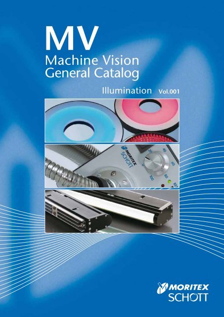
MV<br />
<strong>Machine</strong> <strong>Vision</strong><br />
General <strong>Catalog</strong><br />
<strong>Illumination</strong> <strong>Vol</strong>.<strong>001</strong>
Introduction<br />
Unparalleled Expertise<br />
<strong>Machine</strong> <strong>Vision</strong> Systems combine lighting, imaging, and data<br />
processing to inspect, monitor, and control industrial production<br />
processes. They have been employed in a variety of industries on<br />
a multitude of applications.<br />
As experts in providing Lighting and Imaging solutions for<br />
today’s vast machine vision market, MORITEX and SCHOTT<br />
offer standard and customized solutions for illumination, lens<br />
design, and front end optical systems.<br />
With decades of experience, and extensive know-how, MORITEX<br />
and SCHOTT can provide the total machine vision illumination<br />
and imaging solution designed exclusively for you comprised<br />
from our vast product portfolio.<br />
MORITEX and SCHOTT are leading global suppliers of<br />
illumination and imaging components for machine vision<br />
applications. Our unparalleled expertise in these areas makes<br />
us uniquely qualified to service all different levels from system<br />
design to integrated lighting and imaging system solutions.<br />
Please review the products featured in this catalog and let us<br />
know how we can best serve you!<br />
i-2
Your Global Lighting and Imaging Alliance<br />
Since 2007, MORITEX and SCHOTT have cooperated on a global scale.<br />
Our goal has always been to provide the ultimate products and services to<br />
our customers worldwide. By utilizing the bundled experience and expertise<br />
of these two established companies, we have made this goal a reality.<br />
As an established leader in machine vision systems with an impeccable<br />
track record of innovation, MORITEX is the only provider that can service<br />
all different levels from system design to integrated system solutions.<br />
The SCHOTT Lighting and Imaging division offers a broad range of LED<br />
and fiber optic solutions focusing on illumination, light and image<br />
transmission. In addition, SCHOTT also offers superior hybrid solutions<br />
utilizing the best of LED and fiber optic technologies.<br />
For the first time, MORITEX and SCHOTT present their entire <strong>Machine</strong><br />
<strong>Vision</strong> portfolio together in one catalog at your convenience and reference.<br />
Thank you for taking the time to learn about MORITEX and SCHOTT and<br />
how we can provide you with the ultimate in <strong>Machine</strong> <strong>Vision</strong> solutions.<br />
If you would like more information about any of our products, please don’t<br />
hesitate to contact us.<br />
MORITEX and SCHOTT, Unparalleled Expertise!<br />
i-3
Locations<br />
Spanning the Globe<br />
At MORITEX and SCHOTT we're here to serve you!<br />
With locations spanning more then 40 countries across the globe, we're almost<br />
guaranteed to have an office near you.<br />
This map represents some of our main offices serving the <strong>Machine</strong> <strong>Vision</strong><br />
industry located in Asia, Europe and the USA.<br />
Please don't hesitate to contact us if we can be of service to you. You may refer<br />
to the back cover page for contact information.<br />
San Jose<br />
U.S.A.<br />
Paris<br />
France<br />
Mainz<br />
Germany<br />
Stafford<br />
United Kingdom<br />
Tiel<br />
Netherlands<br />
Yehud<br />
Israel<br />
Tokyo<br />
Japan<br />
Singapore<br />
Shanghai<br />
China<br />
Hong Kong<br />
China<br />
Taipei<br />
Taiwan<br />
i-4
New Products<br />
LED <strong>Illumination</strong><br />
MCV-Light Series<br />
Designed to meet the rigorous needs of industrial<br />
applications, all constant voltage controlled<br />
MCV-Light Series models operate at 24V allowing<br />
for easy connection to available power supplies in<br />
addition to proprietary controllers. This series adds<br />
to the largest and most diverse product offering<br />
available in the industry.<br />
NEW<br />
P.i-10<br />
MG-Wave Series<br />
High Brightness (HB) LED Light Line<br />
SMT<br />
The latest series of SMT HB LED Light Lines provide<br />
extremely high brightness illumination (over 2M lux) while<br />
maintaining high uniformity for challenging line scan<br />
applications in a slim, light-weight design at lengths of up<br />
to 3m. Available in red and white, both the standard &<br />
reflective models have air and water-cooling options.<br />
NEW<br />
P.i-68<br />
LLS2 / MHAA and MHAB Series<br />
LED Light Source<br />
LLS2<br />
NEW<br />
The LLS2 features optimal light output with<br />
parallel 8 bit digital and 0-5V analog control.<br />
This long-life, low power consumption light<br />
source can be used as a drop-in replacement<br />
for the Halogen based MHAA Series models.<br />
P.i-98<br />
i-5
System Flow Chart<br />
LED Controller<br />
for MCV-Light Series<br />
APS<br />
Direct Ring <strong>Illumination</strong><br />
R / SQ<br />
Low Angle Ring <strong>Illumination</strong><br />
RLA / RLA-00<br />
Shadowless <strong>Illumination</strong><br />
FR / DR / DSQ<br />
Bar <strong>Illumination</strong><br />
BA<br />
LED <strong>Illumination</strong> Fiber Optic Light Sources and Light Guides<br />
LED Controller<br />
for MG-Wave Series<br />
MLEK<br />
A080W Analog Series<br />
A080W Digital Series<br />
A230W Analog Series<br />
A230W Digital Series<br />
Multi Channel Series<br />
High Wattage Series<br />
LED Controller<br />
for MCEP/MSPP Series<br />
MLEP<br />
A035W Analog Series<br />
A035W Digital Series<br />
A070W Analog Series<br />
A070W Digital Series<br />
LED Controller<br />
for MLNX Series<br />
MLEX<br />
A600W Digi/Ana<br />
Halogen Light Sources<br />
MHAA / AB<br />
MHAB-IR<br />
LED Light Source<br />
LLS2<br />
LED Light Source<br />
LLS<br />
Halogen Light Source<br />
DCR ® III<br />
DCR ® III Plus<br />
DCR ® IV<br />
Halogen Light Source<br />
ACE ®<br />
Xenon Flash Light Source<br />
MaVi-S<br />
720mm<br />
840mm<br />
Adapter<br />
for MORITEX<br />
Direct Ring <strong>Illumination</strong><br />
MDRL<br />
Low Angle Ring <strong>Illumination</strong><br />
MLRL<br />
Shadowless <strong>Illumination</strong><br />
MSRL / MSLL / MSQL<br />
Bar <strong>Illumination</strong><br />
MBRL<br />
Square Bar Type <strong>Illumination</strong><br />
MDQL<br />
Dome <strong>Illumination</strong><br />
MDML<br />
High Power LED Spot <strong>Illumination</strong><br />
MCEP<br />
LED Spot Projectors<br />
MSPP<br />
High Brightness (HB) LED Light Line<br />
MLNX<br />
Ring Light Guides<br />
MRG/P<br />
Straight Light Guides<br />
MSG/P<br />
Bifurcated Light Guides<br />
MWG/P<br />
Multifurcated Light Guides<br />
M#G#<br />
Plate Type Light Guides<br />
MPP<br />
Line Light Guides<br />
MKG/P<br />
Long Width Line Light Guides<br />
MFKG/P<br />
Universal Ringlight<br />
Midi and Mini Ringlights<br />
Ringlights, 66 mm /58 mm<br />
Darkfield Ringlight<br />
Single Bundles<br />
Dual and Quad Bundles<br />
Randomized and Calibrated Bundles<br />
Single and Dual Goosenecks<br />
Combination Goosenecks & Bundles<br />
Lightlines, 1", 2", & 3"<br />
Lightlines<br />
Spatially Randomized Lightlines<br />
Lightline, 45°<br />
Lightline Lenses<br />
Single and Dual Backlights<br />
PANELite® Backlights<br />
i-6
Square Bar Type <strong>Illumination</strong><br />
BAQ<br />
Simulated Coaxial <strong>Illumination</strong><br />
CX<br />
Direct Backlights (Chip Mount Type)<br />
FL<br />
Options<br />
Simulated Coaxial <strong>Illumination</strong><br />
MSCL<br />
Direct Backlights (Chip Mount Type)<br />
MDBC / MQFC<br />
Direct Backlights (Discrete Type)<br />
MDBL<br />
Edge Type Backlights<br />
MEBL / MEBC<br />
Collimated Backlight <strong>Illumination</strong><br />
MCBP<br />
IR <strong>Illumination</strong><br />
IR<br />
UV <strong>Illumination</strong><br />
UV<br />
Variable Color RGB <strong>Illumination</strong><br />
RGB<br />
Diffuse Chip Type Bar <strong>Illumination</strong><br />
MBRC<br />
Line <strong>Illumination</strong><br />
MLNL<br />
Coaxial <strong>Illumination</strong><br />
MCEC / MCEL<br />
Options<br />
Guidance<br />
LED <strong>Illumination</strong><br />
MCV-Light Series<br />
High Brightness (HB) LED Light Line<br />
SMT<br />
LED <strong>Illumination</strong><br />
MG-Wave Series<br />
Fiber Optic Light Sources and Light Guides<br />
MHAA and MHAB Series<br />
Condenser Lenses<br />
Light Guide Options<br />
Fiber Optic Light Sources and Light Guides<br />
Cold<strong>Vision</strong> Series<br />
Quartz UV Light Guides<br />
Darkfield Illuminator / Ringlight Adapters<br />
Ringlight Polarizers & Analyzers<br />
Diffuse Dome<br />
Ringlight Reflector Rings / Ringlight Support Apparatus<br />
Bundle Extenders<br />
Gooseneck & Bundle Support Apparatus<br />
Support Apparatus<br />
Filters, Diffusers & Spot Lenses<br />
Lightline Linear Polarizer Kits<br />
Lightlines Support Apparatus<br />
Special Application Light Guides<br />
Quartz UV Light Guides<br />
UV<br />
i-7
LED <strong>Illumination</strong><br />
Broad range of lighting solutions<br />
MORITEX and SCHOTT's has the most complete LED illumination portfolio available with<br />
the constant current controlled "MG-Wave Series" and constant voltage controlled<br />
"MCV-Light Series" providing support for the entire range of modern-day users in various<br />
image processing environments.<br />
LED <strong>Illumination</strong><br />
Image processing total system solutions support<br />
Our total system solutions approach provides customers with the best performance & efficiency<br />
through consideration of the 3 essential imaging fields of illumination, lens, and peripherals.<br />
Selection of LED <strong>Illumination</strong><br />
Making obscure and unrecognizable images<br />
become sharp and clear<br />
Our total system solutions meet a wide range of needs for image processing applications.<br />
MCV-Light Series<br />
NEW<br />
Constant <strong>Vol</strong>tage Control System / 24V DC /<br />
Industrial Design with Metal Connectors<br />
The MCV-Light Series constant voltage control LED illumination<br />
products are 24V DC driven and can be controlled by<br />
proprietary APS LED controllers as well as other available<br />
industrial 24V power supplies. Over-driven strobing is also<br />
possible for instantaneous, high intensity illumination. This<br />
series can be used in various machine vision imaging<br />
environments providing a broad range of lighting solutions.<br />
MG-Wave Series<br />
Constant Current Control System /<br />
Extensive Product Variety /<br />
Unique, High End Solutions<br />
The MG-Wave Series is our original LED illumination product<br />
line designed with our patented highly sophisticated integrated<br />
constant current sensing control system that enables our LED<br />
controllers to identify the appropriate current value for each<br />
individual LED unit connected and control them separately. The<br />
constant current design successfully reduces heat generation to<br />
improve output intensity, efficiency, and stability.<br />
i-8
Selection flowchart<br />
Identify<br />
object<br />
& FOV<br />
Select camera,<br />
lens, and<br />
peripherals<br />
Choose LED<br />
configuration,<br />
type, and<br />
wavelength<br />
Choose LED<br />
controller<br />
(i.e. drive method)<br />
Test system<br />
for proof<br />
of concept<br />
Complete<br />
setup<br />
*Refer to <strong>Machine</strong> <strong>Vision</strong><br />
General <strong>Catalog</strong> “Lens”<br />
MCV-Light<br />
MG-Wave<br />
LED Lineup Reference Table<br />
<strong>Illumination</strong> Type<br />
Direct Ring <strong>Illumination</strong><br />
Low Angle Ring <strong>Illumination</strong><br />
Shadowless <strong>Illumination</strong><br />
Bar <strong>Illumination</strong><br />
Square Bar Type <strong>Illumination</strong><br />
Dome <strong>Illumination</strong><br />
Simulated Coaxial <strong>Illumination</strong><br />
Direct Backlighting (Chip Mount Type)<br />
Direct Backlighting (Discrete Type)<br />
Edge Type Backlighting<br />
Collimated Backlight <strong>Illumination</strong><br />
High Brightness LED Light Line<br />
Line <strong>Illumination</strong><br />
Diffuse Chip Type Bar <strong>Illumination</strong><br />
High Power LED Spot <strong>Illumination</strong><br />
Coaxial <strong>Illumination</strong><br />
LED Spot Projector<br />
IR <strong>Illumination</strong><br />
UV <strong>Illumination</strong><br />
Variable Color RGB <strong>Illumination</strong><br />
24V DC Driven<br />
Controlled by proprietary APS LED controllers<br />
as well as other available industrial 24V power<br />
suppliers. Over-driven strobing and branched<br />
connection also available.<br />
Extensive Product Variety<br />
More than 350 models with low heat<br />
generation and high luminance efficiency<br />
MCV-Light Sereis<br />
R<br />
SQ<br />
RLA<br />
RLA-00<br />
FR<br />
DR<br />
DSQ<br />
BA<br />
BAQ<br />
CX<br />
FL<br />
MG-Wave Series<br />
MDRL<br />
MLRL<br />
MSRL<br />
MSLL<br />
MSQL<br />
MBRL<br />
MDQL<br />
MDML<br />
MSCL<br />
MDBC<br />
MQFC<br />
MDBL<br />
MEBL<br />
MEBC<br />
MCBP<br />
MLNX<br />
SMT<br />
MLNL<br />
MBRC<br />
MCEP<br />
MCEC<br />
MCEL<br />
MSPP<br />
IR<br />
UV<br />
RGB<br />
24V DC Input<br />
DIN Rail Mountable<br />
Analog 2-channel LED controller<br />
without external control<br />
100-240V AC Input Analog & Digital<br />
Controllers with External Control<br />
Input<br />
Channel<br />
External<br />
Control<br />
1-ch, 2-ch, & 4-ch models available;<br />
3-ch available for MCEP Series<br />
MCV-Light<br />
MG-Wave<br />
MCV-Light<br />
MG-Wave<br />
MCV-Light<br />
MG-Wave<br />
DC24V<br />
AC100V~240V<br />
2ch<br />
1ch, 2ch, 4ch<br />
N/A<br />
Analog (0-5V)<br />
Digital (Pararell/8bit)<br />
LED Controller Lineup Reference<br />
Analog LED Controllers<br />
for MCV-Light Series<br />
24V DC, DIN rail mountable<br />
LED Controllers<br />
for MG-Wave Series<br />
Constant current sensing<br />
control system<br />
LED Controllers<br />
for MCEP/MSPP Series<br />
For high power LED spot<br />
illumination<br />
LED <strong>Illumination</strong><br />
Selection of LED <strong>Illumination</strong><br />
LED Controllers<br />
for MLNX Series<br />
Applicable lighting length:<br />
840-2880mm<br />
i-9
LED <strong>Illumination</strong><br />
LED <strong>Illumination</strong><br />
MC V- Light Series<br />
24V DC Driven / Industrial Design with Metal Connectors<br />
MCV-Light Series<br />
MCV-Light Series employs the constant voltage control system that can be<br />
controlled not only by APS LED controllers but also by industry available 24V<br />
DC power supplies directly. Overdriven strobing for instantaneous high intensity<br />
illumination is also available. The series can support customer’s various image<br />
processing environments with a broad range of lighting solutions.<br />
LED Controller<br />
for MCV-Light Series<br />
APS<br />
Direct Ring <strong>Illumination</strong><br />
R / SQ<br />
Low Angle Ring <strong>Illumination</strong><br />
RLA / RLA-00<br />
Shadowless <strong>Illumination</strong><br />
FR / DR / DSQ<br />
Bar <strong>Illumination</strong><br />
BA<br />
Square Bar Type <strong>Illumination</strong><br />
BAQ<br />
Simulated Coaxial <strong>Illumination</strong><br />
CX<br />
Direct Backlights (Chip Mount Type)<br />
FL<br />
Options<br />
i-10
LED <strong>Illumination</strong><br />
MC V- Light Series<br />
LED SAFETY STANDARD (CEI/IEC 62471:2006)<br />
Groups<br />
Exempt<br />
Definition and Emission limit<br />
Not more than 1.0 W·m -2 . Small source<br />
defined as one with
LED <strong>Illumination</strong><br />
MCV-Light Series<br />
Direct Ring <strong>Illumination</strong><br />
R/SQ Series<br />
RoHS<br />
CE<br />
Direct Ring <strong>Illumination</strong><br />
R Series<br />
SQ Series<br />
R / SQ<br />
Direct Ring <strong>Illumination</strong>: R Series<br />
• High intensity, uniform direct, bright-field 360-degree lighting<br />
Explanation of Model Code<br />
R - X -<br />
• Standard LED illumination for a wide range of applications<br />
External<br />
Diameter<br />
Internal<br />
Diameter<br />
Lighting<br />
Angle<br />
Emitted<br />
Color<br />
Square Ring <strong>Illumination</strong>: SQ Series<br />
• Ring illumination with LEDs mounted vertically onto a planar<br />
substrate in a square chassis<br />
SQ - X X<br />
External Dimensions<br />
Length<br />
Width<br />
Internal<br />
Diameter<br />
Emitted<br />
Color<br />
Lineup of Direct Ring Type LEDs<br />
Model<br />
Emitted<br />
Color<br />
Power<br />
(W)<br />
Lineup of Square Ring Type LEDs<br />
Internal External<br />
Lighting<br />
Diameter Diameter<br />
Angle<br />
(mm) (mm)<br />
Weight<br />
(g)<br />
Product<br />
Code<br />
R-32X10-70R Red 1.5 32 10 70˚ 50 A-2600<br />
R-32X10-70B Blue 2.1 32 10 70˚ 50 A-2602<br />
R-32X10-70W White 2.1 32 10 70˚ 50 A-2601<br />
R-42X18-65R Red 1.8 42 18 65˚ 75 A-2603<br />
R-42X18-65B Blue 2.8 42 18 65˚ 75 A-2605<br />
R-42X18-65W White 2.8 42 18 65˚ 75 A-2604<br />
R-50X28-75R Red 2.1 50 28 75˚ 75 A-2606<br />
R-50X28-75B Blue 3.6 50 28 75˚ 75 A-2608<br />
CCD<br />
R-50X28-75W White 3.6 50 28 75˚ 75 A-2607<br />
R-70X35-90R Red 4.2 70 35 90˚ 150 A-2609<br />
R-70X35-90B Blue 6.6 70 35 90˚ 150 A-2611<br />
R-70X35-90W White 6.6 70 35 90˚ 150 A-2610<br />
R-90X30-80R Red 8.1 90 30 83˚ 250 A-2612<br />
R-90X30-80B Blue 9.6 90 30 83˚ 250 A-2614<br />
R-90X30-80W White 9.6 90 30 83˚ 250 A-2613<br />
R-90X50-70R Red 6.1 90 50 71˚ 200 A-2615<br />
R-90X50-70B Blue 8.3 90 50 71˚ 200 A-2617<br />
R-90X50-70W White 8.3 90 50 71˚ 200 A-2616<br />
<br />
R-120X60-50R Red 8.4 120 60 52˚ 550 A-2618<br />
R-120X60-50B Blue 17 120 60 52˚ 550 A-2620<br />
R-120X60-50W White 17 120 60 52˚ 550 A-2619<br />
Model<br />
Emitted<br />
Color<br />
Power<br />
(W)<br />
External Dimensions (mm)<br />
Length<br />
Width<br />
Internal Weight Product<br />
Diameter (g) Code<br />
SQ-56X56X30R Red 2.1 56 56 30 100 A-2776<br />
SQ-56X56X30B Blue 3.3 56 56 30 100 A-2778<br />
SQ-56X56X30W White 3.3 56 56 30 100 A-2777<br />
<br />
<strong>Illumination</strong> Structure<br />
R Series<br />
SQ Series<br />
CCD Camera <br />
Lens<br />
Lens<br />
Object<br />
<br />
Object<br />
i-12
R-32X10-70R (B,W)<br />
R-42X18-65R (B,W)<br />
ø10<br />
4-M3x4mm Depth PCD 20<br />
Equidistribution<br />
4-M3 4 PCD20<br />
ø18<br />
4-M3x4mm Depth PCD 28<br />
Equidistribution<br />
4-M3 4 PCD28<br />
45<br />
45<br />
16<br />
ø32 500<br />
70<br />
(3.1)<br />
(ø4)<br />
(60)<br />
(20)<br />
(46.8)<br />
(ø15.3)<br />
CN1<br />
4<br />
1 3<br />
2<br />
18<br />
ø42<br />
65<br />
(3.1)<br />
(ø4)<br />
500 (46.8)<br />
(60)<br />
(20)<br />
(ø15.3)<br />
CN1<br />
4<br />
1 3<br />
2<br />
R-50X28-75R (B,W)<br />
R-70X35-90R (B,W)<br />
ø28<br />
4-M3x4mm Depth PCD 40<br />
Equidistribution<br />
4-M3 4 PCD40<br />
ø35 4-M3x4mm Depth PCD 50<br />
Equidistribution<br />
4-M3 4 PCD50<br />
16<br />
ø50<br />
75<br />
45<br />
(3.1)<br />
R-90X30-80R (B,W)<br />
(ø4)<br />
500<br />
(60)<br />
(20)<br />
ø30 4-M3x4mm Depth PCD 70<br />
Equidistribution<br />
4-M3 4 PCD70<br />
(46.8)<br />
(ø15.3)<br />
CN1<br />
4<br />
1 3<br />
2<br />
ø70<br />
22<br />
(6)<br />
(ø4)<br />
500<br />
(60)<br />
R-90X50-70R (B,W)<br />
45<br />
(20)<br />
ø50 4-M3x4mm Depth PCD 70<br />
Equidistribution<br />
4-M3 4 PCD70<br />
(46.8)<br />
(ø15.3)<br />
CN1<br />
4<br />
1 3<br />
2<br />
Direct Ring <strong>Illumination</strong><br />
20<br />
83<br />
ø90<br />
45<br />
(3.1)<br />
(ø4)<br />
500 (46.8)<br />
(60)<br />
(20)<br />
(ø15.3)<br />
CN1<br />
4<br />
1 3<br />
2<br />
20<br />
71<br />
ø90<br />
45<br />
(3.1)<br />
(ø4)<br />
500 (46.8)<br />
(60)<br />
(20)<br />
(15.3)<br />
CN1<br />
4<br />
1 3<br />
2<br />
R / SQ<br />
R-120X60-50R (B,W)<br />
SQ-56X56X30R (B,W)<br />
ø60<br />
4-M3x4mm Depth PCD 90<br />
Equidistribution<br />
4-M3 4 PCD90<br />
38<br />
ø30<br />
4-M3x3mm Tap Depth<br />
4-M3 3<br />
56<br />
38<br />
45<br />
31.5<br />
52<br />
ø120<br />
(15.6)<br />
(ø4)<br />
500<br />
(60)<br />
(20)<br />
(46.8)<br />
(ø15.3)<br />
CN1<br />
4<br />
1 3<br />
2<br />
18<br />
56 500 (46.8)<br />
(4)<br />
(ø4)<br />
(60)<br />
46<br />
(20)<br />
(ø15.3)<br />
CN1<br />
4<br />
1 3<br />
2<br />
4-M2x3mm Tap Depth<br />
4-M2 3<br />
46<br />
Relative Intensity<br />
Relative Intensity<br />
1.0<br />
0.8<br />
0.6<br />
0.4<br />
0.2<br />
Light Distribution Characteristics<br />
R-42X18-65W<br />
R-70X35-90W<br />
R-90X50-70W<br />
1.2<br />
1.2<br />
Relative Intensity<br />
0.0<br />
0.0<br />
-60 -40 -20 0 20 40 60 -150 -100 -50 0 50 100 150<br />
Distance From Center (X-Axis) (mm)<br />
Distance From Center (X-Axis) (mm)<br />
WD=5 WD=10 WD=20 WD=30 WD=40<br />
WD=35 WD=45 WD=60 WD=80 WD=100<br />
SQ-56X56X30W<br />
1.2<br />
1.0<br />
0.8<br />
0.6<br />
0.4<br />
0.2<br />
0.0<br />
-100 -80 -60 -40 -20 0 20 40 60 80 100<br />
Distance From Center (X-Axis) (mm)<br />
WD=25 WD=35 WD=50 WD=65 WD=80<br />
1.0<br />
0.8<br />
0.6<br />
0.4<br />
0.2<br />
Relative Intensity<br />
1.2<br />
1.0<br />
0.8<br />
0.6<br />
0.4<br />
0.2<br />
0.0<br />
-150 -100 -50 0 50 100 150<br />
Distance From Center (X-Axis) (mm)<br />
WD=25 WD=35 WD=45 WD=60 WD=80<br />
i-13
LED <strong>Illumination</strong><br />
MCV-Light Series<br />
R Series<br />
Sample Images<br />
Foreign Object in Paper Cup<br />
PCB Fabrication Inspection<br />
Direct Ring <strong>Illumination</strong><br />
SQ Series<br />
Not Much Light at Short WD<br />
Full Light at Longer WD<br />
R / SQ<br />
Accessories<br />
Adapter Diffuser Polarizer Method of Mounting<br />
AD-Rxx<br />
R Series<br />
Used to mount<br />
the diffuser or<br />
polarizer onto the<br />
LED lighting.<br />
DF-Rxx<br />
DF-SQxx<br />
To be mounted in front of<br />
the LED lighting using the<br />
adapter. Used to soften<br />
the lighting output, so<br />
as to reduce the glare on<br />
specular surface.<br />
PL-Rxx<br />
PL-SQxx<br />
To be mounted in front of<br />
the LED lighting using the<br />
adapter. Use together with<br />
second polarizer(analyzer)<br />
to help reduce glare.<br />
LED <strong>Illumination</strong><br />
Diffuser/Polarizer<br />
Adapter<br />
The adapter is used to hold the diffuser/<br />
polarizer to the LED lighting.<br />
SQ Series<br />
Model Product Type Compatible Light Models Product Code<br />
AD-R32X10 Adapter R-32x10-70R/B/W A-2812<br />
DF-R32X10 Diffuser R-32x10-70 A-2813<br />
PL-R32X10 Polarizer R-32x10-70 A-2814<br />
AD-R42X18 Adapter R-42x18-65 A-2815<br />
DF-R42X18 Diffuser R-42x18-65 A-2816<br />
PL-R42X18 Polarizer R-42x18-65 A-2817<br />
AD-R50X28 Adapter R-50x28-75 A-2818<br />
DF-R50X28 Diffuser R-50x28-75 A-2819<br />
PL-R50X28 Polarizer R-50x28-75 A-2820<br />
AD-R70X35 Adapter R-70x35-90 A-2821<br />
DF-R70X35 Diffuser R-70x35-90 A-2822<br />
PL-R70X35 Polarizer R-70x35-90 A-2823<br />
AD-R90X50 Adapter R-90x50-70 A-2824<br />
DF-R90X50 Diffuser R-90x50-70 A-2825<br />
PL-R90X50 Polarizer R-90x50-70 A-2826<br />
AD-R120X60 Adapter R-120x60-50 A-2827<br />
DF-R120X60 Diffuser R-120x60-50 A-2828<br />
PL-R120X60 Polarizer R-120x60-50 A-2829<br />
DF-SQ56X56X30 Diffuser SQ-56x56x30 A-2858<br />
PL-SQ56X56X30 Polarizer SQ-56x56x30 A-2859<br />
Screws<br />
The given screws are used<br />
to hold the diffuser/polarizer<br />
to the LED lighting.<br />
LED<br />
<strong>Illumination</strong><br />
Diffuser/<br />
Polarizer<br />
i-14
Low Angle Ring <strong>Illumination</strong><br />
RLA/RLA-00 Series<br />
RoHS<br />
CE<br />
RLA Series<br />
RLA-00 Series<br />
Low Angle Ring <strong>Illumination</strong><br />
Low Angle Ring <strong>Illumination</strong>: RLA Series<br />
• Reflection can be minimized by the low-angle, dark-field lighting<br />
configuration<br />
• Ideal for imaging of uneven surfaces, eg. embossment and<br />
surface flaw detection<br />
Explanation of Model Code<br />
RLA - X -<br />
External<br />
Diameter<br />
Internal<br />
Diameter<br />
Lighting<br />
Angle<br />
Emitted<br />
Color<br />
RL A / RL A - 0 0<br />
Zero Angle Ring <strong>Illumination</strong>: RLA-00 Series<br />
• Indirect, horizontal 360-degree inner diameter illumination<br />
• Used at a short WD to the test object<br />
Lineup of Low Angle Ring Type LEDs<br />
Model<br />
Emitted<br />
Color<br />
Power<br />
(W)<br />
Internal<br />
Diameter<br />
(mm)<br />
External<br />
Lighting Weight<br />
Diameter<br />
Angle (g)<br />
(mm)<br />
Product<br />
Code<br />
RLA-74X48-30R Red 4.0 74 48 30˚ 120 A-2631<br />
RLA-74X48-30B Blue 5.4 74 48 30˚ 120 A-2633<br />
RLA-74X48-30W White 5.4 74 48 30˚ 120 A-2632<br />
RLA-100X70-30R Red 6.3 100 70 30˚ 190 A-2634<br />
RLA-100X70-30B Blue 9.8 100 70 30˚ 190 A-2636<br />
RLA-100X70-30W White 9.8 100 70 30˚ 190 A-2635<br />
RLA-132X96-15R Red 7.7 132 96 15˚ 300 A-2637<br />
RLA-132X96-15B Blue 14 132 96 15˚ 300 A-2639<br />
RLA-132X96-15W White 14 132 96 15˚ 300 A-2638<br />
Lineup of Zero Angle Ring Type LEDs<br />
Model<br />
Emitted<br />
Color<br />
Power<br />
(W)<br />
Internal<br />
Diameter<br />
(mm)<br />
External<br />
Lighting Weight Product<br />
Diameter<br />
Angle (g) Code<br />
(mm)<br />
RLA-75X46-00R Red 1.7 75 46 0˚ 95 A-2640<br />
RLA-75X46-00B Blue 3.3 75 46 0˚ 95 A-2642<br />
RLA-75X46-00W White 3.3 75 46 0˚ 95 A-2641<br />
RLA-96X60-00R Red 2.1 96 60 0˚ 140 A-2643<br />
RLA-96X60-00B Blue 4.2 96 60 0˚ 140 A-2645<br />
RLA-96X60-00W White 4.2 96 60 0˚ 140 A-2644<br />
<strong>Illumination</strong> Structure<br />
RLA Series<br />
CCD Camera<br />
Object<br />
Lens<br />
Illuminating the Object<br />
from a Low Position<br />
RLA-00 Series<br />
CCD Camera<br />
Object<br />
Lens<br />
i-15
LED <strong>Illumination</strong><br />
MCV-Light Series<br />
RLA-74X48-30R (B,W)<br />
RLA-100X70-30R (B,W)<br />
ø48<br />
4-M3x4mm Depth PCD 60<br />
Equidistribution<br />
4-M3 4 PCD60<br />
ø70<br />
4-M3x4mm Depth PCD 84<br />
Equidistribution<br />
4-M3 4 PCD84<br />
45<br />
Low Angle Ring <strong>Illumination</strong><br />
ø74<br />
500 (46.8)<br />
19<br />
(3.1)<br />
(ø4)<br />
(20)<br />
30<br />
(60)<br />
RLA-132X96-15R (B,W)<br />
3-M3x4mm Depth PCD 116<br />
Equidistribution<br />
ø96<br />
3-M3 4 PCD116<br />
45<br />
(ø15.3)<br />
CN1<br />
4<br />
1 3<br />
2<br />
22<br />
30<br />
45<br />
ø100 500<br />
(3.1)<br />
(ø4)<br />
(60)<br />
(20)<br />
(46.8)<br />
(ø15.3)<br />
CN1<br />
4<br />
1 3<br />
2<br />
RL A / RL A - 0 0<br />
22<br />
15<br />
ø132 500 (46.8)<br />
(3.1)<br />
(ø4)<br />
(20)<br />
(60)<br />
RLA-75X46-00R (B,W)<br />
(15.3)<br />
CN1<br />
4<br />
1 3<br />
2<br />
RLA-96X60-00R (B,W)<br />
ø46<br />
4-M3x4mm Depth PCD 56<br />
Equidistribution<br />
ø60<br />
4-M3x4mm Depth PCD80<br />
Equidistribution<br />
4-M3 4 PCD80<br />
4-M3 4 PCD56<br />
45<br />
10<br />
ø75<br />
(3.5)<br />
(ø4)<br />
500<br />
(20)<br />
(46.8)<br />
(ø15.3)<br />
CN1<br />
4<br />
1 3<br />
ø96 500 (46.8)<br />
(3.5)<br />
(ø4)<br />
(20)<br />
(ø15.3)<br />
CN1<br />
4<br />
(60)<br />
2<br />
10<br />
(60)<br />
1 3<br />
2<br />
Relative Intensity<br />
1.2<br />
1.0<br />
0.8<br />
0.6<br />
0.4<br />
0.2<br />
RLA-74X48-30W<br />
0.0<br />
-80 -60 -40 -20 0 20 40 60 80<br />
Distance From Center (X-Axis) (mm)<br />
Light Distribution Characteristics<br />
Relative Intensity<br />
1.2<br />
1.0<br />
0.8<br />
0.6<br />
0.4<br />
0.2<br />
RLA-100X70-30W<br />
0.0<br />
-100 -80 -60 -40 -20 0 20 40 60 80 100<br />
Distance From Center (X-Axis) (mm)<br />
Relative Intensity<br />
1.2<br />
1.0<br />
0.8<br />
0.6<br />
0.4<br />
0.2<br />
RLA-132X96-15W<br />
0.0<br />
-150 -100 -50 0 50 100 150<br />
Distance From Center (X-Axis) (mm)<br />
WD=5 WD=15 WD=25 WD=35 WD=40<br />
WD=5 WD=10 WD=20 WD=25 WD=30 WD=5 WD=15 WD=25 WD=30 WD=35<br />
Relative Intensity<br />
1.2<br />
1.0<br />
0.8<br />
0.6<br />
0.4<br />
0.2<br />
RLA-75X46-00W<br />
0.0<br />
-60 -40 -20 0 20 40 60<br />
Distance From Center (X-Axis) (mm)<br />
WD=5 WD=10 WD=15 WD=20 WD=25<br />
Relative Intensity<br />
1.2<br />
1.0<br />
0.8<br />
0.6<br />
0.4<br />
0.2<br />
RLA-96X60-00W<br />
0.0<br />
-80 -60 -40 -20 0 20 40 60 80<br />
Distance From Center (X-Axis) (mm)<br />
WD=5 WD=10 WD=15 WD=20 WD=25<br />
i-16
RLA Series<br />
Sample Images<br />
Chamfer Checking on Metal Ring<br />
RLA-00 Series<br />
Scratch on Glass Plate<br />
12-Pin Connector<br />
CD Imprint Inspection<br />
Low Angle Ring <strong>Illumination</strong><br />
Accessories<br />
RL A / RL A - 0 0<br />
Diffuser Ring<br />
Method of Mounting<br />
DF-RLAxxx<br />
Used to create a relatively non-directional<br />
light. Reduces glare on specular surfaces.<br />
Easily mount onto Low-Angle Ring light.<br />
Diffuser<br />
Set Screws<br />
LED <strong>Illumination</strong><br />
The diffuser is mounted to the inner side of the<br />
Low-Angle Ring Light by three set screws.<br />
Model Product Type Compatible Light Models Product Code<br />
DF-RLA74X48 Diffuser Ring RLA-74x48-30 A-2830<br />
DF-RLA100X70 Diffuser Ring RLA-100x70-30 A-2831<br />
DF-RLA132X96 Diffuser Ring RLA-132x96-15 A-2832<br />
i-17
LED <strong>Illumination</strong><br />
MCV-Light Series<br />
Shadowless <strong>Illumination</strong><br />
FR/DR/DSQ Series<br />
RoHS<br />
CE<br />
Shadowless <strong>Illumination</strong><br />
DR Series<br />
FR Series<br />
FR / DR / DSQ<br />
Shadowless Ring <strong>Illumination</strong>: FR Series<br />
• Diffuse, shadowless illumination* Optimal soft, uniform light<br />
for shiny surfaces<br />
Explanation of Model Code<br />
FR -<br />
DSQ Series<br />
External<br />
Diameter<br />
X<br />
Internal<br />
Diameter<br />
Emitted<br />
Color<br />
Shadowless Low Angle Ring <strong>Illumination</strong>: DR Series<br />
DR -<br />
X<br />
• Shallow angle LED illumination that provides diffused, soft light<br />
• Ideal for flaw or edge detection on reflective surfaces<br />
External<br />
Diameter<br />
Internal<br />
Diameter<br />
Emitted<br />
Color<br />
Square Shadowless Low Angle <strong>Illumination</strong>: DSQ Series<br />
• Diffused illumination best suited for square shape objects, such<br />
as in BGA & QFP applications<br />
DSQ - X -<br />
External Dimensions<br />
Length<br />
Width<br />
Height of<br />
Lighting Surface<br />
Emitted<br />
Color<br />
<strong>Illumination</strong> Structure<br />
FR Series<br />
DR Series<br />
DSQ Series<br />
<br />
CCD<br />
Camera<br />
CCD CCD Camera<br />
CCD Camera<br />
<br />
<br />
Lens<br />
Lens <br />
Lens<br />
<br />
Object <br />
Object<br />
Object<br />
i-18
Lineup of Shadowless Ring Type LEDs<br />
Model<br />
Emitted<br />
Color<br />
Power<br />
(W)<br />
Internal<br />
Diameter<br />
(mm)<br />
External<br />
Diameter<br />
(mm)<br />
Weight<br />
(g)<br />
Product<br />
Code<br />
FR-102X33R Red 2.5 102 33 210 A-2656<br />
FR-102X33B Blue 5.1 102 33 210 A-2658<br />
FR-102X33W White 5.1 102 33 210 A-2657<br />
FR-125X44R Red 4.3 125 44 290 A-2659<br />
FR-125X44B Blue 6.3 125 44 290 A-2661<br />
FR-125X44W White 6.3 125 44 290 A-2660<br />
Lineup of Shadowless, Low Angle Ring Type LEDs<br />
Model<br />
Emitted<br />
Color<br />
Power<br />
(W)<br />
Internal<br />
Diameter<br />
(mm)<br />
External<br />
Diameter<br />
(mm)<br />
Weight<br />
(g)<br />
Product<br />
Code<br />
DR-100X73R Red 4.2 100 73 260 A-2672<br />
DR-100X73B Blue 8.4 100 73 260 A-2674<br />
DR-100X73W White 8.4 100 73 260 A-2673<br />
DR-136X109R Red 6.3 136 109 340 A-2675<br />
DR-136X109B Blue 13 136 109 340 A-2677<br />
DR-136X109W White 13 136 109 340 A-2676<br />
DR-180X153R Red 8.3 180 153 450 A-2678<br />
DR-180X153B Blue 17 180 153 450 A-2680<br />
DR-180X153W White 17 180 153 450 A-2679<br />
Lineup of Shadowless, Low Angle Square Type LEDs<br />
Model<br />
Emitted<br />
Color<br />
Power<br />
(W)<br />
External Dimensions<br />
(mm)<br />
Length<br />
Width<br />
Height of Lighting<br />
Surface<br />
(mm)<br />
Weight<br />
(g)<br />
Product<br />
Code<br />
DSQ-48X48-15R Red 1.3 48 48 15 130 A-2789<br />
DSQ-48X48-15B Blue 2.6 48 48 15 130 A-2791<br />
DSQ-48X48-15W White 2.6 48 48 15 130 A-2790<br />
DSQ-75X75-15R Red 1.7 75 75 15 200 A-2792<br />
DSQ-75X75-15B Blue 3.4 75 75 15 200 A-2794<br />
DSQ-75X75-15W White 3.4 75 75 15 200 A-2793<br />
DSQ-96X96-15R Red 2.5 96 96 15 220 A-2795<br />
DSQ-96X96-15B Blue 5.1 96 96 15 220 A-2797<br />
DSQ-96X96-15W White 5.1 96 96 15 220 A-2796<br />
DSQ-120X120-15R Red 3.4 120 120 15 260 A-2798<br />
DSQ-120X120-15B Blue 6.7 120 120 15 260 A-2800<br />
DSQ-120X120-15W White 6.7 120 120 15 260 A-2799<br />
Shadowless <strong>Illumination</strong><br />
FR / DR / DSQ<br />
i-19
LED <strong>Illumination</strong><br />
MCV-Light Series<br />
FR-102X33R (B,W)<br />
FR-125X44R (B,W)<br />
12<br />
ø102 500<br />
(9)<br />
(ø4)<br />
(20)<br />
(46.8)<br />
(ø15.3)<br />
CN1<br />
4<br />
1 3<br />
12<br />
ø125 500<br />
(9)<br />
(ø4)<br />
(20)<br />
(46.8)<br />
(ø15.3)<br />
CN1<br />
4<br />
1 3<br />
ø80(Lighting Surface)<br />
ø33<br />
(60)<br />
2<br />
ø103(Lighting Surface)<br />
ø44<br />
(60)<br />
2<br />
Shadowless <strong>Illumination</strong><br />
FR / DR / DSQ<br />
40<br />
DR-100X73R (B,W)<br />
ø73<br />
ø100<br />
ø93.5(Lighting Surface)<br />
3-M3x4mm Tap Depth on the Back<br />
PCD 70 Equidistribution<br />
3-M3 4 PCD70<br />
4-M3x4mm Depth PCD 84<br />
Equidistribution<br />
4-M3 4 PCD84<br />
500<br />
(7.5)<br />
(ø4)<br />
(20)<br />
DR-180X153R (B,W)<br />
(60)<br />
ø153<br />
4-M3x4mm Depth PCD 164<br />
Equidistribution<br />
(46.8)<br />
(ø15.3)<br />
CN1<br />
4<br />
1 3<br />
2<br />
40<br />
DR-136X109R (B,W)<br />
ø109<br />
ø136<br />
ø129.5(Lighting Surface)<br />
3-M3x4mm Tap Depth on the Back<br />
PCD 70 Equidistribution<br />
3-M3 4 PCD70<br />
4-M3x4mm Depth PCD 120<br />
Equidistribution<br />
4-M3 4 PCD120<br />
(7.5)<br />
(ø4)<br />
500<br />
(60)<br />
(20)<br />
(46.8)<br />
(ø15.3)<br />
CN1<br />
4<br />
1 3<br />
2<br />
4-M3 4 PCD164<br />
ø180<br />
(7.5)<br />
(ø4)<br />
500<br />
(20)<br />
(46.8)<br />
(ø15.3)<br />
CN1<br />
4<br />
40<br />
(60)<br />
1 3<br />
2<br />
ø173.5(Lighting Surface)<br />
DSQ-48X48-15R (B,W)<br />
DSQ-75X75-15R (B,W)<br />
30<br />
26<br />
10<br />
4-M3x3mm Tap Depth<br />
57<br />
53<br />
20<br />
4-M3x3mm Tap Depth<br />
4-M3 3<br />
4-M3 3<br />
75<br />
57<br />
53<br />
20<br />
48<br />
30<br />
26<br />
10<br />
48 500 (46.8)<br />
(ø15.3)<br />
CN1<br />
4<br />
30<br />
15(Lighting Surface)<br />
36<br />
(Lighting Surface)<br />
(4)<br />
(ø4)<br />
(60)<br />
(20)<br />
1 3<br />
2<br />
30<br />
15(Lighting Surface)<br />
75<br />
63<br />
(Lighting Surface)<br />
(4)<br />
(ø4)<br />
500 (46.8)<br />
(60)<br />
(20)<br />
(15.3)<br />
CN1<br />
4<br />
1 3<br />
2<br />
DSQ-96X96-15R (B,W)<br />
DSQ-120X120-15R (B,W)<br />
78<br />
74<br />
4-M3x3mm Tap Depth<br />
4-M3 3<br />
102<br />
98<br />
4-M3x3mm Tap Depth<br />
4-M3 3<br />
30<br />
15(Lighting Surface)<br />
96<br />
78<br />
74<br />
120<br />
102<br />
98<br />
96 500 (46.8)<br />
84<br />
(Lighting Surface)<br />
(4)<br />
(ø4)<br />
(20)<br />
(60)<br />
(ø15.3)<br />
CN1<br />
4<br />
1 3<br />
2<br />
30<br />
15(Lighting Surface)<br />
120 500 (46.8)<br />
108<br />
(Lighting Surface)<br />
(4)<br />
(ø4)<br />
(20)<br />
(60)<br />
(ø15.3)<br />
CN1<br />
4<br />
1 3<br />
2<br />
i-20
Relative Intensity<br />
1.2<br />
1.0<br />
0.8<br />
0.6<br />
0.4<br />
0.2<br />
Light Distribution Characteristics<br />
FR-102X33W<br />
FR-125X44W<br />
0.0<br />
-150 -100 -50 0 50 100 200<br />
Distance From Center (X-Axis) (mm)<br />
WD=20 WD=25 WD=30 WD=40 WD=50<br />
Relative Intensity<br />
1.2<br />
1.0<br />
0.8<br />
0.6<br />
0.4<br />
0.2<br />
0.0<br />
-200 -150 -100 -50 0 50 100 150 200<br />
Distance From Center (X-Axis) (mm)<br />
WD=35 WD=40 WD=50 WD=60 WD=80<br />
Relative Intensity<br />
1.2<br />
1.0<br />
0.8<br />
0.6<br />
0.4<br />
0.2<br />
DR100X73W<br />
0.0<br />
-100 -80 -60 -40 -20 0 20 40 60 80 100<br />
Distance From Center (X-Axis) (mm)<br />
WD=25 WD=35 WD=45 WD=60 WD=80<br />
Relative Intensity<br />
1.2<br />
1.0<br />
0.8<br />
0.6<br />
0.4<br />
0.2<br />
DR-136X109W<br />
0.0<br />
-200 -150 -100 -50 0 50 100 150 200<br />
Distance From Center (X-Axis) (mm)<br />
WD=40 WD=50 WD=60 WD=80 WD=100<br />
Relative Intensity<br />
1.2<br />
1.0<br />
0.8<br />
0.6<br />
0.4<br />
0.2<br />
DR-180X153W<br />
0.0<br />
-300 -200 -100 0 100 200 300<br />
Distance From Center (X-Axis) (mm)<br />
WD=50 WD=60 WD=80 WD=100 WD=120<br />
Shadowless <strong>Illumination</strong><br />
Relative Intensity<br />
DSQ-48X48-15W<br />
DSQ-75X75-15W<br />
DSQ-120X120-15W<br />
1.2<br />
1.0<br />
0.8<br />
0.6<br />
0.4<br />
0.2<br />
0.0<br />
-80 -60 -40 -20 0 20 40 60 80<br />
Distance From Center (X-Axis) (mm)<br />
Relative Intensity<br />
1.2<br />
1.0<br />
0.8<br />
0.6<br />
0.4<br />
0.2<br />
0.0<br />
-100 -80 -60 -40 -20 0 20 40 60 80 100<br />
Distance From Center (X-Axis) (mm)<br />
Relative Intensity<br />
1.2<br />
1.0<br />
0.8<br />
0.6<br />
0.4<br />
0.2<br />
0.0<br />
-200 -150 -100 -50 0 50 100 150 200<br />
Distance From Center (X-Axis) (mm)<br />
FR / DR / DSQ<br />
WD=5 WD=10 WD=15 WD=20 WD=30<br />
WD=5 WD=15 WD=25 WD=35 WD=45<br />
WD=20 WD=30 WD=45 WD=60 WD=80<br />
FR Series<br />
Sample Images<br />
DR Series<br />
CD Inspection<br />
DSQ Series<br />
OCR on Brushed Metal Surface<br />
Cap Inspection<br />
Silkscreen Printing Verification for<br />
Remote Control<br />
Connector Inspection<br />
Ink Cartridge Print Head Inspection<br />
i-21
LED <strong>Illumination</strong><br />
MCV-Light Series<br />
Bar <strong>Illumination</strong><br />
RoHS<br />
CE<br />
BA Series<br />
Bar <strong>Illumination</strong><br />
BA<br />
• High-intensity LED block array<br />
• Can be directed at any angle to the surface for either direct or<br />
optimal oblique lighting<br />
Explanation of Model Code<br />
BA - X<br />
Lighting Area Dimensions<br />
Length Width<br />
Emitted<br />
Color<br />
Model<br />
Emitted<br />
Color<br />
Power<br />
(W)<br />
Lighting Area<br />
Dimensions (mm)<br />
Length<br />
Width<br />
Weight<br />
(g)<br />
Product<br />
Code<br />
BA-42X15R Red 1.4 42 15 65 A-2691<br />
BA-42X15B Blue 2.0 42 15 65 A-2693<br />
BA-42X15W White 2.0 42 15 65 A-2692<br />
BA-74X27R Red 3.1 74 27 130 A-2694<br />
BA-74X27B Blue 5.0 74 27 130 A-2696<br />
BA-74X27W White 5.0 74 27 130 A-2695<br />
BA-82X15R Red 2.1 82 15 85 A-2697<br />
BA-82X15B Blue 3.9 82 15 85 A-2699<br />
BA-82X15W White 3.9 82 15 85 A-2698<br />
BA-130X15R Red 3.4 130 15 130 A-2700<br />
BA-130X15B Blue 6.2 130 15 130 A-2702<br />
BA-130X15W White 6.2 130 15 130 A-2701<br />
CCD<br />
<br />
<br />
<strong>Illumination</strong> Structure<br />
CCD Camera<br />
Lens<br />
Object<br />
i-22
BA-42X15R (B,W)<br />
BA-74X27R (B,W)<br />
4-M2x4mm Tap Depth<br />
(Including Opposite Face)<br />
4-M2 4()<br />
5.5 9<br />
17<br />
21.5<br />
15(Lighting Area)<br />
52<br />
47<br />
42(Lighting Area)<br />
(10)<br />
(ø4)<br />
2-M2x4mm Tap Depth<br />
2-M2 4<br />
(60)<br />
(20)<br />
500 (46.8)<br />
(ø15.3)<br />
CN1<br />
4<br />
1 3<br />
2<br />
29<br />
27(Lighting Area)<br />
18.5<br />
80<br />
74(Lighting Area)<br />
86<br />
50<br />
2-M2x4mm Tap Depth<br />
2-M2 4<br />
500 (46.8)<br />
(10.7)<br />
(ø4)<br />
(60)<br />
(20)<br />
(ø15.3)<br />
CN1<br />
4<br />
1 3<br />
2<br />
2-M3x4mm Tap Depth<br />
2-M3 4<br />
2-M3x4mm Tap Depth<br />
22<br />
2-M3 4<br />
BA-82X15R (B,W)<br />
BA-130X15R (B,W)<br />
17<br />
15(Lighting Area)<br />
4-M2x4mm Tap Depth<br />
(Including Opposite Face)<br />
4-M2 4()<br />
92<br />
87<br />
82(Lighting Area)<br />
5.5 9<br />
21.5<br />
(ø4)<br />
(10)<br />
2-M3x4mm Tap Depth<br />
2-M3 4<br />
2-M2x4mm Tap Depth<br />
2-M2 4<br />
(60)<br />
(20)<br />
500 (46.8)<br />
(ø15.3)<br />
CN1<br />
4<br />
1 3<br />
2<br />
5.5 9<br />
17<br />
15(Lighting Area)<br />
4-M2x4mm Tap Depth<br />
(Including Opposite Face)<br />
4-M2 4()<br />
21.5<br />
140<br />
135<br />
130(Lighting Area)<br />
2-M3x4mm Tap Depth<br />
2-M3 4<br />
2-M2x4mm Tap Depth<br />
2-M2 4<br />
CN1<br />
4<br />
1 3<br />
2<br />
View A<br />
(60)<br />
(ø4)<br />
(20)<br />
(10)<br />
500 (46.8)<br />
(ø15.3)<br />
A<br />
Bar <strong>Illumination</strong><br />
62<br />
110<br />
BA<br />
Relative Intensity<br />
1.2<br />
1.0<br />
0.8<br />
0.6<br />
0.4<br />
0.2<br />
BA-74X27W<br />
0.0<br />
-80 -60 -40 -20 0 20 40 60 80<br />
Distance From Center (X-Axis) (mm)<br />
Light Distribution Characteristics<br />
Relative Intensity<br />
1.2<br />
1.0<br />
0.8<br />
0.6<br />
0.4<br />
0.2<br />
BA-82X15W<br />
0.0<br />
-100 -80 -60 -40 -20 0 20 40 60 80 100<br />
Distance From Center (X-Axis) (mm)<br />
Relative Intensity<br />
1.2<br />
1.0<br />
0.8<br />
0.6<br />
0.4<br />
0.2<br />
BA-130X15W<br />
0.0<br />
-150 -100 -50 0 50 100 150<br />
Distance From Center (X-Axis) (mm)<br />
WD=35 WD=45 WD=60 WD=80 WD=100<br />
WD=25 WD=35 WD=45 WD=60 WD=80 WD=35 WD=50 WD=60 WD=80 WD=110<br />
Sample Images<br />
Character on Flexible Ribbon Cable<br />
Silkscreen Printing on Faceplate<br />
Accessories<br />
Diffuser Polarizer Method of Mounting<br />
DF-BAxxx<br />
To be mounted in front of the LED<br />
lighting using the screws provided.<br />
Used to soften the lighting output,<br />
so as to reduce the glare on<br />
specular surface.<br />
PL-BAxxx<br />
To be mounted in front of the LED<br />
lighting using the screws provided.<br />
Use together with second polarizer<br />
(analyzer) to help reduce glare.<br />
LED <strong>Illumination</strong><br />
Diffuser/ Polarizer<br />
Model Product Type Compatible Light Models Product Code<br />
DF-BA42X15 Diffuser BA-42x15 A-2833<br />
PL-BA42X15 Polarizer BA-42x15 A-2834<br />
DF-BA74X27 Diffuser BA-74x27 A-2835<br />
PL-BA74X27 Polarizer BA-74x27 A-2836<br />
DF-BA82X15 Diffuser BA-82x15 A-2837<br />
PL-BA82X15 Polarizer BA-82x15 A-2838<br />
DF-BA130X15 Diffuser BA-130x15 A-2839<br />
PL-BA130X15 Polarizer BA-130x15 A-2840<br />
Screws<br />
i-23
LED <strong>Illumination</strong><br />
MCV-Light Series<br />
Square Bar Type <strong>Illumination</strong><br />
BAQ Series<br />
RoHS<br />
CE<br />
Square Bar Type <strong>Illumination</strong><br />
BAQ<br />
• 4 high-intensity bar LED arrangement<br />
• Direct & oblique lighting from adjustable lighting angles<br />
Explanation of Model Code<br />
BAQ - X<br />
External Dimensions<br />
Length Width<br />
Emitted<br />
Color<br />
Sample Images<br />
QFP Solder Inspection<br />
SSOP Pre-cut IC Package Inspection<br />
CCD<br />
<strong>Illumination</strong> Structure<br />
CCD Camera<br />
Emitted Power<br />
Dimensions (mm)<br />
Weight Product<br />
Model<br />
Color (W) Length Width Internal (g) Code<br />
<br />
BAQ-108X108R Red 5.3 108 108 60 320 A-2713<br />
BAQ-108X108B Blue 7.8 108 108 60 320 A-2715<br />
BAQ-108X108W White 7.8 108 108 60 320 A-2714<br />
BAQ-148X148R Red 8.3 148 148 100 420 A-2716<br />
BAQ-148X148B Blue 16 148 148 100 420 A-2718<br />
BAQ-148X148W White 16 148 148 100 420 A-2717<br />
BAQ-200X200R Red 14 200 200 152 670 A-2719<br />
BAQ-200X200B Blue 25 200 200 152 670 A-2721<br />
BAQ-200X200W White 25 200 200 152 670 A-2720<br />
Object<br />
Lens<br />
i-24
BAQ-108X108R (B,W)<br />
BAQ-148X148R (B,W)<br />
108<br />
70<br />
58<br />
54<br />
148<br />
110<br />
94<br />
98<br />
30<br />
3<br />
108<br />
70<br />
58<br />
54<br />
CH3<br />
60<br />
CH4<br />
60<br />
(ø4)<br />
4-Mø4<br />
(60)<br />
(20)<br />
500 (46.8)<br />
CH1<br />
(ø15.3)<br />
A<br />
CN1<br />
4<br />
1 3<br />
2<br />
View A<br />
30<br />
3<br />
148<br />
110<br />
94<br />
98<br />
CH3<br />
100<br />
100<br />
CH4<br />
(60)<br />
(ø4)<br />
(20)<br />
500 (46.8)<br />
CH1<br />
(ø15.3)<br />
A<br />
CN1<br />
4<br />
1 3<br />
2<br />
View A<br />
90<br />
CH2<br />
BAQ-200X200R (B,W)<br />
30<br />
3<br />
CH4<br />
200<br />
162<br />
150<br />
142<br />
[Detail View of Lighting Unit]<br />
[]<br />
15(Lighting Area)<br />
(ø4)<br />
(60)<br />
(20)<br />
47<br />
42(Lighting Area)<br />
2-M2x3mm Tap Depth<br />
2-M2 3<br />
(ø15.3)<br />
A<br />
1<br />
CN1<br />
4<br />
3<br />
90<br />
4-Mø4<br />
CH2<br />
[Detail View of Lighting Unit]<br />
[]<br />
15(Lighting Area)<br />
82(Lighting Area)<br />
87<br />
2-M2x3mm Tap Depth<br />
2-M2 3<br />
Square Bar Type <strong>Illumination</strong><br />
200<br />
162<br />
150<br />
142<br />
CH3<br />
152<br />
152<br />
500 (46.8)<br />
CH1<br />
[Detail View of Lighting Unit]<br />
[]<br />
2<br />
View A<br />
BAQ<br />
90<br />
4-M4<br />
CH2<br />
15(Lighting Area)<br />
130(Lighting Area)<br />
135<br />
2-M2x3mm Tap Depth<br />
2-M2 3<br />
Light Distribution Characteristics<br />
Relative Intensity<br />
1.2<br />
1.0<br />
0.8<br />
0.6<br />
0.4<br />
0.2<br />
0.0<br />
-150<br />
BAQ-108X108W<br />
-100 -50 0 50 100 150<br />
Distance From Center (X-Axis) (mm)<br />
WD=10 WD=20 WD=30 WD=40 WD=50<br />
Relative Intensity<br />
1.2<br />
1.0<br />
0.8<br />
0.6<br />
0.4<br />
0.2<br />
BAQ-148X148W<br />
0.0<br />
-200 -150 -100 -50 0 50 100 150 200<br />
Distance From Center (X-Axis) (mm)<br />
WD=20 WD=40 WD=60 WD=80 WD=100<br />
Relative Intensity<br />
1.2<br />
1.0<br />
0.8<br />
0.6<br />
0.4<br />
0.2<br />
0.0<br />
-300<br />
BAQ-200X200W<br />
-200 -100 0 100 200<br />
Distance From Center (X-Axis) (mm)<br />
WD=40 WD=60 WD=80 WD=100 WD=120<br />
300<br />
Accessories<br />
Diffuser Polarizer Method of Mounting<br />
DF-BAQxxx<br />
To be mounted in front of the LED<br />
lighting using the screws provided.<br />
Used to soften the lighting output,<br />
so as to reduce the glare on<br />
specular surface.<br />
PL-BAQxxx<br />
To be mounted in front of the LED<br />
lighting using the screws provided.<br />
Use together with second polarizer<br />
(analyzer) to help reduce glare.<br />
LED <strong>Illumination</strong><br />
Diffuser/ Polarizer<br />
Screws<br />
Model Product Type Compatible Light Models Remarks Product Code<br />
DF-BAQ108X108 Diffuser BAQ-108x108 A-2841<br />
PL-BAQ108X108 Polarizer BAQ-108x108 Two-piece set (horizontal/vertical ea.) A-2842<br />
DF-BAQ148X148 Diffuser BAQ-148x148 A-2843<br />
PL-BAQ148X148 Polarizer BAQ-148x148 Two-piece set (horizontal/vertical ea.) A-2844<br />
DF-BAQ200X200 Diffuser BAQ-200x200 A-2845<br />
PL-BAQ200X200 Polarizer BAQ-200x200 Two-piece set (horizontal/vertical ea.) A-2846<br />
i-25
LED <strong>Illumination</strong><br />
MCV-Light Series<br />
Simulated Coaxial <strong>Illumination</strong><br />
CX Series<br />
RoHS<br />
CE<br />
Simulated Coaxial <strong>Illumination</strong><br />
CX<br />
• Highly uniform pseudo-coaxial lighting<br />
• Designed for use with our telecentric MML Series and other<br />
lenses without built-in coaxial illumination<br />
Explanation of Model Code<br />
CX - X X<br />
External Dimensions<br />
Length Width Height<br />
Emitted<br />
Color<br />
<strong>Illumination</strong> Structure<br />
Model<br />
Emitted<br />
Color<br />
Power<br />
(W)<br />
External Dimensions (mm)<br />
Length Width Height<br />
Weight<br />
(g)<br />
CCD<br />
Product<br />
Code<br />
CX-75X46X40R Red 1.7 75 46 40 200 A-2757<br />
CX-75X46X40B Blue 3.4 75 46 40 200 A-2759<br />
CX-75X46X40W White 3.4 75 46 40 200 A-2758<br />
CX-94X60X58R Red 4.6 94 60 58 330 A-2760<br />
CX-94X60X58B Blue 7.8 94 60 58 330 A-2762<br />
CX-94X60X58W White 7.8 94 60 58 330 A-2761<br />
CX-120X84X79R Red 9.2 120 84 79 590 A-2763<br />
CX-120X84X79B Blue 11 120 84 79 590 A-2765<br />
CX-120X84X79W White 11 120 84 79 590 A-2764<br />
<br />
CCD Camera<br />
Object<br />
i-26
CX-75X46X40R (B,W)<br />
CX-94X60X58R (B,W)<br />
26(Lighting Surface)<br />
()<br />
24<br />
46<br />
28<br />
(Lighting Surface)<br />
()<br />
75<br />
(ø4)<br />
500<br />
(60)<br />
(20)<br />
(46.8)<br />
(ø15.3)<br />
CN1<br />
4<br />
1 3<br />
2<br />
32(Lighting Surface)<br />
() 32<br />
60<br />
36<br />
(Lighting Surface)<br />
()<br />
94<br />
(ø4)<br />
500<br />
(60)<br />
(20)<br />
(46.8)<br />
(ø15.3)<br />
CN1<br />
4<br />
1 3<br />
2<br />
30<br />
(3.6)<br />
15<br />
40<br />
13<br />
(3.6)<br />
20<br />
40<br />
41<br />
4-M4x4mm Tap Depth<br />
4-M4 4<br />
CX-120X84X79R (B,W)<br />
50 14<br />
120<br />
500<br />
50(Lighting Surface)<br />
60<br />
()<br />
42<br />
84<br />
50<br />
(Lighting Surface)<br />
79<br />
()<br />
80<br />
(3.6)<br />
(ø4)<br />
(20)<br />
(60)<br />
(46.8)<br />
(ø15.3)<br />
A<br />
CN1<br />
4<br />
1 3<br />
2<br />
View A<br />
32<br />
4-M4x4mm Tap Depth<br />
4-M4 4<br />
58<br />
59<br />
Simulated Coaxial <strong>Illumination</strong><br />
4-M4x4mm Tap Depth<br />
4-M4 4<br />
Light Distribution Characteristics<br />
CX<br />
Relative Intensity<br />
CX-75X46X40W<br />
CX-94X60X58W<br />
CX-120X84-79W<br />
1.2<br />
1.0<br />
0.8<br />
0.6<br />
0.4<br />
0.2<br />
0.0<br />
-40 -30 -20 -10 0 10 20 30 40<br />
Distance From Center (X-Axis) (mm)<br />
WD=10 WD=15 WD=20 WD=30 WD=50<br />
Relative Intensity<br />
1.2<br />
1.0<br />
0.8<br />
0.6<br />
0.4<br />
0.2<br />
0.0<br />
-60 -40 -20 0 20 40 60<br />
Distance From Center (X-Axis) (mm)<br />
WD=15 WD=20 WD=30 WD=40 WD=60<br />
Relative Intensity<br />
1.2<br />
1.0<br />
0.8<br />
0.6<br />
0.4<br />
0.2<br />
0.0<br />
-80 -60 -40 -20 0 20 40 60 80<br />
Distance From Center (X-Axis) (mm)<br />
WD=20 WD=30 WD=45 WD=60 WD=80<br />
Sample Images<br />
Screw Head Inspection<br />
Glass Bottle Opening<br />
Accessories<br />
Polarizer Light Control Film Method of Mounting<br />
PL-CXxxx<br />
To be mounted in front<br />
of the LED lighting<br />
using the screws<br />
provided. Use together<br />
with second polarizer<br />
(analyzer) to help<br />
reduce glare.<br />
LC-CXxxx<br />
To be mounted inside the<br />
coxial lighting. This will<br />
make the coxial lighting<br />
produce a more collimated<br />
light, thus enhance the<br />
ability to see more surface<br />
defects.<br />
Light Control Film<br />
Detail view<br />
1. Peel protective film off<br />
Light Control Film<br />
2. Insert Light Control Film<br />
into groove of<br />
illumination.<br />
3. Optional cover fixed by<br />
screws.<br />
Model Product Type Compatible Light Models Product Code<br />
LC-CX75X46X40 Light Control Film CX-75x46x40 A-2852<br />
PL-CX75X46X40 Polarizer CX-75x46x40 A-2853<br />
LC-CX94X60X58 Light Control Film CX-94x60x58 A-2854<br />
PL-CX94X60X58 Polarizer CX-94x60x58 A-2855<br />
LC-CX120X84X79 Light Control Film CX-120x84x79 A-2856<br />
PL-CX120X84X79 Polarizer CX-120x84x79 A-2857<br />
i-27
LED <strong>Illumination</strong><br />
MCV-Light Series<br />
Direct Backlights (Chip Mount Type)<br />
RoHS<br />
CE<br />
Direct Backlights (Chip Mount Type)<br />
FL Series<br />
FL<br />
• Densely packaged chip LEDs in thin chassis (10mm or 15mm)<br />
• Provides diffuse area lighting<br />
Explanation of Model Code<br />
FL - X<br />
Lighting Surface Dimensions<br />
Length Width<br />
Emitted<br />
Color<br />
Model<br />
Emitted<br />
Color<br />
Power<br />
(W)<br />
Lighting Surface<br />
Dimensions (mm)<br />
External<br />
Length Width Length Width<br />
Thickness<br />
Weight<br />
(g)<br />
Product<br />
Code<br />
CCD<br />
FL-27X27R Red 1.4 27 27 37 37 10 45 A-2732<br />
FL-27X27B Blue 1.4 27 27 37 37 15 55 A-2734<br />
FL-27X27W White 1.4 27 27 37 37 15 55 A-2733<br />
FL-51X51R Red 2.9 51 51 61 61 10 70 A-2735<br />
FL-51X51B Blue 2.9 51 51 61 61 15 80 A-2737<br />
FL-51X51W White 3.1 51 51 61 61 15 80 A-2736<br />
FL-63X60R Red 3.1 63 60 73 70 10 90 A-2738<br />
FL-63X60B Blue 3.9 63 60 73 70 15 110<br />
<br />
A-2740<br />
FL-63X60W White 4.2 63 60 73 70 15 110 A-2739<br />
FL-83X75R Red 5 83 75 95 85 10 120 A-2741<br />
FL-83X75B Blue 5.6 83 75 95 85 15 140 A-2743<br />
FL-83X75W White 5.9 83 75 95 85 15 140 A-2742<br />
FL-100X100R Red 7.5 100 100 112 110 10 160 A-2744<br />
FL-100X100B Blue 8.1 100 100 112 110 15 190 A-2746<br />
FL-100X100W White 8.8 100 100 112 110 15 190 A-2745<br />
<br />
<strong>Illumination</strong> Structure<br />
CCD Camera<br />
Lens<br />
LED<br />
Object Chip LED<br />
i-28
FL-27X27R (B,W)<br />
FL-51X51R (B,W)<br />
27<br />
(Lighting Surface)<br />
29 500<br />
(3.1)<br />
(ø4)<br />
(20)<br />
(46.8)<br />
(ø15.3)<br />
53 500<br />
51<br />
(Lighting Surface)<br />
(5.1)<br />
(ø4)<br />
(20)<br />
(46.8)<br />
(ø15.3)<br />
20<br />
FL-63X60R (B,W)<br />
73<br />
37<br />
27<br />
(Lighting<br />
Surface)<br />
63<br />
(Lighting Surface)<br />
10<br />
10<br />
37<br />
1<br />
4<br />
2-ø3.5<br />
(60)<br />
62 500 (46.8)<br />
60<br />
(Lighting Surface)<br />
70<br />
(5.6)<br />
1<br />
(ø4)<br />
50<br />
2-ø3.5<br />
4<br />
FL-100X100R (B,W)<br />
102 500<br />
100(Lighting Surface)<br />
(5.6)<br />
(ø4)<br />
(60)<br />
(20)<br />
(20)<br />
(46.8)<br />
(15.3)<br />
1<br />
1<br />
(ø15.3)<br />
CN1<br />
4<br />
2<br />
CN1<br />
4<br />
2<br />
3<br />
3<br />
85<br />
10 75(Lighting Surface)<br />
61<br />
51<br />
10 (Lighting Surface)<br />
40<br />
2-ø3.5<br />
4<br />
61<br />
1<br />
FL-83X75R (B,W)<br />
(60)<br />
85 500 (46.8)<br />
83(Lighting Surface)<br />
95<br />
(5.6)<br />
(ø4)<br />
50<br />
5<br />
1<br />
(60)<br />
2-ø4.5<br />
(20)<br />
(15.3)<br />
CN1<br />
4<br />
1 3<br />
2<br />
CN1<br />
4<br />
1 3<br />
2<br />
Direct Backlights (Chip Mount Type)<br />
110<br />
100(Lighting Surface)<br />
80<br />
(60)<br />
FL<br />
2-ø4.5<br />
112<br />
5<br />
CN1<br />
4<br />
10<br />
1<br />
3<br />
1<br />
2<br />
1.2<br />
FL-27X27W<br />
Light Distribution Characteristics<br />
1.2<br />
FL-63X60W<br />
Sample Images<br />
Relative Intensity<br />
Relative Intensity<br />
1.0<br />
0.8<br />
0.6<br />
0.4<br />
0.2<br />
0.0<br />
-30 -20 -10 0 10 20 30<br />
Distance From Center (X-Axis) (mm)<br />
1.2<br />
1.0<br />
0.8<br />
0.6<br />
0.4<br />
0.2<br />
FL-83X75W<br />
WD=450<br />
0.0<br />
-100 -80 -60 -40 -20 0 20 40 60 80 100<br />
Distance From Center (X-Axis) (mm)<br />
WD=450<br />
Relative Intensity<br />
Relative Intensity<br />
1.0<br />
0.8<br />
0.6<br />
0.4<br />
0.2<br />
0.0<br />
-80 -60 -40 -20 0 20 40 60 80<br />
Distance From Center (X-Axis) (mm)<br />
1.2<br />
1.0<br />
0.8<br />
0.6<br />
0.4<br />
0.2<br />
FL-100X100W<br />
WD=500<br />
0.0<br />
-150 -100 -50 0 50 100 150<br />
Distance From Center (X-Axis) (mm)<br />
WD=550<br />
Cutter Disc Roundness Check<br />
Candle Size Measurement<br />
Accessories<br />
Light Control Film<br />
LC-FLxxx<br />
To be mounted on top of the LED<br />
lighting using the screws provided.<br />
To collimate the light from the flat<br />
light so as to produce a sharper<br />
edged image.<br />
Method of Mounting<br />
New Screws<br />
Light Control Film<br />
LED <strong>Illumination</strong><br />
1. Remove the existing screws<br />
2. Place the Light Control Film<br />
on top of the diffuser plate<br />
3. Used the set of new screws<br />
pack together with the film<br />
and mount the film onto the<br />
flat light<br />
Model Product Type Compatible Light Models Remarks Product Code<br />
LC-FL27X27 Light Control Film FL-27x27 Two-piece set (horizontal/vertical ea.) A-2847<br />
LC-FL51X51 Light Control Film FL-51x51 Two-piece set (horizontal/vertical ea.) A-2848<br />
LC-FL63X60 Light Control Film FL-63x60 Two-piece set (horizontal/vertical ea.) A-2849<br />
LC-FL83X75 Light Control Film FL-83x75 Two-piece set (horizontal/vertical ea.) A-2850<br />
LC-FL100X100 Light Control Film FL-100x100 Two-piece set (horizontal/vertical ea.) A-2851<br />
i-29
LED <strong>Illumination</strong><br />
MCV-Light Series<br />
LED Controller<br />
APS Series<br />
RoHS<br />
CE<br />
LED Controller<br />
APS<br />
Explanation of Model Code<br />
••<br />
24V DC Input<br />
••<br />
DIN rail mountable<br />
APS - -<br />
••<br />
Up to 30W over 2 available, individually adjustable channels<br />
A:Analog<br />
PS:Power Supply<br />
Input /<br />
Output<br />
Channel<br />
Model<br />
Output <strong>Vol</strong>tage<br />
Output Current<br />
Output Power<br />
APS-D/D-2B<br />
2 channel output max. 24V ± 2% for each channel<br />
(Connects to all MCV-Light series only)<br />
1 channel max.1.25A /Total max.1.25A<br />
Max.30W<br />
Efficiency 80%<br />
Input <strong>Vol</strong>tage DC24V ±10%<br />
Input Current<br />
Operating Temperature/<br />
Humidity<br />
Output System<br />
Output Control System<br />
External Light Control<br />
Output ON/OFF Function<br />
Error Output<br />
Cooling System<br />
Installation<br />
Weight<br />
1.6A<br />
(Input <strong>Vol</strong>tage is 24V, Ambient Temperature is 25°C)<br />
0°C to 45°C: Liner Decrease Down to 80%RH at 31°C<br />
and 50%RH at 40°C<br />
DC Continuous output<br />
Constant voltage control (variable voltage)<br />
Not available<br />
Not available<br />
Not available<br />
Natural cooling by air<br />
DIN rail/Operation panel faces to front<br />
Approximately 450g<br />
Product Code A-2893<br />
110<br />
APS-D/D-2<br />
(17.5)<br />
85 (9.7)<br />
35<br />
(7.5)<br />
(29.6) (25)<br />
95<br />
(55)<br />
(11.6) 11<br />
74<br />
(35)<br />
(37.5)<br />
i-30
Cable<br />
ECB, BCB Series<br />
Extension Cable (M12) - ECB-X000R<br />
PART NO.<br />
ECB-1000R<br />
ECB-2000R<br />
ECB-3000R<br />
ECB-5000R<br />
Item Description<br />
Extension Cable, M12 to M12, 1000mm<br />
Extension Cable, M12 to M12, 2000mm<br />
Extension Cable, M12 to M12, 3000mm<br />
Extension Cable, M12 to M12, 5000mm<br />
Branch Cable - 2 way - BCB-X000R-2<br />
1000mm<br />
PART NO.<br />
BCB-2000R-2<br />
BCB-3000R-2<br />
BCB-5000R-2<br />
Item Description<br />
Branch Cable, M12 to M12, 2000mm, 2-way<br />
Branch Cable, M12 to M12, 3000mm, 2-way<br />
Branch Cable, M12 to M12, 5000mm, 2-way<br />
Cable<br />
Branch Cable - 4 way - BCB-X000R-4<br />
1000mm<br />
ECB, BCB<br />
PART NO.<br />
BCB-2000R-4<br />
BCB-3000R-4<br />
BCB-5000R-4<br />
Item Description<br />
Branch Cable, M12 to M12, 2000mm, 4-way<br />
Branch Cable, M12 to M12, 3000mm, 4-way<br />
Branch Cable, M12 to M12, 5000mm, 4-way<br />
LED Spectral Characteristics<br />
••<br />
The diagrams below illustrate the spectral characteristics of major LEDs used in the MCV-Light Series.<br />
••<br />
We can also manufacture other lighting devices with different wavelengths. Please feel free to contact us.<br />
Relative Luminescence Intensity (%)<br />
• White Ta=25ºC • Blue Ta=25ºC • Red<br />
IF=20mA<br />
IF=20mA<br />
100<br />
100<br />
100<br />
80<br />
60<br />
40<br />
20<br />
0<br />
400 450 500 550 600 650 700<br />
Wavelength (nm)<br />
Relative Luminescence Intensity (%)<br />
80<br />
60<br />
40<br />
20<br />
0<br />
400 450 500 550 600 650<br />
Wavelength (nm)<br />
Relative Luminescence Intensity (%)<br />
80<br />
60<br />
40<br />
20<br />
0<br />
Ta=25ºC<br />
IF=20mA<br />
550 600 650 700 750<br />
Wavelength (nm)<br />
i-31
LED <strong>Illumination</strong><br />
Constant Current Control System<br />
MG-Wave Series<br />
LED <strong>Illumination</strong><br />
The MG-Wave Series is designed and manufacturerd for optimum performance<br />
in <strong>Machine</strong> <strong>Vision</strong> applications operating on high-performance processing<br />
equipment and inspection systems or in critical conditions in manufacturing<br />
facilities. The "Constant Current Control System" enables reduction of heat<br />
generation and provides high intensity and stable illumination when compared<br />
to other conventional LED illumination and halogen light source systems. The<br />
unique patented sensing circuit system addresses one of the most prominent<br />
disadvantages of versatility which other current control systems suffer from by<br />
automatically detecting the required current value of each individual illumination<br />
unit upon connection to the controller.<br />
MG -Wave Series<br />
Schematic Diagram of Sensing Circuit System<br />
<strong>Illumination</strong><br />
Lighting current<br />
value<br />
Lighting current<br />
value information<br />
Sensing circuit<br />
Constant current<br />
power supply (PS)<br />
PS current<br />
capacity<br />
Required current<br />
capacity supply<br />
LED Controller<br />
for MG-Wave Series<br />
MLEK<br />
A080W Analog Series<br />
A080W Digital Series<br />
A230W Analog Series<br />
A230W Digital Series<br />
Multi Channel Series<br />
High Wattage Series<br />
LED Controller<br />
for MCEP/MSPP Series<br />
MLEP<br />
A035W Analog Series<br />
A035W Digital Series<br />
A070W Analog Series<br />
A070W Digital Series<br />
MDRL Direct Ring <strong>Illumination</strong><br />
MLRL Low Angle Ring <strong>Illumination</strong><br />
MSRL / MSLL / MSQL Shadowless <strong>Illumination</strong><br />
MBRL Bar <strong>Illumination</strong><br />
MDQL Square Bar Type <strong>Illumination</strong><br />
MDML Dome <strong>Illumination</strong><br />
MSCL Simulated Coaxial <strong>Illumination</strong><br />
MDBC / MQFC Direct Backlights (Chip Mount Type)<br />
MDBL Direct Backlights (Discrete Type)<br />
MEBL / MEBC Edge Type Backlights<br />
High Power LED<br />
Spot <strong>Illumination</strong><br />
MCEP<br />
LED Spot Projectors<br />
MSPP<br />
MCBP Collimated Backlight <strong>Illumination</strong><br />
IR IR <strong>Illumination</strong><br />
UV UV <strong>Illumination</strong><br />
RGB Variable Color RGB <strong>Illumination</strong><br />
MBRC Diffuse Chip Type Bar <strong>Illumination</strong><br />
MLNL Line <strong>Illumination</strong><br />
MCEC / MCEL Coaxial <strong>Illumination</strong><br />
Options<br />
LED Controller<br />
for MLNX Series<br />
MLEX<br />
A600W Digi/Ana<br />
High Brightness (HB)<br />
LED Light Line<br />
MLNX<br />
High Brightness (HB)<br />
LED Light Line<br />
SMT<br />
i-32
LED <strong>Illumination</strong><br />
MG -Wave Series<br />
Before using MG-Wave Series<br />
Selection Criteria of LED Controller<br />
1. 2. Confirm<br />
Confirm<br />
<strong>Illumination</strong><br />
Model<br />
LED Controller<br />
3.<br />
Verify Suitability<br />
of Configuration<br />
CE<br />
RoHS<br />
IP67<br />
CE Marking<br />
RoHS Directive<br />
Protection of Products from<br />
Solid Foregn Objects and Water<br />
Check maximum<br />
rated current of<br />
each illumination<br />
( Product spec )<br />
Check current<br />
capacity of LED<br />
controller<br />
MLEK-A 080<br />
0.8A<br />
(as current capacity)<br />
Total current value<br />
of illumination<br />
shall not exceed<br />
LED controller’s<br />
current capacity<br />
Digital<br />
Analog<br />
Digi<br />
Ana<br />
Digital Intensity Control<br />
Analog Intensity Control<br />
Digital & Analog Intensity Control<br />
Example:<br />
Direct ring illumination<br />
MDRL-CR31 = 0.36A<br />
MDRL-CW28 = 0.31A<br />
Example:<br />
Current capacity of<br />
MLEK-A080W1LR<br />
LED controller = 0.8A<br />
Total required<br />
current value<br />
Example: 0.67A<br />
Controller’s<br />
current capacity<br />
Example: 0.8A<br />
Configured system is operable<br />
Note<br />
In the case of 2-channel LED controllers, they can work with up to 2 illumination devices simultaneously as<br />
long as the sum of rated current of the 2 devices stays within the current capacity of LED controller.<br />
Bifurcated or branch cables cannot be used.<br />
Custom-made devices and special design may be available on request.<br />
1ch<br />
2ch<br />
3ch<br />
4ch<br />
1 Channnel Output<br />
2 Channnel Output<br />
3 Channnel Output<br />
4 Channnel Output<br />
i-33
LED <strong>Illumination</strong><br />
MG-Wave Series<br />
Direct Ring <strong>Illumination</strong><br />
MDRL Series<br />
Direct Ring <strong>Illumination</strong><br />
MDRL<br />
••<br />
High intensity LEDs deployed in high density to provide<br />
uniform direct, bright-field 360-degree lighting<br />
••<br />
Standard LED illumination for a wide range of applications<br />
••<br />
Models can be selected to match our lens models<br />
Explanation of Model Code<br />
MDRL-C<br />
Emitted Ring Internal<br />
Color Diameter<br />
R Red B Blue<br />
G Green W White<br />
Model<br />
Emitted Color<br />
Maximum Rated<br />
Current IFM(A)<br />
Ring Internal<br />
Diameter(mm)<br />
Ring External<br />
Diameter(mm)<br />
Lighting Angle Weight(g) Product Code<br />
MDRL-CR10 Red 0.11 ø10 ø32 70° 50 A-2000<br />
MDRL-CG10 Green 0.17 ø10 ø32 70° 50 A-2116<br />
MDRL-CB10 Blue 0.17 ø10 ø32 70° 50 A-2002<br />
MDRL-CW10 White 0.17 ø10 ø32 70° 50 A-2<strong>001</strong><br />
MDRL-CR16 Red 0.24 ø16 ø48 76° 65 A-2006<br />
MDRL-CG16 Green 0.37 ø16 ø48 76° 65 A-2117<br />
MDRL-CB16 Blue 0.37 ø16 ø48 76° 65 A-2008<br />
MDRL-CW16 White 0.37 ø16 ø48 76° 65 A-2007<br />
MDRL-CR18 Red 0.15 ø18 ø42 65° 55 A-2407<br />
MDRL-CG18 Green 0.24 ø18 ø42 65° 55 A-2408<br />
MDRL-CB18 Blue 0.24 ø18 ø42 65° 55 A-2409<br />
MDRL-CW18 White 0.24 ø18 ø42 65° 55 A-2410<br />
MDRL-CR28 Red 0.20 ø28 ø50 75° 65 A-2168<br />
MDRL-CG28 Green 0.31 ø28 ø50 75° 65 A-2181<br />
MDRL-CB28 Blue 0.31 ø28 ø50 75° 65 A-2167<br />
MDRL-CW28 White 0.31 ø28 ø50 75° 65 A-2169<br />
MDRL-CR31 Red 0.36 ø31 ø66 75° 130 A-2009<br />
MDRL-CG31 Green 0.55 ø31 ø66 75° 130 A-2118<br />
MDRL-CB31 Blue 0.55 ø31 ø66 75° 130 A-2011<br />
MDRL-CW31 White 0.55 ø31 ø66 75° 130 A-2010<br />
MDRL-CR36 Red 0.36 ø36 ø66 75° 120 A-2281<br />
MDRL-CG36 Green 0.55 ø36 ø66 75° 120 A-2282<br />
MDRL-CB36 Blue 0.55 ø36 ø66 75° 120 A-2283<br />
MDRL-CW36 White 0.55 ø36 ø66 75° 120 A-2284<br />
MDRL-CR50 Red 0.64 ø50 ø90 70° 180 A-2012<br />
MDRL-CG50 Green 0.96 ø50 ø90 70° 180 A-2119<br />
MDRL-CB50 Blue 0.96 ø50 ø90 70° 180 A-2014<br />
MDRL-CW50 White 0.96 ø50 ø90 70° 180 A-2013<br />
MDRL-CR56 Red 1.12 ø56 ø120 55° 520 A-2003<br />
MDRL-CG56 Green 1.55 ø56 ø120 55° 520 A-2120<br />
MDRL-CB56 Blue 1.55 ø56 ø120 55° 520 A-2005<br />
MDRL-CW56 White 1.55 ø56 ø120 55° 520 A-2004<br />
Made-to-order products.<br />
i-34
70°<br />
75°<br />
MDRL-CR (CG,CB,CW) 10<br />
MDRL-CR (CG,CB,CW) 16<br />
45°<br />
4-M3 Depth 4<br />
PCD20<br />
45°<br />
4-M3 Depth 4<br />
PCD38<br />
45°<br />
45°<br />
16<br />
ø32 (500)<br />
ø10 350<br />
38<br />
4.5<br />
ø3.1<br />
ø14<br />
ø4.9<br />
CN1<br />
1<br />
2<br />
3<br />
4<br />
15<br />
ø48<br />
ø16<br />
5<br />
350<br />
ø3.1<br />
(500)<br />
38<br />
ø14<br />
ø4.9<br />
CN1<br />
1<br />
2<br />
3<br />
4<br />
45°<br />
45°<br />
70°<br />
MDRL-CR (CG,CB,CW) 18<br />
ø18<br />
Uniform Circle of 4-M3 Depth 4<br />
PCD28<br />
ø42<br />
(500)<br />
45°<br />
45°<br />
76°<br />
MDRL-CR (CG,CB,CW) 28<br />
4-M3 Depth 4<br />
PCD40<br />
ø50<br />
(500)<br />
Direct Ring <strong>Illumination</strong><br />
15<br />
65°<br />
(ø3.1)<br />
350 38<br />
ø14<br />
(ø5.2)<br />
CN1<br />
1 234<br />
16<br />
75°<br />
ø28<br />
4<br />
350<br />
ø3.1<br />
38<br />
ø14<br />
ø4.9<br />
CN1<br />
1<br />
2<br />
3<br />
4<br />
MDRL<br />
MDRL-CR (CG,CB,CW) 31<br />
MDRL-CR (CG,CB,CW) 36<br />
45°<br />
4-M3 Depth 4<br />
PCD50<br />
ø36<br />
Uniform Circle of 4-M3 Depth 3<br />
PCD50<br />
45°<br />
ø66<br />
ø31<br />
350<br />
(500)<br />
38<br />
ø66<br />
350<br />
(500)<br />
38<br />
20<br />
8.5<br />
ø3.1<br />
ø14<br />
ø4.9<br />
CN1<br />
1<br />
2<br />
3<br />
4<br />
17<br />
(7.5)<br />
ø3.1<br />
ø14<br />
ø4.9<br />
CN1<br />
1 234<br />
75°<br />
ø66<br />
MDRL-CR (CG,CB,CW) 50<br />
MDRL-CR (CG,CB,CW) 56<br />
45°<br />
4-M3 Depth 4<br />
PCD70<br />
45°<br />
4-M3 Depth 4<br />
PCD90<br />
45°<br />
45°<br />
20<br />
ø90<br />
ø50<br />
5.5<br />
350<br />
ø3.1<br />
(500)<br />
38<br />
ø14<br />
ø4.9<br />
CN1<br />
1<br />
2<br />
3<br />
4<br />
31.5<br />
ø120<br />
ø56<br />
11.5<br />
350<br />
ø3.1<br />
(500)<br />
38<br />
ø14<br />
ø4.9<br />
CN1<br />
1<br />
2<br />
3<br />
4<br />
55°<br />
i-35
LED <strong>Illumination</strong><br />
MG-Wave Series<br />
<strong>Illumination</strong> Structure<br />
For MML Lens<br />
For CCTV Lens<br />
MML Lens<br />
Lens Attachment<br />
Adapters<br />
CCTV Lens<br />
Lens Attachment<br />
Adapters<br />
A lens attachment adapter<br />
fitting the external diameter<br />
of each MML lens is available<br />
as an option.<br />
A lens attachment adapter<br />
fitting the external diameter<br />
of each CCTV lens is available<br />
as an option.<br />
Direct Ring <strong>Illumination</strong><br />
MDRL-CB56<br />
Sample Images<br />
Light Distribution Characteristics<br />
MDRL-CW31<br />
1.2<br />
1.0<br />
MDRL<br />
Relative Intensity<br />
0.8<br />
0.6<br />
0.4<br />
0.2<br />
Button Components<br />
for Mobile Phone<br />
Grooves on Top<br />
of a Pull-Top Can<br />
0.0<br />
-100 -80 -60 -40 -20 0 20 40 60 80 100<br />
Distance From Center (X-Axis) (mm)<br />
WD=15 WD=25 WD=40 WD=60 WD=80<br />
Direct Ring Options<br />
Diffuser and Polarizer are available to prevent the vignetting of images. Adapters for attachment to MORITEX Lenses<br />
are also available.<br />
Diffuser Polarizer Adapters<br />
Lens Attachment Adapter<br />
Examples of PCB images with various accessories<br />
MDRL With Diffuser With diffusion & Polarizer<br />
In the first image significant vignetting is seen. Attaching a Diffuser alone reduced the vignetting<br />
slightly and attaching an additional Polarizer removed it completely.<br />
i-36
120°<br />
70°<br />
1<br />
2<br />
3<br />
4<br />
Direct Ring <strong>Illumination</strong><br />
MDRL-NS Series<br />
Direct Ring <strong>Illumination</strong><br />
Explanation of Model Code<br />
• The products with securing screws can be used easily<br />
and conveniently with MORITEX MML lenses. MDRL-C NS<br />
MDRL<br />
Emitted Ring Internal<br />
Color Diameter<br />
R Red B Blue<br />
G Green W White<br />
Securing<br />
Screws<br />
MDRL-CR (CG,CB,CW) 16-NS<br />
MDRL-CR (CG,CB,CW) 31-NS<br />
120°<br />
120°<br />
ø16<br />
CN1<br />
1<br />
2<br />
3<br />
4<br />
ø31<br />
CN1<br />
120°<br />
Uniform Circle of 4-M3 Depth 3<br />
PCD32<br />
Uniform Circle of 4-M3 Depth 4<br />
PCD45<br />
ø44<br />
(500)<br />
ø62<br />
(500)<br />
(7)<br />
ø3.1<br />
350<br />
38<br />
ø14<br />
ø4.9<br />
(8)<br />
ø3.1<br />
350<br />
38<br />
(22)<br />
20<br />
18<br />
(27.5)<br />
27<br />
23.5<br />
7.5<br />
ø14<br />
ø4.9<br />
ø17<br />
ø44<br />
ø31<br />
ø64<br />
75.5°<br />
Model<br />
Emitted Color<br />
Maximum Rated<br />
Current IFM(A)<br />
Ring Internal<br />
Diameter(mm)<br />
Ring External<br />
Diameter(mm)<br />
Lighting Angle Weight(g) Product Code<br />
MDRL-CR16-NS Red 0.15 ø16 ø44 75.5° 70 A-2273<br />
MDRL-CG16-NS Green 0.24 ø16 ø44 75.5° 70 A-2274<br />
MDRL-CB16-NS Blue 0.24 ø16 ø44 75.5° 70 A-2275<br />
MDRL-CW16-NS White 0.24 ø16 ø44 75.5° 70 A-2276<br />
MDRL-CR31-NS Red 0.17 ø31 ø62 70° 120 A-2277<br />
MDRL-CG31-NS Green 0.24 ø31 ø62 70° 120 A-2278<br />
MDRL-CB31-NS Blue 0.24 ø31 ø62 70° 120 A-2279<br />
MDRL-CW31-NS White 0.24 ø31 ø62 70° 120 A-2280<br />
Made-to-order products.<br />
i-37
LED <strong>Illumination</strong><br />
MG-Wave Series<br />
Long working distances<br />
MDRL-C 35<br />
Direct Ring <strong>Illumination</strong> MDRL<br />
••<br />
The direct, long working distance illumination type<br />
makes a clear distinction from the conventional direct<br />
ring series.<br />
••<br />
The recommended working distance is 65 mm or more.<br />
If the object surface is reflective, a working distance of<br />
about 200mm is acceptable.<br />
* Be sure to check performance with a demonstration model before making a selection.<br />
<strong>Illumination</strong> Structure<br />
MDRL-CR35<br />
<strong>Illumination</strong> Formation<br />
45°<br />
45°<br />
MDRL-CR (CG,CB,CW) 35<br />
4-M3 Depth 5<br />
PCD50<br />
ø70<br />
(500)<br />
ø35<br />
350<br />
38<br />
22<br />
(4.5)<br />
ø3.1<br />
ø14<br />
ø4.9<br />
90°<br />
Light Distribution Characteristics<br />
CN1<br />
1<br />
2<br />
3<br />
4<br />
MDRL-CW35<br />
1.2<br />
MDRL-CR31<br />
<strong>Illumination</strong> Formation<br />
Long WD<br />
Relative Intensity<br />
1.0<br />
0.8<br />
0.6<br />
0.4<br />
0.2<br />
0.0<br />
-140 -120 -100 -80 -60 -40 -20 0 20 40 60 80 100 120 140<br />
Distance From Center (X-Axis) (mm)<br />
WD=40 WD=50 WD=60 WD=80 WD=100<br />
Sample Images<br />
WD=40mm MDRL-CR31<br />
Uniformly Illuminated<br />
WD=40mm MDRL-CR35<br />
Not Much Light at Short WD<br />
WD=60mm MDRL-CR35<br />
Full of Light at This WD<br />
Model<br />
Emitted Color<br />
Maximum Rated<br />
Current IFM(A)<br />
Ring Internal<br />
Diameter(mm)<br />
Ring External<br />
Diameter(mm)<br />
Lighting Angle Weight(g) Product Code<br />
MDRL-CR35 Red 0.34 ø35 ø70 90° 150 A-2285<br />
MDRL-CG35 Green 0.52 ø35 ø70 90° 150 A-2286<br />
MDRL-CB35 Blue 0.52 ø35 ø70 90° 150 A-2287<br />
MDRL-CW35 White 0.52 ø35 ø70 90° 150 A-2288<br />
Made-to-order products.<br />
i-38
Low Angle Ring <strong>Illumination</strong><br />
MLRL Series<br />
Low Angle Ring <strong>Illumination</strong>: MLRL Series<br />
••<br />
Reflection can be minimized by the low-angle, dark-field lighting<br />
configuration<br />
••<br />
Ideal for shiny shiny or uneven surfaces, eg. embossment and<br />
surface flaw detection<br />
••<br />
MLRL-C*46 has an illumination angle of 0 degrees for short WD<br />
indirect illumination<br />
Explanation of Model Code<br />
MLRL-C<br />
Emitted<br />
Color<br />
Ring Internal<br />
Diameter<br />
R Red B Blue<br />
G Green W White<br />
-HF<br />
Half Ring<br />
Low Angle Ring <strong>Illumination</strong><br />
MLRL<br />
Low Angle Half-Ring Type <strong>Illumination</strong>: MLRL-HF Series<br />
••<br />
Ideal for applications where only one section of a surface must be<br />
illuminated or where space does not allow for a full ring<br />
<strong>Illumination</strong> Structure<br />
CCD Camera<br />
Lens<br />
MLRL-CW100<br />
Sample Images<br />
MLRL-CW68<br />
Illuminating the Object<br />
from a Low Position<br />
Button Components for Mobile Phone<br />
CD Inner Circumferential Scratch<br />
Light Distribution Characteristics<br />
MLRL-CW68 MLRL-CW109 MLRL-CW172<br />
1.2<br />
1.2<br />
1.2<br />
1.0<br />
1.0<br />
1.0<br />
Relative Intensity<br />
0.8<br />
0.6<br />
0.4<br />
0.2<br />
Relative Intensity<br />
0.8<br />
0.6<br />
0.4<br />
0.2<br />
Relative Intensity<br />
0.8<br />
0.6<br />
0.4<br />
0.2<br />
0.0<br />
-80 -60 -40 -20 0 20 40 60 80<br />
Distance From Center (X-Axis) (mm)<br />
0.0<br />
-150 -100 -50 0 50 100 150<br />
Distance From Center (X-Axis) (mm)<br />
0.0<br />
-200 -150 -100 -50 0 50 100 150 200<br />
Distance From Center (X-Axis) (mm)<br />
WD=5 WD=15 WD=25 WD=35 WD=45 WD=5 WD=15 WD=25 WD=30 WD=40 WD=15 WD=25 WD=45 WD=60 WD=80<br />
i-39
LED <strong>Illumination</strong><br />
MG-Wave Series<br />
Lineup of Low Angle Ring Type LEDs<br />
Low Angle Ring <strong>Illumination</strong> MLRL<br />
Model<br />
Emitted Color<br />
Maximum Rated<br />
Current IFM(A)<br />
Ring Internal<br />
Diameter(mm)<br />
Ring External<br />
Diameter(mm)<br />
Lighting Angle Weight(g) Product Code<br />
MLRL-CR23 Red 0.09 ø23 ø40 20° 40 A-2390<br />
MLRL-CG23 Green 0.14 ø23 ø40 20° 40 A-2391<br />
MLRL-CB23 Blue 0.14 ø23 ø40 20° 40 A-2392<br />
MLRL-CW23 White 0.14 ø23 ø40 20° 40 A-2393<br />
MLRL-CR25 Red 0.15 ø25 ø50 30° 70 A-2015<br />
MLRL-CG25 Green 0.24 ø25 ø50 30° 70 A-2121<br />
MLRL-CB25 Blue 0.24 ø25 ø50 30° 70 A-2017<br />
MLRL-CW25 White 0.24 ø25 ø50 30° 70 A-2016<br />
MLRL-CR46 Red 0.17 ø46 ø75 0° 80 A-2024<br />
MLRL-CG46 Green 0.27 ø46 ø75 0° 80 A-2122<br />
MLRL-CB46 Blue 0.27 ø46 ø75 0° 80 A-2026<br />
MLRL-CW46 White 0.27 ø46 ø75 0° 80 A-2025<br />
MLRL-CR48 Red 0.30 ø48 ø74 30° 110 A-2021<br />
MLRL-CG48 Green 0.47 ø48 ø74 30° 110 A-2123<br />
MLRL-CB48 Blue 0.47 ø48 ø74 30° 110 A-2023<br />
MLRL-CW48 White 0.47 ø48 ø74 30° 110 A-2022<br />
MLRL-CR68 Red 0.57 ø68 ø100 30° 190 A-2027<br />
MLRL-CG68 Green 0.61 ø68 ø100 30° 190 A-2124<br />
MLRL-CB68 Blue 0.61 ø68 ø100 30° 190 A-2029<br />
MLRL-CW68 White 0.61 ø68 ø100 30° 190 A-2028<br />
MLRL-CR100 Red 0.96 ø100 ø140 15° 320 A-2018<br />
MLRL-CG100 Green 1.03 ø100 ø140 15° 320 A-2125<br />
MLRL-CB100 Blue 1.03 ø100 ø140 15° 320 A-2020<br />
MLRL-CW100 White 1.03 ø100 ø140 15° 320 A-2019<br />
MLRL-CR109 Red 0.32 ø109 ø146 0° 180 A-2411<br />
MLRL-CG109 Green 0.50 ø109 ø146 0° 180 A-2412<br />
MLRL-CB109 Blue 0.50 ø109 ø146 0° 180 A-2413<br />
MLRL-CW109 White 0.50 ø109 ø146 0° 180 A-2414<br />
MLRL-CR134 Red 0.90 ø134 ø170 20° 370 A-2415<br />
MLRL-CG134 Green 1.31 ø134 ø170 20° 370 A-2416<br />
MLRL-CB134 Blue 1.31 ø134 ø170 20° 370 A-2417<br />
MLRL-CW134 White 1.31 ø134 ø170 20° 370 A-2418<br />
MLRL-CR172 Red 1.01 ø172 ø208 25° 420 A-2419<br />
MLRL-CG172 Green 1.39 ø172 ø208 25° 420 A-2420<br />
MLRL-CB172 Blue 1.39 ø172 ø208 25° 420 A-2421<br />
MLRL-CW172 White 1.39 ø172 ø208 25° 420 A-2422<br />
MLRL-CR300 Red 1.49 ø300 ø332 30° 670 A-2423<br />
MLRL-CG300 Green 1.90 ø300 ø332 30° 670 A-2424<br />
MLRL-CB300 Blue 1.90 ø300 ø332 30° 670 A-2425<br />
MLRL-CW300 White 1.90 ø300 ø332 30° 670 A-2426<br />
Made-to-order products.<br />
Lineup of Low Angle Half Ring Type LEDs<br />
Model<br />
Emitted Color<br />
Maximum Rated<br />
Current IFM(A)<br />
Ring Internal<br />
Diameter(mm)<br />
Ring External<br />
Diameter(mm)<br />
Lighting Angle Weight(g) Product Code<br />
MLRL-CR100-HF Red 0.53 R50 R70 15° 170 A-2427<br />
MLRL-CG100-HF Green 0.80 R50 R70 15° 170 A-2428<br />
MLRL-CB100-HF Blue 0.80 R50 R70 15° 170 A-2429<br />
MLRL-CW100-HF White 0.80 R50 R70 15° 170 A-2430<br />
Made-to-order products.<br />
Options for Low Angle Ring Lights<br />
Good for producing more uniform illumination than with<br />
direct lighting and for reducing glare and reflections.<br />
Diffuser Ring<br />
i-40
1<br />
234<br />
MLRL-CR (CG,CB,CW) 23 MLRL-CR (CG,CB,CW) 25<br />
ø23 Uniform Circle of 4-M3 Depth 3<br />
PCD30<br />
45°<br />
4-M3 Depth 4<br />
PCD38<br />
45°<br />
ø40<br />
(350)<br />
(500)<br />
38<br />
ø50<br />
ø25<br />
350<br />
(500)<br />
38<br />
15<br />
4.5<br />
CN1<br />
1<br />
2<br />
3<br />
4<br />
18.5<br />
7.5<br />
ø3.1<br />
20°<br />
(ø3.1)<br />
ø14<br />
(ø4.9)<br />
ø14<br />
ø4.9<br />
CN1<br />
1<br />
2<br />
3<br />
4<br />
30°<br />
MLRL-CR (CG,CB,CW) 46 MLRL-CR (CG,CB,CW) 48<br />
45°<br />
4-M3 Depth 4<br />
PCD56<br />
45°<br />
4-M3 Depth 5<br />
PCD60<br />
45°<br />
45°<br />
10<br />
45°<br />
45°<br />
22<br />
ø75<br />
ø46<br />
5<br />
350<br />
ø3.1<br />
(500)<br />
38<br />
ø14<br />
ø4.9<br />
CN1<br />
1<br />
2<br />
3<br />
4<br />
MLRL-CR (CG,CB,CW) 68 MLRL-CR (CG,CB,CW) 100<br />
ø100<br />
ø68<br />
4-M3 Depth 5<br />
PCD84<br />
8.5<br />
350<br />
ø3.1<br />
(500)<br />
38<br />
ø14<br />
ø4.9<br />
CN1<br />
1<br />
2<br />
3<br />
4<br />
19<br />
24<br />
ø74<br />
ø48<br />
30°<br />
ø140<br />
ø100<br />
7.5<br />
350<br />
ø3.1<br />
4-M3 Depth 5<br />
PCD125<br />
11.5<br />
350<br />
ø3.1<br />
(500)<br />
38<br />
(500)<br />
38<br />
ø14<br />
ø14<br />
ø4.9<br />
ø4.9<br />
CN1<br />
1<br />
2<br />
3<br />
4<br />
CN1<br />
1<br />
2<br />
3<br />
4<br />
Low Angle Ring <strong>Illumination</strong> MLRL<br />
30°<br />
15°<br />
MLRL-CR (CG,CB,CW) 109 MLRL-CR (CG,CB,CW) 134<br />
Uniform Circle of 4-M3 Depth 4<br />
PCD130<br />
Uniform Circle of 4-M3 Depth 5<br />
PCD154<br />
45°<br />
ø109<br />
(ø3.1)<br />
ø14<br />
(ø5.2)<br />
CN1<br />
22<br />
ø134<br />
(ø3.1)<br />
(ø14)<br />
(ø5.2)<br />
CN1<br />
1 234<br />
10<br />
1<br />
234<br />
ø146<br />
(350) 38<br />
(500)<br />
20°<br />
(350) 38<br />
ø170 500<br />
MLRL-CR (CG,CB,CW) 172 MLRL-CR (CG,CB,CW) 300<br />
ø172<br />
Uniform Circle of 4-M3 Depth 5<br />
ø332<br />
500<br />
PCD186<br />
350 38<br />
8.5<br />
CN1<br />
22<br />
1 234<br />
45°<br />
30°<br />
(ø3.1)<br />
ø14<br />
(ø4.9)<br />
Uniform Circle of 4-M4 Depth 5<br />
PCD316<br />
(ø3.1)<br />
ø14<br />
(ø5.2)<br />
CN1<br />
45°<br />
22<br />
25°<br />
(350) 38<br />
ø208 500<br />
MLRL-CR (CG,CB,CW) 100-HF<br />
ø300<br />
45°<br />
R50<br />
R70<br />
2-M3 Depth 4<br />
(1)<br />
70<br />
PCD130<br />
500<br />
(350) 38<br />
CN1<br />
(ø3.1)<br />
ø14<br />
(ø4.9)<br />
24<br />
1 234<br />
15°<br />
i-41
LED <strong>Illumination</strong><br />
MG-Wave Series<br />
Shadowless <strong>Illumination</strong><br />
MSRL/MSLL/MSQL Series<br />
Shadowless <strong>Illumination</strong><br />
MSRL/MSLL / MSQL<br />
Shadowless Ring <strong>Illumination</strong>: MSRL Series<br />
••<br />
Diffuse, shadowless illumination preventing the halation effect<br />
••<br />
Optimal soft, uniform light for shiny surfaces<br />
Shadowless Low Angle Ring <strong>Illumination</strong>: MSLL Series<br />
••<br />
Shallow angle LED illumination that provides very diffuse & uniform<br />
light ideal for reflective surfaces<br />
••<br />
MSLL-HF (Half-Ring) Series available for applications where only one<br />
section of a surface must be illuminated or where space does not<br />
allow for a full ring<br />
••<br />
MSQL Series is best suited for square shape objects, such as in BGA &<br />
QFPs<br />
Explanation of Model Code<br />
Shadowless Ring Type LEDs<br />
MSRL-C<br />
MSLL-C<br />
Emitted<br />
Color<br />
Ring Internal<br />
Diameter<br />
R Red B Blue<br />
G Green W White<br />
Shadowless, Low Angle Ring Type LEDs<br />
Emitted<br />
Color<br />
Ring Internal<br />
Diameter<br />
R Red B Blue<br />
G Green W White<br />
-HF<br />
Half Ring<br />
Shadowless, Low Angle Square Type LEDs<br />
MSQL-C<br />
<strong>Illumination</strong> Structure<br />
MSRL Series<br />
MSLL Series<br />
MSQL Series<br />
Emitted<br />
Color<br />
External<br />
Dimensions<br />
R Red B Blue<br />
G Green W White<br />
CCD Camera CCD Camera CCD Camera<br />
Lens Lens Lens<br />
MSLL-CR109<br />
Sample Images<br />
Object Object Object<br />
D-Subconnector<br />
Bottom of Can<br />
i-42
Lineup of Shadowless Ring Type LEDs<br />
Model<br />
Emitted Color<br />
Maximum Rated<br />
Current IFM(A)<br />
Ring Internal<br />
Diameter(mm)<br />
Ring External<br />
Diameter(mm)<br />
Weight(g)<br />
Product Code<br />
MSRL-CR20 Red 0.32 ø20 ø74 140 A-2042<br />
MSRL-CG20 Green 0.50 ø20 ø74 140 A-2126<br />
MSRL-CB20 Blue 0.50 ø20 ø74 140 A-2044<br />
MSRL-CW20 White 0.50 ø20 ø74 140 A-2043<br />
MSRL-CR33 Red 0.45 ø33 ø104 210 A-2045<br />
MSRL-CG33 Green 0.69 ø33 ø104 210 A-2127<br />
MSRL-CB33 Blue 0.69 ø33 ø104 210 A-2047<br />
MSRL-CW33 White 0.69 ø33 ø104 210 A-2046<br />
MSRL-CR44 Red 0.57 ø44 ø123 270 A-2039<br />
MSRL-CG44 Green 0.80 ø44 ø123 270 A-2128<br />
MSRL-CB44 Blue 0.80 ø44 ø123 270 A-2041<br />
MSRL-CW44 White 0.80 ø44 ø123 270 A-2040<br />
Lineup of Shadowless, Low Angle Ring Type LEDs<br />
Made-to-order products.<br />
Maximum Rated Ring Internal Ring External<br />
Model<br />
Emitted Color<br />
Weight(g) Product Code<br />
Current IFM(A) Diameter(mm) Diameter(mm)<br />
MSLL-CR109 Red 0.62 ø109 ø136 320 A-2033<br />
MSLL-CG109 Green 1.10 ø109 ø136 320 A-2129<br />
MSLL-CB109 Blue 1.10 ø109 ø136 320 A-2035<br />
MSLL-CW109 White 1.10 ø109 ø136 320 A-2034<br />
Shadowless <strong>Illumination</strong><br />
Made-to-order products.<br />
Lineup of Shadowless, Low Angle Square Type LEDs<br />
Model<br />
Emitted Color<br />
Maximum Rated<br />
Current IFM(A)<br />
External Dimensions<br />
(mm)<br />
Weight(g)<br />
Product Code<br />
MSQL-CR32 Red 0.09 32×32 80 A-2036<br />
MSQL-CG32 Green 0.14 32×32 80 A-2130<br />
MSQL-CB32 Blue 0.14 32×32 80 A-2038<br />
MSQL-CW32 White 0.14 32×32 80 A-2037<br />
MSQL-CR48 Red 0.13 48×48 120 A-2030<br />
MSQL-CG48 Green 0.20 48×48 120 A-2131<br />
MSQL-CB48 Blue 0.20 48×48 120 A-2032<br />
MSQL-CW48 White 0.20 48×48 120 A-2031<br />
MSQL-CR120 Red 0.38 120×120 240 A-2467<br />
MSQL-CG120 Green 0.60 120×120 240 A-2468<br />
MSQL-CB120 Blue 0.60 120×120 240 A-2469<br />
MSQL-CW120 White 0.60 120×120 240 A-2470<br />
MSRL/MSLL / MSQL<br />
Made-to-order products.<br />
Lineup of Shadowless, Low Angle Half Ring Type LEDs<br />
Model<br />
Emitted Color<br />
Maximum Rated<br />
Current IFM(A)<br />
Ring Internal<br />
Diameter(mm)<br />
Ring External<br />
Diameter(mm)<br />
Weight(g)<br />
Product Code<br />
MSLL-CR109-HF Red 0.30 R54.5 R70.5 250 A-2431<br />
MSLL-CG109-HF Green 0.47 R54.5 R70.5 250 A-2432<br />
MSLL-CB109-HF Blue 0.47 R54.5 R70.5 250 A-2433<br />
MSLL-CW109-HF White 0.47 R54.5 R70.5 250 A-2434<br />
Made-to-order products.<br />
Relative Intensity<br />
1.2<br />
1.0<br />
0.8<br />
0.6<br />
0.4<br />
0.2<br />
0.0<br />
-200 -150 -100 -50 0 50 100 150 200<br />
Distance From Center (X-Axis) (mm)<br />
WD=20 WD=30 WD=40 WD=50 WD=70<br />
Light Distribution Characteristics<br />
MSRL-CW44 MSLL-CW109 MSQL-CW32<br />
Relative Intensity<br />
1.2<br />
1.0<br />
0.8<br />
0.6<br />
0.4<br />
0.2<br />
0.0<br />
-150 -100 -50 0 50 100 150<br />
Distance From Center (X-Axis) (mm)<br />
WD=5 WD=15 WD=25 WD=35 WD=50<br />
Relative Intensity<br />
1.2<br />
1.0<br />
0.8<br />
0.6<br />
0.4<br />
0.2<br />
0.0<br />
-60 -40 -20 0 20 40 60<br />
Distance From Center (X-Axis) (mm)<br />
WD=5 WD=10 WD=15 WD=20 WD=25<br />
i-43
LED <strong>Illumination</strong><br />
MG-Wave Series<br />
MSRL-CR (CG,CB,CW) 20<br />
MSRL-CR (CG,CB,CW) 33<br />
4-M3 Depth 4<br />
PCD50<br />
4-M3 Depth 4<br />
PCD70<br />
45°<br />
45°<br />
45°<br />
45°<br />
ø74<br />
(500)<br />
Shadowless <strong>Illumination</strong><br />
ø20<br />
350 38<br />
18<br />
6.2<br />
ø3.1<br />
ø14<br />
ø4.9<br />
ø46.1 (Lighting Surface)<br />
MSRL-CR (CG,CB,CW) 44<br />
45°<br />
4-M3 Depth 4<br />
PCD70<br />
CN1<br />
1<br />
2<br />
3<br />
4<br />
ø104<br />
(500)<br />
ø33<br />
17<br />
5.8<br />
ø3.1<br />
ø14<br />
ø4.9<br />
ø80 (Lighting Surface)<br />
350<br />
MSLL-CR (CG,CB,CW) 109<br />
38<br />
4-M3 Depth 4<br />
PCD120<br />
CN1<br />
1<br />
2<br />
3<br />
4<br />
45°<br />
MSRL/MSLL / MSQL<br />
17<br />
ø123<br />
ø44<br />
ø101 (Lighting Surface)<br />
MSQL-CR (CG,CB,CW) 32<br />
32<br />
10<br />
3.9<br />
350<br />
ø3.1<br />
15 30<br />
(500)<br />
38<br />
15<br />
ø14<br />
ø4.9<br />
(Lighting Surface)<br />
CN1<br />
1<br />
2<br />
3<br />
4<br />
40<br />
ø136<br />
ø109 350<br />
ø126 (Lighting Surface)<br />
MSQL-CR (CG,CB,CW) 48<br />
48<br />
30<br />
26<br />
10<br />
7<br />
ø3.1<br />
(500)<br />
38<br />
30<br />
ø14<br />
15<br />
ø4.9<br />
CN1<br />
1<br />
2<br />
3<br />
4<br />
(Lighting Surface)<br />
20<br />
36<br />
4-M3 Depth 3<br />
Reflection Panel 4-M3 Depth 4<br />
Detachable<br />
MSQL-CR (CG,CB,CW) 120<br />
MSLL-CR (CG,CB,CW) 109-HF<br />
120<br />
102<br />
98<br />
50<br />
(350)<br />
4-M3<br />
Depth 3<br />
2-M2<br />
Reflector<br />
Set Screw<br />
500<br />
38<br />
R60<br />
2-M3 Depth 4<br />
45°<br />
120<br />
102<br />
98<br />
50<br />
(ø3.1)<br />
ø14<br />
(ø5.2)<br />
CN1<br />
1<br />
234<br />
R54.5<br />
R70.5<br />
Reflector<br />
Removal/attachment is possible.<br />
The size of the opening is 50 when the reflector is attached.<br />
The size of the opening becomes 98 when the reflector is<br />
removed.<br />
30<br />
15 (Lighting Surface)<br />
108 (Lighting Surface)<br />
(4)<br />
40<br />
70.74<br />
(350) 38<br />
(ø3.1)<br />
500<br />
ø14<br />
(ø4.9)<br />
CN1<br />
1<br />
234<br />
i-44
Bar <strong>Illumination</strong><br />
MBRL Series<br />
••<br />
High-intensity LED block array<br />
••<br />
Can be directed at any angle to the surface for either<br />
direct, bright-field lighting or optimal oblique, dark-field<br />
lighting<br />
Explanation of Model Code<br />
MBRL-C<br />
Emitted<br />
color<br />
Lighting Area Dimensions<br />
(length · width)<br />
Bar <strong>Illumination</strong><br />
MBRL<br />
R Red B Blue<br />
G Green W White<br />
Model<br />
Emitted<br />
Color<br />
Maximum Rated<br />
Current IFM(A)<br />
Lighting Area<br />
Dimensions(mm)<br />
Weight(g)<br />
Product<br />
Code<br />
A-2435<br />
MBRL-CR3408 Red 0.09 34×8.4<br />
MBRL-CG3408 Green 0.17 34×8.4 A-2436<br />
35<br />
MBRL-CB3408 Blue 0.17 34×8.4 A-2437<br />
MBRL-CW3408 White 0.17 34×8.4 A-2438<br />
MBRL-CR5015 Red 0.13 50×15<br />
A-2084<br />
MBRL-CG5015 Green 0.26 50×15 A-2148<br />
50<br />
MBRL-CB5015 Blue 0.26 50×15 A-2086<br />
MBRL-CW5015 White 0.26 50×15 A-2085<br />
MBRL-CR7530 Red 0.36 75×30<br />
A-2081<br />
MBRL-CG7530 Green 0.52 75×30 A-2149<br />
120<br />
MBRL-CB7530 Blue 0.52 75×30 A-2083<br />
MBRL-CW7530 White 0.52 75×30 A-2082<br />
MBRL-CR13015 Red 0.32 130×15<br />
A-2087<br />
MBRL-CG13015 Green 0.53 130×15 A-2160<br />
85<br />
MBRL-CB13015 Blue 0.53 130×15 A-2089<br />
MBRL-CW13015 White 0.53 130×15 A-2088<br />
MBRL-CR24015 Red 0.60 240×15<br />
A-2439<br />
MBRL-CG24015 Green 0.80 240×15 A-2440<br />
270<br />
MBRL-CB24015 Blue 0.80 240×15 A-2441<br />
MBRL-CW24015 White 0.80 240×15 A-2442<br />
MBRL-CR36015 Red 0.80 360×15<br />
A-2443<br />
MBRL-CG36015 Green 1.09 360×15 A-2444<br />
380<br />
MBRL-CB36015 Blue 1.09 360×15 A-2445<br />
MBRL-CW36015 White 1.09 360×15 A-2446<br />
MBRL-CR48015 Red 1.06 480×15<br />
A-2447<br />
MBRL-CG48015 Green 1.32 480×15 A-2448<br />
480<br />
MBRL-CB48015 Blue 1.32 480×15 A-2449<br />
MBRL-CW48015 White 1.32 480×15 A-2450<br />
Made-to-order products.<br />
<strong>Illumination</strong> Structure<br />
CCD Camera<br />
Lens<br />
Object<br />
Sample Images<br />
MBRL-CW7530 with MDF-BR7530 MBRL-CR7530<br />
Wafer Characters<br />
Razor Edge<br />
i-45
LED <strong>Illumination</strong><br />
MG-Wave Series<br />
MBRL-CR (CG,CB,CW) 3408<br />
MBRL-CR (CG,CB,CW) 5015<br />
10.4<br />
8.4 (Lighting Area)<br />
2-M2 Depth 3<br />
15<br />
44<br />
39<br />
34<br />
(Lighting Area)<br />
(ø3.1)<br />
14<br />
(ø5.2)<br />
CN1<br />
1 234<br />
17<br />
15 (Lighting Area)<br />
60<br />
55<br />
50(Lighting Area)<br />
(350)<br />
38<br />
20<br />
500<br />
2-M3 Depth 3<br />
30<br />
20<br />
2-M3 Depth 4<br />
MBRL-CR (CG,CB,CW) 7530<br />
MBRL-CR (CG,CB,CW) 13015<br />
32<br />
30<br />
(Lighting Area)<br />
85<br />
80<br />
75(Lighting Area)<br />
17<br />
15 (Lighting Area)<br />
140<br />
135<br />
130(Lighting Area)<br />
18<br />
20<br />
Bar <strong>Illumination</strong><br />
MBRL<br />
2-M3 Depth 4<br />
MBRL-CR (CG,CB,CW) 24015<br />
25<br />
(External<br />
Dimension)<br />
18<br />
(External<br />
Dimension)<br />
200<br />
50 (Mounting pitch)<br />
5-M3 Depth 4<br />
Mounting Screw Hole<br />
251<br />
(External Dimension)<br />
50<br />
(ø3.1)<br />
(ø14)<br />
(350) 38<br />
(ø5.2)<br />
500<br />
18 25<br />
(External (External<br />
Dimension) Dimension)<br />
2-M3 Depth 3<br />
MBRL-CR (CG,CB,CW) 36015<br />
300<br />
50 (Mounting pitch)<br />
7-M3 Depth 4<br />
Mounting Screw Hole<br />
80<br />
(ø3.1)<br />
(ø14)<br />
(350) 38<br />
371 500<br />
(External Dimension)<br />
(ø5.2)<br />
15<br />
(Lighting Area)<br />
240 (Lighting Area)<br />
118 118<br />
20<br />
6-M2 Depth 4<br />
Polarizer and Diffuser<br />
Mounting Screw Hole<br />
CN1<br />
1 234<br />
15<br />
(Lighting Area)<br />
240 (Lighting Area)<br />
356<br />
89<br />
20<br />
10-M2 Depth 4<br />
Polarizer and Diffuser<br />
Mounting Screw Hole<br />
CN1<br />
1 234<br />
MBRL-CR (CG,CB,CW) 48015<br />
400<br />
18 25<br />
15<br />
(External (External<br />
(Lighting Area)<br />
Dimension) Dimension)<br />
50 (Mounting pitch)<br />
9-M3 Depth 4<br />
Mounting Screw Hole<br />
491<br />
(External Dimension)<br />
480 (Lighting Area)<br />
476<br />
119<br />
20 (ø3.1)<br />
(ø14)<br />
(350) 38<br />
(ø5.2)<br />
500<br />
10-M2 Depth 4<br />
Polarizer and Diffuser<br />
Mounting Screw Hole<br />
CN1<br />
1<br />
234<br />
Light Distribution Characteristics<br />
Relative Intensity<br />
1.2<br />
1.0<br />
0.8<br />
0.6<br />
0.4<br />
0.2<br />
0.0<br />
MBRL-CW7530<br />
-80 -60 -40 -20 0 20 40 60 80<br />
Distance From Center (X-Axis) (mm)<br />
WD=10 WD=15 WD=25 WD=35 WD=50<br />
Relative Intensity<br />
MBRL-CW24015<br />
1.2<br />
1.0<br />
0.8<br />
0.6<br />
0.4<br />
0.2<br />
0.0<br />
-250 -200 -150 -100 -50 0 50 100 150 200 250<br />
Distance From Center (X-Axis) (mm)<br />
WD=30 WD=40 WD=50 WD=60 WD=100<br />
i-46
Square Bar Type <strong>Illumination</strong><br />
MDQL Series<br />
••<br />
4 high-intensity bar LED arrangement<br />
••<br />
Direct & oblique lighting from adjustable lighting angles from<br />
bright to dark-field<br />
Model<br />
Emitted<br />
Color<br />
Maximum Rated<br />
Current IFM(A)<br />
Internal<br />
Dimensions(mm)<br />
External<br />
Dimensions(mm)<br />
Weight(g)<br />
Product<br />
Code<br />
A-2175<br />
MDQL-CR58 Red 0.09 25 58<br />
MDQL-CG58 Green 0.17 25 58 A-2182<br />
55<br />
MDQL-CB58 Blue 0.17 25 58 A-2174<br />
MDQL-CW58 White 0.17 25 58 A-2176<br />
MDQL-CR108 Red 0.42 60 108<br />
A-2178<br />
MDQL-CG108 Green 0.84 60 108 A-2183<br />
210<br />
MDQL-CB108 Blue 0.84 60 108 A-2177<br />
MDQL-CW108 White 0.84 60 108 A-2179<br />
MDQL-CR108+MSCL-CR74+MLMSC74<br />
Sample Images<br />
MDQL-CR108<br />
Made-to-order products.<br />
Explanation of Model Code<br />
MDQL-C<br />
Emitted<br />
Color<br />
R Red B Blue<br />
G Green W White<br />
MDQL-CR (CG,CB,CW) 58<br />
58<br />
30<br />
25<br />
External<br />
Dimensions<br />
Square Bar Type <strong>Illumination</strong><br />
MDQL<br />
30<br />
58<br />
30<br />
25<br />
30<br />
4-M2.6<br />
12<br />
ø3.1<br />
IC Pins<br />
Mirror Edge of Optical Part<br />
Light Distribution Characteristics<br />
<strong>Illumination</strong> Structure<br />
MDQL-CW58<br />
CCD Camera<br />
Relative Intensity<br />
1.2<br />
1.0<br />
0.8<br />
0.6<br />
0.4<br />
0.2<br />
Lens<br />
MDQL-CR (CG,CB,CW) 108<br />
30<br />
3<br />
108<br />
70<br />
60<br />
54<br />
42<br />
(Lighting Area)<br />
108<br />
70<br />
60<br />
54<br />
60<br />
60<br />
ø3.1<br />
Cable<br />
8-M2 Depth 3<br />
0.0<br />
-80 -60 -40 -20 0 20 40 60 80<br />
Distance From Center (X-Axis) (mm)<br />
90°<br />
15(Lighting Area)<br />
4-M4<br />
WD=5 WD=10 WD=15 WD=25 WD=35<br />
Object<br />
i-47
LED <strong>Illumination</strong><br />
MG-Wave Series<br />
Dome <strong>Illumination</strong><br />
MDML Series<br />
Dome <strong>Illumination</strong><br />
MDML<br />
••<br />
Illuminates the surface of an object evenly by reflecting<br />
inbound light from the lower part of the dome onto the<br />
entire dome from 360°<br />
••<br />
For large dome, a simulated coaxial box has been placed<br />
on the upper part of the dome and a low angle ring has<br />
been placed on the lower part of the dome to meet any<br />
lighting need.<br />
Explanation of Model Code<br />
MDQL-C<br />
Emitted<br />
Color<br />
R Red B Blue<br />
G Green W White<br />
External<br />
Dimensions<br />
Model<br />
Emitted<br />
Color<br />
Total<br />
Coaxial<br />
Area<br />
Maximum Rated Current IFM(A)<br />
Light Transmittance<br />
Area<br />
Reflective<br />
Area<br />
Low<br />
Angle<br />
Internal<br />
Diameter of<br />
Dome (mm)<br />
External<br />
Diameter of<br />
Dome (mm)<br />
Weight(g)<br />
Product<br />
Code<br />
MDML-CR50 Red 0.24 — — — — ø11 ø50 130 A-2265<br />
MDML-CG50 Green 0.37 — — — — ø11 ø50 130 A-2268<br />
MDML-CB50 Blue 0.37 — — — — ø11 ø50 130 A-2267<br />
MDML-CW50 White 0.37 — — — — ø11 ø50 130 A-2266<br />
MDML-CR94 Red 0.80 — — — — ø16 ø94 530 A-2290<br />
MDML-CG94 Green 1.19 — — — — ø16 ø94 530 A-2291<br />
MDML-CB94 Blue 1.19 — — — — ø16 ø94 530 A-2292<br />
MDML-CW94 White 1.19 — — — — ø16 ø94 530 A-2293<br />
MDML-CR156 Red 1.16 0.16 0.36 0.32 0.32 ø26 ø156 1600 A-2172<br />
MDML-CG156 Green 1.86 0.31 0.55 0.50 0.50 ø26 ø156 1600 A-2184<br />
MDML-CB156 Blue 1.86 0.31 0.55 0.50 0.50 ø26 ø156 1600 A-2171<br />
MDML-CW156 White 1.86 0.31 0.55 0.50 0.50 ø26 ø156 1600 A-2173<br />
Made-to-order products.<br />
i-48
MDML-CR (CG,CB,CW) 50<br />
45°<br />
4-M3 Depth 4<br />
PCD 30<br />
ø50<br />
ø11<br />
45°<br />
40<br />
5.5<br />
ø3.1<br />
ø47<br />
(Lighting Surface)<br />
MDML-CR (CG,CB,CW) 94 MDML-CR (CG,CB,CW) 156<br />
90°<br />
4-M3 Depth 4<br />
PCD68<br />
4-M4 Depth 10<br />
PCD120<br />
20.5 49.5<br />
(500)<br />
350 38<br />
4-M4 Depth 5<br />
PCD76<br />
70<br />
90°<br />
ø94<br />
ø16<br />
60°<br />
60°<br />
8.5<br />
350<br />
ø3.1<br />
(500)<br />
ø14<br />
38<br />
ø4.9<br />
CN1<br />
1<br />
2<br />
3<br />
4<br />
40<br />
83 37<br />
ø28<br />
ø26<br />
Cover Glass<br />
Half Mirror<br />
Diffusion Board<br />
ø3.1<br />
ø14<br />
Cable<br />
SENS BOX<br />
Housing<br />
ø4.9<br />
CN1<br />
1<br />
2<br />
3<br />
4<br />
CN2 1<br />
2<br />
3<br />
4<br />
CN3 1<br />
2<br />
3<br />
4<br />
CN4 1<br />
2<br />
3<br />
4<br />
Connector<br />
Cable<br />
Dome <strong>Illumination</strong><br />
ø88<br />
(Lighting Surface)<br />
ø111<br />
ø156<br />
Light Guide Dome<br />
LED<br />
MDML<br />
<strong>Illumination</strong> Structure<br />
CCD Camera<br />
Lens<br />
Sample Images<br />
Can cover: It is difficult to recognize the characters under direct ring<br />
illumination because of the vignetting of the element and the slope, but<br />
clear under dome illumination because of illumination in all directions.<br />
Direct Ring<br />
(MDRL-CR31)<br />
Dome Light<br />
(MDML-CR156)<br />
Object<br />
Light Distribution Characteristics<br />
MDML-CW94<br />
1.2<br />
1.0<br />
Direct Ring<br />
(MDRL-CW31)<br />
Dome Light<br />
(MDML-CR156)<br />
Relative Intensity<br />
0.8<br />
0.6<br />
0.4<br />
0.2<br />
0.0<br />
-150 -100 -50 0 50 100 150<br />
Distance From Center (X-Axis) (mm)<br />
WD=5 WD=15 WD=25 WD=35 WD=50<br />
Mobile phone push button marking:<br />
Characters and shapes are unclear<br />
because of LED element vignetting.<br />
Characters and shapes are clear in all<br />
directions with no LED element<br />
vignetting.<br />
i-49
LED <strong>Illumination</strong><br />
MG-Wave Series<br />
Simulated Coaxial <strong>Illumination</strong><br />
MSCL Series<br />
Simulated Coaxial <strong>Illumination</strong><br />
MSCL<br />
••<br />
Highly uniform pseudo-coaxial (on-axis) lighting<br />
••<br />
Designed for use with our telecentric MML Series and<br />
other lenses without built-in coaxial illumination<br />
Explanation of Model Code<br />
MSCL-C<br />
Emitted Color Box Height Revision Code<br />
R Red B Blue<br />
G Green W White<br />
Model<br />
Emitted<br />
Color<br />
Maximum Rated<br />
Current IFM(A)<br />
Box Height<br />
(mm)<br />
Dimensions of<br />
Lighting Surface(mm)<br />
Optical Path Length<br />
Extension (mm)<br />
Weight (g)<br />
Product<br />
Code<br />
A-2099<br />
MSCL-CR24 Red 0.09 24 18 X 18<br />
MSCL-CG24 Green 0.20 24 18 X 18 A-2143<br />
6.8 110<br />
MSCL-CB24 Blue 0.20 24 18 X 18 A-2101<br />
MSCL-CW24 White 0.20 24 18 X 18 A-2100<br />
MSCL-CR39 Red 0.16 39 ø28<br />
A-2093<br />
MSCL-CG39 Green 0.31 39 ø28 A-2144<br />
1.2 160<br />
MSCL-CB39 Blue 0.31 39 ø28 A-2095<br />
MSCL-CW39 White 0.31 39 ø28 A-2094<br />
MSCL-CR39-6625 Red 0.40 39 66 X 25<br />
A-2459<br />
MSCL-CG39-6625 Green 0.80 39 66 X 25 A-2460<br />
1.2 240<br />
MSCL-CB39-6625 Blue 0.80 39 66 X 25 A-2461<br />
MSCL-CW39-6625 White 0.80 39 66 X 25 A-2462<br />
MSCL-CR56-B Red 0.33 56 ø28<br />
A-2102<br />
MSCL-CG56-B Green 0.66 56 ø28 A-2145<br />
1.2 320<br />
MSCL-CB56-B Blue 0.66 56 ø28 A-2104<br />
MSCL-CW56-B White 0.66 56 ø28 A-2103<br />
MSCL-CR74-B Red 0.62 74 50 X 50<br />
A-2105<br />
MSCL-CG74-B Green 1.11 74 50 X 50 A-2146<br />
1.2 520<br />
MSCL-CB74-B Blue 1.11 74 50 X 50 A-2107<br />
MSCL-CW74-B White 1.11 74 50 X 50 A-2106<br />
MSCL-CR105-B Red 2.14 105 77 X 77<br />
A-2096<br />
MSCL-CG105-B Green 2.07 105 77 X 77 A-2147<br />
1.2 920<br />
MSCL-CB105-B Blue 2.07 105 77 X 77 A-2098<br />
MSCL-CW105-B White 2.07 105 77 X 77 A-2097<br />
* MLM Series products (Light control film) on P.i-92 can be attached to MSCL-C **-B products.<br />
* MSCL-CX105 comes with an air-cooling fan.<br />
Made-to-order products.<br />
i-50
MSCL-CR (CG,CB,CW) 24<br />
MSCL-CR (CG,CB,CW) 39<br />
MSCL-CR (CG,CB,CW) 39-6625<br />
70<br />
56<br />
17 17 15 7<br />
20.5<br />
25 (Effective Field of View)<br />
21<br />
70<br />
(350)<br />
38<br />
500<br />
24<br />
30<br />
3-M2 Depth 4 4-M3 Depth 8<br />
18<br />
18<br />
38<br />
3-M2<br />
Depth 4<br />
4-M3<br />
Depth 4<br />
ø28<br />
Glass Panel<br />
46<br />
76<br />
66<br />
(Effective Field of View)<br />
(ø3.1)<br />
ø14<br />
(ø5.2)<br />
CN1<br />
1<br />
234<br />
24<br />
18<br />
40<br />
20<br />
39<br />
MSCL-CR (CG,CB,CW) 56-B<br />
MSCL-CR (CG,CB,CW) 74-B<br />
MSCL-CR (CG,CB,CW) 105-B<br />
30<br />
93<br />
3-M2 Depth 4<br />
60<br />
40<br />
12<br />
20 12<br />
39<br />
40<br />
4-M3 Depth 4<br />
42<br />
110<br />
56<br />
145<br />
10<br />
Cooling<br />
Fan<br />
82<br />
110<br />
18<br />
42<br />
57<br />
20<br />
40<br />
4-M3<br />
Depth 4<br />
About Installation<br />
56<br />
30<br />
ø28<br />
4-M3 Penetrating<br />
Glass Panel<br />
Because glass components are used in the MSCL units, the internal optical<br />
path length will change when used. Be aware of the extended optical path<br />
when installing in a vision system.<br />
Without MSCL-CR24<br />
CCD Camera<br />
With MSCL-CR24<br />
CCD Camera<br />
75<br />
45 14<br />
60<br />
4-M4<br />
Depth 4<br />
74<br />
50<br />
Glass Panel<br />
<strong>Illumination</strong> Structure<br />
*Lens Attachment<br />
Adapters Available<br />
CCD Camera/CCD Cameras<br />
106<br />
20<br />
70<br />
70<br />
4-M4<br />
Depth 4<br />
105<br />
77<br />
Glass Panel<br />
12<br />
42<br />
Simulated Coaxial <strong>Illumination</strong> MSCL<br />
Lens/Lenses<br />
Lens/Lenses<br />
Object<br />
WD=65mm<br />
MSCL-CR24<br />
WD=65+6.8mm<br />
Object<br />
With WD65mm Lenses<br />
Object<br />
MSCL<br />
Sample Images<br />
Dry Cell CD (Scratch) Metal Parts<br />
Light Distribution Characteristics<br />
MSCL-CW56-B<br />
Light Distribution Qualities for The X-Axis (Horizontal Direction)<br />
Light Distribution Qualities for The Y-Axis (Vertical Direction)<br />
1.2<br />
1.2<br />
Relative Intensity<br />
1.0<br />
0.8<br />
0.6<br />
0.4<br />
0.2<br />
0.0<br />
-30 -20 -10 0 10 20 30<br />
Distance From Center (X-Axis) (mm)<br />
WD=10 WD=15 WD=20 WD=30 WD=50<br />
Relative Intensity<br />
1.0<br />
0.8<br />
0.6<br />
0.4<br />
0.2<br />
0.0<br />
-30 -20 -10 0 10 20 30<br />
Distance From Center (Y-Axis) (mm)<br />
WD=10 WD=15 WD=20 WD=30 WD=50<br />
(When Using MML2-HR65D)<br />
i-51
LED <strong>Illumination</strong><br />
MG-Wave Series<br />
Direct Backlights (Chip Mount Type)<br />
MDBC/MQFC Series<br />
Direct Backlights (Chip Mount Type)<br />
MDBC/ MQFC<br />
••<br />
Provide intense but diffused versatile lighting<br />
••<br />
Because of the thin body design, these chip mounted units<br />
are ideal for saving space<br />
<strong>Illumination</strong> Structure<br />
MDBC Series<br />
CCD Camera<br />
Explanation of Model Code<br />
Chip Mount Type<br />
M<br />
Configuration<br />
C<br />
C<br />
Chip-Type<br />
Emitted<br />
Color<br />
R Red B Blue<br />
G Green W White<br />
DB Direct Backlight Lighting Surface (Length · Width)<br />
QF Square Flat Internal Diameter<br />
Lens<br />
Object<br />
Chip LED<br />
Sample Images<br />
Model<br />
Emitted<br />
Color<br />
Maximum Rated<br />
Current IFM (A)<br />
Dimensions of Lighting<br />
Surface (mm)<br />
Internal<br />
Diameter(mm)<br />
Weight (g)<br />
Producat<br />
Code<br />
A-2455<br />
MDBC-CR60 Red 0.25 63×60 —<br />
MDBC-CG60 Green 0.39 63×60 — A-2456<br />
70<br />
MDBC-CB60 Blue 0.39 63×60 — A-2457<br />
MDBC-CW60 White 0.39 63×60 — A-2458<br />
MDBC-CR100 Red 0.81 100×100 —<br />
A-2063<br />
MDBC-CG100 Green 0.95 100×100 — A-2140<br />
170<br />
MDBC-CB100 Blue 0.95 100×100 — A-2065<br />
MDBC-CW100 White 0.95 100×100 — A-2064<br />
MDBC-CR150 Red 0.99 150×150 —<br />
A-2060<br />
MDBC-CG150 Green 2.14 150×150 — A-2141<br />
310<br />
MDBC-CB150 Blue 2.14 150×150 — A-2062<br />
MDBC-CW150 White 2.14 150×150 — A-2061<br />
MQFC-CR50 Red 2.05 150×150 ø50<br />
A-2463<br />
MQFC-CG50 Green 2.05 150×150 ø50 A-2464<br />
270<br />
MQFC-CB50 Blue 2.05 150×150 ø50 A-2465<br />
MQFC-CW50 White 2.14 150×150 ø50 A-2466<br />
Made-to-order products.<br />
Beverage Bottle Liquid Level<br />
Detection<br />
IC Pins<br />
i-52
MDBC-CR(CG, CB, CW) 60<br />
MDBC-CR(CG, CB, CW) 100<br />
62<br />
60(Lighting Surface)<br />
(350)<br />
500<br />
38<br />
CN1<br />
1<br />
234<br />
102 10<br />
100(Lighting Surface)<br />
73<br />
63(Lighting Surface)<br />
15<br />
70<br />
1<br />
50<br />
MDBC-CR(CG, CB, CW) 150<br />
4<br />
(ø3.1)<br />
2-ø3.5<br />
152 10<br />
150(Lighting Surface)<br />
ø14<br />
(ø5.2)<br />
110<br />
100(Lighting Surface)<br />
*<br />
*R 10<br />
G, B, W 15<br />
MQFC-CR(CG, CB, CW) 50<br />
Diffuser<br />
162 500<br />
150(Lighting Surface)<br />
ø58(Sheet-metal area) (350) 38<br />
ø50<br />
80<br />
5<br />
2-ø4.5<br />
1<br />
Direct Backlights (Chip Mount Type)<br />
160<br />
150(Lighting Surface)<br />
5<br />
100<br />
152<br />
150(Lighting Surface)<br />
(ø3.1)<br />
ø14<br />
(ø5.2)<br />
CN1<br />
1<br />
234<br />
MDBC/ MQFC<br />
10<br />
Diffuser<br />
8(Housing)<br />
4-M3 Depth 5<br />
100<br />
2-ø4.5<br />
15<br />
1<br />
156<br />
MDBC-CR150<br />
1.2<br />
1.0<br />
Light Distribution Characteristics<br />
MQFC-CW50<br />
1.2<br />
1.0<br />
Relative Intensity<br />
0.8<br />
0.6<br />
0.4<br />
0.2<br />
Relative Intensity<br />
0.8<br />
0.6<br />
0.4<br />
0.2<br />
0.0<br />
-100 -80 -60 -40 -20 0 20 40 60 80 100<br />
Distance From Center (X-Axis) (mm)<br />
0.0<br />
-200<br />
-150<br />
-100 -50 0 50 100 150 200<br />
Distance From Center (X-Axis) (mm)<br />
WD=15 WD=30 WD=45 WD=60 WD=80<br />
i-53
LED <strong>Illumination</strong><br />
MG-Wave Series<br />
Direct Backlights (Discrete Type)<br />
MDBL Series<br />
Direct Backlights (Discrete Type)<br />
MDBL<br />
••<br />
Due to the LEDs mounted immediately beneath the diffusion<br />
plate surface, this unit achieves a higher luminance than the edge<br />
type backlights.<br />
••<br />
Mount holds for easy installation<br />
Explanation of Model Code<br />
MDBL-C<br />
Emitted<br />
Color<br />
R Red B Blue<br />
G Green W White<br />
Lighting Surface<br />
Dimensions(Length · Width)<br />
Model<br />
Emitted<br />
Color<br />
Maximum Rated<br />
Current IFM (A)<br />
Dimensions of Lighting<br />
Surface (mm)<br />
Weight(g)<br />
Product<br />
Code<br />
A-2048<br />
MDBL-CR25 Red 0.14 25×25<br />
MDBL-CG25 Green 0.27 25×25 A-2136<br />
60<br />
MDBL-CB25 Blue 0.27 25×25 A-2150<br />
MDBL-CW25 White 0.27 25×25 A-2049<br />
MDBL-CR70 Red 0.48 70×70<br />
A-2051<br />
MDBL-CG70 Green 0.96 70×70 A-2137<br />
190<br />
MDBL-CB70 Blue 0.96 70×70 A-2053<br />
MDBL-CW70 White 0.96 70×70 A-2052<br />
MDBL-CR100 Red 1.43 100×100<br />
A-2057<br />
MDBL-CG100 Green 1.55 100×100 A-2138<br />
290<br />
MDBL-CB100 Blue 1.55 100×100 A-2059<br />
MDBL-CW100 White 1.55 100×100 A-2058<br />
MDBL-CR180100 Red 2.30 180×100<br />
A-2054<br />
MDBL-CG180100 Green 2.30 180×100 A-2139<br />
520<br />
MDBL-CB180100 Blue 2.30 180×100 A-2056<br />
MDBL-CW180100 White 2.30 180×100 A-2055<br />
Made-to-order products.<br />
<strong>Illumination</strong> Structure<br />
CCD Camera<br />
Lens<br />
Object<br />
i-54
MDBL-CR (CG,CB,CW) 25 MDBL-CR (CG,CB,CW) 70<br />
49<br />
42<br />
25<br />
(Lighting Surface)<br />
100<br />
90<br />
70(Lighting Surface)<br />
27<br />
25<br />
(Lighting Surface)<br />
17<br />
Diffuser<br />
35<br />
4-ø3.5<br />
72<br />
70<br />
(Lighting Surface)<br />
60<br />
Diffuser<br />
80<br />
4-ø3.5<br />
1<br />
30<br />
24<br />
MDBL-CR (CG,CB,CW) 100 MDBL-CR (CG,CB,CW) 180100<br />
102<br />
100(Lighting Surface)<br />
50<br />
30<br />
Diffuser<br />
1<br />
130<br />
120<br />
100(Lighting Surface)<br />
110<br />
4-ø3.5<br />
1<br />
182<br />
180(Lighting Surface)<br />
130<br />
130<br />
120<br />
100(Lighting Surface)<br />
Direct Backlights (Discrete Type) MDBL<br />
Diffuser<br />
110<br />
4-ø3.5<br />
1<br />
30<br />
Sample Images<br />
Connector<br />
Plaster<br />
Light Distribution Characteristics<br />
MDBL-CW100<br />
1.2<br />
1.0<br />
Relative Intensity<br />
0.8<br />
0.6<br />
0.4<br />
0.2<br />
0.0<br />
-100 -80 -60 -40 -20 0 20 40 60 80 100<br />
Distance From Center (X-Axis) (mm)<br />
i-55
LED <strong>Illumination</strong><br />
MG-Wave Series<br />
Edge Type Backlights<br />
MEBL/MEBC Series<br />
Edge Type Backlights<br />
MEBL / MEBC<br />
••<br />
Requires very little space due to slim, compact design<br />
••<br />
Provides very uniform, indirect light by means of a unique<br />
light transfer diffusion plate & additional diffusion sheets<br />
Explanation of Model Code<br />
MEBL-C<br />
Discreet Type<br />
Emitted<br />
Color<br />
R Red<br />
G Green<br />
Lighting Surface<br />
Dimensions (Length · Width)<br />
B Blue<br />
W White<br />
MEBC-C<br />
Chip-Type<br />
Emitted<br />
Color<br />
Lighting Surface<br />
Dimensions (Length · Width)<br />
R Red<br />
G Green<br />
B Blue<br />
W White<br />
Model<br />
Emitted Color<br />
Maximum Rated<br />
Current IFM(A)<br />
Dimensions of Lighting<br />
Surface(mm)<br />
Weight(g) Product Code<br />
MEBL-CR25 Red 0.03 25×25<br />
A-2075<br />
MEBL-CG25 Green 0.04 25×25 A-2132<br />
45<br />
MEBL-CB25 Blue 0.04 25×25 A-2077<br />
MEBL-CW25 White 0.04 25×25 A-2076<br />
MEBL-CR50 Red 0.17 50×50<br />
A-2069<br />
MEBL-CG50 Green 0.29 50×50 A-2133<br />
110<br />
MEBL-CB50 Blue 0.29 50×50 A-2071<br />
MEBL-CW50 White 0.29 50×50 A-2070<br />
MEBL-CR7050 Red 0.15 70×50<br />
A-2078<br />
MEBL-CG7050 Green 0.25 70×50 A-2134<br />
140<br />
MEBL-CB7050 Blue 0.25 70×50 A-2080<br />
MEBL-CW7050 White 0.25 70×50 A-2079<br />
MEBL-CR10080 Red 0.32 100×80<br />
A-2072<br />
MEBL-CG10080 Green 0.57 100×80 A-2135<br />
230<br />
MEBL-CB10080 Blue 0.57 100×80 A-2074<br />
MEBL-CW10080 White 0.57 100×80 A-2073<br />
MEBL-CR145 Red 0.45 145×145<br />
A-2187<br />
MEBL-CG145 Green 0.8 145×145 A-2189<br />
460<br />
MEBL-CB145 Blue 0.8 145×145 A-2186<br />
MEBL-CW145 White 0.8 145×145 A-2188<br />
MEBC-CR360250* Red 2.38 360×250<br />
A-2451<br />
MEBC-CG360250* Green 3.96 360×250 A-2452<br />
2500<br />
MEBC-CB360250* Blue 3.96 360×250 A-2453<br />
MEBC-CW360250* White 3.96 360×250 A-2454<br />
*MEBC-C 360250 requires a MLEK-A800 LED controller (P.i-86). Made-to-order products.<br />
i-56
MEBL-CR (CG,CB,CW) 25 MEBL-CR (CG,CB,CW) 50<br />
MEBL-CR (CG,CB,CW) 7050<br />
6.5<br />
27<br />
74<br />
8 60<br />
7.5<br />
94<br />
70(Lighting Surface)<br />
0.5<br />
45<br />
3<br />
25(Lighting<br />
Surface)<br />
2-ø3.5<br />
6<br />
90<br />
80<br />
50(Lighting<br />
Surface)<br />
71<br />
50(Lighting<br />
Surface)<br />
15<br />
25(Lighting Surface)<br />
4-ø3.4<br />
ø6 Through Counter<br />
Bore Depth 4.3<br />
50(Lighting<br />
Surface)<br />
1<br />
4<br />
8<br />
60 2-ø3.5<br />
2-C2<br />
MEBL-CR (CG,CB,CW) 10080<br />
MEBC-CR (CG,CB,CW) 360250<br />
132<br />
8<br />
100<br />
410<br />
12<br />
360<br />
11<br />
120<br />
110<br />
4-ø3.4<br />
ø6 Through Counter<br />
Bore Depth 4.3<br />
100(Lighting Surface)<br />
MEBL-CR (CG,CB,CW) 145<br />
8<br />
195<br />
185<br />
145(Lighting Surface)<br />
185<br />
145(Lighting Surface)<br />
120<br />
80(Lighting Surface)<br />
14<br />
310<br />
298<br />
250 (Lighting surface)<br />
360 (Lighting surface)<br />
6-ø4.5 ø8 Spot-facing depth 6<br />
70<br />
60<br />
(ø5.5)<br />
22<br />
38<br />
(ø7.3)<br />
(340) 48<br />
600<br />
4-ø4.5<br />
A<br />
View A<br />
2<br />
14.2<br />
CN1<br />
1 2345<br />
8 76<br />
Edge Type Backlights<br />
4-ø3.4<br />
ø6 Through Counter<br />
Bore Depth 4.3<br />
<strong>Illumination</strong> Structure<br />
4-C2<br />
MEBL / MEBC<br />
CCD Camera<br />
CCD Camera<br />
Sample Images<br />
Bottle Liquid Level<br />
MEBL-CR145<br />
Electrodes on Liquid Crystal Glass<br />
MEBL-CW7050<br />
Lens<br />
Lens<br />
Object<br />
The MEBL Series can also be used as a<br />
reflective light for a samples with local reflection.<br />
Light Distribution Characteristics<br />
MEBL-CW25 MEBL-CW7050 MEBC-CW360250<br />
1.2<br />
1.0<br />
1.2<br />
1.0<br />
X-axis (horizontal) and Y-axis (vertical) for light intensity distribution characteristics<br />
1.2<br />
1.0<br />
Relative Intensity<br />
0.8<br />
0.6<br />
0.4<br />
0.2<br />
Relative Intensity<br />
0.8<br />
0.6<br />
0.4<br />
0.2<br />
Relative Intensity<br />
0.8<br />
0.6<br />
0.4<br />
0.2<br />
0.0<br />
-25 -20 -15 -10 -5 0 5 10 15 20 25<br />
Distance From Center (X-Axis) (mm)<br />
0.0<br />
-60 -40 -20 0 20 40 60<br />
Distance From Center (X-Axis) (mm)<br />
0.0<br />
-200 -150 -100 -50 0 50 100 150 200<br />
Distance From Center (X-Axis) (mm) X-Axis Y-Axis<br />
i-57
LED <strong>Illumination</strong><br />
MG-Wave Series<br />
Collimated Backlight <strong>Illumination</strong><br />
MCBP Series<br />
Collimated Backlight <strong>Illumination</strong><br />
MCBP<br />
••<br />
Adjustable projected, collimated back light<br />
••<br />
Capable of capturing the profile of an object with higher<br />
precision than other backlights<br />
Model<br />
Emitted<br />
Color<br />
Maximum Rated<br />
Current IFM (A)<br />
Lighting Area<br />
Dimensions(mm)<br />
Weight<br />
(g)<br />
Product<br />
Code<br />
MCBP-CG3430 Green 0.07 34×30 260 A-2272<br />
MCBP-CB3430 Blue 0.07 34×30 260 A-2271<br />
MCBP-CW3430 White 0.07 34×30 260 A-2270<br />
<strong>Illumination</strong> Structure<br />
CCD Camera<br />
Made-to-order products.<br />
MCBP-C<br />
MCBP-CG (CB,CW) 3430<br />
5<br />
30<br />
Explanation of Model Code<br />
107<br />
Emitted<br />
Color<br />
Lighting Area<br />
Dimensions(Length · Width)<br />
G Green B Blue W White<br />
(500)<br />
350 38<br />
Lens<br />
46<br />
34<br />
ø3.1<br />
ø14<br />
ø4.9<br />
CN1<br />
1<br />
2<br />
3<br />
4<br />
20 80<br />
Screw with Hexagonal Hole M3<br />
For Fixed <strong>Illumination</strong><br />
Object<br />
38<br />
28<br />
20<br />
40 15 60<br />
4-M3 Depth 4<br />
4-M3 Depth 4<br />
Screw<br />
Sample Images<br />
Embossed Characters On Clear Resin<br />
Direct Backlight<br />
(MDBL-CB70)<br />
Shape unclear because of stray, direct<br />
light.<br />
Collimated Backlight<br />
(MCBP-CB3430)<br />
Easy to identify shape because effect of<br />
stray, direct light is eased by the<br />
Collimated light.<br />
Direct Backlight<br />
(MDBL-CB70)<br />
Ordinary light transmitted evenly<br />
through the entire object.<br />
Collimated Backlight<br />
(MCBP-CB3430)<br />
Reflected light directed at characters for<br />
clear identification also makes external<br />
shape identification possible.<br />
i-58
IR <strong>Illumination</strong><br />
IR Series<br />
• Provides image recognition at high contrast especially<br />
for items that are difficult to view in visible light<br />
• Lighting is also affective for materials that chemically<br />
react to visible light rays.<br />
Highly effective when used with an infrared camera.<br />
Approximately 1.7 times higher reflecting rate for 500nm and 850 nm gold (Au).<br />
The peak wavelength is 850nm. (MCEL-CIR8-940 is 940nm)<br />
Explanation of Model Code<br />
M<br />
Configuration<br />
L C I R<br />
Emitted Color<br />
(IR: Infrared)<br />
DR Direct Ring<br />
LR Low Angle Ring DB<br />
SR Shadowless Ring CE<br />
BR Bar<br />
SC<br />
See Each Series<br />
Explanation of<br />
Model Code<br />
Direct Backlight<br />
Coaxial<br />
Simulated Coaxial<br />
IR <strong>Illumination</strong><br />
IR<br />
Model<br />
Emitted<br />
Color<br />
Maximum Rated<br />
Current IFM (A)<br />
Internal<br />
Diameter (mm)<br />
External Diameter (mm)<br />
Sample Images<br />
Lighting<br />
Angle<br />
Optical Path Length<br />
Extension (mm)<br />
Weight<br />
(g)<br />
Product<br />
Code<br />
MDRL-CIR16 Infrared 0.27 ø16 ø48 76° — 65 A-2473<br />
MDRL-CIR31 Infrared 0.42 ø31 ø66 — — 130 A-2165<br />
MLRL-CIR25 Infrared 0.16 ø25 ø50 30° — 70 A-2474<br />
MLRL-CIR46 Infrared 0.18 ø46 ø75 0° — 80 A-2475<br />
MLRL-CIR48 Infrared 0.33 ø48 ø74 30° — 110 A-2476<br />
MSRL-CIR20 Infrared 0.36 ø20 ø74 — — 140 A-2163<br />
MBRL-CIR7530 Infrared 0.40 75x30 (<strong>Illumination</strong> area dimensions) — — 120 A-2164<br />
MDBL-CIR70 Infrared 0.53 70x70 (<strong>Illumination</strong> area dimensions) — — 190 A-2166<br />
MDBL-CIR100 Infrared 1.35 100x100 (<strong>Illumination</strong> area dimensions) — — 290 A-2472<br />
MCEL-CIR8-2 Infrared 0.06 —<br />
MCEL-CIR8-940 Infrared 0.06 —<br />
ø8<br />
(External diameter of head)<br />
ø8<br />
(External diameter of head)<br />
— — 35 A-2318<br />
— — 35 A-2471<br />
MSCL-CIR24 Infrared 0.09 24 18 — 6.8 110 A-2477<br />
MSCL-CIR39 Infrared 0.16 39 ø28 — 1.2 160 A-2478<br />
MSCL-CIR56-B Infrared 0.33 56 ø28 — 1.2 320 A-2479<br />
MSCL-CIR105-B Infrared 2.14 105 77 — 1.2 920 A-2480<br />
Made-to-order products.<br />
1.Substrate Pattern Recognition<br />
(For IR, only the pattern is recognized clearly)<br />
With an IR backlight LED<br />
(MDBL-CIR70)<br />
With a white backlight LED<br />
(MDBL-CW70)<br />
2.Cheese Package Recognition<br />
(For IR, specific patterns can be made invisible)<br />
With an IR direct ring LED<br />
(MDRL-CIR31)<br />
With a white, direct LED<br />
(MDRL-CW31)<br />
i-59
LED <strong>Illumination</strong><br />
MG-Wave Series<br />
45°<br />
MDRL-CIR16<br />
4-M3 Depth 4<br />
PCD38<br />
45°<br />
MDRL-CIR31<br />
4-M3 Depth 4<br />
PCD40<br />
45°<br />
45°<br />
15<br />
ø48<br />
ø16<br />
5<br />
350<br />
(500)<br />
38<br />
CN1<br />
1<br />
2<br />
3<br />
4<br />
16<br />
ø50<br />
ø28<br />
4<br />
350<br />
(500)<br />
38<br />
CN1<br />
1<br />
2<br />
3<br />
4<br />
76°<br />
ø3.1<br />
ø14<br />
ø4.9<br />
75°<br />
MLRL-CIR25<br />
MLRL-CIR46<br />
45°<br />
4-M3 Depth 4<br />
PCD38<br />
45°<br />
IR <strong>Illumination</strong><br />
18.5<br />
45°<br />
ø50<br />
ø25<br />
30°<br />
7.5<br />
MLRL-CIR48<br />
350<br />
ø3.1<br />
4-M3 Depth 5<br />
PCD60<br />
(500)<br />
38<br />
ø14<br />
ø4.9<br />
CN1<br />
1<br />
2<br />
3<br />
4<br />
MSRL-CIR20<br />
45°<br />
IR<br />
19<br />
ø74<br />
ø48<br />
7.5<br />
350<br />
(500)<br />
38<br />
CN1<br />
1<br />
2<br />
3<br />
4<br />
30°<br />
ø3.1<br />
ø14<br />
ø4.9<br />
MBRL-CIR7530<br />
MDBL-CIR70<br />
32<br />
30<br />
(Lighting Surface)<br />
18<br />
2-M3 Depth 4<br />
85<br />
80<br />
75(Lighting Surface)<br />
50<br />
MDBL-CIR100<br />
130<br />
120<br />
100 (Lighting Surface)<br />
1<br />
30<br />
102<br />
100(Lighting Surface)<br />
50<br />
ø3.1<br />
ø14<br />
ø4.9<br />
45°<br />
4-M3 Depth 4<br />
PCD56<br />
45°<br />
10<br />
45°<br />
ø75<br />
ø46<br />
5<br />
350<br />
ø3.1<br />
4-M3 Depth 4<br />
PCD50<br />
(500)<br />
38<br />
ø14<br />
ø4.9<br />
CN1<br />
1<br />
2<br />
3<br />
4<br />
45°<br />
18<br />
ø74<br />
ø20<br />
6.2<br />
350<br />
(500)<br />
38<br />
CN1<br />
1<br />
2<br />
3<br />
4<br />
ø46.1<br />
(Lighting Surface)<br />
ø3.1<br />
ø14<br />
ø4.9<br />
72<br />
70(Lighting Surface)<br />
60<br />
100<br />
90<br />
70(Lighting Surface)<br />
Diffuser<br />
80<br />
4- ø3.5<br />
30<br />
1<br />
Diffuser<br />
110<br />
4- ø3.5<br />
i-60
MCEL-CIR8-2<br />
MCEL-CIR8-940<br />
ø6<br />
(Lighting Surface)<br />
30<br />
12<br />
350<br />
(500)<br />
38<br />
ø6<br />
(Lighting Surface)<br />
30<br />
12<br />
350<br />
(500)<br />
38<br />
ø14<br />
ø8<br />
CN1<br />
1<br />
2<br />
3<br />
4<br />
ø14<br />
ø8<br />
CN1<br />
1<br />
2<br />
3<br />
4<br />
ø3.1<br />
ø14<br />
ø4.9<br />
MSCL-CIR24<br />
MSCL-CIR39<br />
MSCL-CIR56-B<br />
MSCL-CIR105-B<br />
110<br />
56<br />
145<br />
10<br />
Cooling<br />
Fan<br />
42<br />
IR <strong>Illumination</strong><br />
70<br />
4-M4<br />
Depth 4<br />
77<br />
Glass Panel<br />
IR<br />
106<br />
70<br />
105<br />
42<br />
20<br />
12<br />
ø3.1<br />
ø14<br />
ø4.9<br />
56<br />
17 17 15 7<br />
20.5<br />
70<br />
30<br />
93<br />
3-M2 Depth 4<br />
24<br />
30<br />
60<br />
40<br />
3-M2 Depth 4 4-M3 Depth 8<br />
18<br />
24<br />
18<br />
40<br />
4-M3<br />
Depth 4<br />
30<br />
ø28<br />
4-M3 Penetrating<br />
Glass Panel<br />
12<br />
18<br />
38<br />
3-M2<br />
Depth 4<br />
4-M3<br />
Depth 4<br />
ø28<br />
Glass Panel<br />
18<br />
Because glass components are used in the case,<br />
the internal optical path length may change.<br />
Please refer to i-51 'About Installation'.<br />
40<br />
20<br />
39<br />
57<br />
20<br />
56<br />
Light Distribution Characteristics<br />
Relative Intensity<br />
1.2<br />
1.0<br />
0.8<br />
0.6<br />
0.4<br />
0.2<br />
MDRL-CIR31<br />
0.0<br />
-100 -80 -60 -40 -20 0 20 40 60 80 100<br />
Distance From Center (X-Axis) (mm)<br />
WD=25 WD=35 WD=40 WD=50 WD=60<br />
Relative Intensity<br />
1.2<br />
1.0<br />
0.8<br />
0.6<br />
0.4<br />
0.2<br />
0.0<br />
MSRL-CIR20<br />
-80 -60 -40 -20 0 20 40 60 80<br />
Distance From Center (X-Axis) (mm)<br />
WD=0 WD=5 WD=10 WD=20 WD=30<br />
1.2<br />
MBRL-CIR7530<br />
1.2<br />
MDBL-CIR70<br />
Relative Intensity<br />
1.0<br />
0.8<br />
0.6<br />
0.4<br />
0.2<br />
0.0<br />
-80 -60 -40 -20 0 20 40 60 80<br />
Distance From Center (X-Axis) (mm)<br />
WD=5 WD=10 WD=20 WD=30 WD=50<br />
Relative Intensity<br />
1.0<br />
0.8<br />
0.6<br />
0.4<br />
0.2<br />
0.0<br />
-80 -60 -40 -20 0 20 40 60 80<br />
Distance From Center (X-Axis) (mm)<br />
i-61
LED <strong>Illumination</strong><br />
MG-Wave Series<br />
UV <strong>Illumination</strong><br />
UV Series<br />
UV <strong>Illumination</strong><br />
*Image of illumination condition<br />
U V<br />
••<br />
Provides image recognition at high contrast levels especially for<br />
images that are difficult to recognize with visible light<br />
••<br />
Can be used for fluorescence applications<br />
••<br />
Use with a UV light range CCD camera.<br />
••<br />
Effective in detection of dirt on glass substrates and dust on CCD<br />
elements<br />
••<br />
The peak wavelength is 365nm. (MCEL-CUV8-405 and MBRL-<br />
CUV7530-405 are 405nm)<br />
Explanation of Model Code<br />
M<br />
Configuration<br />
DR<br />
BR<br />
DQ<br />
CE<br />
L C UV<br />
Direct Ring<br />
Bar<br />
Square Oblique<br />
Coaxial<br />
Luminescent<br />
Color (UV)<br />
See<br />
Explanation<br />
for Each Series<br />
Model<br />
Emitted Color<br />
Maximum Rated<br />
Current IFM(A)<br />
Internal Diameter<br />
(mm)<br />
External Diameter<br />
(mm)<br />
Weight (g)<br />
Product Code<br />
MDRL-CUV31 UV 0.36 ø31 ø66 130 A-2262<br />
MBRL-CUV7530 UV 0.36<br />
75×30<br />
(Lighting area dimensions)<br />
120 A-2263<br />
MBRL-CUV7530-405 UV 0.52<br />
75×30<br />
(Lighting area dimensions)<br />
120 A-2482<br />
MDQL-CUV108 UV 0.36 60 108 210 A-2264<br />
MCEL-CUV8-405 UV 0.03 — ø8 35 A-2481<br />
Made-to-order products.<br />
Light Distribution Characteristics<br />
MDRL-CUV31 MBRL-CUV7530 MDQL-CUV108<br />
Relative Intensity<br />
1.2<br />
1.0<br />
0.8<br />
0.6<br />
0.4<br />
0.2<br />
0.0<br />
-100 -80 -60 -40 -20 0 20 40 60 80 100<br />
Distance From Center (X-Axis) (mm)<br />
WD=15 WD=25 WD=35 WD=50 WD=70<br />
Relative Intensity<br />
1.2<br />
1.0<br />
0.8<br />
0.6<br />
0.4<br />
0.2<br />
0.0<br />
-80 -60 -40 -20 0 20 40 60 80<br />
Distance From Center (X-Axis) (mm)<br />
WD=10 WD=15 WD=20 WD=30 WD=50<br />
Relative Intensity<br />
1.2<br />
1.0<br />
0.8<br />
0.6<br />
0.4<br />
0.2<br />
0.0<br />
-100 -80 -60 -40 -20 0 20 40 60 80 100<br />
Distance From Center (X-Axis) (mm)<br />
WD=20 WD=30 WD=40 WD=50 WD=70<br />
i-62
)<br />
MDRL-CUV31<br />
MBRL-CUV7530<br />
MBRL-CUV7530-405<br />
4-M3<br />
Depth 4<br />
PCD50<br />
ø66<br />
ø31<br />
8.5<br />
ø3.1<br />
32<br />
30<br />
(Lighting Area<br />
2-M2 Depth 3<br />
85<br />
80<br />
75(Lighting Area)<br />
ø3.1<br />
32<br />
30<br />
(Lighting Area)<br />
85<br />
80<br />
75(Lighting Area)<br />
20<br />
18<br />
18<br />
75°<br />
2-M3 Depth 4<br />
50<br />
2-M3 Depth 4<br />
50<br />
MDQL-CUV108<br />
MCEL-CUV8-405<br />
30<br />
3<br />
108<br />
70<br />
60<br />
54<br />
42<br />
(Lighting Area)<br />
108<br />
70<br />
60<br />
54<br />
60<br />
60<br />
8-M2<br />
Depth 3<br />
ø6<br />
(Lighting Area)<br />
ø14<br />
ø8<br />
30<br />
12<br />
350<br />
ø3.1<br />
(500)<br />
38<br />
ø14<br />
ø4.9<br />
CN1<br />
1<br />
2<br />
3<br />
4<br />
UV <strong>Illumination</strong><br />
90°<br />
15(Lighting Area)<br />
ø3.1<br />
4-M4<br />
U V<br />
Yogurt Package<br />
Sample Images<br />
Color CCD with White LED<br />
Visible, B/W CCD with White LED<br />
IR-CCD with IR LED<br />
UV-CCD with UV LED<br />
The print pattern not visible under IR can be seen clearly under UV<br />
i-63
LED <strong>Illumination</strong><br />
MG-Wave Series<br />
Variable Color RGB <strong>Illumination</strong><br />
RGB Series<br />
Variable Color RGB <strong>Illumination</strong><br />
RGB<br />
••<br />
Multi-color edge type backlight, ring, and bar lights arranged with RGB LEDs<br />
in compact packages<br />
••<br />
Capable of the individual control of each color (1 channel for each color)<br />
••<br />
Optimum for ID inspection, experiment, and color filter inspection<br />
Explanation of Model Code<br />
M L-CRGB 3CH<br />
Configuration<br />
Lighting Area<br />
Dimensions (Length • Width)<br />
EB Edge Type Backlights<br />
DR Direct Ring<br />
BR Bar<br />
Model<br />
MEBL-CRGB25-3CH<br />
MEBL-CRGB10080-3CH<br />
MDRL-CRGB56-3CH<br />
MDRL-CRGB95-3CH<br />
MBRL-CRGB7530-3CH<br />
Emitted<br />
Color<br />
RGB<br />
RGB<br />
RGB<br />
RGB<br />
RGB<br />
Maximum Rated<br />
Current IFM(A)<br />
R : 0.03<br />
G : 0.04<br />
B : 0.04<br />
R : 0.28<br />
G : 0.49<br />
B : 0.49<br />
R : 0.25<br />
G : 0.37<br />
B : 0.37<br />
R : 0.29<br />
G : 0.47<br />
B : 0.47<br />
R : 0.12<br />
G : 0.18<br />
B : 0.18<br />
Internal<br />
Diameter (mm)<br />
External<br />
Diameter (mm)<br />
Lighting<br />
Angle<br />
Weight (g)<br />
Product Code<br />
25x25 (<strong>Illumination</strong> area dimensions) 90° 80 A-2289<br />
100x80 (<strong>Illumination</strong> area dimensions) 90° 500 A-2396<br />
ø56 ø120 55° 530 A-2483<br />
ø95 ø140 60° 510 A-2484<br />
75x30 (<strong>Illumination</strong> area dimensions) 90° 140 A-2485<br />
Made-to-order products.<br />
i-64
MEBL-CRGB25-3CH<br />
MBRL-CRGB7530-3CH<br />
15<br />
28<br />
26<br />
(Lighting Surface 25)<br />
17.5<br />
56<br />
25<br />
(Lighting Surface)<br />
50<br />
15<br />
3<br />
2-ø3.5<br />
350<br />
ø5.1<br />
33<br />
Prohibited<br />
Resolution Label<br />
40<br />
(500)<br />
ø4.9<br />
CN1<br />
CN2<br />
CN3<br />
1<br />
2<br />
3<br />
4<br />
1<br />
2<br />
3<br />
4<br />
1<br />
2<br />
3<br />
4<br />
32<br />
30<br />
(Lighting Area)<br />
85<br />
80<br />
75<br />
(Lighting Area)<br />
(ø5.1)<br />
(350) 40<br />
33<br />
Prohibited<br />
Resolution Label<br />
2-M2 Depth 3<br />
500<br />
(ø4.9)<br />
CN1<br />
CN2<br />
CN3<br />
1<br />
2<br />
3<br />
4<br />
1<br />
2<br />
3<br />
4<br />
1<br />
2<br />
3<br />
4<br />
MDRL-CRGB56-3CH<br />
ø120<br />
ø56<br />
0.5<br />
45°<br />
(ø5.1)<br />
(350)<br />
33<br />
10<br />
40<br />
500<br />
(ø4.9)<br />
Uniform Circle of 4-M3 Depth 4<br />
PCD120<br />
Prohibited<br />
Resolution Label<br />
10<br />
CN1<br />
CN2<br />
CN3<br />
1<br />
2<br />
3<br />
4<br />
1<br />
2<br />
3<br />
4<br />
1<br />
2<br />
3<br />
4<br />
18<br />
MDRL-CRGB95-3CH<br />
ø140<br />
ø95<br />
10<br />
(ø5.4)<br />
(350)<br />
33<br />
10<br />
40<br />
Prohibited<br />
Resolution Label<br />
500<br />
(ø5.2)<br />
Uniform Circle of 4-M3 Depth 4<br />
PCD120<br />
CN1<br />
CN2<br />
CN3<br />
1<br />
2<br />
3<br />
4<br />
1<br />
2<br />
3<br />
4<br />
1<br />
2<br />
3<br />
4<br />
Variable Color RGB <strong>Illumination</strong><br />
31.5<br />
55°<br />
18<br />
28<br />
4-M2 Depth 3<br />
28<br />
60°<br />
18<br />
28<br />
4-M2 Depth 3<br />
MEBL-CRGB10080-3CH<br />
RGB<br />
3.8<br />
A<br />
120<br />
18<br />
110<br />
10<br />
132<br />
100<br />
80(Lighting Surface)<br />
100(Lighting Surface)<br />
11<br />
(350) 40<br />
(ø5.1)<br />
Prohibited<br />
Resolution Label<br />
33<br />
500<br />
4-ø3.4<br />
ø6Average<br />
Spot Facing<br />
Depth of Spot Facing14.3<br />
(ø4.9)<br />
18<br />
6 28<br />
View A<br />
CN1<br />
CN2<br />
CN3<br />
1<br />
2<br />
3<br />
4<br />
1<br />
2<br />
3<br />
4<br />
1<br />
2<br />
3<br />
4<br />
4-M2<br />
Depth 3<br />
Light Distribution Characteristics<br />
MDRL-CRGB56-3CH MDRL-CRGB95-3CH MEBL-CRGB10080-3CH<br />
Relative Intensity<br />
1.2<br />
1.0<br />
0.8<br />
0.6<br />
0.4<br />
0.2<br />
Relative Intensity<br />
1.2<br />
1.0<br />
0.8<br />
0.6<br />
0.4<br />
0.2<br />
Relative Intensity<br />
1.2<br />
1.0<br />
0.8<br />
0.6<br />
0.4<br />
0.2<br />
0.0<br />
0.0<br />
0.0<br />
-150 -100 -50 0 50 100 150 -150 -100 -50 0 50 100 150 -80 -60 -40 -20 0 20 40 60 80<br />
Distance From Center (X-Axis) (mm)<br />
Distance From Center (X-Axis) (mm)<br />
Distance From Center (X-Axis) (mm)<br />
WD=15 WD=25 WD=45 WD=70 WD=100 WD=35 WD=60 WD=100 WD=120 WD=150<br />
R G B<br />
i-65
LED <strong>Illumination</strong><br />
MG-Wave Series<br />
Diffuse Chip Type Bar <strong>Illumination</strong><br />
MBRC Series<br />
Diffuse Chip Type Bar <strong>Illumination</strong><br />
MBRC<br />
••<br />
Highly uniform bar illumination using high brightness<br />
chip type LEDs<br />
••<br />
The length of the emission area is in 150 mm units, and<br />
can be extended up to 1200 mm.<br />
••<br />
Realization of a slim and lightweight compact design<br />
••<br />
High brightness and high uniformity achieved by high<br />
density mounting of chip type LEDs<br />
Explanation of Model Code<br />
MBRC<br />
Chip LED<br />
C<br />
R Red<br />
G Green<br />
Emitted Color<br />
Lighting Surface<br />
Dimensions<br />
B Blue (Length, Width)<br />
W White<br />
DF<br />
CH<br />
Channel Number<br />
Model<br />
Emitted<br />
Dimensions(mm)<br />
Maximum Rated Supported<br />
Product<br />
Weight (g)<br />
Color Lighting Surface External Dimension Current IFM(A) LED Controller<br />
Code<br />
MBRC-CR15012-DF<br />
Red<br />
0.5<br />
A-2370<br />
MBRC-CG15012-DF<br />
Green<br />
A-2371<br />
150 190<br />
MLEK-A080 130<br />
MBRC-CB15012-DF Blue 0.55<br />
A-2372<br />
MBRC-CW15012-DF White A-2373<br />
MBRC-CR3<strong>001</strong>2-DF<br />
Red<br />
0.99<br />
A-2374<br />
MBRC-CG3<strong>001</strong>2-DF<br />
Green<br />
A-2375<br />
300 340<br />
230<br />
MBRC-CB3<strong>001</strong>2-DF Blue 1.1<br />
A-2376<br />
MBRC-CW3<strong>001</strong>2-DF White A-2377<br />
MLEK-A230<br />
MBRC-CR6<strong>001</strong>2-DF<br />
Red<br />
1.98<br />
A-2378<br />
MBRC-CG6<strong>001</strong>2-DF<br />
Green<br />
A-2379<br />
600 640<br />
420<br />
MBRC-CB6<strong>001</strong>2-DF Blue 2.2<br />
A-2380<br />
MBRC-CW6<strong>001</strong>2-DF White A-2381<br />
MBRC-CR9<strong>001</strong>2-DF-2CH Red<br />
ch1 : 1.98 ch2 : 0.99<br />
A-2382<br />
MBRC-CG9<strong>001</strong>2-DF-2CH Green<br />
A-2383<br />
ch1 : 600 ch2 : 300 940<br />
620<br />
MBRC-CB9<strong>001</strong>2-DF-2CH Blue ch1 : 2.2 ch2 : 1.1<br />
A-2384<br />
MBRC-CW9<strong>001</strong>2-DF-2CH White A-2385<br />
MLEK-D770<br />
MBRC-CR12<strong>001</strong>2-DF-2CH Red<br />
ch1 : 1.98 ch2 : 1.98<br />
A-2386<br />
MBRC-CG12<strong>001</strong>2-DF-2CH Green<br />
A-2387<br />
ch1 : 600 ch2 : 600 1240<br />
810<br />
MBRC-CB12<strong>001</strong>2-DF-2CH Blue ch1 : 2.2 ch2 : 2.2<br />
A-2388<br />
MBRC-CW12<strong>001</strong>2-DF-2CH White A-2389<br />
Made-to-order products.<br />
i-66
MBRC-CR(CG,CB,CW) * *12-DF<br />
12<br />
(Lighting Surface)<br />
40+300×n<br />
18+300×n<br />
300×n (Lighting Surface)<br />
27<br />
15<br />
30+300×n<br />
18<br />
6.8<br />
150<br />
P150×(2n-1)<br />
4 x n-M3 Depth 4<br />
(Including Opposite Side)<br />
*Cables with 2 branches are required for lines with a length of 900mm or greater.<br />
<strong>Illumination</strong> Structure<br />
CCD Camera<br />
Lens<br />
Object<br />
Diffuse Chip Type Bar <strong>Illumination</strong><br />
MBRC<br />
<strong>Illumination</strong> Structure<br />
MBRC-C 15012~6<strong>001</strong>2-DF<br />
150~600mm<br />
M-RCB4**L<br />
1~3m<br />
Extension Cable<br />
MLEK<br />
LED Controller<br />
AC Input<br />
MBRC-C 9<strong>001</strong>2~12<strong>001</strong>2-DF<br />
M-RCB4**L<br />
1~3m<br />
MLEK-D770<br />
LED Controller<br />
900~1200mm AC Input<br />
Extension Cable<br />
Light Distribution Characteristics<br />
MBRC-CW3<strong>001</strong>2-DF Light Distribution for the X-axis (horizontal) Light Distribution for the Y-axis (vertical)<br />
131.4<br />
1.2<br />
1.2<br />
-131.4<br />
-175.3 -131.4 -87.6 -43.8 0.0 43.8 87.6 131.4 175.3<br />
Distance From Center (X-Axis) (mm)<br />
0.9 -1.0 0.8 -0.9 0.7 -0.8 0.6 -0.7<br />
0.5 -0.6 0.4 -0.5 0.3 -0.4 0.2 -0.3<br />
0.1 -0.2 0.0 -0.1<br />
87.6<br />
43.8<br />
0.0<br />
-43.8<br />
-87.6<br />
Distance From Center (Y-Axis) (mm)<br />
Relative Intensity<br />
1.0<br />
0.8<br />
0.6<br />
0.4<br />
0.2<br />
0.0<br />
-200 -150 -100 -50 0 50 100 150 200<br />
Distance From Center (X-Axis) (mm)<br />
Relative Intensity<br />
1.0<br />
0.8<br />
0.6<br />
0.4<br />
0.2<br />
0.0<br />
-200 -150 -100 -50 0 50 100 150 200<br />
Distance From Center (Y-Axis) (mm)<br />
i-67
LED <strong>Illumination</strong><br />
MG-Wave Series<br />
NEW<br />
High Brightness (HB) LED Light Line<br />
SMT<br />
High Brightness (HB) LED Light Line<br />
These HB LED Light Lines provide extremely high<br />
brightness illumination (over 2M Lux) for challenging<br />
line scan and web inspection applications. The new<br />
SMT Light Line LED units, available in red or white<br />
wavelengths as standard, achieve high brightness<br />
lighting while maintaining high uniformity (+/-5%) in<br />
a slim, light-weight design. Air-cooling and watercooling<br />
options are available to suit customers’ needs.<br />
Two variations are available, STD & RS, that are<br />
optimized for diffuse or reflective surfaces, respectively,<br />
to provide unparalleled uniformity and performance<br />
for even the most demanding applications. The<br />
modularity of the design allows lengths of 150 mm to<br />
3,000 mm in increments of 150 mm.<br />
SMT<br />
••<br />
Ultra high-brightness: More than 2 mega lux * 1<br />
••<br />
High uniformity: +/-5% * 2<br />
••<br />
Slim and compact design<br />
••<br />
Available lengths: 300 to 3,000mm in steps of 150mm<br />
*1 The standard type with water-cooling<br />
*2 Within a level flat illumination area of the reflective type<br />
Aluminum slide frame (M6, up to<br />
8mm depth) equipped on the slim<br />
chassis allows greater flexibility for<br />
mounting.<br />
Electric control box part has<br />
2-pin/5-pin LEMO connectors, LED<br />
indicators and an intensity adjustment<br />
device.<br />
Light focusing can be optimized<br />
easily by turning the adjustment<br />
screw nut.<br />
Air-cooled<br />
Water-cooled<br />
Input <strong>Vol</strong>tage 24 V DC ± 2 %<br />
Power Consumption<br />
300 mm Module: max. 72 W max. 120 W<br />
450 mm Module: max. 108 W max. 180 W<br />
Current<br />
300 mm Module: max. 3.0 A max. 5.0 A<br />
450 mm Module: max. 4.5 A max. 7.5 A<br />
Brightness 1300 klx (*1) 2100 klx (*2)<br />
LED Color White LEDs : Color temperature 5000 K to 5650 K Red LEDs : 627nm<br />
Storage Conditions Temperature: + 5 °C … + 35 °C Humidity: < 70 %<br />
Operating Conditions Temperature: + 5 °C … + 35 °C Humidity: < 70 % no dust or oil saturated ventilation air<br />
Approvals<br />
CE and ETL according to Standard EN 61010, ROHS compliant<br />
*1 Measured at the center of 300mm line illumination with the maximum 72W power at 50mm distance.<br />
*2 Measured at the center of 300mm line illumination with the maximum 120W power at 50mm distance.<br />
i-68
Length<br />
Standard Type<br />
Reflective Type<br />
(mm)<br />
White LEDs Red LEDs White LEDs Red LEDs<br />
300 HB-LED-LL D300 WA*/W** HB-LED-LL D300 RA*/W** HB-LED-LL R300 WA*/W** HB-LED-LL R300 RA*/W**<br />
450 HB-LED-LL D450 WA*/W** HB-LED-LL D450 RA*/W** HB-LED-LL R450 WA*/W** HB-LED-LL R450 RA*/W**<br />
600 HB-LED-LL D600 WA*/W** HB-LED-LL D600 RA*/W** HB-LED-LL R600 WA*/W** HB-LED-LL R600 RA*/W**<br />
750 HB-LED-LL D750 WA*/W** HB-LED-LL D750 RA*/W** HB-LED-LL R750 WA*/W** HB-LED-LL R750 RA*/W**<br />
900 HB-LED-LL D900 WA*/W** HB-LED-LL D900 RA*/W** HB-LED-LL R900 WA*/W** HB-LED-LL R900 RA*/W**<br />
1050 HB-LED-LL D1050 WA*/W** HB-LED-LL D1050 RA*/W** HB-LED-LL R1050 WA*/W** HB-LED-LL R1050 RA*/W**<br />
1200 HB-LED-LL D1200 WA*/W** HB-LED-LL D1200 RA*/W** HB-LED-LL R1200 WA*/W** HB-LED-LL R1200 RA*/W**<br />
1350 HB-LED-LL D1350 WA*/W** HB-LED-LL D1350 RA*/W** HB-LED-LL R1350 WA*/W** HB-LED-LL R1350 RA*/W**<br />
1500 HB-LED-LL D1500 WA*/W** HB-LED-LL D1500 RA*/W** HB-LED-LL R1500 WA*/W** HB-LED-LL R1500 RA*/W**<br />
1650 HB-LED-LL D1650 WA*/W** HB-LED-LL D1650 RA*/W** HB-LED-LL R1650 WA*/W** HB-LED-LL R1650 RA*/W**<br />
1800 HB-LED-LL D1800 WA*/W** HB-LED-LL D1800 RA*/W** HB-LED-LL R1800 WA*/W** HB-LED-LL R1800 RA*/W**<br />
1950 HB-LED-LL D1950 WA*/W** HB-LED-LL D1950 RA*/W** HB-LED-LL R1950 WA*/W** HB-LED-LL R1950 RA*/W**<br />
2100 HB-LED-LL D2100 WA*/W** HB-LED-LL D2100 RA*/W** HB-LED-LL R2100 WA*/W** HB-LED-LL R2100 RA*/W**<br />
2250 HB-LED-LL D2250 WA*/W** HB-LED-LL D2250 RA*/W** HB-LED-LL R2250 WA*/W** HB-LED-LL R2250 RA*/W**<br />
2400 HB-LED-LL D2400 WA*/W** HB-LED-LL D2400 RA*/W** HB-LED-LL R2400 WA*/W** HB-LED-LL R2400 RA*/W**<br />
2550 HB-LED-LL D2550 WA*/W** HB-LED-LL D2550 RA*/W** HB-LED-LL R2550 WA*/W** HB-LED-LL R2550 RA*/W**<br />
2700 HB-LED-LL D2700 WA*/W** HB-LED-LL D2700 RA*/W** HB-LED-LL R2700 WA*/W** HB-LED-LL R2700 RA*/W**<br />
2850 HB-LED-LL D2850 WA*/W** HB-LED-LL D2850 RA*/W** HB-LED-LL R2850 WA*/W** HB-LED-LL R2850 RA*/W**<br />
3000 HB-LED-LL D3000 WA*/W** HB-LED-LL D3000 RA*/W** HB-LED-LL R3000 WA*/W** HB-LED-LL R3000 RA*/W**<br />
*Air-cooled **Water-cooled (Made-to-order)<br />
High Brightness (HB) LED Light Line<br />
Line Profile Characteristics at Different WDs<br />
Left: Standard type / Right: Reflective type<br />
Line Profile WD 125 mm WD 100mm WD 75 mm WD 50 mm<br />
Intensity Comparison<br />
Between Cooling Methods<br />
(WD = 50mm)<br />
SMT<br />
1600<br />
1200<br />
2500<br />
<br />
1200<br />
800<br />
400<br />
900<br />
600<br />
300<br />
<br />
(klx)<br />
2000<br />
1500<br />
1000<br />
500<br />
0<br />
0<br />
-10 -5 0 5 10<br />
<br />
0<br />
Air-cooling<br />
Water-cooling<br />
Standard Type<br />
(For objects with<br />
diffusing surface)<br />
Ultra high-intensity made<br />
possible by direct illumination<br />
of LED with condenser lens.<br />
Reflective Type<br />
(For objects with<br />
specular surface)<br />
Superb uniformity even in high<br />
intensity illumination with the<br />
best combination of condenser<br />
lens and diffusing sheet.<br />
Images of Reflective Surface<br />
Standard type<br />
(For objects with diffusing surface)<br />
Reflective type<br />
(For objects with specular surface)<br />
i-69
LED <strong>Illumination</strong><br />
MG-Wave Series<br />
High Brightness (HB) LED Light Line<br />
MLNX Series<br />
MLNX-DF<br />
High Brightness (HB) LED Light Line<br />
••<br />
High brightness line illumination using high power LEDs<br />
••<br />
The length of the emission area is in 120 mm<br />
increments, and can be extended up to 2880 mm.<br />
Explanation of Model Code<br />
MLNX<br />
C<br />
DF<br />
CH<br />
MLNX<br />
••<br />
Optical technology that has gained a reputation for<br />
excellence in fiber line light products<br />
••<br />
<strong>Illumination</strong> units from 120 to 720 mm can be combined<br />
and used with the MLEK Series LED controller, reducing<br />
costs even further.<br />
Emitted Color<br />
Line Length<br />
R Red B Blue<br />
G Green W White<br />
Number of Channels<br />
••<br />
<strong>Illumination</strong> units longer than 840mm can be extended to<br />
the limit of 2880mm with the supported LED controllers.<br />
Model<br />
Emitted<br />
Dimensions(mm)<br />
Maximum Rated Supported Weight Product<br />
Color Lighting Surface External Dimension Current IFM(A) LED Controller (g) Code<br />
MLNX-CR120-DF<br />
Red<br />
0.47<br />
A-2346<br />
MLNX-CG120-DF<br />
Green<br />
A-2347<br />
120 150<br />
MLEK-A080 540<br />
MLNX-CB120-DF Blue 0.8<br />
A-2348<br />
MLNX-CW120-DF White A-2349<br />
MLNX-CR240-DF<br />
Red<br />
0.93<br />
A-2350<br />
MLNX-CG240-DF<br />
Green<br />
A-2351<br />
240 270<br />
870<br />
MLNX-CB240-DF Blue 1.59<br />
A-2352<br />
MLNX-CW240-DF White A-2353<br />
MLEK-A230<br />
MLNX-CR360-DF<br />
Red<br />
1.39<br />
A-2354<br />
MLNX-CG360-DF<br />
Green<br />
A-2355<br />
360 390<br />
1300<br />
MLNX-CB360-DF Blue 2.3<br />
A-2356<br />
MLNX-CW360-DF White A-2357<br />
MLNX-CR480-DF Red 480<br />
1.85 MLEK-A230<br />
A-2358<br />
MLNX-CG480-DF-2CH Green<br />
A-2359<br />
510<br />
1700<br />
MLNX-CB480-DF-2CH Blue ch1 : 240 ch2 : 240 ch1 : 1.59ch2 : 1.59 MLEK-D770<br />
A-2360<br />
MLNX-CW480-DF-2CH White A-2361<br />
MLNX-CR600-DF Red 600<br />
2.3 MLEK-A230 2000 A-2362<br />
MLNX-CG600-DF-2CH Green<br />
A-2363<br />
630<br />
MLNX-CB600-DF-2CH Blue ch1 : 240 ch2 : 360 ch1 : 1.59 ch2 : 2.3<br />
2100 A-2364<br />
MLNX-CW600-DF-2CH White A-2365<br />
MLNX-CR720-DF-2CH Red<br />
ch1 : 1.39 ch2 : 1.39 MLEK-D770<br />
A-2366<br />
MLNX-CG720-DF-2CH Green<br />
A-2367<br />
ch1 : 360 ch2 : 360 750<br />
2400<br />
MLNX-CB720-DF-2CH Blue ch1 : 2.3 ch2 : 2.3<br />
A-2368<br />
MLNX-CW720-DF-2CH White A-2369<br />
Made-to-order products.<br />
*<strong>Illumination</strong> units longer than 840mm can be produced and manufactured with the specifications for 1 channel<br />
with the use of supported LED controllers (in 120mm increments, 2880mm limit). See P.i-87 for details.<br />
i-70
MLNX-CR(CG,CB,CW) * *-DF<br />
Line Length : ~720mm<br />
Line Length : 840mm~2880mm<br />
(Lighting Surface)<br />
36<br />
18<br />
120×n+30<br />
120 x n (Lighting Surface)<br />
36<br />
10<br />
65<br />
100+120×n<br />
120×n (Lighting Surface) 85<br />
55 (15) (22)<br />
18<br />
2 x n-M5 Depth 12<br />
(Including Opposite Side)<br />
65<br />
42<br />
42<br />
120<br />
(75) P120×(n-1) 145<br />
120<br />
120×(n-1)<br />
2 x n-M5 Depth 12<br />
(Including Opposite Side)<br />
1) represents number of LED Panels. 1 LED Panel is 7-24 Sheets<br />
<strong>Illumination</strong> Structure<br />
CCD Camera<br />
Lens<br />
Object<br />
High Brightness (HB) LED Light Line<br />
Uniform Measurement of High Wattage LED<br />
MLNX<br />
[Product Name] MLNX-C 240-DF<br />
[Measuring Equipment] Exclusive Measuring Equipment of MORITEX<br />
Line Sensor : 7450bit / 4.7×4.7µm<br />
Lens : ML-L047-200 (MORITEX) / ×0.47<br />
ND Filter: Not Used<br />
Lens WD: 198mm<br />
[Measurement Conditions]<br />
Line CCD/ Lens/ ND Filter<br />
(Measured in 3 places using<br />
75mm pitch and centered around<br />
measurement position of 0mm)<br />
Virtual Object Position<br />
<strong>Illumination</strong> WD<br />
[Measurement Result: <strong>Illumination</strong> WD = 50mm]<br />
LED <strong>Illumination</strong><br />
Brightness Level 1=203, Brightness Level 2=207<br />
Measurement<br />
Position<br />
Brightness Level 1=208, Brightness Level 2=202<br />
Measurement<br />
Position<br />
+0mm<br />
Brightness Level 1=200, Brightness Level 2=206<br />
Measurement<br />
Position<br />
*Total Uniformity =211,min=194,(max-min)/max=8.1%<br />
[Product Name] MLNX-C 240-DF<br />
[Measuring Equipment]Exclusive Measuring Equipment of MORITEX<br />
Line Sensor : 7450bit / 4.7×4.7µm<br />
Lens : ML-L047-200 (MORITEX) / ×0.47<br />
ND Filter: Not Used<br />
Lens WD: 198mm<br />
[Measurement Conditions]<br />
Line CCD/ Lens/ ND Filter<br />
(Measured in 3 places using<br />
75mm pitch and centered around<br />
measurement position of 0mm)<br />
Virtual Object Position<br />
<strong>Illumination</strong> WD<br />
[Measurement Result: <strong>Illumination</strong> WD = 100mm]<br />
LED <strong>Illumination</strong><br />
Brightness Level 1=200, Brightness Level 2=206<br />
Measurement<br />
Position<br />
Brightness Level 1=201, Brightness Level 2=202<br />
Measurement<br />
Position<br />
Brightness Level 1=210, Brightness Level 2=200<br />
Measurement<br />
Position<br />
*Total Uniformity max=211, min=194, (max-min)/max=8.1%<br />
i-71
LED <strong>Illumination</strong><br />
MG-Wave Series<br />
Line <strong>Illumination</strong><br />
MLNL Series<br />
Line <strong>Illumination</strong> MLNL<br />
••<br />
These units are ideal for line type illumination and line scan<br />
CCD camera illumination.<br />
••<br />
LED line position adjustable to change focus point<br />
Explanation of Model Code<br />
MLNL-C<br />
Emitted Color<br />
Line Length<br />
Model<br />
Emitted<br />
Color<br />
Maximum Rated<br />
Current IFM(A)<br />
Line Length<br />
(mm)<br />
Weight<br />
(g)<br />
Product<br />
Code<br />
A-2090<br />
MLNL-CR192 Red 0.18 192<br />
MLNL-CG192 Green 0.36 192 A-2161<br />
420<br />
MLNL-CB192 Blue 0.36 192 A-2092<br />
MLNL-CW192 White 0.36 192 A-2091<br />
Made-to-order products.<br />
R Red B Blue<br />
G Green W White<br />
MLNL-CR (CG,CB,CW) 192<br />
MLNL-CW192<br />
Sample Images<br />
MLNL-CR192<br />
16.3<br />
(Lighting Surface)<br />
205<br />
192(Lighting Surface) 4-M2 Depth 8<br />
210<br />
205<br />
15<br />
2-M3 Depth 10<br />
(Both Sides)<br />
Condenser Lenses 24<br />
60<br />
LED Line <strong>Illumination</strong> Unit<br />
20<br />
M3 Knurl Screw<br />
(for adjusting the LED position)<br />
8=M3 Enameled Screw<br />
(for supporting the LED light)<br />
Connector<br />
Transparent (Acrylic) Surface Scratch<br />
Light Distribution Characteristics<br />
<strong>Illumination</strong> Structure<br />
MLNL-CW192<br />
1.2<br />
CCD Camera<br />
Relative Intensity<br />
1.0<br />
0.8<br />
0.6<br />
0.4<br />
0.2<br />
0.0<br />
-200 -150 -100 -50 0 50 100 150 200<br />
Distance From Center (X-Axis) (mm)<br />
WD=40 WD=50 WD=70 WD=100<br />
Lens<br />
Object<br />
i-72
LED Spot Projectors<br />
IP67<br />
MSPP Series<br />
IP 67, ingress protection from dust<br />
and droplets, assures safe installation<br />
under harsh environments.<br />
••<br />
For use in long working distance applications (up to 2m)<br />
- Can also be used at a short distance from inspection targets<br />
- Widens the operating range for robots and other automated tools<br />
- Can be installed to replace lights that produce large amounts of heat<br />
••<br />
Structure allows for a variable illumination area range. Installation<br />
distance and lighting area can be adjusted easily.<br />
••<br />
Two types offered for narrow and wide illumination areas<br />
- The illumination area range can be adjusted for each type.<br />
••<br />
Ease of maintenance possible with glass cover replacement<br />
••<br />
Use of of a versatile connector makes it possible to use cables which<br />
resist spatter.<br />
••<br />
Low temperature emission and low energy consumption make it<br />
possible to reduce power usage and effects on the environment.<br />
Explanation of Model Code<br />
LED Spot Projectors<br />
MSPP -C<br />
Emitted<br />
Color<br />
R Red B Blue<br />
G Green W White<br />
Lighting Area<br />
Diameter<br />
LED Spot Projectors<br />
MSPP<br />
Model<br />
Emitted<br />
Color<br />
Maximum Rated<br />
Current IFM (A)<br />
Weight<br />
(g)<br />
Product<br />
Code<br />
MSPP-CR42 Red 0.7 460 A-2327<br />
<strong>Illumination</strong> Area<br />
MSPP-CG42 Green 0.7 460 A-2328<br />
(Wide Type)<br />
MSPP-CB42 Blue 0.7 460 A-2329<br />
MSPP-CW42 White 0.7 460 A-2330<br />
Replacement Cover Glass MGA-SP42 — — — A-9060 <strong>Illumination</strong> Option<br />
MSPP-CR74 Red 0.7 600 A-2342<br />
<strong>Illumination</strong> Area<br />
MSPP-CG74 Green 0.7 600 A-2343<br />
(Narrow Type)<br />
MSPP-CB74 Blue 0.7 600 A-2344<br />
MSPP-CW74 White 0.7 600 A-2345<br />
Replacement Cover Glass MGA-SP74 — — — A-9061 <strong>Illumination</strong> Option<br />
M-XS402C — — — A-2336 L=2m (Waterproof)<br />
Extension Cable<br />
M-XS405C — — — A-2337 L=5m (Waterproof)<br />
M-XS410C — — — A-2338 L=10m (Waterproof)<br />
MSPP-MLEP070 Replacement Cable M-RCB301XS — — — A-2339 L=1m (Waterproof)<br />
MLEP-A070W1LR — — — A-2314 Analog, 1Channel LED Controller<br />
LED Controller<br />
MLEP-A070W3LR — — — A-2316 Analog, 3Channel LED Controller<br />
MLEP-A070W1LRD — — — A-2310 Digital, 1Channel LED Controller<br />
MLEP-A070W3LRD — — — A-2312 Digital , 3Channel LED Controller<br />
See P.i-88~90 for details on LED controllers<br />
Notes<br />
Made-to-order products.<br />
i-73
LED <strong>Illumination</strong><br />
MG-Wave Series<br />
MSPP-CR/G/B/W42<br />
Wide Area <strong>Illumination</strong> Type<br />
Wide lighting area range and<br />
uniformity<br />
WD 2m ········· ø300~800mm<br />
WD 1m ········· ø170~400mm<br />
WD 0.5m······ ø80~230mm<br />
(Tested Product: MSPP-CR42)<br />
MSPP-CR/G/B/W74<br />
Narrow Area <strong>Illumination</strong> Type<br />
LED Spot Projectors MSPP<br />
Amazing brightness<br />
WD 2m At ø80mm ···········2,000Lx<br />
WD 2m At ø200mm ·········Approximately 800 Lx<br />
(Tested Product: MSPP-CW74)<br />
MSPP-CR (CG,CB,CW) 42 MSPP-CR (CG,CB,CW) 74<br />
ø42<br />
(Lighting Area)<br />
ø58 72~87<br />
22 0~15 50<br />
150<br />
ø90<br />
ø74<br />
(Lighting Area)<br />
52<br />
102~117<br />
0~15 50<br />
150<br />
56<br />
CN1<br />
1 4<br />
2 3<br />
CN1<br />
1 3<br />
2 4<br />
Locking Screws for<br />
Condenser Modulation<br />
ø38<br />
40 5<br />
56<br />
ø58<br />
(ø6)<br />
12.5<br />
Locking Screws for<br />
Condenser Modulation<br />
ø38<br />
40 5<br />
ø58 56<br />
(ø6)<br />
12.5<br />
4-M5 Depth 8<br />
(Including Opposite Side)<br />
4-M5 Depth 8<br />
(Including Opposite Side)<br />
i-74
Intensity and Lighting Area Range<br />
*Reference Values<br />
MSPP-CR42<br />
WD Lighting Area Range Intensity<br />
500 80~230 3790~754<br />
1000 170~400 1070~207<br />
1500 240~600 493~101<br />
2000 300~800 290~57<br />
MSPP-CW42<br />
WD Lighting Area Range Intensity<br />
500 80~220 8700~1400<br />
1000 100~470 2350~330<br />
1500 150~680 1046~150<br />
2000 200~1000 583~50<br />
Relation Between Cable Length and Intensity<br />
MSPP-CR74<br />
WD Lighting Area Range Intensity<br />
500 30~130 8400~1760<br />
1000 70~210 3020~580<br />
1500 110~250 1380~260<br />
2000 150~380 810~160<br />
MSPP-CW74<br />
WD Lighting Area Range Intensity<br />
500 35~100 15700~2600<br />
1000 50~190 7600~840<br />
1500 75~300 3300~390<br />
2000 200~1000 2080~240<br />
*<strong>Illumination</strong> Area Range is 50% or greater for the maximum intensity<br />
Affect of cable length<br />
on LED output<br />
IP67 Leak Test<br />
LED Relative Output (%)<br />
When connected to a MLEP electrical current<br />
120<br />
100<br />
80<br />
60<br />
40<br />
20<br />
Reference Values<br />
0<br />
0 5 10 15 20 25 30 35 40<br />
Cable Length (m)<br />
IP (Ingress Protection) is a set of standard measurements related to the protection of products from solid<br />
foreign objects and water. IP is prescribed by the Japanese Industrial Standards Committee (JISC0920) and<br />
the International Organization for Standardization (IEC60529).<br />
IP67 classification refers to a level of ingress protection for enclosures, to provide complete no ingress of<br />
dust and water under conditions of immersion at depth of 1m for 30 minutes.<br />
LED Spot Projectors<br />
MSPP<br />
With regard to the condition of 30 minutes in a depth of 1 meter of water, a total<br />
inspection was performed for the presence of leaks by using an air pressure of 0.05 MPa<br />
for 30 seconds. 0.5 MPa is approximately twice the required condition<br />
MSPP <strong>Illumination</strong> System Connection Flow<br />
MGA-SP42<br />
IP67<br />
Flame Retardant<br />
Water Resistant<br />
Water Resistant<br />
LED Controller for<br />
High Power Spot <strong>Illumination</strong><br />
MLEP-A070<br />
LED Controller<br />
MGA-SP74<br />
MSPP-C 42<br />
MSPP-C 74<br />
Extension Cable<br />
Conversion Cable<br />
M-XS4 C M-RCB301XS<br />
( 2•5•10m )<br />
( 1m )<br />
Customers are responsible for preparing the flame<br />
retardant and water resistant cable<br />
AC Input<br />
1.2<br />
1.0<br />
Light Distribution Characteristics<br />
MSPP-CW42<br />
MSPP-CW74<br />
Light Distribution for the X-axis (horizontal)<br />
Light Distribution for the X-axis (horizontal)<br />
1.2<br />
1.0<br />
(Measured In Condensed Condition)<br />
Relative Intensity<br />
0.8<br />
0.6<br />
0.4<br />
0.2<br />
Relative Intensity<br />
0.8<br />
0.6<br />
0.4<br />
0.2<br />
0.0<br />
-250 -200 -150 -100 -50 0 50 100 150 200 250<br />
Distance From Center (X-Axis) (mm)<br />
WD=1000 WD=1500 WD=2000<br />
0.0<br />
-150 -100 -50 0 50 100 150<br />
Distance From Center (X-Axis) (mm)<br />
WD=1000 WD=1500 WD=2000<br />
i-75
LED <strong>Illumination</strong><br />
MG-Wave Series<br />
High Power LED Spot <strong>Illumination</strong> and Coaxial Illuminatuion<br />
MCEP/MCEC/MCEL Series<br />
High Power LED Spot <strong>Illumination</strong><br />
/Coaxial Illuminatuion<br />
MCEP / MCE / MCEL<br />
4 product series ranging in level of intensity from the MCEP-070 Series to MCEL Series are available for<br />
customers diverse needs. The wide variety of choices can be used for applications requiring coaxial<br />
illumination (eg. MML Series) or spot illumination.<br />
Ultra high intensity<br />
MCEP 070 Series<br />
Enhanced luminance efficiency through<br />
MORITEX’s unique heat dissipation<br />
structure (design registered).<br />
1.35x higher illumination intensity<br />
compared to conventional models.<br />
Newly-developed collimator and light<br />
guiding rod satisfy both high<br />
performance and high uniformity.<br />
MCEP Series<br />
High power spot illumination also<br />
optimum for MML (<strong>Machine</strong> Micro<br />
Lens) Series coaxial illumination.<br />
4 colors available for various test<br />
objects and applications.<br />
MCEC Series<br />
Optimized for MML Series with high<br />
uniformity.<br />
Suitable for applications that require<br />
greater brightness than MCEL Series.<br />
Space-saving design with competitive<br />
prices.<br />
Explanation of Model Code<br />
High Power LED Spot <strong>Illumination</strong><br />
MCEP - C 8<br />
Power LED<br />
MCEC-C 8<br />
Chip-Type<br />
Emitted Color<br />
R Red B Blue<br />
G Green W White<br />
MCEL-C 8<br />
Discreet Type<br />
Emitted Color<br />
R Red B Blue<br />
G Green W White<br />
Coaxial Illuminatuion<br />
Coaxial Illuminatuion<br />
Emitted Color<br />
R Red B Blue<br />
G Green W White<br />
Value for Maximum<br />
Rated Electrical Current<br />
0.35A<br />
070 0.7A<br />
MCEL Series<br />
High intensity<br />
Miniaturized coaxial illumination for<br />
MML Series.<br />
Best suited for objects with<br />
high-reflection or specular surface.<br />
Compact and low price<br />
i-76
High Power LED Spot <strong>Illumination</strong><br />
Model<br />
Emitted Color<br />
Dominant<br />
Wavelength<br />
Range*<br />
Color<br />
Temperature<br />
Maximum Rated<br />
Current IFM(A)<br />
Weight (g)<br />
LED Controller<br />
Connector<br />
PIN<br />
Product Code<br />
MCEP-CR8-070 Red 620.5~645nm — 0.7 45 MLEP-A070 3 PIN A-2323<br />
MCEP-CG8-070 Green 520~550nm — 0.7 45 MLEP-A070 3 PIN A-2324<br />
MCEP-CB8-070 Blue 460~490nm — 0.7 45 MLEP-A070 3 PIN A-2325<br />
MCEP-CW8-070 White — 4500~10000K 0.7 45 MLEP-A070 3 PIN A-2326<br />
MCEP-CW8-070-2 White — 5350~7500K 0.7 45 MLEP-A070 3 PIN A-2404<br />
* Wavelength of visible light on CIE chromatic coordinates.<br />
Model<br />
Emitted Color<br />
Dominant<br />
Wavelength<br />
Range*<br />
Color<br />
Temperature<br />
Maximum Rated<br />
Current IFM(A)<br />
Weight (g)<br />
LED Controller<br />
Connector<br />
PIN<br />
Product Code<br />
MCEP-CR8 Red 620.5~645nm — 0.35 50 MLEP-A035 3 PIN A-2111<br />
MCEP-CG8 Green 520~550nm — 0.35 50 MLEP-A035 3 PIN A-2115<br />
MCEP-CB8 Blue 460~490nm — 0.35 50 MLEP-A035 3 PIN A-2113<br />
MCEP-CW8 White — 4500~10000K 0.35 50 MLEP-A035 3 PIN A-2112<br />
* Wavelength of visible light on CIE chromatic coordinates.<br />
Coaxial Illuminatuion<br />
Model<br />
Emitted Color<br />
External<br />
Diameter(mm)<br />
Maximum<br />
Rated Current<br />
IFM(A)<br />
Weight(g)<br />
LED Controller<br />
Connector<br />
Pin<br />
Product Code<br />
MCEC-CR8 Red ø8 0.14 35 MLEK-A080 4 PIN A-2319<br />
MCEC-CG8 Green ø8 0.17 35 MLEK-A080 4 PIN A-2320<br />
MCEC-CB8 Blue ø8 0.17 35 MLEK-A080 4 PIN A-2321<br />
MCEC-CW8 White ø8 0.17 35 MLEK-A080 4 PIN A-2322<br />
Model<br />
Emitted Color<br />
External<br />
Diameter(mm)<br />
Maximum<br />
Rated Current<br />
IFM(A)<br />
Weight(g)<br />
LED Controller<br />
Connector<br />
PIN<br />
Product Code<br />
MCEL-CR8 Red ø8 0.04 35 MLEK-A080 4 PIN A-2108<br />
MCEL-CG8 Green ø8 0.03 35 MLEK-A080 4 PIN A-2142<br />
MCEL-CB8 Blue ø8 0.03 35 MLEK-A080 4 PIN A-2110<br />
MCEL-CW8 White ø8 0.03 35 MLEK-A080 4 PIN A-2109<br />
High Power LED Spot <strong>Illumination</strong><br />
/Coaxial Illuminatuion<br />
MCEP / MCE / MCEL<br />
Intensity Comparison Data<br />
High Power LED Spot <strong>Illumination</strong><br />
WD=5mm<br />
Intensity Comparison Data<br />
Coaxial Illuminatuion<br />
WD=5mm<br />
MCEP-CR8<br />
228,000 lx<br />
MCEL-CR8<br />
8,700 lx<br />
MCEP-CR8-070<br />
307,000 lx<br />
MCEC-CR8<br />
45,000 lx<br />
MCEP-CB8<br />
MCEL-CB8<br />
MCEP-CB8-070<br />
MCEC-CB8<br />
MCEP-CG8<br />
MCEL-CG8<br />
MCEP-CG8-070<br />
MCEC-CG8<br />
MCEP-CW8<br />
MCEP-CW8-070<br />
215,000 lx<br />
518,000 lx<br />
MCEL-CW8<br />
MCEC-CW8<br />
16,000 lx<br />
102,000 lx<br />
0 100000 200000 300000 400000 500000 600000 0 20000 40000 60000 80000 100000 120000<br />
Intensity [lx]<br />
Intensity [lx]<br />
i-77
1<br />
23<br />
LED <strong>Illumination</strong><br />
MG-Wave Series<br />
MCEP-C 8-070 / 070-2<br />
ø6(Lighting Area)<br />
20<br />
12<br />
62 (500)<br />
ø24<br />
ø14<br />
ø8<br />
(ø3.1)<br />
CN1<br />
High Power LED Spot <strong>Illumination</strong><br />
/Coaxial Illuminatuion<br />
MCEP / MCE / MCEL<br />
MCEP-CR (CG,CB,CW) 8<br />
ø6(Lighting Area)<br />
ø27<br />
ø14<br />
ø8<br />
12 8<br />
50<br />
30<br />
ø3.1<br />
(500)<br />
CN1<br />
1<br />
2<br />
3<br />
MCEC-CR (CG,CB,CW) 8 MCEL-CR (CG,CB,CW) 8<br />
ø6 (Lighting Area)<br />
ø14<br />
ø8<br />
12<br />
34<br />
(350)<br />
(ø3.1)<br />
500<br />
38<br />
ø14<br />
(ø4.9)<br />
CN1<br />
1 234<br />
ø14<br />
ø8<br />
ø6<br />
(Lighting Area)<br />
12<br />
30<br />
LED Controller<br />
LED Controller for MCEP-070<br />
MLEP-A070<br />
LED Controller for MCEP<br />
MLEP-A035<br />
LED Controller for MCEC/MCEL<br />
MLEK-A080<br />
(See P.i-90) (See P.i-88) (See P.i-82)<br />
i-78
Spectral Characteristic Data<br />
1.2<br />
1.0<br />
Relative Intensity<br />
0.8<br />
0.6<br />
0.4<br />
0.2<br />
Relative Intensity<br />
0.0<br />
350 400 450 500 550 600 650 700 750 800 850<br />
Wavelength (nm)<br />
MCEP-CR8/070<br />
R : Peak Wavelength p =636.9 (nm) Dominant Wavelength d =625.6 (nm)<br />
MCEP-CG8/070<br />
G : Peak Wavelength p =538.1 (nm) Dominant Wavelength d =546.5 (nm)<br />
MCEP-CB8/070<br />
B : Peak Wavelength p =459.0 (nm) Dominant Wavelength d =463.6 (nm)<br />
MCEP-CW8/070<br />
1.2<br />
1.0<br />
0.8<br />
0.6<br />
0.4<br />
0.2<br />
0.0<br />
350 400 450 500 550 600 650 700 750 800 850<br />
Wavelength<br />
(nm)<br />
R : Peak Wavelength p =635.6 (nm) Dominant Wavelength d =625.2 (nm)<br />
G : Peak Wavelength p =529.1 (nm) Dominant Wavelength d =537.2 (nm)<br />
B : Peak Wavelength p =473.0 (nm) Dominant Wavelength d =475.6 (nm)<br />
MCEC-CR8<br />
MCEC-CG8<br />
MCEC-CB8<br />
MCEC-CW8<br />
Relative Intensity<br />
1.2<br />
1.0<br />
0.8<br />
0.6<br />
0.4<br />
0.2<br />
0.0<br />
350 400 450 500 550 600 650 700 750 800 850<br />
Wavelength<br />
(nm)<br />
MCEL-CR8<br />
MCEL-CG8<br />
MCEL-CB8<br />
MCEL-CW8<br />
High Power LED Spot <strong>Illumination</strong><br />
/Coaxial Illuminatuion<br />
Relative Intensity<br />
Light Distribution Characteristics<br />
MCEP-CW8-070<br />
MCEP-CW8<br />
1.2<br />
1.0<br />
0.8<br />
0.6<br />
0.4<br />
0.2<br />
0.0<br />
-15 -10 -5 0 5 10 15<br />
Distance From Center (X-Axis) (mm)<br />
WD=5 WD=10 WD=15 WD=20 WD=25<br />
Relative Intensity<br />
1.2<br />
1.0<br />
0.8<br />
0.6<br />
0.4<br />
0.2<br />
0.0<br />
-15 -10 -5 0 5 10 15<br />
Distance From Center (X-Axis) (mm)<br />
WD=5 WD=10 WD=15 WD=20 WD=25<br />
MCEP / MCE / MCEL<br />
Relative Intensity<br />
1.2<br />
1.0<br />
0.8<br />
0.6<br />
0.4<br />
0.2<br />
0.0<br />
-20<br />
MCEC-CW8<br />
-15 -10 -5 0 5 10 15 20<br />
Distance From Center (X-Axis) (mm)<br />
WD=5 WD=10 WD=15<br />
Relative Intensity<br />
MCEL-CW8<br />
1.2<br />
1.0<br />
0.8<br />
0.6<br />
0.4<br />
0.2<br />
0.0<br />
-15 -10 -5 0 5 10 15<br />
Distance From Center (X-Axis) (mm)<br />
WD=5 WD=10 WD=15 WD=20 WD=30<br />
Use the MML Series for the optimal matching of high power LED spot LED<br />
illumination (MCEP Series) and a lens with coaxial incident illumination.<br />
A lineup of 47 types of telecentric optical systems with low image<br />
distortion offer a variety of supportednumber of pixels, magnifications,<br />
widths, and camera mounts (only with coaxial incidence function)<br />
An unparalleled variety of other illumination and lens products, along<br />
with technological know-how, is available to solve any problems that our<br />
customers may have.<br />
i-79
LED <strong>Illumination</strong><br />
MG-Wave Series<br />
Typical Applications of the MCEP Series<br />
Coaxial <strong>Illumination</strong><br />
For wafer, glass panels, etc.<br />
Oblique Spot Lighting<br />
For electrical components,<br />
connectors, etc.<br />
High Power LED Spot <strong>Illumination</strong><br />
/Coaxial Illuminatuion<br />
Configuration and Example Application<br />
MML Series<br />
LED Controller for 3 Channel<br />
Independent Control<br />
MCEP-CB8<br />
MCEP-CG8<br />
MCEP-CR8<br />
Light Guide Mixing Unit<br />
MLEP LED controllers have “Integrated combination<br />
control” (Patent registered) function that enables<br />
user to control the overall lighting intensity without<br />
changing the adjusted intensity level of each color<br />
channel.<br />
Extension Cable<br />
M-RCB30 L<br />
Example Application<br />
Optic Fibers Are Mixed Randomly Based On<br />
Random Numbers Enabling Uniform <strong>Illumination</strong><br />
MCEP / MCE / MCEL<br />
Connection Diagram<br />
AD-LED<br />
MCEP-ADLG can be used with 80 types of standard light guides<br />
and 16 types of condenser lenses provided by MORITEX.<br />
CCD Camera/CCD Cameras<br />
Rear Converter Lenses<br />
MML Series<br />
Halogen Light Sources<br />
MCEP-CR8 MCEP-CG8 MCEP-CB8 Image After Light Adjustment<br />
with Mixing Unit<br />
Light Guide<br />
MML-AD-L<br />
Coaxial L-Shaped Adapter<br />
LED Controller for LED<br />
MRP Series<br />
ADLG Series<br />
Light Guide Adapter<br />
MCEP Series<br />
High Power Spot <strong>Illumination</strong><br />
Connection Diagram with Light Guide<br />
Ferrule on Light Source<br />
Light Guide Side<br />
MCEP-ADLG<br />
Series<br />
MCEP<br />
Series<br />
Remove MCP Tip<br />
Straight Light Guides<br />
Ring Light Guides<br />
Multifurcated<br />
Light Guides<br />
Line Light Guides<br />
i-80
Condenser Lenses for Spot <strong>Illumination</strong><br />
ML-30<br />
ML-50<br />
ML-70(Short)<br />
ML-70(Long)<br />
MLZ-100(Short) MLZ-100(Long) MLS-60P(Short) MLS-60P(Long)<br />
MLS-60<br />
W.D(mm)<br />
0<br />
50<br />
100<br />
150<br />
200<br />
250<br />
300<br />
350<br />
Ø10.4<br />
Ø23.3<br />
Ø33.1<br />
Ø42.7<br />
Ø52.4<br />
Ø62.9<br />
Ø71.3<br />
129400 lx<br />
40800 lx<br />
18580 lx<br />
10280 lx<br />
6640 lx<br />
4690 lx<br />
3470 lx<br />
Ø7.8<br />
Ø18.2<br />
Ø35.3<br />
Ø51.7<br />
Ø72.1<br />
Ø89.5<br />
Ø102.7<br />
141800 lx<br />
26230 lx<br />
8870 lx<br />
4510 lx<br />
2680 lx<br />
1760 lx<br />
1231 lx<br />
Ø20.4<br />
Ø24.6<br />
Ø28.9<br />
Ø35.3<br />
Ø43.2<br />
Ø50.3<br />
Ø58.1<br />
47800 lx<br />
31400 lx<br />
21550 lx<br />
14580 lx<br />
10170 lx<br />
7420 lx<br />
5660 lx<br />
Ø16.4<br />
Ø16.2<br />
Ø20.5<br />
55600 lx<br />
48300 lx<br />
31700 lx<br />
23090 lx<br />
16610 lx<br />
12110 lx<br />
9070 lx<br />
Ø17.9<br />
Ø33.3<br />
*Measurement values for ML-70, MLZ100, and MLS60P at longest and shortest lens length<br />
*Measurement values for MLS-60 in condensed condition<br />
Ø25<br />
Ø30.5<br />
Ø34.5<br />
Ø40<br />
Ø49<br />
Ø67.2<br />
Ø85.1<br />
Ø100.1<br />
Ø117.6<br />
71200 lx<br />
19960 lx<br />
9030 lx<br />
5060 lx<br />
3230 lx<br />
2244 lx<br />
1644 lx<br />
97400 lx<br />
1247 lx<br />
1055 lx<br />
Ø15.6<br />
Ø10.3<br />
Ø4.2<br />
26940 lx<br />
966 lx<br />
1135 lx<br />
Ø31.2<br />
Ø12.2<br />
Ø2.7<br />
11680 lx<br />
752 lx<br />
1097 lx<br />
272.7 lx<br />
Ø48.7<br />
Ø13.8<br />
Ø3.5<br />
Ø34×1<br />
6430 lx<br />
591 lx<br />
964 lx<br />
212.1 lx<br />
Ø66.8<br />
Ø15.6<br />
Ø4.6<br />
Ø42.8×0.9<br />
4050 lx<br />
478 lx<br />
789 lx<br />
180.8 lx<br />
Ø86.7<br />
Ø17.1<br />
Ø5.8<br />
Ø54.1×1<br />
2799 lx<br />
392 lx<br />
617 lx<br />
152.3 lx<br />
Ø105<br />
Ø18.9<br />
Ø7.6<br />
Ø36×1<br />
2036 lx<br />
328 lx<br />
476 lx<br />
Ø118.6<br />
Ø20.8<br />
Ø9.5<br />
*Measurement illumination is MCEP-CW8-070<br />
High Power LED Spot <strong>Illumination</strong><br />
/Coaxial Illuminatuion<br />
Fiber Connection Options<br />
The MCEP Series can be connected with an optical fiber light guide and used as a small light source.<br />
A small amount of light loss and high illuminance is achieved thanks to the use of MORITEX’s optical fiber technology,<br />
which allows for the efficient introduction of light to the light guide.<br />
The multi-adapter unit supports all types of standard light guides manufactured by MORITEX.<br />
MCEP / MCE / MCEL<br />
For use with MCEP-C 8<br />
For use with MCEP-C 8-070<br />
For use with both MCEP-C 8, MCEP-C 8-070<br />
MCEP-ADLG<br />
MCEP-ADLG24<br />
MCEP-AD3LGC<br />
Light Guide Adapter Light Guide Adapter Light Guide Mixing Unit<br />
5 13<br />
5<br />
13<br />
28 28<br />
ø27<br />
60<br />
ø15<br />
ø32<br />
ø24<br />
55<br />
ø15<br />
ø28<br />
ø15 Diameter of incident Fixture<br />
ø6 Diameter of Fastener<br />
33<br />
18<br />
90<br />
28<br />
49.5<br />
65<br />
Model Type Weight(g) Product Code<br />
L/G Alignment Mark<br />
11.5<br />
2-ø3.5<br />
ø 6.5 Spot-Facing Depth7.5<br />
MCEP-ADLG 1 Light Type 85 A-9<strong>001</strong><br />
MCEP-ADLG24 1 Light Type 60 A-9069<br />
MCEP-AD3LGC 3 Light Type 270 A-9070<br />
*Remove adapter from insertion area of illumination<br />
equipment when using MCEP-C 8<br />
i-81
LED <strong>Illumination</strong><br />
MG-Wave Series<br />
Analog<br />
Digital<br />
1ch<br />
2ch RoHS CE<br />
LED Controllers for MG-Wave Series<br />
MLEK Series<br />
LED Controllers for MG-Wave Series<br />
MLEK<br />
Constant current LED controller designed for all MG-Wave LEDs (except for the MCEP Series).<br />
As part of an initiative to address environmental issues, this model was designed in compliance<br />
with the Restriction of Hazardous Substances in Electrical and Electronic Equipment (RoHS<br />
directive) to be introduced in Europe in July 2006.<br />
Supports up to TOTAL 0.8A<br />
A080W Analog Series<br />
A080W Digital Series<br />
Supports up to TOTAL 2.3A<br />
A230W Analog Series<br />
A230W Digital Series<br />
••<br />
1 channel & 2 channel versions available in both analog and<br />
digital (8-bit, 256 level) external intensity control models<br />
••<br />
Supports universal voltage input (100 to 240V AC) and is both<br />
RoHS compliant and CE marked.<br />
MLEK-A080W1LR / 1LRD<br />
MLEK-A230W1LR / 1LRD<br />
MLEK-A080W2LR / 2LRD<br />
MLEK-A230W2LR / 2LRDB<br />
90<br />
110<br />
55<br />
75<br />
6<br />
10<br />
130<br />
150<br />
55<br />
75<br />
610<br />
170<br />
190<br />
i-82
A080W Analog Series<br />
Model MLEK-A080W1LR MLEK-A080W2LR<br />
Order Code MLEK-A080W1LR-100V MLEK-A080W1LR-200V MLEK-A080W2LR-100V MLEK-A080W2LR-200V<br />
AC Type 100V 200V 100V 200V<br />
Output<br />
1 channel output max. 0.8A<br />
(Connects to all lights except MCEP Series only)<br />
2 channel output max. 0.8A for each channel/ Total max. 0.8A<br />
(Connects to all lights except MCEP Series only)<br />
Input <strong>Vol</strong>tage AC100 - 240V 50/60Hz AC100 - 240V 50/60Hz<br />
Input Current<br />
Surge Current<br />
0.3/0.15A<br />
(At AC100/ 240V)<br />
15A or less (at AC100V)<br />
35A or less (at AC 240V)<br />
0.3/0.15A<br />
(At AC100/ 240V)<br />
15A or less (at AC100V)<br />
35A or less (at AC 240V)<br />
Operating Temperature<br />
0 to 45°C (Humidity within 80%RH by 31°C and linearly down to 50%RH at 40°C)<br />
Output System DC Continuous output DC Continuous output<br />
Output Control System Constant current control (variable current) Constant current control (variable current)<br />
External Light Control Yes (0-5V intensity control) Yes (0-5V intensity control)<br />
Output ON/OFF<br />
Function<br />
Yes (Photo-coupler insulation type)<br />
Yes (Photo-coupler insulaation type)<br />
Error Output Yes(Photo-coupler insulation, control error) Yes(Photo-coupler insulation, control error)<br />
Cooling System Natural cooling by air Natural cooling by air<br />
Installation Rubber legs placed on flat surface Rubber legs placed on flat surface<br />
Weight Approximately 1kg Approximately 1.3kg<br />
product code A-2300 A-2301 A-2302 A-2303<br />
A080W Digital Series<br />
Model MLEK-A080W1LRD MLEK-A080W2LRD<br />
Order Code MLEK-A080W1LRD-100V MLEK-A080W1LRD-200V MLEK-A080W2LRD-100V MLEK-A080W2RD-200V<br />
AC Type 100V 200V 100V 200V<br />
Output<br />
1 channel output max. 0.8A<br />
(Connects to all lights except MCEP Series only)<br />
2 channel output max. 0.8A for each channel/ Total max. 0.8A<br />
(Connects to all lights except MCEP Series only)<br />
Input <strong>Vol</strong>tage AC100 - 240V 50/60Hz AC100 - 240V 50/60Hz<br />
Input Current<br />
Surge Current<br />
0.3/ 0.15A<br />
(at AC100V/ 240V)<br />
15A or less (at AC100V)<br />
35A or less (at AC240V)<br />
0.3/ 0.15A<br />
(at AC100V/ 240V)<br />
15A or less (at AC100V)<br />
35A or less (at AC240V)<br />
Operating Temperature<br />
0 to 45°C (Humidity within 80%RH by 31°C and linearly down to 50%RH at 40°C)<br />
Output System DC Continuous output DC Continuous output<br />
Output Control System Constant current control (variable current) Constant current control (variable current)<br />
External Light Control Yes (8-bit digital) Yes (8-bit digital for each independent channel)<br />
Output ON/OFF<br />
Function<br />
Yes (Photo-coupler insulation type)<br />
Yes (Photo-coupler insulation type)<br />
Error Output Yes (Photo-coupler insulation, control error) Yes(Photo-coupler insulation, control error)<br />
Cooling System Natural cooling by air Natural cooling by air<br />
Installation Rubber legs placed on flat surface Rubber legs placed on flat surface<br />
Weight Approximately 1kg Approximately 1.3kg<br />
Product Code A-2231 A-2252 A-2232 A-2253<br />
LED Controllers for MG-Wave Series<br />
MLEK<br />
Connection Specifications<br />
For the MLEK-A080W1LR/2LR, MLEK-A230W1LR/2LR<br />
No. Name No. Name<br />
1 Output ON/ OFF signal + 9<br />
External VR intensity control<br />
signal input<br />
2 Output ON/ OFF signal - 10<br />
External 0-5V analog intensity<br />
control signal input<br />
3 NC 11 External Input GND<br />
4 NC 12<br />
External 0-5V/ External VR Input<br />
Switch<br />
5 Control error signal (open collector) 13 DC2.5V/ Bias power output<br />
6 Control error signal (open emitter) 14 NC<br />
7 NC 15 NC<br />
8 NC<br />
A A A<br />
Relay Photo-Coupler Transistor<br />
5V,24V<br />
Input/Output Circuit Diagrams<br />
With MLEK-A080W1LR/2LR, MLEK-A230W1LR/2LR<br />
5V,24V<br />
5V=1.3k<br />
24V=6.2k<br />
B<br />
10k<br />
5V,24V<br />
5V=1.3k<br />
24V=6.2k<br />
0-5V<br />
B<br />
5V,24V<br />
ON/OFF<br />
Error<br />
A<br />
LSB<br />
1<br />
2<br />
5<br />
6<br />
9<br />
10<br />
11<br />
12<br />
13<br />
3.9k<br />
5k<br />
2.5V Ref<br />
330<br />
5V<br />
47k<br />
5V<br />
10k<br />
5V<br />
i-83
LED <strong>Illumination</strong><br />
MG-Wave Series<br />
A230W Analog Series<br />
LED Controllers for MG-Wave Series<br />
MLEK<br />
Model MLEK-A230W1LR MLEK-A230W2LR<br />
Order Code MLEK-A230W1LR-100V MLEK-A230W1LR-200V MLEK-A230W2LR-100V MLEK-A230W2LR-200V<br />
AC Type 100V 200V 100V 200V<br />
Output<br />
A230W Digital Series<br />
Model MLEK-A230W1LRD MLEK-A230W2LRDB<br />
Order Code MLEK-A230W1LRD-100V MLEK-A230W1LRD-200V MLEK-A230W2LRDB-100V MLEK-A230W2LRDB-200V<br />
AC Type 100V 200V 100V 200V<br />
Output<br />
1 channel output max. 2.3A<br />
(Connects to all lights except MCEP Series only)<br />
2 channel output max. 2.3A for each channel/ Total max. 2.3A<br />
(Connects to all lights except MCEP Series only)<br />
Input <strong>Vol</strong>tage AC100 - 240V 50/60Hz AC100 - 240V 50/60Hz<br />
Input Current<br />
Surge Current<br />
Operating Temperature<br />
1 channel output max. 2.3A<br />
(Connects to all lights except MCEP Series only)<br />
0.7/ 0.4A<br />
(a AC100/ 240V)<br />
15A or less (at AC100V)<br />
35A or less (at AC240V)<br />
2 channel output max. 2.3A for each channel/ Total max. 2.3A<br />
(Connects to all lights except MCEP Series only)<br />
Input <strong>Vol</strong>tage AC100 - 240V 50/60Hz AC100 - 240V 50/60Hz<br />
Input Current<br />
Surge Current<br />
0.7/ 0.4A<br />
(at AC100/ 240V)<br />
15A or less (at AC100V)<br />
30A or less (at AC240V)<br />
0.7/0.4A<br />
(at AC100/ 240V)<br />
15A or less (at AC100V)<br />
30A or less (at AC240V)<br />
Operating Temperature<br />
0 to 45°C (Humidity within 80%RH by 31°C and linearly down to 50%RH at 40°C)<br />
Output System DC Continuous output DC Continuous output<br />
Output Control System Constant current control (variable current) Constant current control (variable current)<br />
External Light Control Yes (0-5V intensity control/ external VR intensity control Yes (0-5V intensity control/ external VR intensity control<br />
Output ON/OFF<br />
Function<br />
Yes (Photo-coupler insulation type)<br />
Yes (Photo-coupler insulation type)<br />
Error Output Yes (Photo-coupler insulation, control error) Yes (Photo-coupler insulation, control error)<br />
Cooling System Forcible air cooling Forcible air cooling<br />
Installation Rubber legs placed on flat surface Rubber legs placed on flat surface<br />
Weight Approximately 1.1kg Approximately 1.4kg<br />
Product Code A-2304 A-2305 A-2306 A-2307<br />
0.7/ 0.4A<br />
(a AC100/ 240V)<br />
15A or less (at AC100V)<br />
35A or less (at AC240V)<br />
0 to 45°C (Humidity within 80%RH by 31°C and linearly down to 50%RH at 40°C)<br />
Output System DC Continuous output DC Continuous output<br />
Output Control System Constant current control (variable current) Constant current control (variable current)<br />
External Light Control Yes (8-bit digital) Yes (8-bit digital for each independent channel)<br />
Output ON/OFF<br />
Function<br />
Yes (Photo-coupler insulation type)<br />
Yes (Photo-coupler insulation type)<br />
Error Output Yes (Photo-coupler insulation, control error) Yes (Photo-coupler insulation, control error)<br />
Cooling System Forcible cooling by air Forcible cooling by air<br />
Installation Rubber legs placed on flat surface Rubber legs placed on flat surface<br />
Weight Approximately 1.1kg Approximately 1.4kg<br />
Product Code A-2233 A-2254 A-2234 A-2255<br />
Connection Specifications<br />
For the MLEK-A080W1LRD/2LRD, MLEK-A230W1LRD/2LRD<br />
Input/Output Circuit Diagrams<br />
With MLEK-A080W1LRD/2LRD, MLEK-A230W1LRD/2LRD<br />
No. Name No. Name<br />
1 8-bit digital input 2° (LSB) 9 COMMON (+)<br />
2 8-bit digital input 2 1 10 Output ON/ OFF signal (input)<br />
3 8-bit digital input 2 2 11 Control error signal output<br />
4 8-bit digital input 2 3 12 NC<br />
5 8-bit digital input 2 4 13 NC<br />
5V,24V<br />
COMMON<br />
LSB<br />
A A A<br />
Relay Photo-Coupler Transistor<br />
9<br />
1<br />
3.9k<br />
5V<br />
47k<br />
5V<br />
47k<br />
6 8-bit digital input 2 5 14 NC<br />
7 8-bit digital input 2 6 15 NC<br />
8 8-bit digital input 2 7 (MSB)<br />
5V,24V<br />
5V,24V<br />
A<br />
A<br />
MSB<br />
8<br />
ON/OFF<br />
10<br />
3.9k<br />
3.9k<br />
5V<br />
47k<br />
5V<br />
B<br />
B<br />
5V=1.3k<br />
24V=6.2k<br />
Error<br />
11<br />
330<br />
i-84
C O R P O R A T I O N<br />
MLEK-D770W4LRD<br />
CH 1<br />
CH 2<br />
CH 3<br />
CH 4<br />
POWER<br />
FINE<br />
0<br />
0<br />
F<br />
REMO<br />
COARSE<br />
0 0<br />
0<br />
0<br />
F<br />
MANU<br />
OUT4<br />
1<br />
2 3 4 5 6<br />
OUT3<br />
FAN3<br />
EXT<br />
7 8 9 10 11 12 13<br />
14 15 16 17 18 19 20 21 22 23 24 25<br />
OUT2<br />
FAN2<br />
OUT1<br />
FAN1<br />
MAINS Supply<br />
Digital<br />
4ch RoHS CE<br />
Supports up to TOTAL 7.7A<br />
Multi Channel Series<br />
••<br />
4 independent channel digital controller<br />
••<br />
External digital control with 10-bit, 1024 level<br />
capability<br />
••<br />
Supports universal voltage input (100 to 240V<br />
AC) and is both RoHS compliant and CE<br />
marked.<br />
Model<br />
MLEK-D770W4LRD<br />
Order Code MLEK-D770W4LRD-100V MLEK-D770W4LRD-200V<br />
AC Type 100V 200V<br />
4 channel output CH1~CH3: 2.3A max.<br />
Output<br />
CH4: 0.8A max. Total max 7.7A<br />
(Connects to all lights except MCEP Series only)<br />
MLEK-D770W4LRD<br />
MLEK-D770W4LRD<br />
LED Controllers for MG-Wave Series<br />
Input <strong>Vol</strong>tage<br />
AC100V-240V 50/60Hz<br />
Input Current<br />
Surge Current<br />
1.7/0.8A<br />
(at AC100/ 240V)<br />
18A or less (at AC100V)<br />
41A or less (at AC230V)<br />
120<br />
MLEK<br />
Operating Temperature<br />
0 to 45°C (Humidity within 80%RH by 31°C and linearly<br />
down to 50%RH at 40°C)<br />
Output System<br />
Output Control System<br />
DC Continuous output<br />
Constant current control (variable current)<br />
55<br />
100<br />
200<br />
220<br />
External Light Control<br />
Yes (8-bit or 10-bit digital for each independent channel)<br />
Output ON/OFF<br />
Function<br />
Yes (Photo-coupler insulation type)<br />
Error Output<br />
Yes (Photo-coupler insulation, control error)<br />
Cooling System<br />
Forcible cooling by air<br />
Installation<br />
Rubber legs placed on flat surface<br />
Weight<br />
Approximately 2kg<br />
Product Code A-2235 A-2256<br />
1 2 3 4 5 6 7 8 9 10 11 12 13<br />
14 15 16 17 18 19 20 21 22 23 24 25<br />
Connection Specifications<br />
Input/Output Circuit Diagrams<br />
No. Name No. Name<br />
1 10-bit digital input 2 0 (10-bit/ LSB) 14 CH3 Output ON/ OFF signal (input)<br />
2 10-bit digital input 2 1 15 CH4 Output ON/ OFF signal (input)<br />
3 10-bit digital input 2 2 (8bit/LSB) 16 CH1 control error signal input<br />
4 10-bit digital input 2 3 17 CH2 control error signal input<br />
5 10-bit digital input 2 4 18 CH3 control error signal input<br />
6 10-bit digital input 2 5 19 CH4 control error signal input<br />
7 10-bit digital input 2 6 20 CH Select<br />
8 10-bit digital input 2 7 21 CH Select<br />
9 10-bit digital input 2 8 22 Write TRG<br />
10 10-bit digital input 2 9 (MSB) 23 NC<br />
11 COMMON (+) 24 NC<br />
12 CH1 Output ON/ OFF signal (input) 25 NC<br />
13 CH2 Output ON/ OFF signal (input)<br />
A A A<br />
Relay Photo-Coupler Transistor<br />
5V,24V<br />
B<br />
5V,24V<br />
B<br />
5V,24V<br />
COMMON<br />
11<br />
A<br />
A<br />
LSB<br />
MSB<br />
10<br />
ON/OFF<br />
Error<br />
5V=1.3k<br />
24V=6.2k<br />
1<br />
5V<br />
47k<br />
3.9k<br />
5V<br />
47k<br />
3.9k<br />
5V<br />
47k<br />
3.9k<br />
12-15,20-22 5V<br />
330<br />
16-19<br />
1 2 3 4 5 6 7 8 9 10 11 12 13<br />
14 15 16 17 18 19 20 21 22 23 24 25<br />
5V,24V<br />
5V<br />
COMMON<br />
11<br />
LSB<br />
A A A 1<br />
3.9k<br />
47k<br />
5V<br />
i-85
OUT1<br />
OUT2<br />
MAINS supply<br />
EXT 1<br />
1 2 3 4 5 6 7 8<br />
9 10 11 12 13 14 15<br />
EXT 2<br />
1 2 3 4 5 6 7 8<br />
9 10 11 12 13 14 15<br />
LED <strong>Illumination</strong><br />
MG-Wave Series<br />
Digital<br />
2ch RoHS CE<br />
High wattage Series<br />
••<br />
High wattage LED controller with digital intensity control<br />
••<br />
Supports universal voltage input (100 to 240V AC) and is<br />
both RoHS compliant and CE marked.<br />
LED Controllers for MG-Wave Series<br />
MLEK<br />
••<br />
8-pin output connector is equipped to support high<br />
current lighting systems. A conversion cable is available<br />
for standard illumination products with 4-pin connectors.<br />
(See Note below)<br />
Model<br />
MLEK-A800W2LRD<br />
Order Code MLEK-A800W2LRD-100V MLEK-A800W2LRD-200V<br />
AC Type 100V 200V<br />
Output<br />
2 channel output<br />
(Max. 4A for each channel)<br />
Input <strong>Vol</strong>tage<br />
AC100V-240V 50/60Hz<br />
Input Current<br />
1.2/ 0.6A<br />
(at AC100/ 240V)<br />
Surge Current<br />
18A or less (at AC100V)<br />
41A or less (at AC230V)<br />
Operating<br />
Temperature<br />
Output System<br />
Output Control System<br />
External Light Control<br />
Output ON/OFF<br />
Function<br />
Error Output<br />
Cooling System<br />
Installation<br />
Weight<br />
0 to 45°C (Humidity within 80%RH by 31°C and<br />
linearly down to 50%RH at 40°C)<br />
DC Continuous output<br />
Constant current control (variable current)<br />
Yes (8-bit digital for each independent channel)<br />
Yes (Photo-coupler insulation type)<br />
Yes (Photo-coupler insulation, control error)<br />
Note<br />
Forcible cooling by air<br />
Rubber legs placed on flat surface<br />
Approximately 1.8kg<br />
Product Code A-2308 A-2309<br />
The specification for this LED Controller is an 8 PIN output.<br />
Please use the following cable when using standard illuminations.<br />
The specification for the large OEM illumination is designed for 8 PIN.<br />
1. Common Matters and Notes<br />
• For active illumination a conversion cable is essential when using connectors<br />
other than an 8 PIN.<br />
• For illuminations with fans, the fan side connector (2 PIN) of the conversion<br />
cable must be connected.<br />
• To extend the cable, use the appropriate extension cable for each connector.<br />
4 PIN extension cable for the illumination side: M-RCB4**L<br />
2 PIN extension cable for the fan side: M-RCB0**L<br />
*Complies with CE Marking to a limit of 2m.<br />
* **indicates a 2 digit length. (e.g. 01=1m, 02=2m, 03=3m)<br />
2. M-RCB8R1LA (4 PIN)<br />
• The following cable is essential when connecting MLEK-A Series illumination<br />
with the LED controller.<br />
• Connect the 4 PIN connector of the illumination to the illumination side<br />
connector (4 PIN) of the conversion cable.<br />
LED controller unit<br />
side connector<br />
8PIN<br />
100<br />
illumination<br />
side connector<br />
illumination side<br />
fan connector<br />
4PIN<br />
2PIN<br />
110<br />
6<br />
MLEK-A800W2LRD<br />
MLEK-A800W2LRD<br />
55<br />
95<br />
10 200<br />
10<br />
220<br />
Connection Specifications<br />
No. Name No. Name<br />
1 8-bit digital input 2° (LSB) 9 COMMON (+)<br />
2 8-bit digital input 2 1 10 Output ON/ OFF signal (input)<br />
3 8-bit digital input 2 2 11 Control error signal output<br />
4 8-bit digital input 2 3 12 NC<br />
5 8-bit digital input 2 4 13 NC<br />
6 8-bit digital input 2 5 14 NC<br />
7 8-bit digital input 2 6 15 NC<br />
8 8-bit digital input 2 7 (MSB)<br />
Input/Output Circuit Diagrams<br />
A A A<br />
Relay Photo-Coupler Transistor<br />
5V,24V<br />
B<br />
5V,24V<br />
B<br />
A<br />
A<br />
LSB<br />
MSB<br />
MLEK-A800W2LRD<br />
5V,24V<br />
COMMON<br />
9<br />
ON/OFF<br />
10<br />
5V=1.3k<br />
24V=6.2k<br />
1<br />
8<br />
Error<br />
11<br />
3.9k<br />
3.9k<br />
3.9k<br />
330<br />
47k<br />
47k<br />
47k<br />
5V<br />
5V<br />
5V<br />
5V<br />
3. Other PIN numbers, etc.<br />
• Only the illumination etc. of the 3 PIN illumination connector cannot be used.<br />
Model<br />
Product Code<br />
M-RCB8R1LA A-2397<br />
i-86
MLEX-A600W1<br />
COARSE<br />
FINE<br />
REMO<br />
POWER<br />
MANU<br />
10<br />
5<br />
4<br />
3<br />
1<br />
25<br />
22 23<br />
19<br />
14 15<br />
MAINS supply<br />
LED Controller for MLNX Series<br />
MLEX Series<br />
Digi<br />
Ana<br />
1ch RoHS CE<br />
••<br />
LED controller for long line LED illumination ranging from 840 to<br />
2880mm (MLNX Series)<br />
••<br />
External digital control with 8-bit, 256 level capability<br />
• • Supports universal voltage input (100 to 240V AC) and is both RoHS<br />
compliant and CE marked.<br />
Model<br />
Order Code<br />
AC Type<br />
Output<br />
Input <strong>Vol</strong>tage<br />
Input Current<br />
Surge Current<br />
Operating Temperature<br />
Output System<br />
Output Control System<br />
External Light Control<br />
Output ON/ OFF Function<br />
Cooling System<br />
Installation<br />
Weight<br />
MLEX-A600W1<br />
MLEX-A600W1-100V<br />
100V<br />
1 channel output<br />
AC100 - 240V 50/60Hz<br />
4.3/1.8A<br />
(At AC100/ 240V)<br />
30A or less (at AC100V)<br />
72A or less (at AC240V)<br />
0 to 45°C (Humidity within 80%RH by<br />
31°C and linearly down to 50%RH at 40°C)<br />
DC Continuous Output<br />
Constant Current Control<br />
Yes (0-5V intensity control/ 8-bit digital)<br />
Yes (Photo-coupler insulation type)<br />
Forcible cooling by fan<br />
Rubber legs placed on flat surface<br />
Approximately 4Kg<br />
Product Code A-2399<br />
Connection Specifications<br />
No. Name No. Name<br />
1<br />
External VR Intensity Control<br />
Signal Input<br />
14 Digital Signal Input bit4<br />
2<br />
External 0-5V Intensity Control<br />
Signal Input<br />
15 Digital Signal Input bit5<br />
3 External Input GND 16 Digital Signal Input bit6<br />
4<br />
External 0-5V/<br />
External VR Input Switch Signal<br />
17 Digital Signal Input bit7(MSB)<br />
5 DC2.5V/ Bias Power Output 18 Overcurrent Error Signal Output (O.C.)<br />
6<br />
<strong>Illumination</strong> ON/OFF Logical<br />
Negation(not) Signal Input<br />
19 Overcurrent Error Signal Output (O.E.)<br />
7 External Analog/ Digital Switch Signal 20 Lighting Signal Output (O.C.)<br />
8 <strong>Illumination</strong> ON/ OFF Signal Input 21 Lighting Signal Output (O.E.)<br />
9 COMMON 22 Overheat Error Signal Output(O.C.)<br />
10 Digital Signal Input bit0 (LSB) 23 Overheat Error Signal Output (O.E.)<br />
11 Digital Signal Input bit1 24 NC<br />
12 Digital Signal Input bit2 25 NC<br />
13 Digital Signal Input bit3<br />
MLNX-C 120~360-DF<br />
120~360mm<br />
MLNX-C 480~720-DF-2CH<br />
480~720mm<br />
MLNX-C<br />
840~2880-DF<br />
840~2880mm<br />
Connection Flow<br />
M-RCB4<br />
1~3m<br />
Standard Extension Cable<br />
M-RCB4<br />
1~3m<br />
L<br />
L<br />
Standard Extension Cable<br />
M-MS-A T<br />
3~10m<br />
MLEK LED Controller<br />
AC Input<br />
MLEK 2 Channel<br />
LED Controller<br />
AC Input<br />
MLEK LED Controller<br />
AC Input<br />
Note<br />
LED controller for the MLNX-DF Series. Extension cable used exclusively with this LED controller<br />
Model Product Type Applications Length Product Code<br />
M-MS-A03T Dedicated Extension Cable MLNX-DF 3m A-2401<br />
M-MS-A05T Dedicated Extension Cable MLNX-DF 5m A-2402<br />
M-MS-A10T Dedicated Extension Cable MLNX-DF 10m A-2403<br />
193<br />
Relay<br />
MLEX-A600W1<br />
5V, 24V<br />
116<br />
140<br />
6<br />
213<br />
240<br />
Input/Output Circuit Diagrams<br />
A<br />
GND-LEVEL<br />
A<br />
Transistor<br />
GND-LEVEL<br />
Photo-Coupler<br />
Photo-Coupler<br />
GND-LEVEL<br />
GND-LEVEL<br />
A<br />
5V = 1.3k<br />
24V = 6.2k<br />
B<br />
SET1 : Select 0V-2.5V Or 0V-5V<br />
SET2 : Invert ON/OFF<br />
SET3 : Select Analog or Digital<br />
10k<br />
5V-24V<br />
0V-2.5V<br />
0V-5V<br />
GND<br />
2.5V<br />
SET1<br />
A<br />
SET2<br />
A<br />
SET3<br />
A<br />
MLEX-A600W1<br />
1<br />
2<br />
3<br />
4<br />
5<br />
6<br />
7<br />
ON/OFF<br />
A 8<br />
5V-24V<br />
9<br />
bit0<br />
A<br />
bit1<br />
A<br />
10<br />
11<br />
3.9k<br />
3.9k<br />
bit2<br />
3.9k<br />
A 12<br />
bit3<br />
3.9k<br />
A 13<br />
bit4<br />
A 14<br />
3.9k<br />
bit5<br />
3.9k<br />
A 15<br />
bit6<br />
3.9k<br />
A 16<br />
bit7<br />
3.9k<br />
A 17<br />
5V, 24V<br />
R<br />
ERR.<br />
B<br />
5V, 24V<br />
R<br />
ERR.<br />
B<br />
5V, 24V<br />
R<br />
ERR.<br />
B<br />
R : 5V = 1.3k<br />
24V = 6.2k<br />
18<br />
19<br />
20<br />
21<br />
22<br />
23<br />
24<br />
25<br />
10k<br />
2.5V VCC VCC<br />
3.9k<br />
Made-to-order products.<br />
7 8 9 1 12 13<br />
2 6<br />
20 21 24<br />
16 17 18<br />
VCC<br />
VCC<br />
VCC<br />
VCC<br />
LED Controllers for MLNX Series<br />
MLE X<br />
Connector<br />
Dedicated Extension Cable<br />
Note : MLNX-<br />
-DF white models of length 840 to 2880mm are CE compliant when used with 10m cable.<br />
i-87
LED <strong>Illumination</strong><br />
MG-Wave Series<br />
Analog<br />
Digital<br />
1ch<br />
3ch RoHS CE<br />
LED Controllers for MCEP/MSPP Series<br />
MLEP Series<br />
Completed<br />
Patent<br />
Registration<br />
LED Controllers for MCEP/MSPP Series<br />
MLEP<br />
Supports up to TOTAL 0.35A for MCEP-C<br />
A035W Analog Series<br />
A035W Digital Series<br />
Supports up to TOTAL 0.70A for MCEP-C<br />
A070W Analog Series<br />
A070W Digital Series<br />
8 Series<br />
8-070/MSPP Series<br />
••<br />
LED controllers exclusively for the MCEP/MSPP Series.<br />
Choices are analog and digital intensity controls with universal<br />
voltage input (100 to 240V AC) 1-channel or 3-channel type. All<br />
models are RoHS compliant and CE marked.<br />
••<br />
3-channel controllers have "integrated combination control" (patent<br />
registered) function that enables user to control the overall light<br />
intensity without changing the intensity of each individual channel.<br />
This function proves to be very useful for color lighting applications<br />
which need RGB color adjustment and reproducibility.<br />
MLEP-A035W1LR / 1LRD<br />
MLEP-A070W1LR / 1LRD<br />
MLEP-A035W3LR / 3LRD<br />
MLEP-A070W3LR / 3LRD<br />
75<br />
75<br />
55<br />
75<br />
6<br />
130<br />
150<br />
120<br />
150<br />
6<br />
130<br />
150<br />
i-88
A035W Analog Series<br />
Model MLEP-A035W1LR MLEP-A035W3LR<br />
Order Code MLEP-A035W1LR-100V MLEP-A035W1LR-200V MLEP-A035W3LR-100V MLEP-A035W3LR-200V<br />
AC Type 100V 200 100V 200V<br />
Output<br />
1 channel output max. 350 mA<br />
3 channel output<br />
max. 350 mA for each channel<br />
Input <strong>Vol</strong>tage AC100 - 240V 50/60Hz AC100 - 240V 50/60Hz<br />
Input Current<br />
Surge Current<br />
Operating Temperature<br />
0.35/0.25A<br />
(At AC100/ 240V)<br />
20A or less (at AC100V)<br />
40A or less (at AC 240V)<br />
0.35/0.25A<br />
(At AC100/ 240V)<br />
20A or less (at AC100V)<br />
40A or less (at AC 240V)<br />
0 to 45°C (Humidity within 80%RH by 31°C and linearly down to 50%RH at 40°C)<br />
Output System DC Continuous output DC Continuous output<br />
Output Control System Constant current control (variable current) Constant current control (variable current)<br />
External Light Control Yes (0-5V intensity control) Yes (0-5V intensity control)<br />
Output ON/ OFF<br />
Function<br />
Yes (Photo-coupler insulation type)<br />
Yes (Photo-coupler insulation type)<br />
Cooling System Natural cooling by air Natural cooling by air<br />
Installation Rubber legs placed on flat surface Rubber legs placed on flat surface<br />
Weight 0.9kg 1.4kg<br />
product code A-2296 A-2297 A-2298 A-2299<br />
A035W Digital Series<br />
*MLEP-A035 Series is for use only with MCEP-C 8<br />
Model MLEP-A035W1LRD MLEP-A035W3LRD<br />
Order Code MLEP-A035W1LRD-100V MLEP-A035W1LRD-200V MLEP-A035W3LRD-100V MLEP-A035W3LRD-200V<br />
AC Type 100V 200V 100V 200V<br />
Output<br />
1 channel output max. 350 mA<br />
3 channel output<br />
max. 350 mA for each channel<br />
Input <strong>Vol</strong>tage AC100 - 240V 50/60Hz AC100 - 240V 50/60Hz<br />
Input Current<br />
Surge Current<br />
Operating Temperature<br />
0.35/0.25A<br />
(At AC100/ 240V)<br />
20A or less (at AC100V)<br />
40A or less (at AC 240V)<br />
0.35/0.25A<br />
(At AC100/ 240V)<br />
20A or less (at AC100V)<br />
40A or less (at AC 240V)<br />
0 to 45°C (Humidity within 80%RH by 31°C and linearly down to 50%RH at 40°C)<br />
LED Controllers for MCEP/MSPP Series<br />
MLEP<br />
Output System DC Continuous output DC Continuous output<br />
Output Control System Constant current control (variable current) Constant current control (variable current)<br />
External Light Control Yes (8-bit digital) Yes (independent 8-bit digital for each channel)<br />
Output ON/ OFF<br />
Function<br />
Yes (Photo-coupler insulation type)<br />
Yes (Photo-coupler insulation type)<br />
Cooling System Natural cooling by air Natural cooling by air<br />
Installation Rubber legs placed on flat surface Rubber legs placed on flat surface<br />
Weight 0.9kg 1.4kg<br />
Product Code A-2240 A-2250 A-2241 A-2251<br />
*MLEP-A035 Series is for use only with MCEP-C 8<br />
Connection Specifications<br />
With MLEP-A035W1LR/3LR, MLEP-A070W1LR/3LR<br />
Input/Output Circuit Diagrams<br />
With MLEP-A035W1LR/3LR, MLEP-A070W1LR/3LR<br />
No. Name No. Name<br />
1 Output ON/ OFF signal + 9 NC<br />
2 Output ON/ OFF signal - 10<br />
External 0-5V analog intensity<br />
control signal input<br />
3 NC 11 External input GND<br />
A A A<br />
5V,24V<br />
ON/OFF<br />
1<br />
2<br />
3.9k<br />
47k<br />
5V<br />
4 NC 12 NC<br />
5 NC 13<br />
DC 2.5V bias LED controller<br />
unit output<br />
6 NC 14 NC<br />
7 NC 15 NC<br />
Relay Photo-Coupler Transistor<br />
0-5V<br />
10<br />
11<br />
10k<br />
8 NC<br />
(Do not use.)<br />
13<br />
2.5V Ref<br />
i-89
LED <strong>Illumination</strong><br />
MG-Wave Series<br />
A070W Analog Series<br />
LED Controllers for MCEP/MSPP Series<br />
MLEP<br />
Model MLEP-A070W1LR MLEP-A070W3LR<br />
Order Code MLEP-A070W1LR-100V MLEP-A070W1LR-200V MLEP-A070W3LR-100V MLEP-A070W3LR-200V<br />
AC Type 100V 200V 100V 200V<br />
Output<br />
A070W Digital Series<br />
Model MLEP-A070W1LRD MLEP-A070W3LRD<br />
Order Code MLEP-A070W1LRD-100V MLEP-A070W1LRD-200V MLEP-A070W3LRD-100V MLEP-A070W3LRD-200V<br />
AC Type 100V 200V 100V 200V<br />
Output<br />
1 channel output max. 700 mA<br />
3 channel output<br />
max. 700 mA for each channel<br />
Input <strong>Vol</strong>tage AC100 - 240V 50/60Hz AC100 - 240V 50/60Hz<br />
Input Current<br />
Surge Current<br />
Operating Temperature<br />
1 channel output max. 700 mA<br />
0.35/0.25A<br />
(At AC100/ 240V)<br />
20A or less (at AC100V)<br />
40A or less (at AC 240V)<br />
3 channel output<br />
max. 700 mA for each channel<br />
Input <strong>Vol</strong>tage AC100 - 240V 50/60Hz AC100 - 240V 50/60Hz<br />
Input Current<br />
Surge Current<br />
Operating Temperature<br />
0.35/0.25A<br />
(At AC100/ 240V)<br />
20A or less (at AC100V)<br />
40A or less (at AC 240V)<br />
0.35/0.25A<br />
(At AC100/ 240V)<br />
20A or less (at AC100V)<br />
40A or less (at AC 240V)<br />
0 to 45°C (Humidity within 80%RH by 31°C and linearly down to 50%RH at 40°C)<br />
Output System DC Continuous output DC Continuous output<br />
Output Control System Constant current control (variable current) Constant current control (variable current)<br />
External Light Control Yes (0-5V intensity control) Yes (0-5V intensity control)<br />
Output ON/ OFF<br />
Function<br />
Yes (Photo-coupler insulation type)<br />
Yes (Photo-coupler insulation type)<br />
Cooling System Natural cooling by air Natural cooling by air<br />
Installation Rubber legs placed on flat surface Rubber legs placed on flat surface<br />
Weight 0.9kg 1.4kg<br />
Product Code A-2314 A-2315 A-2316 A-2317<br />
*MLEP-A070 Series is for use only with MCEP-C 8-070 and MSPP LED controller<br />
0.35 0.25A<br />
(At AC100/ 240V)<br />
20A or less (at AC100V)<br />
40A or less (at AC 240V)<br />
0 to 45°C (Humidity within 80%RH by 31°C and linearly down to 50%RH at 40°C)<br />
Output System DC Continuous output DC Continuous output<br />
Output Control System Constant current control (variable current) Constant current control (variable current)<br />
External Light Control Yes (8-bit digital) Yes (independent 8-bit digital for each channel)<br />
Output ON/ OFF<br />
Function<br />
Yes (Photo-coupler insulation type)<br />
Yes (Photo-coupler insulation type)<br />
Cooling System Natural cooling by air Natural cooling by air<br />
Installation Rubber legs placed on flat surface Rubber legs placed on flat surface<br />
Weight 0.9kg 1.4kg<br />
Product Code A-2310 A-2311 A-2312 A-2313<br />
*MLEP-A070 Series is for use only with MCEP-C<br />
8-070 and MSPP LED controller<br />
Connection Specifications<br />
With MLEP-A035W1LRD/3LRD, MLEP-A070W1LRD/3LRD<br />
Input/Output Circuit Diagrams<br />
With MLEP-A035W1LRD/3LRD, MLEP-A070W1LRD/3LRD<br />
No. Name No. Name<br />
1 8-bit digital input 20 (LSB) 9 COMMON (+)<br />
2 8-bit digital input 21 10 Output ON/ Off signal (input)<br />
3 8-bit digital input 22 11 NC<br />
4 8-bit digital input 23 12 NC<br />
5 8-bit digital input 24 13 NC<br />
6 8-bit digital input 25 14 NC<br />
7 8-bit digital input 26 15 NC<br />
8 8-bit digital input 27 (MSB)<br />
Relay Photo-coupler Transistor<br />
5V,24V<br />
A A A<br />
A<br />
COMMON<br />
LSB<br />
MSB<br />
9<br />
1<br />
8<br />
3.9k<br />
3.9k<br />
5V<br />
47k<br />
5V<br />
47k<br />
5V<br />
47k<br />
A<br />
ON/OFF<br />
10<br />
3.9k<br />
i-90
Options for MG-Wave Series<br />
Options<br />
Options for <strong>Illumination</strong><br />
••<br />
The following optional accessories are available to improve the functionality of the lighting devices.<br />
Diffuser: MDF Series<br />
Attachment of the direct illumination type increases reach of the light Diffuser and reduces reflection and glare from<br />
the element.<br />
Model Product Type Compatible Light Models<br />
Internal<br />
Diameter(mm)<br />
Product Code<br />
MDF-DR10 Diffuser for Direct Ring <strong>Illumination</strong> MDRL-CR(CG,CB,CW)for 10 ø9 A-9010<br />
MDF-DR16 Diffuser for Direct Ring <strong>Illumination</strong> MDRL-CR(CG,CB,CW)for 16 ø14 A-9011<br />
MDF-DR28 Diffuser for Direct Ring <strong>Illumination</strong> MDRL-CR(CG,CB,CW)for 28 ø26 A-9044<br />
MDF-DR31 Diffuser for Direct Ring <strong>Illumination</strong> MDRL-CR(CG,CB,CW)for 31 ø28 A-9012<br />
MDF-DR35 Diffuser for Direct Ring <strong>Illumination</strong> MDRL-CR(CG,CB,CW)for 35 ø35 A-9062<br />
MDF-DR36 Diffuser for Direct Ring <strong>Illumination</strong> MDRL-CR(CG,CB,CW)for 36 ø36 A-9058<br />
MDF-DR50 Diffuser for Direct Ring <strong>Illumination</strong> MDRL-CR(CG,CB,CW)for 50 ø46 A-9013<br />
MDF-DR56 Diffuser for Direct Ring <strong>Illumination</strong> MDRL-CR(CG,CB,CW)for 56 ø54 A-9014<br />
MDF-LR25 Diffuser for Low Angle Ring <strong>Illumination</strong> MLRL-CR(CG,CB,CW)for 25 ø18 A-9015<br />
MDF-LR48 Diffuser for Low Angle Ring <strong>Illumination</strong> MLRL-CR(CG,CB,CW)for 48 ø40 A-9016<br />
MDF-LR68 Diffuser for Low Angle Ring <strong>Illumination</strong> MLRL-CR(CG,CB,CW)for 68 ø54 A-9017<br />
MDF-LR100 Diffuser for Low Angle Ring <strong>Illumination</strong> MLRL-CR(CG,CB,CW)for 100 ø82 A-9018<br />
MDF-BR5015 Diffuser for Bar <strong>Illumination</strong> MBRL-CR(CG,CB,CW)for 5015 — A-9019<br />
MDF-BR7530 Diffuser for Bar <strong>Illumination</strong> MBRL-CR(CG,CB,CW)for 7530 — A-9020<br />
MDF-BR13015 Diffuser for Bar MBRL-CR(CG,CB,CW)for 13015 — A-9021<br />
MDF-DQ108 Diffuser for Square Bar Type <strong>Illumination</strong> MDQL-CR(CG,CB,CW)for 108, 4 pieces per set — A-9050<br />
Options for MG-Wave Series<br />
Adapter: MAD Series<br />
Attachment of the direct illumination type increases reach of the light diffusion plate and reduces reflection and glare<br />
from the element.<br />
Model Product Type Compatible Light Models Product Code<br />
MAD-DR10 Plate Attachment Adapter for Direct Ring <strong>Illumination</strong> MDRL-CR(CG,CB,CW) 10 A-9005<br />
MAD-DR16 Plate Attachment Adapter for Direct Ring <strong>Illumination</strong> MDRL-CR(CG,CB,CW) 16 A-9006<br />
MAD-DR28 Plate Attachment Adapter for Direct Ring <strong>Illumination</strong> MDRL-CR(CG,CB,CW) 28 A-9046<br />
MAD-DR31 Plate Attachment Adapter for Direct Ring <strong>Illumination</strong> MDRL-CR(CG,CB,CW) use with both 31/36 A-9007<br />
MAD-DR35 Plate Attachment Adapter for Direct Ring <strong>Illumination</strong> MDRL-CR(CG,CB,CW) 35 A-9064<br />
MAD-DR50 Plate Attachment Adapter for Direct Ring <strong>Illumination</strong> MDRL-CR(CG,CB,CW) 50 A-9008<br />
MAD-DR56 Plate Attachment Adapter for Direct Ring <strong>Illumination</strong> MDRL-CR(CG,CB,CW) 56 A-9009<br />
How to Use MAD Series<br />
Ring <strong>Illumination</strong><br />
Diffuser · polarizer<br />
MAD Series Adapter<br />
(Fastened with Set<br />
Three Screws)<br />
i-91
LED <strong>Illumination</strong><br />
MG-Wave Series<br />
Polarizer: MPL Series<br />
Attachment of the illumination system with the lens side and set reduces glare and reflection during image processing.<br />
Options for MG-Wave Series<br />
Model Product Type Compatible Light Models<br />
Internal<br />
Diameter(mm)<br />
Product Code<br />
MPL-SC56 Polarizer for Simulated Coaxial <strong>Illumination</strong> MSCL-CR(CG,CB,CW)for 56-B — A-9047<br />
MPL-SC74 Polarizer for Simulated Coaxial <strong>Illumination</strong> MSCL-CR(CG,CB,CW)for 74-B — A-9048<br />
MPL-SC105 Polarizer for Simulated Coaxial <strong>Illumination</strong> MSCL-CR(CG,CB,CW)for 105-B — A-9049<br />
MPL-DR10-B Polarizer for Direct Ring <strong>Illumination</strong> MDRL-CR(CG,CB,CW)for 10 ø9 A-9022<br />
MPL-DR16-B Polarizer for Direct Ring <strong>Illumination</strong> MDRL-CR(CG,CB,CW)for 16 ø14 A-9023<br />
MPL-DR28-B Polarizer for Direct Ring <strong>Illumination</strong> MDRL-CR(CG,CB,CW)for 28 ø26 A-9045<br />
MPL-DR31-B Polarizer for Direct Ring <strong>Illumination</strong> MDRL-CR(CG,CB,CW)for 31 ø28 A-9024<br />
MPL-DR35 Polarizer for Direct Ring <strong>Illumination</strong> MDRL-CR(CG,CB,CW)for 35 ø35 A-9063<br />
MPL-DR36 Polarizer for Direct Ring <strong>Illumination</strong> MDRL-CR(CG,CB,CW)for 36 ø36 A-9059<br />
MPL-DR50-B Polarizer for Direct Ring <strong>Illumination</strong> MDRL-CR(CG,CB,CW)for 50 ø46 A-9025<br />
MPL-DR56-B Polarizer for Direct Ring <strong>Illumination</strong> MDRL-CR(CG,CB,CW)for 56 ø54 A-9026<br />
MPL-BR5015-B Polarizer for Bar <strong>Illumination</strong> MBRL-CR(CG,CB,CW)for 5015 — A-9027<br />
MPL-BR7530-B Polarizer for Bar <strong>Illumination</strong> MBRL-CR(CG,CB,CW)for 7530 — A-9028<br />
MPL-BR13015-B Polarizer for Bar <strong>Illumination</strong> MBRL-CR(CG,CB,CW)for 13015 — A-9029<br />
MPL-DQ108 Polarizer for Square Bar Type <strong>Illumination</strong> MDQL-CR(CG,CB,CW)for 108, 4 pieces per set — A-9051<br />
Polarizer (Analyzer): ML-PL Series<br />
Enhanced polarizing effect can be expected by<br />
using ML-PL Series second polarizer on lens side,<br />
in combination with MPL Series polarizer.<br />
Screw<br />
Pitch<br />
255<br />
270<br />
305<br />
Polarizer (LB: with Securing Screw)<br />
Model ML-PL255 ML-PL255LB<br />
Product Code A-8067 A-3130<br />
Model ML-PL270 ML-PL270LB<br />
Product Code A-8068 A-3131<br />
Model ML-PL305 ML-PL305LB<br />
Product Code A-8069 A-3132<br />
Sample Images<br />
Attach polarizer to the light emitting side of the illumination area.<br />
Attach second polarizer(analyzer) at end of lens on light-reception side.<br />
When either polarizer is rotated, luminance distribution of the image is<br />
changed. At an arbitrary position regular reflection is cut and produces<br />
an image with the glare partly reduced.<br />
Without polarizer<br />
With polarizer (Sample image: A camera<br />
lens observed from the image side)<br />
Light Control Film: MLM Series<br />
The MLM Series are resin films that transform diffused illumination into parallel illumination. Attached to a simulated<br />
coaxial illumination, it makes the light distribution pattern smoother.<br />
Model Product Type Compatible Light Models Product Code<br />
MLM-SC56 Light Control Film for Simulated Coaxial <strong>Illumination</strong> MSCL-CR(CG,CB,CW) 56-B A-9040<br />
MLM-SC74 Light Control Film for Simulated Coaxial <strong>Illumination</strong> MSCL-CR(CG,CB,CW) 74-B A-9041<br />
MLM-SC105 Light Control Film for Simulated Coaxial <strong>Illumination</strong> MSCL-CR(CG,CB,CW) 105-B A-9042<br />
How to Use MLM Series<br />
Cross-Section of Simulated<br />
Coaxial Unit<br />
Luminous Intensity Distribution Characteristics<br />
(for MSCL-CR105-B)<br />
2D Luminance Level Graph<br />
2D Luminance Level Graph<br />
MLM<br />
Light Control Film<br />
(Mounted in groove)<br />
Luminous intensity distribution characteristics<br />
without a light control film<br />
Luminous intensity distribution characteristics with a<br />
light control film (with power source volume increased)<br />
i-92
<strong>Illumination</strong><br />
Lens Options<br />
••<br />
Use the options with MORITEX lenses.<br />
Simulated Coaxial <strong>Illumination</strong><br />
Lens Adapter: MLA-SC Series<br />
Enables small simulated coaxial illumination to be mounted at the end of CCTV lenses.<br />
Model Product Type Compatible Light Models Compatible Lenses Product Code<br />
MLA-SCBS Base for Simulated Coaxial Lens Attachment<br />
- A-9036<br />
MLA-SCM255 Adapter for Between Simulated Coaxial Illuminating Base and Lens MSCL-CR (CG,CB,CW) for M25.5P0.5 lens A-9037<br />
MLA-SCM270 Adapter for Between Simulated Coaxial Illuminating Base and Lens 24/39/56<br />
M27 P0.5 lens A-9038<br />
MLA-SCM305 Adapter for Between Simulated Coaxial Illuminating Base and Lens M30.5P0.5 lens A-9039<br />
How to Use MLA-SC Series<br />
CCTV Lens/CCTV<br />
Lenses<br />
Adapter for Between<br />
Base and Lens<br />
Base Unit<br />
Simulated<br />
Coaxial <strong>Illumination</strong><br />
Direct Ring <strong>Illumination</strong><br />
Lens Adapters for MLA-DR Series<br />
Options for MG-Wave Series<br />
Enables small ring illumination to be attached to lens tips.<br />
Model Product Type Compatible Light Models Compatible Lenses Product Code<br />
MLA-DR1616 Lens Attachment Adapter MDRL-CR (CG,CB,CW) 16 Ø6 lenses A-9030<br />
MLA-DR3125 Lens Attachment Adapter MDRL-CR (CG,CB,CW) 31 Ø25 lenses A-9031<br />
MLA-DR3130 Lens Attachment Adapter MDRL-CR (CG,CB,CW) 31 Ø30 lenses A-9032<br />
MLA-DR28M255 Lens Attachment Adapter MDRL-CR (CG,CB,CW) 28 M25.5P0.5 lenses A-9065<br />
MLA-DR28M270 Lens Attachment Adapter MDRL-CR (CG,CB,CW) 28 M27P0.5 lenses A-9066<br />
MLA-DR28M305 Lens Attachment Adapter MDRL-CR (CG,CB,CW) 28 M30.5P0.5 lenses A-9067<br />
MLA-DR31M255 Lens Attachment Adapter MDRL-CR (CG,CB,CW) 31 M25.5P0.5 lenses A-9033<br />
MLA-DR31M270 Lens Attachment Adapter MDRL-CR (CG,CB,CW) 31 M27P0.5 lenses A-9034<br />
MLA-DR31M305 Lens Attachment Adapter MDRL-CR (CG,CB,CW) 31 M30.5P0.5 lenses A-9035<br />
How to Use MLA-DR Series<br />
Lens/Lenses<br />
MLA-DR Series<br />
Direct Ring <strong>Illumination</strong><br />
Sharp Cut Filer ML-R Series<br />
When using red illumination, attachment to the tip of the CCTV lens is effective in preventing ambient light.<br />
Model Product Type Compatible Lenses Product Code<br />
ML-R60-25 Red filter for attachment to front of lenses M25.5P0.5 lens A-8031<br />
ML-R60-27 Red filter for attachment to front of lenses M27 P0.5 lens A-8032<br />
ML-R60-30 Red filter for attachment to front of lenses M30.5P0.5 lens A-8033<br />
ML-R64-25 Sharp cut filter for attachment to end of lens M25.5P0.5 lens A-9055<br />
ML-R64-27 Sharp cut filter for attachment to end of lens M27 P0.5 lens A-9056<br />
ML-R64-30 Sharp cut filter for attachment to end of lens M30.5P0.5 lens A-9057<br />
i-93
LED <strong>Illumination</strong><br />
MG-Wave Series<br />
Extension Cables<br />
• • Entire M-RCB Series meet robot cable requirements and<br />
all 1m & 2m products are CE compliant<br />
Options for MG-Wave Series<br />
Model Product Type Application Length Product Code<br />
M-RCB401L 4-Pin Type Extension Cable<br />
1m A-2203<br />
M-RCB402L 4-Pin Type Extension Cable For all illuminations (except MCEP Series)<br />
2m A-2204<br />
M-RCB403L 4-Pin Type Extension Cable 3m A-2205<br />
M-RCB301L 3-Pin Type Extension Cable<br />
1m A-2215<br />
M-RCB302L 3-Pin Type Extension Cable For MCEP Series<br />
2m A-2216<br />
M-RCB303L 3-Pin Type Extension Cable 3m A-2217<br />
M-RCB<strong>001</strong>L 2-Pin Type Extension Cable<br />
1m A-1027<br />
M-RCB002L 2-Pin Type Extension Cable For illuminations with built-in fan<br />
2m A-1028<br />
M-RCB003L 2-Pin Type Extension Cable 3m A-1029<br />
M-RCB801L 8-Pin Type Extension Cable<br />
1m A-2500<br />
M-RCB802L 8-Pin Type Extension Cable For LED Controller MLEK-A800 Series<br />
2m A-2501<br />
M-RCB803L 8-Pin Type Extension Cable 3m A-2502<br />
Made-to-order products.<br />
M-RCB4 L *Straight Connection M-RCB3 L *Straight Connection<br />
4P<br />
4P<br />
3P<br />
(1000,2000,3000)<br />
(1000,2000,3000)<br />
1P<br />
1P<br />
1P<br />
M-RCB0 L *Straight Connection<br />
M-RCB8 L *Straight Connection<br />
8P<br />
2P<br />
2P<br />
3P<br />
1P<br />
8P<br />
1P<br />
(1000,2000,3000)<br />
1P<br />
1P<br />
1000,2000,3000<br />
1P<br />
External Control Cables<br />
Model Product Type Length Product Code<br />
MC-EXC-02 Cable for External Control of DSUB15P 2m A-8201<br />
MC-EXC-07 Cable for External Control of DSUB25P 2m A-9000<br />
MC-EXC-02<br />
MC-EXC-07<br />
15P<br />
8P<br />
25P<br />
13P<br />
11<br />
9P<br />
1P<br />
2000<br />
14P<br />
1P<br />
2000<br />
PIN No. Color PIN No. Color<br />
1P purple 9P brown<br />
2P gray 10P red<br />
3P white 11P black<br />
4P sky blue 12P orange<br />
5P white / red 13P yellow<br />
6P white / black 14P green<br />
7P white / green 15P blue<br />
8P white / yellow<br />
PIN No. Color PIN No. Color PIN No. Color<br />
1P black 11P sky blue 21P orange / white<br />
2P white 12P bright green 22P orange / red<br />
3P red 13P white / black 23P orange / green<br />
4P green 14P white / red 24P orange / yellow<br />
5P yellow 15P white / green 25P orange / blue<br />
6P brown 16P white / yellow - orange / purple<br />
7P blue 17P white / brown - sky blue / black<br />
8P orange 18P white / blue - sky blue / white<br />
9P purple 19P white / purple - sky blue / red<br />
10P gray 20P orange / black - sky blue / yellow<br />
LED Controller Options<br />
Model Product Type Product Code<br />
MC-AC200A-2.0M European Plug Type AC Cable A-2246<br />
MC-AC200B-2.0M JIAS Plug Type AC Cable A-2247<br />
LBK-<strong>001</strong> Power Supply Unit Installation Bracket A-2340<br />
LBK-002 Power Supply Unit Installation Bracket A-2341<br />
i-94
LED <strong>Illumination</strong> Data<br />
MORITEX measures the distribution characteristics of lights with CCD<br />
cameras close to the operation condition.<br />
••<br />
Equipment for measurement of light<br />
distributioncharacteristic<br />
<strong>Illumination</strong> Unit<br />
to Be Evaluated<br />
CCU<br />
Frame Grabber Board<br />
CCD Camera/CCD Cameras<br />
Standard Diffusion Plate<br />
••<br />
The tested light is installed to face the CCD camera with a standard<br />
diffusion plate attached at the position of the working distance at<br />
which the measurement is performed. A lens that can cover the<br />
whole illumination pattern is attached, and the measurement<br />
conducted. The results are uploaded to a computer to obtain the<br />
data on 2D luminance level distribution and luminance level variation<br />
on the X and Y axes.Measurement data can also be produced using<br />
an illuminometer upon request.<br />
PC<br />
Model Manufacturer Model Notes<br />
1 CCD Camera/CCD Cameras Sony XC-ES50<br />
2 CCD Camera/CCD Cameras Sony XC-EI50 IR<br />
3 CCD Camera/CCD Cameras Sony XC-EU50 UV<br />
4 Camera Power Supply Sony DC-700<br />
5 Camera Cable Sony CCXC-12P05N 5m<br />
6 B&W Monitor Sony PVM-146J 14inch<br />
7 CCTV Lens/CCTV Lenses MORITEX Each model ranging from f6 to f100<br />
8 MML MORITEX Each model ranging from x0.18 to x12<br />
9 Diffuser Mitsubishi Rayon #441<br />
10 Illuminometer Minolta T-10M<br />
*Each of the MORITEX lenses can be evaluated. Please inquire.<br />
LED <strong>Illumination</strong> Data<br />
MORITEX obtains the temperature characteristics data in the following manner.<br />
<strong>Illumination</strong> Unit<br />
to Be Evaluated<br />
••<br />
Constant temperature bath and other testing instruments<br />
Constant<br />
Temperature<br />
Oven<br />
Data Logger<br />
Illuminometer<br />
••<br />
The tested light equipped is installed in the constanttemperature<br />
bath with a thermocouple and the<br />
illuminometer are. The data is uploaded & imported to<br />
a computer to determine the variation in the heat and<br />
the light intensity over time.<br />
Product Name Manufacturer<br />
1 Thermocouple General-Purpose Model<br />
2 Data Logger keyence<br />
3 Power Supply Kenwood<br />
4 Constant Temperature Oven Tabai Espec<br />
LED Spectral Characteristics<br />
••<br />
The diagrams below illustrate the spectral characteristics of major LEDs used in the MG-Wave Series.<br />
••<br />
We can also manufacture other lighting devices with different wavelengths. Please feel free to contact us.<br />
Relative Luminescence Intensity (%)<br />
• Ultraviolet Ta=25ºC • White Ta=25ºC • Blue/ Green Ta=25ºC • Red<br />
Ta=25ºC • Infrared<br />
IF=20mA<br />
IF=20mA<br />
IF=20mA<br />
IF=20mA<br />
100<br />
100<br />
100<br />
100<br />
100<br />
80<br />
60<br />
40<br />
20<br />
0<br />
300<br />
350 400 450 500 550 600<br />
Wavelength (nm)<br />
Relative Luminescence Intensity (%)<br />
80<br />
60<br />
40<br />
20<br />
0<br />
400 450 500 550 600 650 700<br />
Wavelength (nm)<br />
Relative Luminescence Intensity (%)<br />
80<br />
60<br />
40<br />
20<br />
0<br />
400 450 500 550 600 650<br />
Wavelength (nm)<br />
Relative Luminescence Intensity (%)<br />
80<br />
60<br />
40<br />
20<br />
0<br />
550 600 650 700 750<br />
Wavelength (nm)<br />
Relative Luminescence Intensity (%)<br />
80<br />
60<br />
40<br />
20<br />
0<br />
Ta=25ºC<br />
IF=50mA<br />
800 850 900<br />
Wavelength (nm)<br />
i-95
Fiber Optic Light Sources and Light Guides<br />
LLS2 / MHAA and MHAB Series<br />
Fiber Optic Light Sources and Light Guides<br />
LL S2 / MHA A and MHAB Series<br />
The MHAA / AB series Halogen light sources are compact with a robust design. These light<br />
sources are suitable for mounting. The complete product range includes: 100W, 150W<br />
and 100W NIR (1127nm). The light source can be controlled manually and through<br />
external controls, including 0-5 V analog control and parallel 8-bit digital control.<br />
In addition, we offer the LLS2, a low-power consumption, long-life LED light source using<br />
the latest in high brightness LED technology.<br />
These light sources can be used with fiber light guides that require less space and allow<br />
you to select from a huge range of lighting shapes and configurations.<br />
Advantages of Fiber Optic Light Guides:<br />
Compact Illuminating Unit Size<br />
Highest Intensity Output<br />
Uniform Light<br />
All Visible Wavelengths and IR When Required<br />
Directional Light Control<br />
External Heat and Noise From Illuminated Area<br />
Halogen Light Sources<br />
MHAA / AB<br />
MHAB-IR<br />
LED Light Source<br />
LLS2<br />
Ring Light Guides<br />
MRG/P<br />
Straight Light Guides<br />
MSG/P<br />
Bifurcated Light Guides<br />
MWG/P<br />
Multifurcated Light Guides<br />
M#G#<br />
Plate Type Light Guides<br />
MPP<br />
Line Light Guides<br />
MKG/P<br />
Long Width Line Light Guides<br />
MFKG/P<br />
Condenser Lenses<br />
Light Guide Options<br />
LED Light Source<br />
LLS<br />
Nosepiece<br />
adapter<br />
i-96
Fiber Optic Light Sources and Light Guides<br />
LL S2 / MHA A and MHAB Series<br />
Light Sources and Available Light Guides<br />
Plastic<br />
Light Guide<br />
Light Source Fiber Bundle Diameter<br />
(Light Source Side)<br />
6 Dia. or<br />
Below 6 Dia.<br />
More<br />
MHAA-100W *3 KA-03 *3<br />
MHAB-100W-IR<br />
Compound Glass<br />
Standard<br />
Heat<br />
Resistant<br />
Other Options<br />
Internal Filter (*1)<br />
MHAB-150W *2<br />
LLS2 *4 KA-03 *4 -<br />
*1 The characteristics may be changed by deterioration under the operating environment.<br />
*2 Deterioration may be caused by use at high output.<br />
*3 This is when the product is used at the environmental temperature of 40˚C or less.<br />
*4 This is when the product is used at the environmental temperature of 35˚C or less.<br />
CE<br />
RoHS<br />
Digi<br />
Ana<br />
50<br />
W<br />
100<br />
W<br />
150<br />
W<br />
W<br />
CE Marking<br />
RoHS Directive<br />
Digital & Analog Intensity Control<br />
Wattage<br />
Wattage<br />
Wattage<br />
LED Color<br />
i-97
Fiber Optic Light Sources<br />
and Light Guides LLS 2<br />
NEW<br />
W<br />
Digi<br />
Ana<br />
RoHS<br />
CE<br />
LLS 2 - LED Light Source<br />
Long-life operation, low-power<br />
consumption, and high performance<br />
LED light source for fiber optic<br />
coupling.<br />
LLS 2 - LED Light Source<br />
LL S2<br />
The movement from Halogen lamp to<br />
LED can be simple and easy with the<br />
LLS2 since its external control pin<br />
assignment is identical to the<br />
MORITEX halogen light sources.<br />
••<br />
Low power consumption design<br />
••<br />
Compatible with all MORITEX fiber optic light guides, including plastic<br />
••<br />
MHAA/AB halogen light source compatible external analog and digital<br />
controls supported<br />
••<br />
For use with light guides up to 13mm (4-10mm active diameter<br />
recommended)<br />
••<br />
RoHS compliant and CE marked<br />
Optional Parts<br />
AC Cable<br />
MC-AC100B-2.0M<br />
Model<br />
LLS2<br />
LED Color<br />
White<br />
Input <strong>Vol</strong>tage<br />
100-200V AC (50/60Hz)<br />
Cooling Method<br />
Forced air cooling<br />
Input <strong>Vol</strong>tage<br />
AC100-120V/200-240V (50/60Hz)<br />
LED Life 50,000hours (*1)<br />
Light Intensity 175klx (*2)<br />
Color Temperature<br />
5500K<br />
External Control<br />
Analog input: 0-5V Digital input: 8bit<br />
Weight<br />
2.1kg<br />
Security Function<br />
Error signals: Off-temperature output and overcurrent<br />
Operating Temperature -10 to +45°C (humidity 20 to 90%)<br />
Storage Temperature -40 to +80°C (humidity 10 to 95%)<br />
Product Code A-4005<br />
*1 Lumen maintenance factor 70%<br />
*2 Measured with a 1,100mm/8mmØ light guide at 50mm distance<br />
i-98
LLS 2 - LED Light Source<br />
A<br />
256<br />
Unit:mm<br />
127<br />
122<br />
116<br />
<br />
<br />
50<br />
20<br />
16<br />
195<br />
Rear View<br />
86<br />
242<br />
Front View<br />
Side View<br />
Spectral Characteristic Data<br />
Power Consumption<br />
LLS 2 - LED Light Source<br />
100<br />
80<br />
60<br />
40<br />
20<br />
0<br />
300 350 400 450 500 550 600<br />
[ nm ]<br />
650 700 750 800 850 900<br />
MHAA-100W<br />
LLS2<br />
[ W ]<br />
160<br />
140<br />
120<br />
100<br />
80<br />
60<br />
40<br />
20<br />
0<br />
34.5<br />
LLS2<br />
144<br />
MHAA-100W<br />
LL S2<br />
LG used for testing: MSG4-1100S<br />
LG used for testing: MSG4-1100S<br />
Illuminance of LLS 2 and<br />
Halogen Light Source at 50mm distance<br />
Angular Light Distribution with<br />
10 mm Light Guide<br />
200<br />
100%<br />
LLS 2<br />
MHAA-100W<br />
MHAA 100W<br />
LLS 2<br />
80%<br />
Illuminance(klx)<br />
100<br />
Intensity<br />
60%<br />
40%<br />
20%<br />
0<br />
4mm 6mm 8mm 10mm 13mm<br />
Active fiber diameter<br />
0%<br />
-60° -40° -20° 0° 20° 40° 60°<br />
Angle<br />
i-99
Fiber Optic Light Sources<br />
and Light Guides<br />
MHAA MHAB Series<br />
Halogen Light Sources<br />
100<br />
W<br />
RoHS<br />
CE<br />
MHAA-100W Series<br />
Halogen Light Sources<br />
MHA A<br />
The 100W Halogen Light Source is the standard model in the Halogen Light Source Series<br />
because it exhibits excellent performance in all aspects.<br />
••<br />
Worldwide power supply specifications<br />
(100/200V switch type)<br />
••<br />
Compliance with CE Marking safety standards<br />
••<br />
Environmentally friendly and in compliance with the RoHS Directive<br />
Model<br />
MHAA-100W<br />
Order Code MHAA-100W-100V MHAA-100W-200V<br />
AC Type 100V 200V<br />
Setting At Shipping<br />
Input <strong>Vol</strong>tage Selector: At 115 With<br />
2.0-Meter AC Cable MC-AC 100A<br />
Input <strong>Vol</strong>tage Selector: At 230 With<br />
2.0-Meter AC Cable MC-AC 200A<br />
Input <strong>Vol</strong>tage<br />
AC100-120V/200-240V (50/60Hz)<br />
Input <strong>Vol</strong>tage Switch* 1 Input At AC100: Setting At 115 Input At AC200: Setting At 230<br />
Input Current (Typ)<br />
2.4A (At AC 100V Input) 1.2A(At AC 200V Input)<br />
Compatible Lamp* 2<br />
LM-100 (12.0V,100W)<br />
Lamp <strong>Vol</strong>tage<br />
DC11.7V ±0.2V (Max.)<br />
Average of Lamp Life Time* 3<br />
1,000 Hours Nominal<br />
Average Illuminance* 4<br />
Approximately 30,000 Lx<br />
Color Temperature 3,100K<br />
Installation<br />
Rubber legs placed on a flat surface<br />
Weight<br />
Approximately 2.0kg<br />
Lamp Overcurrent Detection Function: Monitor output, cut off lamp power, LED<br />
Protection Function<br />
(RED) on front panel ON<br />
Lamp Burn-out Detection Function: Monitor output, LED (RED) on front panel ON<br />
Internal High Temperature Detecting Function: Monitor output, cut off lamp power<br />
Operating Temperature<br />
and Humidity<br />
0ºC to 45ºC :Linear Decrease Down to 80%RH at 31ºC and 50%RH at 40ºC<br />
Safety Standard* 5 EN61010:2<strong>001</strong> EN61000-6-2:2<strong>001</strong>/EN55011:1998,A1:1999, A2:2002<br />
Product Code A-0510 A-0516<br />
Made-to-order products.<br />
*1 When the switch is set at 115V, do not apply AC 200V.<br />
Doing so may damage the power supply.<br />
When the input voltage selector is set at 230V, the device does not run on AC 100V.<br />
*2 Only compatible lamps can be used.<br />
*3 Many lamps are powered on at rated current and the time measurements until their filaments blow are<br />
normally distributed. The average time from the peak time until the survival ratio of 50% is called the<br />
average life time.<br />
*4 The average luminance is at 50mm from the fiber output at maximum volume when a MORITEX<br />
standard light guide (MSG4-2200S) is attached.<br />
*5 This is only when the voltage is -200V.<br />
Note: May be unable to use with plastic fibers.<br />
Optional Parts<br />
Cable with External Remote<br />
Connector<br />
External Remote Connector<br />
Replacement lamp<br />
Special Power Supply Unit Specifications<br />
(AC100V Type)<br />
118<br />
9<br />
81.5<br />
12<br />
Order code<br />
MHAA-100W-SO-100V<br />
MHAA-100W-SC-100V<br />
MHAA-100W-D-100V<br />
MHAA-100W-D-SO-100V<br />
MHAA-100W-D-SC-100V<br />
MHAA-100W<br />
29<br />
Remarks<br />
MC-EXC-02<br />
D-SUB15S<br />
LM-100<br />
Bult-in Shutter<br />
(Normally Open)<br />
Bult-in Shutter<br />
(Normally Open)<br />
With External 8-Bit<br />
Digital Dimmer<br />
With External Digital<br />
Dimmer<br />
and Built-In Shutter<br />
(Normally Open)<br />
With External Digital<br />
Dimmer<br />
and Built-In Shutter<br />
(Normally Open)<br />
Product<br />
Code<br />
A-0512<br />
A-0511<br />
A-0513<br />
A-0515<br />
A-0514<br />
Made-to-order products.<br />
22<br />
195<br />
50<br />
11.5<br />
74 14<br />
244<br />
27<br />
i-100
Halogen Light Sources<br />
150<br />
W<br />
RoHS<br />
CE<br />
MHAB-150W Series<br />
150W Halogen Light Source of dual wattage, designed for 150W but also available for<br />
100W if a 100W lamp is attached. The intensity is the most powerful among the<br />
Halogen Light Source Series.<br />
••<br />
High illuminance model max 80,000 Lux<br />
(2.6 times a 100W light source)<br />
••<br />
100W/150W Dual Wattage Lamp<br />
••<br />
Environmentally friendly and in compliance with the RoHS Directive<br />
••<br />
Worldwide power supply specifications<br />
Model<br />
MHAB-150W<br />
Order Code MHAB-150W-100V MHAB-150W-200V<br />
AC Type 100V 200V<br />
Setting At Shipping<br />
With 2.0-Meter AC Cable MC-AC<br />
100A<br />
With 2.0-Meter AC Cable MC-AC<br />
200A<br />
Input voltage<br />
AC100V-240V (50Hz/60Hz)<br />
Compatible Lamp* 1<br />
LM-150 LM-150C LM-100<br />
Lamp <strong>Vol</strong>tage<br />
DC 14.7V±0.2V (Max.) (LM-150 LM-150C) DC 11.7V±0.2V (Max.) (LM-100.)<br />
50 Hours (LM-150), 500 Hours (LM-150C), and 1,000 Hours (LM-100)<br />
Average Lamp Life* 2<br />
Nominal<br />
Average Illuminance* 3 Approx. 80,000 Lx (LM-150), 45,000 Lx (LM-150C), and 30,000 Lx (LM-100)<br />
Color Temperature<br />
3400K (LM-150) 3200K (LM-150C) 3100K (LM-100)<br />
Installation Method<br />
Rubber legs placed on flat surface<br />
Weight<br />
Approximately 3.2kg<br />
Operating Temperature<br />
and Humidity<br />
0ºC to 45ºC:Linear Decrease Down to 80%RH At 31ºC and 50%RH At 40ºC<br />
Lamp Overcurrent Detection Function: Monitor output, cut off lamp power,<br />
Protection Function<br />
LED (RED) on front panel ON<br />
Lamp Burn-out Detection Function: Monitor output, LED (RED) on front panel ON<br />
Internal High Temperature Detecting Function: Monitor output, cut off lamp power<br />
Safety Standard* 4 EN61010:2<strong>001</strong> EN61000-6-2:2<strong>001</strong>/EN55011:1998, A1:1999, A2:2002<br />
Product Code A-0520 A-0526<br />
Made-to-order products.<br />
*1 Only compatible lamps can be used.<br />
*2 Many lamps are powered on at rated current and the time measurements until their filaments blow<br />
are normally distributed. The average time from the peak time until the survival ratio of 50% is<br />
called the average life time.<br />
*3 The average luminance is at 50mm from the fiber output at maximum volume when a MORITEX<br />
standard light guide (MSG4-2200S) is attached.<br />
*4 This is only when the voltage is -200V.<br />
Note: May be unable to use with plastic fibers.<br />
Optional Parts<br />
Cable with External Remote<br />
Connector<br />
External Remote Connector<br />
Replacement lamp<br />
Special Power Supply Unit Specifications<br />
(AC100V Type)<br />
Order code<br />
MHAB-150W-D-100V<br />
MHAB-150W<br />
6.5<br />
Remarks<br />
With External Digital<br />
Dimmer<br />
227 15<br />
257<br />
14<br />
MC-EXC-02<br />
D-SUB15S<br />
LM-100, LM-150,<br />
LM-150C<br />
110<br />
9<br />
Product<br />
Code<br />
A-0522<br />
97 11.5<br />
120<br />
Halogen Light Sources<br />
MHAB<br />
i-101
Fiber Optic Light Sources<br />
and Light Guides<br />
MHAA MHAB Series<br />
Infrared 100W Halogen Light Source<br />
MHAB-100W-IR<br />
100<br />
W<br />
RoHS<br />
CE<br />
Completed<br />
Patent<br />
Registration<br />
Infrared 100W Halogen Light Source MHAB - IR<br />
••<br />
Irradiation of silicon transmission wavelength (1127nm or more)<br />
••<br />
Radiation mechanism due to unique technology<br />
Model<br />
MHAB-100W-IR<br />
Order Code MHAB-100W-IR-100V MHAB-100W-IR-200V<br />
AC <strong>Vol</strong>tage 100V 200V<br />
Setting At Shipping<br />
Input <strong>Vol</strong>tage<br />
Compatible Lamp* 1<br />
Lamp <strong>Vol</strong>tage<br />
Average Of Lamp Life<br />
Time* 2<br />
Installation<br />
Weight<br />
Intensity Control<br />
AC cable: With<br />
MC-AC100A-2.0M<br />
AC100V-240V(50Hz/60Hz)<br />
LM-100-IR(12.0V/100W)<br />
DC 10.7± 0.2V(Max.)<br />
1,000 Hours Nominal<br />
AC cable: With<br />
MC-AC200A-2.0M<br />
Rubber Legs Placed on Flat Surface<br />
Approximately 3.2Kg<br />
Manual intensity control/ External volume intensity<br />
control/ External analog intensity control<br />
External Dimensions W120 ×H110 ×D257mm* 3<br />
Product Code A-0524 A-0527<br />
Example Application<br />
Made-to-order products.<br />
Relative Sensitivity<br />
Spectral Characteristic Data<br />
100%<br />
90%<br />
80%<br />
70%<br />
60%<br />
50%<br />
NIR Camera<br />
Infrared light Source<br />
Si Wafer<br />
40%<br />
30%<br />
20%<br />
10%<br />
0%<br />
400 600 800 1000 1200 1400 1600 1800 2000<br />
Wavelength (nm)<br />
*1 Example application<br />
*2 Many lamps are powered on at rated current and the time measurements<br />
until their filaments blow are normally distributed. The average time from<br />
the peak time until the survival ratio of 50% is called the average life time.<br />
*3 Projections are not included.<br />
Accessories for IR Systems<br />
Wafer Pick-Up<br />
Chip Bonding<br />
Bonding Inspection<br />
Replacement Lamp<br />
Model<br />
LM-100-IR<br />
Vacuum Nozzle<br />
Specification IR Reflection Coating for 100W<br />
Product Code A-8216<br />
Solder Bump<br />
Si Wafer<br />
Printed<br />
Circuit<br />
Alignment Mark<br />
IR Coaxial Penetration Observation<br />
Surface Observation<br />
Ic Chip<br />
Solder Bump<br />
Interposer<br />
Alignment Mark<br />
OK<br />
NG<br />
IC Chip<br />
NG<br />
Interposer<br />
Solder Bump<br />
Si Wafer IR Penetration Observation Si Wafer<br />
Printed Circuit<br />
Pattern<br />
Printed Circuit<br />
Pattern<br />
Lens Series for IR System<br />
Model<br />
Specification<br />
MML4-<br />
80D-IR<br />
MML6-<br />
80D-IR<br />
For IR x4x6x8<br />
Heat Resistance Light Guide<br />
MML8-<br />
80D-IR<br />
Product Code A-0235 A-0236 A-0237<br />
Model<br />
Specification<br />
MSG4-1100S-HR<br />
Heat Resistant<br />
Product Code A-0637<br />
Note: Only heat-resistant light guides can be used.<br />
i-102
RS-485 Communication Unit<br />
MCGA-204D<br />
RoHS<br />
CE<br />
Light controller for the batch control of<br />
MORITEX standard light sources and power<br />
supplies by RS-485 communication<br />
••<br />
Single unit for controlling 1 channel or 2 channels<br />
••<br />
Batch control of up to 16 channels by unit connection<br />
••<br />
Standard light sources and power supplies connectable<br />
(Some older models not supported)<br />
General Configuration<br />
CH2<br />
CH1<br />
CH2<br />
Light Controller<br />
AC Adapter<br />
AC ADAPTOR<br />
TERMINAL RS485 CH2/IF CH1/IF<br />
Model Model Product Code<br />
MCGA-204D RS-485 Communication Unit A-1600<br />
MCBB-24W-100V ACadapters(100V ) A-1601<br />
MC-EXC-08 Signal Cable L=500mm A-8230<br />
MU-EXC-01 Communication Cable L=10m A-9004<br />
MU-CON-01 Link Connector (2pcs) A-1602<br />
RS-485 Communication Unit<br />
CH1<br />
Up to 16<br />
<strong>Illumination</strong><br />
Devices<br />
CH2<br />
CH1<br />
Signal<br />
Cable<br />
L=500mm<br />
Example of Application<br />
Link Connector<br />
Signal<br />
Cable<br />
(100m Max.)<br />
Host<br />
RS-485<br />
Serial Communication Board<br />
Communication Specifications<br />
Communication Interface<br />
RS-485<br />
Communication System Asynchronous, Simplex<br />
Transmission Speed 115.2 (19.2−115.2) Kbps<br />
Capable of connecting to MORITEX standard<br />
light sources and power supplies<br />
MCGA<br />
Halogen light source and LED power<br />
supply control by RS-485 communication<br />
Batch control of production processes<br />
by RS-485 communication<br />
MHF-V501 Series<br />
MHAA-100W Series<br />
LED Light Source<br />
LLS2<br />
H o s t<br />
LED Power Supply<br />
H o s t<br />
MHAB-150W Series<br />
MHAB-100W-IR<br />
LED Controller<br />
MLEK Series 1ch, 2ch<br />
Halogen Light Source<br />
MCGA units shall be necessary for MLEP Series (3-channels).<br />
RS-485 Communication Unit<br />
External Control By 8-Bit Digital<br />
8 or More Ports Necessary<br />
One RS-485 Port Enough<br />
on Control Side<br />
External Control By Analog (DC 0V-5V)<br />
Limited Cable Extension<br />
Due to Noise<br />
Extension Up to Up<br />
to Maximum 100m<br />
Host<br />
RS-485<br />
Host<br />
Host<br />
RS-485<br />
Host<br />
8Bit 8 or More Ports 8Bit<br />
0~5V 0~5V 100m<br />
Max<br />
Control Of Multiple Light Sources and Power Supplies<br />
Difficult to Route Many Cables<br />
One Cable Enough<br />
Host<br />
Host<br />
RS-485<br />
i-103
Fiber Optic Light Sources<br />
and Light Guides<br />
MHAA MHAB Series<br />
Options<br />
Option Attachment Drawing for Halogen Light Sources<br />
Replacement Lamp<br />
·LM-100 (100W)<br />
·LM-150 (150W)<br />
·LM-150C (150W Long Life Type)<br />
Cable with External Remote Connector<br />
·MC-EXC-02 (L=2m)<br />
Options<br />
(Shipping Options)<br />
Large Diameter Light Guide Ferrule<br />
Light Source<br />
For MHAA-100W<br />
For MHAB-150W<br />
Light Source Fixture<br />
·MHF-PT002<br />
Use Together with<br />
MHAA-100W and<br />
MHAB-150W<br />
Power Supply Internal Shutter<br />
* Not sold separately<br />
* Special configurations and power<br />
source internal shutters exist for the<br />
100W Light Sources<br />
(Shipping Options)<br />
Built-in Color Filter for Light Source<br />
·MLF-40R<br />
·MLF-40G<br />
·MLF-40Y<br />
·MLF-40B-390<br />
·MLF-40B-440<br />
·MLF-40B-460<br />
For light source compatibility, specifications and product codes of the options, see corresponding pages.<br />
i-104
Light Source Equipment Options<br />
Light Source Internal Shutter<br />
Product (optional at time of shipping)<br />
Made-to-order<br />
••<br />
Internal type means that installation space<br />
is not necessary.<br />
••<br />
Achieves of a long life time that averages<br />
the shutter being opened and closed 50<br />
million times<br />
••<br />
Independent OPEN and CLOSE is possible<br />
regardless of modulation function.<br />
••<br />
Either opening or closing for the shutter<br />
can be chosen when voltage is<br />
superimposed.<br />
* Not sold separately as an individual item.<br />
* For each of the 50W, 100W, and 150W light sources<br />
there are customized specification models each with<br />
an built-in power supply.<br />
Light Source Internal Color Filter<br />
Shutter ON/ OFF Specifications<br />
(for 50W, 100W Light Sources)<br />
Normally Open Type (-SC Type)<br />
Shutter Signal (DC0V)<br />
Normally Closed Type (-SO Type)<br />
Shutter Signal (DC0V)<br />
Made-to-order<br />
21mS<br />
Shutter Signal (DC24V)<br />
21mS<br />
4mS<br />
Shutter Signal (DC24V)<br />
Light Output Intensity<br />
4mS<br />
Light Output Intensity<br />
25mS<br />
25mS<br />
5mS<br />
Shutter Signal (DC0V)<br />
5mS<br />
Shutter Signal (DC0V)<br />
Specifications<br />
••<br />
Operation input voltage: DC 24V 0.32A<br />
••<br />
Shutter response speed<br />
Normally<br />
Open<br />
Normally<br />
Closed<br />
Closed<br />
Open<br />
Open<br />
Closed<br />
50W, 100W 150W<br />
25mS<br />
30mS<br />
33mS<br />
25mS<br />
30mS<br />
* Response speed for a fiber with a diameter of 4mm<br />
when no protective diode exists.<br />
••<br />
Average life time for opening and closing of the<br />
shutter is approximately 50 million times (average for<br />
tests performed by MORITEX).<br />
* The OPEN and CLOSE speed of the shutter may vary<br />
slightly depending on the capabilities of the power<br />
supply being used.<br />
(Attachment of the model number for ordering)<br />
(Example) When a normal open shutter is attached to<br />
MHAA-100W-100V: MHAA-100W-SO-100V.<br />
Filters<br />
ø24<br />
Model<br />
MLF-40R MLF-40G MLF-40Y MLF-40B-390 MLF-40B-440 MLF-40B-460<br />
Color Red Green Yellow Bluish purple Blue Light blue<br />
Peak Wavelength (nm) 600 533 480 390 440 460<br />
Product Code A-8247 A-8248 A-8249 A-8250 A-8251 A-8252<br />
Light Source Fixture<br />
MHF-PT002<br />
(4 pcs./set)<br />
(17.5)<br />
* Attach the filter to the light guide retainer inside the light source as if to cover it.<br />
* This filter cannot be used together with a built-in shutter.<br />
Options<br />
Model<br />
MHF-PT002<br />
Product Code A-8200<br />
*Contact MORITEX about the mounting dimensions.<br />
Cable with External Remote Connector / External Remote Connector<br />
Model MC-EXC-02 D-SUB15S<br />
Product Code A-8201 A-8202<br />
Halogen Lamp Series : Dedicated High, Highly reliable Halogen Lamp Series<br />
LM-100 LM-150 LM-150C<br />
Power Consumption 100W 150W 150W<br />
Lamp <strong>Vol</strong>tage DC11.7V DC14.7V DC14.7V<br />
Lamp Current 8.4A 10A 10A<br />
Average Lamp Life *1 1,000hrs Nominal 50hrs Nominal 500hrs Nominal<br />
Average Illuminance *2 Approx. 30,000 Approx. 80,000 Approx. 45,000<br />
Color Temperature 3,100°K 3,400°K 3,200°K<br />
Product Code A-8213 A-8220 A-8221<br />
*1 Many lamps are powered on at rated current and the time measurements until their filaments blow are normally<br />
distributed. The average time from the peak illumination until the survival ratio of 50% is called the average life time.<br />
*2 The average illuminance is measured at 50mm from the fiber end at maximum intensity when a MORITEX standard<br />
light guide (MSG4-2200S) is attached.<br />
i-105
Fiber Optic Light Sources<br />
and Light Guides<br />
MHAA MHAB Series<br />
For Use with MHAA-100W / MHAB-150W / LLS2<br />
External Analog Control Connection Specifications<br />
External VR Input<br />
External Analog Input (DC0-5V)<br />
GND<br />
External Analog Input/ External VR Input Switch<br />
For External VR Bias Power Supply Output (DC2.5V)<br />
NC<br />
NC<br />
9<br />
10<br />
11<br />
12<br />
13<br />
14<br />
15<br />
1<br />
2<br />
3<br />
4<br />
5<br />
6<br />
7<br />
8<br />
Lamp ON/OFF Input (DC 5-24V)<br />
Lamp ON/OFF Input (GND)<br />
Lamp Overcurrent Monitor Output×6 (O.C.)<br />
Lamp Overcurrent Monitor Output×6 (O.E.)<br />
Lamp Failure Output×6 (O.C.)<br />
Lamp Failure Output×6 (O.E.)<br />
Monitor Output for Over Heat×6 (O.C.)<br />
Monitor Output for Over Heat×6 (O.E.)<br />
Lamp ON/OFF Input<br />
Lamp Overcurrent Monitor Output<br />
Lamp Off Monitor Output<br />
Monitor Output for Over Heat<br />
0-2.5V<br />
External Analog Input<br />
DC 0V~5V<br />
ExternalVR<br />
10k<br />
1<br />
2<br />
3<br />
4<br />
5<br />
6<br />
7<br />
8<br />
9<br />
10<br />
11<br />
12<br />
13<br />
14<br />
15<br />
Internal<br />
<strong>Vol</strong>tage<br />
+V<br />
Light<br />
Source<br />
Front VR<br />
Front<br />
MANU / REMO<br />
External 8-Bit Digital Control Connection Specifications<br />
External Analog Control Connection Specifications<br />
Digital Common (DC 5-24V)<br />
Lamp ON/OFF Input<br />
Lamp Off Monitor Output<br />
9<br />
10<br />
11<br />
12<br />
13<br />
14<br />
15<br />
1<br />
LSB<br />
2<br />
3<br />
4<br />
5<br />
6<br />
7<br />
8<br />
MSB<br />
8-Bit Digital Input,<br />
Active-low<br />
How to Use Connection Specifications and Switch Modes<br />
bit 0<br />
1<br />
Digital Control Truth Table<br />
LAMP<br />
ON/OFF<br />
LAMP<br />
Monitor<br />
BIT7 BIT6 BIT5 BIT4 BIT3 BIT2 BIT1 BIT0 LAMP Output<br />
0 0 × × × × × × × × OFF<br />
1 1 × × × × × × × × Lamp Burn-Out<br />
1 0 0 0 0 0 0 0 0 0 ON (Min.)<br />
1 0 0 0 0 0 0 0 0 1 ON<br />
1 0 0 0 0 0 0 0 1 0 ON<br />
1 0 0 0 0 0 0 0 1 1 ON<br />
Options<br />
8bit Digital Input<br />
bit 7<br />
COMMON (CD5V - DC24V)<br />
Lamp ON/OFF Input<br />
Lamp Off Monitor Output<br />
Overcurrent Monitor Output<br />
Monitor Output for Over Heat<br />
NC<br />
NC<br />
2<br />
8<br />
9<br />
10<br />
11<br />
12<br />
13<br />
14<br />
15<br />
+V<br />
Front VR<br />
Front<br />
MANU / REMO<br />
1 0 1 1 1 1 1 1 0 1 ON<br />
1 0 1 1 1 1 1 1 1 0 ON<br />
1 0 1 1 1 1 1 1 1 1 ON (Max.)<br />
Note: X ON/ OFF Can Be Selected 0 Low 1 High<br />
*LLS2 is equipped with 8bit modulation and “On/Off” logic pins, and capable of logic inversion.<br />
Light<br />
Source<br />
Signal Output Detection Circuit Connection Example<br />
Signal Input Circuit Connection Example<br />
(Lamp ON/OFF Signal)<br />
External Power Supply Vin<br />
5V, 24V<br />
A switch and Relay Can Be<br />
Used Instead of a Transistor<br />
Open Collector Input<br />
External Power Supply GND<br />
Operation<br />
ON OFF<br />
OFF Lamp on<br />
With Transistor and Switch<br />
External Connection Side<br />
Transistor Photo<br />
Coupler, Etc. ON or OFF<br />
Light Source Side<br />
* The relationship between external resistance and current is as follows:<br />
Use a resistor of 1/4W power rating or greater capacity<br />
Vin<br />
DC5V<br />
DC24V<br />
Current<br />
Approximately 1~2mA<br />
Approximately 6~12mA<br />
1<br />
2<br />
Signal Output Detection Circuit Connection Example<br />
(Lamp Burn-Out Detection Function Signal)<br />
External Power Supply Vin<br />
When Received with a Relay 5V, 24V<br />
External Power Supply GND<br />
External Power Supply Vin<br />
When Received with a Photocoupler 5V, 24V<br />
External Connection Side<br />
i<br />
External Power Supply GND<br />
*When Signal Is Outputting At i = 1mA Approximately 0.2v Between Pins No.5 and 6<br />
At i = 5mA Approximately 1v Between Pins No.5 and 6<br />
Signal<br />
Lamp Normal<br />
Lamp Burn-Out<br />
R<br />
R<br />
Between Pins No.5 and 6<br />
Not Conducted<br />
Conducted<br />
Current<br />
Off<br />
On<br />
External Connection Side<br />
Light Source Side<br />
5<br />
Open Collector<br />
6<br />
Open Emitter<br />
* The relationship between external resistance and current is as follows:<br />
Use a resistor of 1/4W power rating or greater capacity<br />
Vin<br />
DC5V<br />
DC24V<br />
* The resistance and current values differ depending on parts used. Check all values well before use.<br />
i<br />
Light Source Side<br />
5<br />
Open Collector<br />
6<br />
Open Emitter<br />
R( )<br />
1~3.3k<br />
4.7~22k<br />
Current I (mA)<br />
Approx. 1to 4<br />
Approx. 1to 5<br />
i-106
i-107
+75<br />
+75<br />
+75<br />
Fiber Optic Light Sources<br />
and Light Guides<br />
MHAA MHAB Series<br />
Light Guides<br />
Ring Light Guides<br />
Ring Light Guides<br />
MRG/ P<br />
••<br />
<strong>Illumination</strong> from 360˚ produces uniform light<br />
These light guides are optimum for CCD camera<br />
and microscope inspections.<br />
Model Product Code<br />
MRP12-1500V A-0600<br />
MRP16-1500V A-0601<br />
MRP18-1500V A-0617<br />
MRP25-1500V A-0618<br />
MRP30-1500V A-0619<br />
MRG25-1500S A-0602<br />
MRG31-1000S A-0603<br />
MRG31-1500S A-0604<br />
MRP31-1000S A-0605<br />
MRP35-1500S A-0606<br />
Model Product Code<br />
MRG40-1500S A-0607<br />
MRG48-1000S A-0608<br />
MRG48-1500S A-0609<br />
MRG53-1000S A-0610<br />
MRG53-1500S A-0611<br />
MRG61-1000S A-0612<br />
MRG61-1500S A-0613<br />
MRG75-1000S A-0614<br />
MRG75-1500S A-0615<br />
Explanation of Model Code<br />
MR<br />
Internal<br />
Diameter<br />
Fiber Type Tube Material Special Function<br />
G Glass<br />
P Plastic<br />
Length<br />
S SUS Flexible Tube<br />
V SUS Flexible + PVC Tube<br />
HR<br />
Heat Resistant End<br />
300°C *Glass Type Only<br />
MRP12-1500V<br />
3-M2<br />
1.5<br />
ø0.25 Sheet<br />
PCD 13.25<br />
ø10<br />
33<br />
ø12<br />
10<br />
13<br />
16<br />
+0.1<br />
+0.02<br />
ø8<br />
1500<br />
+75<br />
0 30 37<br />
ø15<br />
ø25<br />
ø3.6<br />
Bundle Diameter<br />
*MML Small Ring Light Guide for MML<br />
(12ø Type) Only<br />
MRP16-1500V<br />
Minimum Bend R=30 Minimum Bend R=30<br />
3-M2<br />
1.5<br />
ø0.25 Sheet<br />
PCD 17.25<br />
40<br />
ø12<br />
ø16 +0.1<br />
+0.02<br />
20<br />
15 12<br />
1500<br />
0<br />
ø10<br />
30<br />
37<br />
ø15<br />
ø25<br />
ø4.1<br />
Bundle Diameter<br />
*MML Small Ring Light Guide for MML<br />
(16ø Type) Only<br />
1.5<br />
R13<br />
MRP18-1500V<br />
ø10<br />
ø12<br />
15 12<br />
PCD19.25<br />
1500 30 37<br />
ø10<br />
ø15<br />
ø25<br />
ø4.1<br />
Bundle Diameter<br />
MRP25-1500V<br />
Minimum Bend R=30 Minimum Bend R=30<br />
+0.1<br />
0<br />
18<br />
27<br />
40<br />
26<br />
0<br />
*MML Small Ring Light Guide for MML<br />
1.5<br />
R17<br />
ø10<br />
ø12<br />
1512<br />
PCD27.25<br />
1500 30 37<br />
ø10<br />
ø15<br />
ø25<br />
ø5.6<br />
Bundle Diameter<br />
(18ø Type) Only<br />
+0.1<br />
0<br />
25<br />
33<br />
50<br />
34<br />
0<br />
*MML Small Ring Light Guide for MML<br />
(25ø Type) Only<br />
i-108
MRP30-1500V<br />
Minimum Bend R=40<br />
L=1500<br />
20<br />
2<br />
2<br />
ø30 +0.1<br />
0<br />
ø33.2<br />
ø37<br />
ø45<br />
22<br />
15<br />
18.5<br />
ø15<br />
30<br />
1.5 +50<br />
0<br />
1000<br />
/ 1500<br />
+75<br />
0<br />
30 37<br />
ø15<br />
ø25<br />
ø8.05<br />
Bundle Diameter<br />
Use Quartz Adapter (KA-03) When Using<br />
A 100w Light Source.<br />
MRG31-1000S/1500S/MRP31-1000S<br />
Minimum Bend R=40<br />
MRG25-1500S<br />
Minimum Bend R=40<br />
4-M3 Depth 4<br />
PCD45 ± 0.1<br />
3-M3 In 3 Equal Intervals ø25<br />
10°<br />
ø35 Fiber Central Diameter<br />
M41×0.5<br />
0<br />
ø60 -0.1<br />
(25)<br />
23<br />
2<br />
(2)<br />
MRP35-1500S<br />
Minimum Bend R=40<br />
ø18<br />
ø15.7<br />
22<br />
1500<br />
+75<br />
0<br />
30 37<br />
ø15<br />
ø25<br />
ø8.05<br />
Bundle Diameter<br />
4-M3 Depth 4<br />
PCD45 ± 0.1<br />
3-M3 In 3 Equal Intervals ø31<br />
(25)<br />
23<br />
2<br />
(2)<br />
10°<br />
+0.05<br />
0<br />
ø18<br />
22<br />
ø15.7<br />
MRG40-1500S<br />
Minimum Bend R=40<br />
4-M3 Depth 4<br />
PCD60 ± 0.1<br />
1000<br />
ø35 Fiber Central Diameter<br />
M41×0.5<br />
0<br />
ø60 -0.1<br />
ø18<br />
ø15.7<br />
+50<br />
0<br />
30 37<br />
ø15<br />
ø25<br />
ø8.05<br />
Bundle Diameter<br />
*MRP31-1000S: Bundle Diameter Ø8.7<br />
*Use Quartz Adaptor KA-03 When Using<br />
MRP31-1000S and 100W Light Source<br />
(22)<br />
20<br />
2<br />
ø35<br />
10°<br />
ø42<br />
ø50<br />
+ 0.1<br />
0<br />
*Use Quartz Adaptor KA-03 When Using 100w Light Source<br />
MRG48-1000S/1500S<br />
Minimum Bend R=40<br />
4-M3 Depth 4<br />
PCD60 ± 0.1<br />
18<br />
ø15.7<br />
18<br />
15<br />
2<br />
ø18<br />
ø15.7<br />
26<br />
1500<br />
+ 75<br />
0<br />
30<br />
37<br />
ø15<br />
ø25<br />
ø9.1<br />
Bundle Diameter<br />
Ring Light Guides<br />
3-M3 In 3 Equal Intervals<br />
ø40<br />
(25)<br />
23<br />
2<br />
(2)<br />
15°<br />
+ 0.5<br />
0<br />
22<br />
ø52 Fiber Central Diameter<br />
M60×0.5<br />
0<br />
ø75 -0.1<br />
1500<br />
+75<br />
0<br />
30 37<br />
ø15<br />
ø25<br />
ø8.05<br />
Bundle Diameter<br />
3-M3 In 3 Equal Intervals ø48<br />
(25)<br />
23<br />
2<br />
(2)<br />
15°<br />
+<br />
0.05<br />
0<br />
22<br />
ø52 Fiber Central Diameter<br />
M60×0.5<br />
0<br />
ø75 -0.1<br />
1000<br />
+50<br />
0<br />
30 37<br />
ø15<br />
ø25<br />
ø8.05<br />
Bundle Diameter<br />
MRG/ P<br />
MRG53-1000S/1500S<br />
Minimum Bend R=40<br />
4-M3 Depth 4<br />
PCD65 ±0.1<br />
3-M3 In 3 Equal Intervals ø53<br />
+ 0.05<br />
0<br />
ø18<br />
22<br />
ø15.7<br />
1000<br />
+50<br />
0<br />
/ 1500<br />
+75<br />
0<br />
30 37<br />
ø15<br />
ø25<br />
ø8.05<br />
Bundle Diameter<br />
MRG61-1000S/1500S<br />
Minimum Bend R=70<br />
2-M3 Depth 4<br />
PCD76 ±0.1<br />
3-M3 In 3 Equal Intervals ø61<br />
+ 0.1<br />
0<br />
ø18<br />
22<br />
ø15.7<br />
1000<br />
/ 1500<br />
+50<br />
+75<br />
0 0<br />
30 37<br />
ø15<br />
ø25<br />
ø10.3<br />
Bundle Diameter<br />
(25)<br />
23<br />
(2) 2<br />
15°<br />
ø57 Fiber Central Diameter<br />
M64×0.5<br />
0<br />
ø80 -0.1<br />
(25)<br />
23<br />
(2) 2<br />
15º<br />
ø65 Fiber Central Diameter<br />
M71×0.5<br />
0<br />
ø90 -0.1<br />
MRG75-1000S/1500S<br />
Minimum Bend R=70<br />
2-M3 Depth 4<br />
PCD85 ±0.1<br />
ø18<br />
ø15.7<br />
3-M3 In 3 Equal Intervals<br />
+ 0.1<br />
0<br />
(2)<br />
(25)<br />
23<br />
2<br />
15°<br />
ø75<br />
+0.1<br />
0<br />
M76 0.5<br />
ø77.5 Fiber Central Diameter<br />
M85×0.5<br />
0<br />
ø110 -0.1<br />
5<br />
22<br />
1000 /1500<br />
+50<br />
+75<br />
0 0<br />
30 37<br />
ø15<br />
ø25<br />
ø10.3<br />
Bundle Diameter<br />
i-109
Fiber Optic Light Sources<br />
and Light Guides<br />
MHAA MHAB Series<br />
Straight Light Guides<br />
Straight Light Guides<br />
MSG/ P<br />
••<br />
In addition to our standard straight type light<br />
guides, many different options are available such<br />
as random assembly, heat resistant, and small<br />
diameter types.<br />
••<br />
These light guides are ideal for spot and coaxial<br />
illumination.Select a product to suit the<br />
application.<br />
Model<br />
Product Code<br />
MSG3-1100S-SD A-0622<br />
MSG4-500R A-0623<br />
MSG4-1100S A-0624<br />
MSP4-1100S A-0625<br />
MSG4-2200S A-0626<br />
MSG4-1100S-RM A-0627<br />
MSG4-2200S-RM A-0628<br />
MSG6-1100S A-0629<br />
Model<br />
Product Code<br />
MSG6-2200S A-0630<br />
MSG6-1100S-RM A-0631<br />
MSG6-2200S-RM A-0632<br />
MSG8-1100S A-0633<br />
MSG8-2200S A-0634<br />
MSG10-1100S A-0635<br />
MSG10-2200S A-0636<br />
Explanation of Model Code<br />
MS<br />
Fiber Type Bundle Tube Material Special Function<br />
Diameter<br />
G Glass<br />
P Plastic<br />
3 ø3<br />
4 ø4<br />
6 ø6<br />
8 ø8<br />
10 ø10<br />
Length<br />
R Interlocking Tube<br />
S SUS Flexible Tube<br />
V SUS Flexible<br />
+ PVC Tube<br />
HR<br />
SD<br />
RM<br />
Heat Resistant<br />
End 300°C<br />
*Glass Type Only<br />
Small Diameter Type<br />
Random Assembly<br />
MSG3-1100S-SD<br />
Minimum Bend R=25<br />
MSG4-500R (Interlocking Type)<br />
Minimum Bend R=60<br />
MSG4-1100S/2200S/MSP4-1100S<br />
MSG4-1100S-RM/MSG6-2200S-RM<br />
MSG6-1100S/2200S<br />
MSG6-1100S-RM/2200S-RM<br />
MSG8-1100S/2200S<br />
Minimum Bend R=50<br />
MSG10-1100S-SD/2200S<br />
ø20<br />
ø14<br />
ø15<br />
ø25<br />
-0.02<br />
-0.10<br />
-0.02<br />
-0.10<br />
ø16<br />
ø14<br />
ø8<br />
ø15<br />
ø25<br />
ø14<br />
ø8<br />
ø15<br />
ø25<br />
ø10<br />
ø10<br />
ø8<br />
ø5<br />
ø15<br />
ø25<br />
ø7<br />
30 15<br />
1100<br />
+50<br />
0<br />
30<br />
37<br />
ø3<br />
Bundle Diameter<br />
12 28<br />
+50<br />
1100 /2200<br />
+100<br />
0 0<br />
30<br />
37<br />
ø4<br />
Bundle Diameter<br />
12 28<br />
+50<br />
1100 /2200<br />
+100<br />
0 0<br />
30<br />
37<br />
ø6<br />
Bundle Diameter<br />
ø20<br />
ø14<br />
ø15<br />
ø25<br />
-0.02<br />
-0.10<br />
-0.02<br />
-0.10<br />
ø16<br />
ø14<br />
ø8<br />
ø15<br />
ø25<br />
ø12.5<br />
12 28<br />
500 +30<br />
0<br />
30<br />
37<br />
ø4<br />
Bundle Diameter<br />
Minimum Bend R=30<br />
Minimum Bend R=30<br />
Minimum Bend R=60<br />
40<br />
20<br />
+50<br />
1100 0 /2200<br />
+100<br />
0<br />
30<br />
37<br />
ø8<br />
Bundle Diameter<br />
40<br />
20<br />
+50<br />
1100 0 /2200<br />
+100<br />
0<br />
30<br />
37<br />
ø10<br />
Bundle Diameter<br />
i-110
+50<br />
0<br />
Bifurcated Light Guides<br />
••<br />
Use these light guides for applications where<br />
lighting from two directions is needed, for<br />
example when using a microscope or CCD<br />
camera, or for pattern recognition. Coatings and<br />
tube materials can be selected to suit the<br />
purpose. Interlock type tube material allows for<br />
any necessary bending and for fixing in position<br />
SUS flexible ("goose neck") type tube material<br />
allows you to move the light guide around freely<br />
in a small space.<br />
Model<br />
Product Code<br />
MWG-500R A-0647<br />
MWG-L-650R A-0648<br />
MWG-1000S A-0649<br />
MWG-2000S A-0650<br />
MWG-1000V A-0651<br />
MWG-500R (Interlocking Type)<br />
Minimum Bend R=120<br />
ø14<br />
ø8<br />
ø4 12 28<br />
Bundle Diameter<br />
ø12.5<br />
500 +20<br />
0<br />
Model<br />
Product Code<br />
MWP-1000V A-0652<br />
MWG-1000SR A-0653<br />
MWG7-1000S A-0654<br />
MWG-1000S-SD A-0655<br />
48 37<br />
ø15<br />
ø32<br />
ø5.7<br />
Bundle Diameter<br />
Random<br />
Explanation of Model Code<br />
MW<br />
Length<br />
Fiber Type Tube Material Special Function<br />
Heat Resistant<br />
G Glass R Interlocking Tube HR<br />
End 300°C<br />
P Plastic<br />
*Glass Type Only<br />
S SUS Flexible Tube<br />
SD Small Diameter Type<br />
V SUS Flexible + PVC Tube<br />
L L-shape Type<br />
SR SUS Flexible + Interlock<br />
Bifurcated Light Guides<br />
MWG/ P<br />
MWG-L-650R (Interlocking Type)<br />
Minimum Bend R=60<br />
MWG-1000S/2000S<br />
Minimum Bend R=30<br />
ø4<br />
ø14<br />
ø8<br />
Bundle Diameter<br />
ø13<br />
20<br />
ø38<br />
ø15<br />
12 28 510±20 48 37<br />
ø5.7 Bundle<br />
Diameter<br />
Random<br />
ø17<br />
ø14<br />
ø8<br />
ø4<br />
Bundle Diameter<br />
12 28<br />
ø10<br />
+50<br />
+100<br />
1000 0 /2000 0<br />
48 37<br />
ø15<br />
ø32<br />
ø5.7<br />
Bundle Diameter<br />
Random<br />
MWG-1000V/MWP-1000V<br />
Minimum Bend R=30<br />
MWG-1000SR<br />
Minimum Bend R =120, =30<br />
1 Interlocking Tube<br />
2 Flexible Tube<br />
ø14<br />
ø8<br />
ø4<br />
Bundle Diameter<br />
12 28<br />
ø10<br />
1000 +50<br />
0<br />
48 37<br />
ø15<br />
ø32<br />
ø5.7<br />
Bundle Diameter<br />
Random<br />
ø4<br />
Bundle<br />
Diameter<br />
ø14<br />
ø8<br />
ø12.5<br />
ø15<br />
ø10<br />
12 28 385 30<br />
1000<br />
48 37<br />
ø15<br />
ø32<br />
ø5.7<br />
Bundle<br />
Diameter<br />
Random<br />
MWG7-1000S<br />
Minimum Bend R=50<br />
MWG-1000S-SD<br />
Minimum Bend R=25<br />
ø7<br />
Bundle<br />
Diameter<br />
ø14<br />
ø20<br />
40 20<br />
ø13<br />
1000<br />
+50<br />
0<br />
48 37<br />
ø15<br />
ø32<br />
ø10<br />
Bundle<br />
Diameter<br />
Random<br />
ø5<br />
ø3<br />
Bundle Diameter<br />
ø8<br />
30 15<br />
ø7<br />
1000 +50 0<br />
48 37<br />
ø15<br />
ø32<br />
ø4.25<br />
Bundle Diameter<br />
Random<br />
i-111
Fiber Optic Light Sources<br />
and Light Guides<br />
MHAA MHAB Series<br />
Multifurcated Light Guides<br />
Multifurcated Light Guides<br />
••<br />
A 3 to 4 multifurcated light guide can be used<br />
when it is necessary to illuminate an object from<br />
many different angles, for example in the case of<br />
IC pin inspection.<br />
Explanation of Model Code<br />
M G Length S<br />
M # G #<br />
Model Product Code<br />
M3G4-1000S A-0663<br />
M3G4-2000S A-0664<br />
M4G4-1000S A-0665<br />
M4G4-2000S A-0666<br />
Model Product Code<br />
M3G3-1000S-SD A-0667<br />
M3G3-2000S-SD A-0668<br />
M4G3-1000S-SD A-0669<br />
M4G3-2000S-SD A-0670<br />
Number of<br />
Branches<br />
3 3-Branch<br />
4 4-Branch<br />
Bundle<br />
Diameter<br />
3 ø3<br />
4 ø4<br />
Special Function<br />
SD Small Diameter<br />
Type<br />
M3G4-1000S/2000S<br />
Minimum Bend R=30 Minimum Bend R=30<br />
M4G4-1000S/2000S<br />
ø15<br />
ø32<br />
ø15<br />
ø32<br />
ø14<br />
ø8<br />
ø4<br />
Bundle<br />
Diameter<br />
12 28<br />
ø10<br />
+50<br />
+100<br />
1000 0 /2000 0<br />
48 37<br />
ø6.9<br />
Bundle Diameter<br />
Random<br />
ø14<br />
ø8<br />
ø4<br />
Bundle<br />
Diameter<br />
12 28<br />
ø10<br />
1000 /2000<br />
+50<br />
+100<br />
0 0<br />
48 37<br />
ø8<br />
Bundle Diameter<br />
Random<br />
M3G3-1000S-SD/2000S-SD<br />
Minimum Bend R=25 Minimum Bend R=25<br />
M4G3-1000S-SD/2000S-SD<br />
ø5<br />
ø3<br />
Bundle<br />
Diameter<br />
ø8<br />
30 15<br />
ø7<br />
1000 /2000<br />
+50<br />
+100<br />
0 0<br />
48 37<br />
ø15<br />
ø32<br />
ø5.2<br />
Bundle Diameter<br />
Random<br />
ø5<br />
ø3<br />
Bundle<br />
Diameter<br />
ø8<br />
30 15<br />
ø7<br />
+50<br />
+100<br />
1000 0 /2000 0<br />
48 37<br />
ø15<br />
ø32<br />
ø6<br />
Bundle Diameter<br />
Random<br />
i-112
Plate Type Light Guides<br />
••<br />
These plate type light guides do not require much space due to their slim,<br />
compact design.<br />
••<br />
MORITEX's unique reflected light inducer allows for even and bright<br />
illumination. They can be used for multi-observation inspections that<br />
require transmitted and uniform illumination such as backlighting<br />
electronic components or semi-transparent surfaces.<br />
Model Product Code<br />
MPP30-1500S-2 A-0679<br />
MPP60-1500S-2 A-0680<br />
MPP90-1500S-2 A-0681<br />
Explanation of Model Code<br />
MPP 1500S-2<br />
Illuminating Area<br />
30 30×30mm<br />
60 60×60mm<br />
90 90×90mm<br />
Plate Type Light Guides<br />
MPP<br />
MPP30-1500S-2<br />
MPP60-1500S-2<br />
Minimum Bend R=40 Minimum Bend R=50<br />
4<br />
30<br />
4<br />
60<br />
42.5<br />
36.5<br />
30<br />
15<br />
ø12.7<br />
ø25<br />
ø15<br />
8<br />
18<br />
4-M3 29 30 37<br />
76 1500 +75 0<br />
15<br />
ø6.55<br />
Bundle Diameter<br />
Random<br />
Bundle Diameter<br />
Random<br />
9.5<br />
MPP90-1500S-2<br />
4<br />
90<br />
18<br />
ø16<br />
ø25<br />
ø15<br />
18<br />
18<br />
ø16<br />
ø25<br />
ø15<br />
10<br />
44<br />
4-M3 30 30 37<br />
124 1500 +75 0<br />
102.5<br />
96.5<br />
90<br />
11.5<br />
72.5<br />
66.5<br />
60<br />
ø9.1<br />
Minimum Bend R=60<br />
ø11.1<br />
13.5<br />
20<br />
54<br />
30 37<br />
4-M3 30<br />
154 1500 +75 0<br />
18<br />
Bundle Diameter<br />
Random<br />
*Plastic light guides that cannot be used with 150W light sources: MPP30-<br />
1500S-2, MPP60-1500S-2, and MPP90-1500S-2.Use quartz adapter (KA-03)<br />
when using a 100W light source.<br />
i-113
1<br />
Fiber Optic Light Sources<br />
and Light Guides<br />
MHAA MHAB Series<br />
Line Light Guides<br />
Line Light Guides<br />
MKG/ P<br />
••<br />
These light guides can be used when line<br />
illumination or line scan CCD lighting is necessary.<br />
Model<br />
Product Code<br />
MKG50-1500S A-0684<br />
MKG50×0.5W-1500S A-0685<br />
MKG180-1500S A-0686<br />
MKP180-1500S A-0687<br />
50<br />
1<br />
MKG50-1500S<br />
4<br />
1<br />
13<br />
60<br />
54<br />
2-M3 2-C10<br />
30<br />
ø18<br />
25<br />
1 20<br />
50<br />
ø13.7<br />
1500 +100<br />
0<br />
37<br />
ø15<br />
ø25<br />
ø8<br />
Bundle Diameter<br />
Random<br />
Explanation of Model Code<br />
MK<br />
Fiber Type<br />
G Glass<br />
P Plastic<br />
MKP180-1500S<br />
Minimum Bend R=40 Minimum Bend R=40<br />
16<br />
0.5<br />
32 1<br />
17<br />
Line Length<br />
50 50mm<br />
180 180mm<br />
20<br />
186<br />
180<br />
200<br />
190<br />
ø20<br />
1500 +100<br />
0<br />
ø15.7<br />
ø25<br />
1<br />
4<br />
2-M4<br />
ø15<br />
30 37<br />
Length<br />
S<br />
×0.5W 2-Branch<br />
Slit plate 0.5t<br />
ø11.1<br />
Bundle Diameter<br />
Random<br />
*150W light sources cannot be used with MKP180-1500S. Use quartz adapter<br />
(KA-03) when using a 100W light source.<br />
MKG50x0.5W-1500S<br />
1<br />
MKG180-1500S<br />
Minimum Bend R =30, =40 Minimum Bend R=60<br />
Made-to-order<br />
2.5<br />
0.5<br />
186<br />
180<br />
1<br />
13<br />
4<br />
2-M3<br />
C10<br />
ø14<br />
ø10<br />
ø26<br />
40<br />
ø13.7<br />
2<br />
1000 +50<br />
0<br />
30<br />
37<br />
ø15<br />
ø25<br />
ø8<br />
Bundle Diameter<br />
Random<br />
16<br />
65 1<br />
30<br />
200<br />
192<br />
4<br />
4-M4<br />
60<br />
54<br />
50<br />
54<br />
20<br />
20<br />
ø23<br />
0.5<br />
4<br />
25<br />
1 20<br />
50<br />
1500 +75<br />
0<br />
1500 +100<br />
0<br />
ø19<br />
ø25<br />
ø15<br />
30 37<br />
ø10.7<br />
Bundle Diameter<br />
Random<br />
i-114
Condenser Lenses for Line Light Guides<br />
MLK-50<br />
MLP-180<br />
2<br />
2-M3 Depth 5<br />
4-M2 Depth 4<br />
4-M2 Depth8<br />
60<br />
15<br />
2<br />
4<br />
13.5<br />
19.5<br />
70<br />
9.75 65±0.1<br />
25<br />
50<br />
2-M3<br />
20<br />
6<br />
65<br />
15<br />
2-M3 Depth7<br />
205<br />
205<br />
210<br />
200<br />
20<br />
45.5<br />
4<br />
16<br />
2<br />
12<br />
24<br />
10.5<br />
2-M3<br />
10<br />
••<br />
Cylindrical focusing lens with the MKG50 light<br />
guide achieves a highly uniform beam with<br />
greater illuminance.<br />
Model<br />
Product Code<br />
MLK-50 A-8307<br />
MLP-180 A-8308<br />
MLK-50<br />
MLP-180<br />
••<br />
Cylindrical focusing lens with the MKP180/<br />
MKG180 light guides achieves a highly<br />
uniform beam with greater illuminance.<br />
Line Light Guides MKG/ P<br />
W.D (mm)<br />
0<br />
50<br />
2<br />
107000 lux<br />
2<br />
143000 lux<br />
100<br />
4 79000 lux<br />
2 110000 lux<br />
150<br />
7 59000 lux<br />
4 83000 lux<br />
200<br />
250<br />
300<br />
10 39000 lux<br />
13 27000 lux<br />
15 20000 lux<br />
5 62000 lux<br />
7 53000 lux<br />
15 47000 lux<br />
••<br />
Light source: 100W halogen light source (<strong>Vol</strong>ume: max)<br />
• • Fiber: MKG50-1500S for MLK-50<br />
MKP180-1500S for MLP-180<br />
i-115
Fiber Optic Light Sources<br />
and Light Guides<br />
MHAA MHAB Series<br />
Long Width Line Light Guides<br />
••<br />
Line light guides with a uniform line width of 180mm can be connected to produce seamless, uniform<br />
illumination of high intensity over long widths.<br />
••<br />
These light guides are available in multiples of 180mm from 360mm to 1440mm long. Use these long<br />
width light guides for illumination when inspecting LCD, PDP, and other glass boards and substrates or<br />
sheet products with line CCD cameras. Please note that a variable number of light sources are needed for<br />
each individual unit depending on the length.<br />
Long Width Line Light Guides<br />
MFKG/ P<br />
Made-to-order<br />
MFKG Series<br />
Line Light Guides (glass fiber)<br />
MFKP Series<br />
Line Light Guides (plastic fiber)<br />
Model<br />
Fiber<br />
Type<br />
Line<br />
Length(mm)<br />
Required Quantity<br />
of Light Source<br />
Product<br />
Code<br />
MFKG360-2000S-SRM-L Glass 360 2 A-0735<br />
Explanation of Model Code<br />
MFK<br />
Fiber Type<br />
G Glass<br />
P Plastic<br />
Line Length<br />
2000S-SRM-L<br />
MFKG540-2000S-SRM-L Glass 540 3 A-0736<br />
MFKG720-2000S-SRM-L Glass 720 4 A-0737<br />
MFKG900-2000S-SRM-L Glass 900 5 A-0738<br />
MFKG1080-2000S-SRM-L Glass 1080 6 A-0739<br />
MFKG1260-2000S-SRM-L Glass 1260 7 A-0740<br />
MFKG1440-2000S-SRM-L Glass 1440 8 A-0741<br />
MFKP360-2000S-SRM-L Plastic 360 2 A-0742<br />
MFKP540-2000S-SRM-L Plastic 540 3 A-0743<br />
MFKP720-2000S-SRM-L Plastic 720 4 A-0744<br />
MFKP900-2000S-SRM-L Plastic 900 5 A-0745<br />
MFKP1080-2000S-SRM-L Plastic 1080 6 A-0746<br />
MFKP1260-2000S-SRM-L Plastic 1260 7 A-0747<br />
MFKP1440-2000S-SRM-L Plastic 1440 8 A-0748<br />
Structure of Long Width Line Light Guides<br />
Light Guide<br />
• Condenser Lenses<br />
• Main Body of Light Guides<br />
34<br />
*1<br />
20<br />
Long Width Line Light Guides are Composed of a Combination<br />
of Condenser Lenses and Line Light Guides<br />
*1 Operable in Range from 159.5 to 194.5mm<br />
i-116
Ultra-Uniform Fiber <strong>Illumination</strong><br />
MFKG-F1 Model<br />
Made-to-order<br />
An ultra-uniform model for length line light<br />
guides. This model has made ultra-even<br />
possible through improvement of the falling of<br />
light intensity at the connection area, as well as<br />
through unique technology in which the light<br />
guide incidence sides give uniformity to<br />
irregularities in the light source equipment.<br />
Explanation of Model Code<br />
Usage<br />
••<br />
Inspection of LCD glass panel inspection<br />
••<br />
Inspection of color filters<br />
••<br />
Inspection of sheet surface conditions<br />
Features<br />
••<br />
Improved uniformity through unique optical<br />
fiber manufacturing technology.<br />
••<br />
Support for a line length of up to 3,600mm is<br />
possible.<br />
••<br />
Ultra-uniform lighting is made possible for the<br />
condenser lens unit by using a uniquely<br />
designed optical system.<br />
••<br />
Special optical elements that reduce light<br />
source irregularity can be installed in the light<br />
input bundle area. (Optional)<br />
••<br />
The number of input dispersions and light<br />
source cap is specified by the customer.<br />
(Approximate Measurements)<br />
Standard : Maximum Band Diameter 11<br />
Line Length possible up to 180mm x 0.5<br />
Large Diameter Cap : Maximum Band Diameter 20<br />
Line Length possible up to 500 mm x 0.5<br />
Example of Production Record<br />
MFKG<br />
Line Length Fiber Length Tube F1 Number of Ferrule<br />
Light Sources<br />
S SUS Flexible<br />
V SUS Flexible + PVC Tube (Black)<br />
G SUS Flexible + PVC Tube (Antistatic Grey)<br />
Large<br />
Diameter<br />
Ferrule<br />
Brightness Level<br />
Line Sensor Brightness Level Graph<br />
256<br />
224<br />
192<br />
160<br />
128<br />
96<br />
ø46<br />
Standard<br />
L Large<br />
Diameter<br />
Ferrule<br />
100<br />
ø30.4<br />
4.5<br />
30<br />
50<br />
ø31.4<br />
None<br />
D Special Element<br />
Standard<br />
F1 Type<br />
Special<br />
Element<br />
30<br />
Special<br />
Function<br />
HR Heat Resistant<br />
End 300°C<br />
REF Reference<br />
37<br />
ø15<br />
ø25<br />
Conventional Products<br />
Long Width Line Light Guides MFKG/ P<br />
MFKG1620-8000G-F1-3LD-HR<br />
Line Length : 1,620mm<br />
Fiber Length : 8,000mm<br />
Model : F1<br />
Light Source : 3 light type large diameter cap /<br />
Special element attached /<br />
Heat resistant specification<br />
64<br />
32<br />
0<br />
0 1500 3000 4500 6000 7500<br />
Pixels<br />
*Note: Graph and values are intended as a reference and are not a guarantee of<br />
the product's capabilities<br />
Light Guide<br />
Condenser Lenses<br />
Completed<br />
Patent Registration<br />
25<br />
14.5<br />
(Optical Axis)<br />
1650<br />
O.F.1620×0.5 (180×9 Joints)<br />
1650 (Condenser Lens Effective Range 825mm x 2 Joints)<br />
12-M6<br />
Depth6<br />
300 300 300<br />
300 300<br />
90<br />
90<br />
90<br />
90<br />
90 90 90 90 70 40 70 90 90 90 90 90 90 90 90<br />
150<br />
80<br />
40<br />
290<br />
260<br />
27-M6(Piercing Thickness: 12mm)<br />
For Equipment Installation<br />
8000 +400<br />
0<br />
30<br />
75 75<br />
65 65<br />
90 30<br />
30<br />
6.5<br />
6.5<br />
7.5<br />
10<br />
300<br />
200 200<br />
300<br />
300<br />
300 300<br />
200 200 200 200 200 200<br />
1680<br />
ø19.2<br />
Bundle Diameter Random Heat 300°C<br />
i-117
Fiber Optic Light Sources<br />
and Light Guides<br />
MHAA MHAB Series<br />
Light Guide Options<br />
Option Attachment Drawing for<br />
Straight/ Bifurcated/ Multifurcated Light Guides<br />
Light Guide Coupling Adapter · MAD-01<br />
Straight/ Bifurcated/ Multifurcated<br />
Ferrule Types<br />
Condenser Lenses<br />
· ML-40<br />
ø5<br />
ø8<br />
SD Type<br />
(Thin Ferrules)<br />
ø15<br />
ø 8<br />
Light Guide Options<br />
ø14<br />
ø8<br />
Condenser Lenses<br />
Standard Type<br />
ø20<br />
ø14<br />
Quartz Adapter<br />
· KA-03<br />
Filter Holder<br />
· FAF-10<br />
· ML-30 · MLZ-100<br />
· ML-50 · MLS-60<br />
· ML-70 · MLS-60P<br />
Standard Type<br />
For FAF10<br />
Filters<br />
Side-<strong>Illumination</strong> Adapter<br />
· MQ-01<br />
For FAF10 Filters Straight Line Guide<br />
Condenser Lenses<br />
· ML-30<br />
· ML-70<br />
· ML-50<br />
Color Temperature<br />
Conversion Filter<br />
· MLF-10<br />
Color Filter (Red)<br />
· MLF-20R<br />
Color Filter (Green)<br />
· MLF-20G<br />
Color Filter (Yellow)<br />
· MLF-20Y<br />
Diffusion Filter<br />
· MLF-30<br />
Polarizing Filter<br />
· ME-01<br />
See corresponding pages for light guide compatibility, specifications, and option commodity codes.<br />
i-118
0<br />
0<br />
For Straight/ Bifurcated/ Multifurcated Light Guides<br />
Condenser Lenses<br />
••<br />
These high performance condenser lenses were uniquely<br />
developed by MORITEX for optical fiber light guides.<br />
Through careful design and production, MORITEX ensures<br />
high quality performance at reasonable cost.<br />
ML-30<br />
ML-40<br />
ML-50<br />
ø24<br />
ø24<br />
M22.5 P0.5<br />
ML-70<br />
M22.5 P0.5<br />
15<br />
47<br />
55<br />
ø16<br />
MLZ-100<br />
Illuminance Characteristic and <strong>Illumination</strong> Range of Condenser Lenses<br />
Measuring Method:<br />
••<br />
Position the illuminometer visually at the center of<br />
the illumination range (narrow or wide) and measure<br />
the illuminance. Set the illuminance of the light<br />
source to 30,000Lx for standard measurement<br />
(measurement using the standard light guide and<br />
measuring instrument).<br />
••<br />
If the illuminance of the light source set to 30,000Lx<br />
exceeds 99,900Lx (upper limit of the measuring<br />
instrument) in standard measurement, reduce the<br />
luminous energy to the measurable range and<br />
convert the value into the range of 30,000Lx later.<br />
7<br />
ø14<br />
ø22<br />
ø14<br />
33.5 5 22 13.5~24.5<br />
74~85<br />
ø16<br />
ø19<br />
ø15<br />
M14 P0.5<br />
ø24.8<br />
10<br />
ø22.5<br />
35<br />
45<br />
51~61<br />
ø17.8<br />
+0.05<br />
ø5<br />
ø8<br />
ø16<br />
Central Illuminance<br />
ø12<br />
Illuminometer<br />
TM-1<br />
W.D.<br />
ø27<br />
ø24.5<br />
M25.5 P0.5<br />
ø16<br />
35 7<br />
70<br />
MLS-60P/MLS-60<br />
Condenser Lenses<br />
ø26<br />
ø22.4<br />
(68~79)<br />
ø18<br />
Straight Light Guide<br />
MSG4-1100S-RM<br />
+0.07<br />
ø14<br />
ø8<br />
ø22<br />
ø16<br />
100WHalogen Light Sources<br />
30000Lx<br />
Model Key Features Product Code<br />
ML-30 For straight or 2-branch light guides A-8300<br />
ML-40 For small diameter type (-SD) A-8301<br />
ML-50 Provides almost double the illuminance of the ML-30 A-8302<br />
ML-70<br />
For two lenses of two groups. Condenses into A uniform,<br />
comparatively small spot beam.<br />
A-8303<br />
MLZ-100<br />
Uniform spot beam with each working distance. Adjustable<br />
focus function by helicoid.<br />
A-8304<br />
MLS-60P<br />
Fine spot beam, focused by helicoid.<br />
Adjustable focus function by helicoid.<br />
A-8306<br />
MLS-60<br />
Uniform and sharp slit beam, focused by helicoid.<br />
Adjustable focus function by helicoid.<br />
A-8305<br />
Light Guide Options<br />
ML-30 ML-40 ML-50 ML-70 MLZ-100 MLS-60P MLS-60<br />
W.D(mm)<br />
0<br />
50<br />
100<br />
150<br />
200<br />
250<br />
300<br />
350<br />
ø8.5<br />
ø35<br />
ø17<br />
ø61<br />
ø26<br />
ø86<br />
ø35<br />
ø111<br />
ø44<br />
ø135<br />
ø53<br />
ø160<br />
ø61<br />
ø187<br />
152000<br />
~35000 Lux<br />
75000<br />
~12000 Lux<br />
37000<br />
~6000 Lux<br />
19000<br />
~4000 Lux<br />
14000<br />
~2000 Lux<br />
10000<br />
~2000 Lux<br />
7000<br />
~1300 Lux<br />
ø6<br />
ø30<br />
ø11<br />
ø51<br />
ø20<br />
ø72<br />
ø26<br />
ø95<br />
ø33<br />
ø113<br />
ø39<br />
ø135<br />
ø46<br />
ø153<br />
38000<br />
~26000 Lux<br />
25000<br />
~9000 Lux<br />
12000<br />
~4200 Lux<br />
7200<br />
~2500 Lux<br />
5000<br />
~1700 Lux<br />
3300<br />
~1200 Lux<br />
2500<br />
~900 Lux<br />
ø7<br />
ø16 ø18.4<br />
170000<br />
ø12<br />
ø15.3 ~180000 Lux<br />
ø14.7<br />
ø19<br />
80000<br />
ø23.1 ~67000 Lux ø17<br />
ø23.6<br />
ø31.6<br />
ø32<br />
ø39.7<br />
ø41<br />
ø49<br />
ø49.3<br />
ø57<br />
ø66<br />
380000<br />
~140000 Lux<br />
46000<br />
~39000 Lux<br />
30000<br />
~25000 Lux<br />
21000<br />
~18000 Lux<br />
15000<br />
~13000 Lux<br />
ø14<br />
ø23<br />
ø21<br />
ø29<br />
ø31<br />
ø35<br />
ø36<br />
ø42<br />
ø43<br />
ø49<br />
84000<br />
~74000 Lux<br />
98000<br />
~63000 Llux<br />
62000<br />
~44000 Lux<br />
38000<br />
~27000 Lux<br />
26000<br />
~20000 Lux<br />
18000<br />
~15000 Lux<br />
14000<br />
~11000 Lux<br />
ø15<br />
ø17<br />
ø32<br />
ø34<br />
ø50.7<br />
ø51.3<br />
ø68.8<br />
ø68.4<br />
ø86<br />
ø89<br />
ø104<br />
ø106<br />
ø122<br />
ø123<br />
120000<br />
~100000 Lux<br />
27000<br />
~19000 Lux<br />
12000<br />
~9000 Lux<br />
6000<br />
~5000 Lux<br />
4000<br />
~2900 Lux<br />
2700<br />
~2000 Lux<br />
2000<br />
~1500 Lux<br />
ø4<br />
ø4<br />
ø4<br />
ø5<br />
ø6<br />
ø7<br />
2800 Lux<br />
2800 Lux<br />
2800 Lux<br />
2700 Lux<br />
2300 Lux<br />
2000 Lux<br />
0.6<br />
0.7<br />
0.8<br />
0.9<br />
47 370 Lux<br />
67 330 Lux<br />
85 310 Lux<br />
102 270 Lux<br />
• Light source: 100W halogen light source (volume: max)<br />
• Fiber: MSG4-1100S-RM for ML-30, ML-50, ML-70, MLZ-100, and MLS-60/60P<br />
MSG3-1100S-SD for ML-40<br />
i-119
0<br />
Fiber Optic Light Sources<br />
and Light Guides<br />
MHAA MHAB Series<br />
Filters and Adapters<br />
A filter or adapter can be attached to the illumination port of MORITEX straight, bifurcated, or multifurcated light guide to<br />
change the color temperature of the fiber illumination, or to change the color to red, green, or yellow.<br />
Filter Holder<br />
FAF-10<br />
Made-to-order<br />
••<br />
This filter holder fits a straight, bifurcated, or multifurcated light<br />
guide with irradiation port of 8.0 in the outside diameter. A color<br />
temperature conversion filter (MLF-10), color filter (MLF-20 Series of<br />
R, G, and Y colors) and diffusion filter (MLF-30) can be installed.<br />
Model Product Code<br />
FAF-10 A-8321<br />
Light Guide Options<br />
Filters<br />
Made-to-order<br />
MLF-10<br />
MLF-20<br />
MLF-30<br />
*Screw pitch M22.5x0.5<br />
Transmission(%)<br />
90<br />
Y<br />
80<br />
70<br />
R<br />
60<br />
G<br />
50<br />
40<br />
30<br />
20<br />
10<br />
300 400 500 600 700<br />
Wavelength (nm)<br />
••<br />
By using a filter holder (FAF-10), the following filters can<br />
be attached:<br />
Model Product Name Product Code<br />
MLF-10 Color Temperature Conversion Filter A-8322<br />
MLF-20 Color Filter Set (R/G/Y) A-8323<br />
MLF-30 Diffusion Filter A-8324<br />
MLF Filter Frame MLF Filter frame A-8325<br />
MLF-10<br />
Polarizing Filter for Straight Light Guides<br />
ME-01<br />
Made-to-order<br />
••<br />
Can be attached to either<br />
the filter holder (FAF-10) or<br />
various lenses.<br />
Model Product Code<br />
ME-01 A-8340<br />
ø24<br />
5.5<br />
7.5<br />
ø18<br />
M22.5×0.5<br />
Polarizing Filter<br />
Side-<strong>Illumination</strong> Adapter Light Guide Coupling Adapter Quartz Adapter<br />
MQ-01<br />
7<br />
ø7 5<br />
MAD-01<br />
11±0.1 M3 M3 10<br />
5<br />
KA-03<br />
45<br />
Quartz Rod<br />
ø8<br />
+0.05<br />
+0.02<br />
ø14<br />
-0.02<br />
-0.1<br />
ø25<br />
+0.05<br />
+0.02<br />
ø15<br />
-0.02<br />
-0.05<br />
ø30<br />
ø15<br />
+0.05<br />
ø10<br />
ø15<br />
-0.02<br />
-0.05<br />
23<br />
ø8<br />
48± 0.1<br />
8<br />
45 37<br />
82<br />
* Used to bend illumination 90° from the light<br />
guide output axis.<br />
Model Product Code<br />
MQ-1 A-8346<br />
* This adapter joins the ferrules on the output side of<br />
one light guide to the input side of another.<br />
Model Product Code<br />
MAD-01 A-8347<br />
* Use this adapter when combining a 100W light<br />
source and a plastic light guide.<br />
Model Product Code<br />
KA-03 A-8348<br />
Inner Diameter Adapter<br />
Made-to-order<br />
Model Compatible model Dimension A (mm) Dimension B (mm)<br />
MS-02- MRG-31 ø31 ø60<br />
MS-03- MRG-48 ø48 ø75<br />
2<br />
B<br />
4.3.3 Hole<br />
6.5 Spot Facing<br />
to Connect to<br />
Main Body<br />
MS-04- MRG-53 ø53 ø80<br />
28.5<br />
MS-05- MRG-61 ø61 ø90<br />
* Specify the bore or internal diameter as required. The tolerance for the internal diameter is +0.1/+0.<br />
* Coating processing not performed for the internal diameter.<br />
Internal<br />
Diameter<br />
A<br />
Material : A5056<br />
Processing : BAM Piriform<br />
i-120
System Chart for Ring Light Guides<br />
Internal Diameter Adapter<br />
· MS-02-<br />
· MS-03-<br />
· MS-04-<br />
· MS-05-<br />
· MS-06-<br />
Internal<br />
Diameter<br />
Internal Dimensions<br />
*Set internal dimensions (internal<br />
diameter tolerance +0.1/0) as<br />
desired<br />
Mounting Direction<br />
Ring Light Guide<br />
Quartz Adapter<br />
· KA-03<br />
Diffusion Filter<br />
· MK-02<br />
· MK-03<br />
· MK-04<br />
· MK-05<br />
· MK-06<br />
Mounting Direction<br />
See corresponding pages for light guide compatibility, specifications, and option commodity codes.<br />
Ring Light Guide Options<br />
Light Guide Options<br />
Diffusion Filter<br />
Model<br />
Compatible External Thickness Product<br />
Model Diameter (mm) Code<br />
MK-02 MRG-31 ø46<br />
A-8364<br />
MK-03 MRG-48 ø65 A-8365<br />
MK-04 MRG-53 ø69 5.5 A-8366<br />
MK-05 MRG-61 ø76 A-8367<br />
MK-06 MRG-75 ø90 A-8368<br />
Setting this filter at the light irradiation end of a ring<br />
light guide suppresses illuminance irregularity, achieving<br />
a soft illumination effect.<br />
i-121
Fiber Optic Light Sources<br />
and Light Guides<br />
MHAA MHAB Series<br />
Light Guide Data<br />
Mechanical Characteristics and Environment Resistance<br />
Mechanical Characteristics<br />
• Minimum Bend Radius<br />
The minimum bend radius of fiber optic light guides is determined mainly by the tube's bend radius. It is also influenced by<br />
the diameter and length of the fiber optic bundle. If you bend a light guide over its limit, it cannot perform properly because<br />
transmitted light quantity decreases due to bending or disconnection of optical fiber. Note that bend radius is larger for<br />
optical fiber with a random sequence.<br />
Light Guide Data<br />
• Durability for Repeated Bending<br />
Although durability of optical fiber for repeated bending varies depending on types, it is not very good overall. Optical fiber<br />
breaks or deteriorates because of twisting, friction with other optical fiber, and friction within tubing (coating for a fiber optic<br />
bundle). When this happens, transmitted light quantity reduces and a light guide cannot perform sufficiently. Durability for<br />
repeated bending is even lower for optical fiber with a random sequence. If more durability is required, use a flexible light<br />
guide (special order) with a different internal structure and special coating agent.<br />
Environment Resistance<br />
• Heat Resistance<br />
The normal heat resistance ranges for raw plastic fiber, multi-component glass fiber, and quartz fiber are 70, 430˚C (except<br />
oiling), and 1,000˚C (except coating) respectively. Upper limit temperature for light guides ends differs according to the heat<br />
resistance of adhesives and coating materials used to protect optical fiber. Upper limit temperature for raw plastic fiber,<br />
multi-component glass fiber, and quartz fiber are 70˚C, 200˚C, and 200˚C respectively.<br />
If higher heat resistance is required, please use heat-resistant line guides (special order, 300˚C for multi-component glass fiber<br />
and quartz fiber). If even higher heat resistance is required, quartz fiber light guides that are resistant to 500˚C can be<br />
manufactured.<br />
Life of raw optical fiber varies according to temperature that it is used at, and the amount and time of change in temperature.<br />
Please contact us before using light guides in special conditions.<br />
Heat Resistance<br />
Optical Fiber<br />
Heat Resistance of Raw<br />
Fiber (˚C)<br />
End Heat Resistances of<br />
Standard Products (˚C)<br />
End Heat Resistance of<br />
Heat-Resistant Products (˚C)<br />
Plastic 70 70 -<br />
Multi-Component Glass 430 (Except Oiling) 200 300<br />
Quartz<br />
1,000 or More (Except<br />
Coating)<br />
200 300, 500<br />
i-122
Transmittance Rate and Luminosity Distribution Characteristics<br />
Optical Fiber Data<br />
Fiber Diameter<br />
Core Diameter<br />
Compound Glass Plastic Quartz<br />
50μm<br />
47.2μm<br />
250μm 500μm 750μm<br />
1000μm 2000μm<br />
(3~5 μm Less Than<br />
Fiber Diameter)<br />
208μm(Many Others)<br />
200μm(Many Others)<br />
Entrance Angle Approx. 64° Approx. 60° Approx. 25°<br />
Upper Temperature<br />
Standard Type 200°C Standard Type 70°C<br />
Standard Type 200°C<br />
Limit for Light Gudie Ends* 1 Special Order 300°C Special Order 500°C<br />
Durability ×<br />
Heat Resistance ×<br />
Transmittance* 2<br />
(Visible Light for Short Distance)<br />
Values ×<br />
Excellent Problems in certain conditions ×Not recommended<br />
For reference only. Consult MORITEX for details<br />
*1 Data of a bundle (not element wire data)<br />
*2 Transmission at 10m or less<br />
Distribution Characteristics of<br />
Light Guide and Halogen Light Source<br />
Luminance Distribution of Ring Light Guide<br />
Relative intensity(%)<br />
MHAA-100W+MSG4-1100S<br />
100<br />
90<br />
80<br />
70<br />
60<br />
50<br />
40<br />
30<br />
20<br />
10<br />
0<br />
400 450 500 550 600 650 700 750 800 850 900 950<br />
Wavelength(nm)<br />
Brightness Level<br />
Horizontal Intensity Distribution<br />
(MRG61-1000S-RM)<br />
256<br />
224<br />
192<br />
160<br />
128<br />
96<br />
64<br />
32<br />
0<br />
-50 -40 -30 -20 -10 0 10 20 30 40 50<br />
Distance (mm)<br />
Brightness Level<br />
W.D.<br />
10mm<br />
20mm<br />
30mm<br />
40mm<br />
50mm<br />
100mm<br />
Vertical Intensity Distribution<br />
(MRG61-1000S-RM)<br />
256<br />
224<br />
192<br />
160<br />
128<br />
96<br />
64<br />
32<br />
0<br />
-50 -40 -30 -20 -10 0 10 20 30 40 50<br />
Distance (mm)<br />
Light Guide Data<br />
Length and Transmission of Light Guide<br />
Luminance Distribution of Line Light Guide<br />
Transmissivity(%)<br />
* Data for Visible Range<br />
Glass<br />
Plastic<br />
Quartz<br />
120<br />
100<br />
80<br />
60<br />
40<br />
20<br />
0<br />
0 2 4 6 8 10 12<br />
Light Guide Length (m)<br />
Brightness Level<br />
Horizontal Intensity Distribution<br />
(MKG180-1500S-RM)<br />
256<br />
224<br />
192<br />
160<br />
128<br />
96<br />
64<br />
32<br />
0<br />
-125 -100 -75 -50 -25 0 25 50 75 100 125<br />
Distance (mm)<br />
W.D.<br />
10mm<br />
20mm<br />
50mm<br />
100mm<br />
Vertical Intensity Distribution<br />
(MKG180-1500S-RM)<br />
256<br />
224<br />
192<br />
160<br />
128<br />
96<br />
64<br />
32<br />
0<br />
-125 -100 -75 -50 -25 0 25 50 75 100 125<br />
Brightness Level<br />
Distance (mm)<br />
Spectral Transmission of Different Light Guides<br />
Transmissivity (%)<br />
100<br />
90<br />
80<br />
70<br />
60<br />
50<br />
40<br />
30<br />
20<br />
10<br />
0<br />
200 300 400 500 600 700 800 900 1000 1100 1200 1300 1400 1500 1600 1700 18<strong>001</strong>900 2000<br />
Wavelength (nm)<br />
MSG4-1100S<br />
MSS4-1100S<br />
MSP4-1100S<br />
i-123
Fiber Optic Light Sources and Light Guides<br />
Cold<strong>Vision</strong> Series<br />
Fiber Optic Light Sources and Light Guides<br />
The Cold<strong>Vision</strong> series provides an extensive offering of light sources, fiber optic<br />
light guides, and accessories designed to meet every illumination need for<br />
<strong>Machine</strong> <strong>Vision</strong> and Microscopy illumination.<br />
Utilizing LED, Halogen and Xenon light sources and accessories for standard and<br />
customized solutions, the Cold<strong>Vision</strong> series combines flexibility with versatility.<br />
All Cold<strong>Vision</strong> products in the expansive portfolio are specifically designed to<br />
operate seamlessly together and represent your best choice for <strong>Machine</strong> <strong>Vision</strong><br />
and Microscopy illumination world-wide.<br />
Cold<strong>Vision</strong> Series<br />
LED Light Source<br />
LLS<br />
Halogen Light Source<br />
DCR ® III<br />
DCR ® III Plus<br />
DCR ® IV<br />
Halogen Light Source<br />
ACE ®<br />
Universal Ringlight<br />
Midi and Mini Ringlights<br />
66 mm / 58 mm Ringlights<br />
Darkfield Ringlight<br />
Single Bundles<br />
Dual and Quad Bundles<br />
Randomized and Calibrated Bundles<br />
Single and Dual Goosenecks<br />
Combination Goosenecks & Bundles<br />
1", 2" & 3" Lightlines<br />
Lightlines<br />
Spatially Randomized Lightlines<br />
Darkfield Illuminator / Ringlight Adapters<br />
Ringlight Polarizers & Analyzers<br />
Diffuse Dome<br />
Ringlight Reflector Rings<br />
/ Ringlight Support Apparatus<br />
Bundle Extenders<br />
Gooseneck & Bundle Support Apparatus<br />
Support Apparatus<br />
Filters, Diffusers & Spot Lenses<br />
Lightline Linear Polarizer Kits<br />
Lightlines Support Apparatus<br />
45° Lightline<br />
Lightline Lenses<br />
Xenon Flash<br />
Light Source<br />
MaVi-S<br />
Single and Dual Backlights<br />
PANELite® Backlights<br />
i-124
Fiber Optic Light Sources and Light Guides<br />
Cold<strong>Vision</strong> Series<br />
CE<br />
UL<br />
CSA<br />
RoHS<br />
75<br />
W<br />
CE Marking<br />
UL Listed<br />
CSA Marking<br />
RoHS Directive<br />
Wattage<br />
150<br />
W<br />
W<br />
(R/G/B)<br />
Wattage<br />
LED Color<br />
(Made-to-order Color)<br />
i-125
Fiber Optic Light Sources<br />
and Light Guides<br />
Cold<strong>Vision</strong> Series<br />
W<br />
(R/G/B) RoHS CE<br />
LLS - LED Light Source<br />
LLS - LED Light Source, A20960<br />
LLS - LED Light Source<br />
LL S<br />
Long Life, Low Energy Consumption, High Performance<br />
••<br />
Long life-time (50,000 hours)<br />
••<br />
Fits all COLD<strong>Vision</strong> light guides<br />
••<br />
Fast triggered strobe capabilities (maximum 1 kHz pulse rate, maximum<br />
pulse width 1 msec, duty 1/10)<br />
••<br />
Internal light feedback provides stabilized light output for the most<br />
demanding machine vision applicaitons.<br />
••<br />
Low power consumption (less then 25 watts)<br />
••<br />
Improved immunity to vibration and shock<br />
••<br />
Small footprint and worldwide universally compatible power supply with<br />
interchangeable plugs<br />
••<br />
RoHS compliant<br />
••<br />
CE approved<br />
LLS - LED Light Source, A20960. Rear View shows (from<br />
left to right): universal power input, multi-port input,<br />
Ethernet input, RS-232 input<br />
Hybrid Solution pairs state-of-the-art LED<br />
technology with Fiber Optic Light Guides<br />
••<br />
The LLS offers users 4 different modes of control<br />
interfaces - a continous intensity control knob,<br />
Ethernet, RS-232 or analog 0-5 <strong>Vol</strong>t.<br />
••<br />
The auto-sensing inputs eliminate the need to<br />
switch manually between the modes. The unit also<br />
features a user control lock-out via the Ethernet and<br />
RS-232 SCHOTT supplied software.<br />
Screen shot of the supplied Ethernet software<br />
i-126
LLS - LED Light Source<br />
Dimensions in ( ) are in mm<br />
LLS A20960 Top View<br />
Side View<br />
Front View<br />
LLS - LED Light Source<br />
LL S<br />
Option<br />
Nosepiece Adapter<br />
Characteristics<br />
Dimensions<br />
Length 197 mm (7.75 in)<br />
Width 129 mm (5.08 in)<br />
Height 63 mm (2.48 in)<br />
Weight<br />
862 grms (1.9 lbs)<br />
Operating Temperature 5° C (41° F) to 40° C (104° F)<br />
Color Temperature - White<br />
6000K (Reference Values)<br />
LLS Technical Information<br />
Part No. Color<br />
Wavelength (nm)<br />
(+/- bandwidth 20 nm)<br />
Light Output<br />
A20960 Red 625 120 Im<br />
A20960.1 White --- 275 Im<br />
A20960.2 Green 525 100 Im<br />
A20960.4 Blue 470 40 Im<br />
A20955<br />
Mounting Bracket<br />
Made-to-order products.<br />
Nosepiece Adapter<br />
MORITEX Lightguides<br />
MegaLight<br />
Model<br />
LLS-LG-MTX<br />
LLS-LG-MEGA<br />
i-127
Fiber Optic Light Sources<br />
and Light Guides<br />
Cold<strong>Vision</strong> Series<br />
150<br />
W<br />
CSA<br />
UL<br />
CE<br />
DCR ® III Light Source<br />
DCR ® III Light Source with EKE lamp, A20800<br />
DC regulated light source provides intense, cool illumination<br />
DCR ® III Light Source<br />
DCR ®<br />
••<br />
DC-regulated light source limits light fluctuation to ± 0.5% due to line<br />
voltage variation<br />
••<br />
Universal input voltage – accepts 90 to 265 VAC<br />
••<br />
Current limiting – protects the unit from over heating due to defective<br />
andaging bulbs.<br />
••<br />
Transient protection – allows remote location of bulb.<br />
••<br />
Lamp change indicator light - LED located on front panel changes from<br />
green to red when lamp requires replacement.<br />
••<br />
Soft start “lamp saver” circuitry<br />
••<br />
IR filter for cool illumination<br />
••<br />
Solid state dimmer control for continuous dimming<br />
••<br />
Interchangeable Modulamp Units offer 2 lamp positions to maximize<br />
individual lamp efficiencies.<br />
••<br />
Choice of three, 150 watt halogen lamps - EKE, EJA and DDL<br />
••<br />
Can power the RS232 from the 9-pin connector<br />
••<br />
Built-in 9-pin connector for analog remote control or RS-232 connection<br />
(A20601)<br />
••<br />
Detachable IEC cord<br />
••<br />
Quiet fan cooling<br />
••<br />
CSA approved to UL spec, CE compliant to low voltage and EMC directives<br />
••<br />
Low housing temp – slightly above ambient<br />
DCR ® III Light Source Models<br />
Part No.<br />
Description<br />
Standard Light Sources with<br />
US Power Cord Included<br />
A20800<br />
with EKE Lamp<br />
A20800.1 with EJA Lamp<br />
A20800.2 with DDL Lamp<br />
Light Source without Modulamp Unit<br />
and US Power Cord Included<br />
A20801 No Lamp – Power Supply Only<br />
Standard Light Sources<br />
EU Version - No Power Cord Included<br />
A20820<br />
with EKELamp<br />
A20820.2 with DDL Lamp<br />
Made-to-order products.<br />
EKE, DDL, and EJA lamps and Modulamp units can be<br />
purchased separately.<br />
Options<br />
••<br />
Mechanical shutter.<br />
••<br />
Wired, manual remote control andRS232 connection.<br />
••<br />
Infinite setting, twelve blade irisdiaphragm version<br />
available to reduceintensity while maintaining color<br />
temperature.<br />
i-128
DCR ® III Light Source<br />
Dimensions in ( ) are in mm<br />
Input: 115/230 VAC – 50/60 Hz, Output: 0–20.5 VDC<br />
Spectral Curves<br />
w/Interference IR Filter<br />
Color Temperature Change<br />
vs. Lamp Intensity<br />
DCR ® III Light Source<br />
DCR ®<br />
Modulamp... SCHOTT Innovation! Two positions optimize light intensity output,<br />
depending on the lamp in use. Entire housing is interchangeable for quick setup.<br />
Choice of Lamps.. SCHOTT Versatility! Three different bulbs (EJA, EKE, DDL) offer light<br />
intensity and color temperature options to maximize productivity and accuracy.<br />
Lamp Intensity vs.<br />
Intersity Control Knob Setting<br />
Power Supply Specifications<br />
Rated Power Output<br />
150 Watts<br />
Output <strong>Vol</strong>tage<br />
0.0, 0.5 to 20.5 VDC<br />
Input <strong>Vol</strong>tage Rating, 50/60 Hz.<br />
90 to 265 VAC<br />
Power Factor Correction @ 230 VAC, 50 Hz. > 0.99, < 4°<br />
Hold-up Time, Nominal AC Input, Full Load<br />
8.3 milliseconds<br />
Line Regulation, Over Entire Input Range ±0.5%<br />
Current Limit Set Point<br />
8.5 Amps<br />
Temperature Range:Operating 0° to 45°C<br />
Storage -25° to 85°C<br />
Relative Humidity, Non-condensing 5% to 95%<br />
Note: If the intensity control knob is turned to the R (Remote) position,<br />
lamp intensity control is switched to the rear 9-pin connector. Front<br />
panel intensity control will always override the remote intensity control.<br />
i-129
Fiber Optic Light Sources<br />
and Light Guides<br />
Cold<strong>Vision</strong> Series<br />
150<br />
W<br />
CSA UL CE<br />
DCR ® III Plus Light Source<br />
DCR ® III Plus Light Source , A20870<br />
DCR ® III Plus Light Source<br />
DCR ®<br />
Includes all the standard features of the DCR ® III plus a built-in RS232<br />
interface providing intense, cool illumination via remote control<br />
••<br />
Remote controllable using built-in integrated RS232 interface<br />
••<br />
Designed to control up to three additional DCR ® III units via a built-in 15-pin<br />
connector. Expansion cable and DCR ® III light sources sold separately.<br />
••<br />
Automatically restores user settings on power up<br />
••<br />
Enhanced communications available by embedding error checking codes<br />
in command strings<br />
••<br />
Easy programmability with simple command structure<br />
••<br />
DC-regulated light source limits light fluctuation due to line voltage<br />
variation up to ±0.5%.<br />
••<br />
Current limiting circuitry protects the unit from over heating due to<br />
defective and aging bulbs.<br />
••<br />
Lamp change indicator light - LED located on front panel changes color<br />
from green to red when lamp requires replacement. Lamp status output<br />
on RS232 is available.<br />
••<br />
Solid state intensity control adjusts from 0 to 100% light output.<br />
••<br />
Interchangeable Modulamp units offer 2 lamp positions to maximize<br />
individual lamp efficiencies.<br />
••<br />
Soft start “lamp saver” circuitry<br />
••<br />
IR filter for cool illumination<br />
••<br />
CSA certified to UL, CE compliant to low voltage and EMC directives<br />
••<br />
Universal input voltage – accepts 90 to 265 VAC, 50/60 Hz<br />
DCR ® III Plus Light Source Models<br />
Part No.<br />
Description<br />
Standard Light Sources<br />
US Power Cord Included<br />
A20870<br />
with EKE Lamp<br />
A20870.1 with EJA Lamp<br />
A20870.2 with DDL Lamp<br />
Standard Light Sources<br />
EU Version - No Power Cord Included<br />
A20875<br />
with EKE Lamp<br />
A20875.1 with EJA Lamp<br />
A20875.2 with DDL Lamp<br />
Expansion Cable<br />
A20665 Triple Cable with Plug, 12”<br />
Made-to-order products.<br />
EKE, DDL, and EJA lamps and Modulamp units can be<br />
purchased separately.<br />
Options<br />
••<br />
Mechanical shutter.<br />
••<br />
Infinite setting, twelve blade iris diaphragm version<br />
available to reduce intensity while maintaining color<br />
temperature.<br />
••<br />
Expansion cable.<br />
••<br />
Remote light source.<br />
i-130
DCR ® III Plus Light Source<br />
Dimensions in ( ) are in mm<br />
Modulamp... SCHOTT Innovation! Two positions optimize light<br />
intensity output, depending on the lamp in use. Entire housing<br />
is interchangeable for quick setup.<br />
Choice of Lamps.. SCHOTT Versatility! Three different bulbs<br />
(EJA, EKE, DDL) offer light intensity and color temperature<br />
options to maximize productivity and accuracy.<br />
DCR ® III Plus Light Source<br />
DCR ®<br />
Power Supply Specifications<br />
Rated Power Output<br />
150 Watts<br />
Output <strong>Vol</strong>tage<br />
0.0, 0.5 to 20.5 VDC<br />
Input <strong>Vol</strong>tage Rating, 50/60 Hz.<br />
90 to 265 VAC<br />
Power Factor Correction @ 230 VAC, 50 Hz. > 0.99, < 4°<br />
Hold-up Time, Nominal AC Input, Full Load 8.3 milliseconds<br />
Line Regulation, Over Entire Input Range ±0.5%<br />
Current Limit Set Point<br />
8.5 Amps<br />
Temperature Range: Operating 0° to 45°C<br />
Storage -25° to 85°C<br />
Relative Humidity, Non-condensing 5% to 95%<br />
Note: If the intensity control knob is turned to the R (Remote)<br />
position, lamp intensity control is switched to the RS232 interface.<br />
Front panel intensity control will always override the remote<br />
intensity control. Remote control of attached DCR ® IIIs is dependent<br />
on each individual unit’s setting, which should be in R (Remote)<br />
position for remote control.<br />
i-131
Fiber Optic Light Sources<br />
and Light Guides<br />
Cold<strong>Vision</strong> Series<br />
150<br />
W<br />
CSA UL CE<br />
DCR ® IV Light Source<br />
DCR ® IV Light Source with DDL lamp, A20890<br />
DCR ® IV Light Source<br />
DCR ®<br />
DC regulated light source with integrated Equalizer light feedback to<br />
provide stabilized light output for the most demanding machine vision<br />
inspection applications (See DCR ® III Plus datasheet for base description.)<br />
••<br />
Stable lamp output over the life of the lamp and minimized lamp to lamp<br />
variation<br />
••<br />
Remote controllable using integrated RS232 interface<br />
••<br />
Flexible - Two configurations available:<br />
••<br />
A. DCR ® IV used with a reference Modulamp unit and off-the-shelf fiber<br />
optic, maintains DDL lamp output at ±2% over the life of the lamp and<br />
±8% lamp to lamp<br />
••<br />
B. For even greater control, use the DCR ® IV with fiber optic products that<br />
have an integrated reference bundle; special order only. This will<br />
maintain DDL lamp output and lamp to lamp variation within ±1%.<br />
••<br />
All of the features of the DCR ® III Plus Light Source including control of up<br />
to three additional DCR ® III light sources via an expansion cable<br />
••<br />
LED’s located on the front panel indicate that the lamp intensity is<br />
stabilized.<br />
••<br />
Easy to use front panel controls for calibration and intensity control<br />
••<br />
CSA certified to UL, CE compliant to low voltage and EMC directives<br />
••<br />
Universal input voltage – accepts 90 to 265 VAC, 50/60 Hz<br />
DCR ® IV Light Source Models<br />
Part No.<br />
Description<br />
Standard Light Sources<br />
US Power Cord Included<br />
Integrated Equalizer (complete with<br />
A20890 Reference Modulamp assembly and<br />
DDL Lamp). (Standard fiber)<br />
Integrated Equalizer (complete with<br />
Modulamp assembly and DDL<br />
A20891<br />
Lamp. Does not include reference<br />
bundle). (Custom Fiber)<br />
Standard Light Sources<br />
EU Version - No Power Cord Included<br />
Integrated Equalizer (complete with<br />
A20895 Reference Modulamp assembly and<br />
DDL Lamp).<br />
Made-to-order products.<br />
DDL lamp and Modulamp units can be purchased<br />
separately.<br />
Options<br />
••<br />
Mechanical shutter.<br />
••<br />
Infinite setting, twelve blade iris diaphragm unit<br />
available to reduce intensity while maintaining color<br />
temperature. Cannot be used with reference<br />
Modulamp.<br />
••<br />
Expansion cable.<br />
i-132
DCR ® IV Light Source<br />
Dimensions in ( ) are in mm<br />
DDL lamp is offered as the standard<br />
lamp for this unit.<br />
Lamp Intensity vs. Time<br />
DCR ® IV Light Source<br />
Performance Specifications<br />
Light Output with Reference Modulamp Unit ±2%<br />
Light Output with Independent Reference Bundle ±1%<br />
Lamp to Lamp Variation with Reference Modulamp Unit ±8%<br />
Lamp to Lamp Variation with Independent Reference Bundle ±1%<br />
Power Supply Specifications<br />
Rated Power Output<br />
150 Watts<br />
Output <strong>Vol</strong>tage<br />
0.0, 0.5 to 20.5 VDC<br />
Input <strong>Vol</strong>tage Rating, 50/60 Hz.<br />
90 to 265 VAC<br />
Power Factor Correction @ 230 VAC, 50 Hz. > 0.99, < 4°<br />
Hold-up Time, Nominal AC Input, Full Load<br />
8.3 milliseconds<br />
Line Regulation, Over Entire Input Range ±0.5%<br />
Lamp Type<br />
DDL, Ushio or GE, 150 W<br />
Halogen Bulb<br />
Current Limit Set Point<br />
8.5 Amps<br />
Temperature Range: Operating 0° to 45°C<br />
Storage -25° to 85°C<br />
Relative Humidity, Non-condensing 5% to 95%<br />
Note: If the intensity control knob is turned to the R (Remote)<br />
position, lamp intensity control is switched to the RS232<br />
interface. Front panel intensity control will always override the<br />
remote intensity control. Remote control of attached DCR ® IIIs<br />
is dependent on each individual unit’s setting, which should be<br />
in R (Remote) position for remote control.<br />
DCR ®<br />
i-133
Fiber Optic Light Sources<br />
and Light Guides<br />
Cold<strong>Vision</strong> Series<br />
CSA UL CE<br />
Universal Light Source<br />
Universal Light Source, A20855<br />
Universal Light Source<br />
For applications where DC power is already available and the need for<br />
an economical light source exists<br />
••<br />
Many of the same functional features as the Remote Light Source Kit<br />
••<br />
Includes Modulamp<br />
••<br />
Connectors are included.<br />
••<br />
Power cable supplied by customer<br />
••<br />
CE compliant to low voltage directive<br />
••<br />
Will accept any MR-16 halogen lamp up to 150W/21V<br />
Light Source Accessories<br />
Part No.<br />
A20855<br />
Description<br />
Universal Light Source<br />
A20855<br />
Dimensions in ( ) are in mm<br />
Input: 0 – 21 VDC<br />
i-134
i-135
Fiber Optic Light Sources<br />
and Light Guides<br />
Cold<strong>Vision</strong> Series<br />
150<br />
W<br />
CSA UL CE<br />
ACE ® Light Source<br />
ACE ® Light Source with EKE lamp, A20500<br />
ACE ® Light Source ACE ®<br />
Compact, rugged, AC halogen light source with solid state dimmer for<br />
variable light intensity and maximizing lamp life<br />
••<br />
Solid state dimmer for continuous control zero to full intensity<br />
••<br />
Heavy duty, grounded metal housing<br />
••<br />
115 or 230 input voltage versions available<br />
••<br />
IR interference filter for cool illumination<br />
••<br />
Full illumination on .60” active diameter input<br />
••<br />
Interchangeable Modulamp Units offer 2 positions to maximize individual<br />
lamp efficiencies.<br />
••<br />
Choice of three, 150 watt halogen lamps - EKE, EJA, and DDL for intense,<br />
uniform illumination<br />
••<br />
Built-in thermal shut down<br />
••<br />
Quiet fan cooling<br />
••<br />
CSA approved to UL spec, CE compliant to low voltage and EMC<br />
directives<br />
••<br />
Low housing temperature<br />
••<br />
Detachable IEC cord<br />
Modulamp Unit with Iris Diaphragm<br />
ACE ® Light Source Models<br />
115 <strong>Vol</strong>t 230 <strong>Vol</strong>t Description<br />
Standard Light Sources<br />
A20500 A20510 EKE Lamp<br />
A20500.1 A20510.1 EJA Lamp<br />
A20500.2 A20510.2 DDL Lamp<br />
Light Source without Modulamp Unit<br />
A20500.115 A20510.230<br />
No Lamp Power<br />
Supply Only<br />
Made-to-order products.<br />
EKE, DDL, and EJA lamps and Modulamp units can be<br />
purchased separately.<br />
Options<br />
••<br />
Private labeling available.<br />
••<br />
Infinite setting, twelve blade iris diaphragm version<br />
available to reduce intensity while maintaining color<br />
temperature.<br />
i-136
ACE ® Light Source<br />
Dimensions in ( ) are in mm<br />
Input: 115 VAC/60 Hz, 230 VAC/50/60 Hz, Output: 0–21 VAC<br />
Spectral Curves<br />
w/Interference IR Filter<br />
Color Temperature Change<br />
vs. Lamp Intensity<br />
ACE ® Light Source ACE ®<br />
Modulamp... SCHOTT Innovation!<br />
Two positions optimize light intensity output, depending on the lamp in use.<br />
Entire housing is interchangeable for quick setup.<br />
Lamp Intensity vs.<br />
Intersity Control Knob Setting<br />
Choice of Lamps.. SCHOTT<br />
Versatility! Three different bulbs (EJA, EKE, DDL) offer light intensity and color<br />
temperature options to maximize<br />
productivity and accuracy.<br />
Power Supply Specifications<br />
Power Consumption<br />
190 Watts (nominal)<br />
Output <strong>Vol</strong>tage<br />
0 - 21 VAC<br />
Fiber Receptacle<br />
0.72” (13.3 mm)<br />
Input <strong>Vol</strong>tage<br />
115 VAC / 60 Hz<br />
230 VAC / 50/60 Hz<br />
Temperature Range: Operating 0° to 50°C<br />
Solid State Dimmer..SCHOTT Control!<br />
Continuous intensity control for lamp life management.<br />
i-137
Fiber Optic Light Sources<br />
and Light Guides<br />
Cold<strong>Vision</strong> Series<br />
150<br />
W<br />
CSA UL CE<br />
ACE ® Remote Light Source<br />
115 <strong>Vol</strong>t ACE ® Remote Light Source with EKE lamp, A20560<br />
ACE ® Remote Light Source<br />
ACE ®<br />
All the features of our universally accepted ACE ® light source with the<br />
added convenience of the following:<br />
••<br />
6' shielded black cable provides remote intensity control, including ON/<br />
OFF.<br />
••<br />
Positive locking, quick disconnect cable will not pull out<br />
••<br />
CSA approved to UL spec, CE compliant to low voltage and EMC directives<br />
••<br />
10' shielded extension available as an option<br />
••<br />
Modulamp assembly purchased separately<br />
••<br />
Heavy duty, grounded metal housing<br />
••<br />
115 input voltage version available<br />
••<br />
IR interference filter for cool illumination<br />
••<br />
Full illumination on .60" active diameter input<br />
••<br />
Solid state dimmer control<br />
••<br />
Interchangeable Modulamp Units offer 2 positions to maximize individual<br />
lamp efficiencies.<br />
••<br />
Choice of three, 150 watt halogen lamps - EKE, EJA, and DDL for intense,<br />
uniform illumination<br />
••<br />
Built-in thermal shut down<br />
••<br />
Quiet fan cooling<br />
••<br />
Zero to full intensity<br />
••<br />
Low housing temperature<br />
••<br />
Detachable IEC cord<br />
10" Extension Cord with CPC connectors, A29505<br />
ACE ® Remote Light Source<br />
ACE ® Remote Power Supply Modulamp/lamp not included<br />
A20560.115 115 V Power Supply Only<br />
Extension Cord<br />
A29505 10’ extension - CE and CSA Comp.<br />
Made-to-order products.<br />
EKE, DDL, and EJA lamps and Modulamp units can be<br />
purchased separately.<br />
Options<br />
••<br />
Infinite setting, twelve blade iris diaphragm version<br />
available to reduce intensity while maintaining color<br />
temperature.<br />
i-138
ACE ® Remote Light Source<br />
Dimensions in ( ) are in mm<br />
Input: 115 VAC/60 Hz, Output: 0–21 VAC shown with<br />
optional EKE modulamp sold separately.<br />
ACE ® Remote Light Source<br />
ACE ®<br />
Power Supply Specifications<br />
Power Consumption<br />
190 Watts (nominal)<br />
Output <strong>Vol</strong>tage<br />
0 - 21 VAC<br />
Fiber Receptacle 0.72 (13.3)<br />
Input <strong>Vol</strong>tage<br />
115 VAC / 60 Hz<br />
Temperature Range: Operating 0° to 50°C<br />
i-139
Fiber Optic Light Sources<br />
and Light Guides<br />
Cold<strong>Vision</strong> Series<br />
Halogen Lamps &<br />
Modulamp Assemblies<br />
Halogen Lamps & Modulamp Assemblies<br />
Lamp Features<br />
••<br />
150 watt tungsten halogen bulbs<br />
••<br />
EJA, EKE and DDL types available<br />
••<br />
Use with ACE ® Series and DCR ® Series light sources<br />
••<br />
The correct lamp for your light source is specified on the label located on<br />
the front of the Modulamp unit.<br />
••<br />
More specifications are in the chart on the left and on the back side of this<br />
page.<br />
Modulamp Assembly Features<br />
••<br />
Assures maximum light delivery to fiber optic components<br />
••<br />
Use with all ACE ® Series and DCR ® Series light sources<br />
••<br />
Full illumination on .60” (15 mm) active diameter input<br />
••<br />
Interchangeable Modulamp units offer 2 lamp positions to maximize<br />
individual lamp efficiencies.<br />
••<br />
Choice of three, 150 watt halogen lamps - EJA, EKE, DDL<br />
••<br />
IR interference filter for cool illumination<br />
••<br />
Iris version also available<br />
A08110 A08120 A08130<br />
EJA, EKE and DDL Lamps<br />
Modulamp Assembly, A08301<br />
Iris Diaphragm, A08321, A08321.1, A08321.2<br />
150 Watt Halogen Lamps<br />
Part No. Type Description<br />
Modulamp Assemblies<br />
A08110 EJA 3350° K color temperature. 21<br />
<strong>Vol</strong>t. Most intense. Small spot<br />
size. Rated 40 hrs., 500 hrs. w/<br />
a dimmer.*<br />
Part No. Type<br />
Description<br />
Standard (without lamp)<br />
A08301<br />
Lampholder for EKE Lamp<br />
A08120 EKE 3250° K color temperature. 21<br />
<strong>Vol</strong>t. High output for most<br />
applications. Rated 200 hrs.,<br />
2000 hrs. w/ a dimmer.*<br />
A08130 DDL 3150° K color temperature. 20<br />
<strong>Vol</strong>t. Extremely uniform<br />
output. Rated 500 hrs., 5000<br />
hrs. with a dimmer.*<br />
A08301.1 Lampholder for E J A Lamp<br />
A08301.2 Lampholder for DDL Lamp<br />
Iris Diaphragm (without lamp)<br />
A08321<br />
Lampholder for EKE Lamp<br />
A08321.1 Lampholder for E J A Lamp<br />
A08321.2 Lampholder for DDL Lamp<br />
Lamp Socket<br />
Lamp Socket<br />
Part No.<br />
A29506<br />
Description<br />
Lamp Socket for ACE ® Series and<br />
DCR ® Series light sources.<br />
*<strong>Vol</strong>tage reduced to 80% of full intensity.<br />
i-140
Halogen Lamps & Modulamp Assemblies<br />
Dimensions in ( ) are in mm<br />
A08301, A08301.1 & A08301.2 - Modulamp Assemblies Front View of Modulamp Assembly<br />
Spectral Curves<br />
w/Interference IR Filter<br />
Halogen Lamps & Modulamp Assemblies<br />
A08110, A08120 & A08130 - Lamp Beam Patterns<br />
Beam Patterns are Courtesy of GE<br />
Lamp Specifications<br />
Bulb<br />
Type<br />
<strong>Vol</strong>tage Wattage Lamp<br />
Base<br />
Bulb<br />
Finish<br />
Burn Position Shape Color<br />
Temp.<br />
Filament<br />
Lamp<br />
Fill<br />
Lamp<br />
Life<br />
Overall<br />
Length<br />
(mm)<br />
Reflector<br />
Design<br />
Reflector<br />
Size<br />
(mm)<br />
EJA 21 150 GX5.3 Clear Base/Down Horiz. MR-16 3350 CC-6 Halogen 40 Hrs. 44.5 Dichroic 50.7 28.0<br />
EKE 21 150 GX5.3 Clear Base/Down Horz. MR-16 3250 CC-6 Halogen 200 Hrs. 44.5 Dichroic 50.7 44.5<br />
Working<br />
Distance<br />
(mm)<br />
DDL 20 150 GX5.3 Clear Base/Down Horz. MR-16 3150 CC-6 Halogen 500 Hrs. 44.5 Dichroic 50.7 194.5<br />
i-141
Fiber Optic Light Sources<br />
and Light Guides<br />
Cold<strong>Vision</strong> Series<br />
RS232 Interface<br />
A20650<br />
A modular approach to computer control<br />
RS232 Interface<br />
••<br />
Can be used with any device requiring 0 to 5 volt control voltage input<br />
••<br />
Scaling feature can convert output to 0.0 to 2.5 volts.<br />
••<br />
Permits full range intensity control<br />
••<br />
A single RS232 interface controls the intensity of up to three light sources.<br />
The intensity setting can vary for each.<br />
••<br />
Lamp on/off feature is independent of intensity control. Manage on/off<br />
function of multiple light sources as one unit (DCR ® III only)<br />
••<br />
For maximized control from your computer, SCHOTT offers single, dual<br />
and triple RS232 cables (for DCR ® III light sources only). This gives the<br />
computer the added cabability of reading lamp failure.<br />
- User must supply standard cables when connected to DCR ® and DCR ® II<br />
Series light sources.<br />
••<br />
When used with SCHOTT’s RS232 cables the interface can be powered<br />
from the 9-pin connector on the DCR ® III light source, therefore a power<br />
supply is not required.<br />
••<br />
RS232 single, dual, and triple cables are sold separately.<br />
••<br />
Comes with LABVIEW ® Driver, manuals, demo software and 5” Velcro ®<br />
mounting strip<br />
••<br />
CE compliant<br />
LABVIEW® Driver, manuals, demo software, 5” Velcro®<br />
mounting strip, and wall transformer for the RS232<br />
Interface.<br />
RS232 Single Cable with Plug, A20661<br />
RS232 Interface<br />
Part No.<br />
Description<br />
A20650*<br />
RS232 Interface with UL<br />
approved 120V wall transformer<br />
A20660*<br />
RS232 Interface without wall<br />
transformer<br />
RS232 Cables<br />
A20661 RS232 Single Cable with Plug<br />
A20662 RS232 Dual Cable with Plug<br />
A20663 RS232 Triple Cable with Plug<br />
User supplies shielded DB-9 male/female connector and<br />
RS232 serial port to DB-25 Sub D type connector.<br />
i-142
RS232 Interface<br />
Dimensions in ( ) are in mm<br />
Power: 12 <strong>Vol</strong>ts DC @ 100 mA<br />
Connection: 2.5 mm sub-mini two connector plug<br />
Data Format: 1200 - 9600 Baud (auto detect) 8 data bits, 1 stop bit, no parity<br />
••<br />
Three buffered 0 to 5 <strong>Vol</strong>t analog outputs<br />
with 8 bit resolution and x-2 scaling bit.<br />
••<br />
One open collector output.<br />
••<br />
Four 0.0 to 5.0 <strong>Vol</strong>t analog inputs* with 12<br />
bit resolution. Three are individually wired<br />
to the analog outputs for read back<br />
capability. One is available for general use.<br />
••<br />
For specific lightsource I/O listings, please<br />
refer to the lightsource user’s manual.<br />
RS232 Interface<br />
* DCR ® II and DCR ® III maintain stability<br />
regardless of intensity setting. DCR ® may<br />
become unstable at voltage inputs less than<br />
2 volts. Refer to RS232 User’s Manual or<br />
contact SCHOTT for more information.<br />
i-143
Fiber Optic Light Sources<br />
and Light Guides<br />
Cold<strong>Vision</strong> Series<br />
75<br />
W<br />
RoHS<br />
CSA<br />
CE<br />
MaVi-S Light Source<br />
High intensity xenon strobe light source for stop motion imaging<br />
MaVi-S Light Source<br />
••<br />
Used together with SCHOTT light guides, the MaVi-S emits brief and<br />
intense light pulses that result in bright, clear and high-contrast images,<br />
a valuable tool for many applications, e.g. wafer inspection, bottle<br />
inspection, matric code reading and diamond quality control.<br />
••<br />
High speed applications, short flash times are required as well as<br />
adjustable delays to capture the required images and information.<br />
••<br />
CE Aproved<br />
••<br />
ROHS compliant<br />
MaV i-S<br />
i-144
RS232 Interface<br />
Dimensions in ( ) are in mm<br />
MaVi-S Light Source<br />
MaV i-S<br />
Technical Data<br />
Lamp type<br />
Xenon Flashlamp<br />
Maximum energy<br />
Up to 2.16 J<br />
Frequency range<br />
1 Hz - 200 Hz<br />
Flash duration<br />
Approx. 6 μs<br />
Pulse to pulse stability 2.5% from flash to flash with no loss of flashes<br />
Electronic Data<br />
Intensity regulation Via control panel computer (RS 232) or analog input<br />
Computer interface Control of up to 9 MaVi-S light sources<br />
Burst function<br />
Generation of several flashes by one trigger pulse<br />
Power supply<br />
100 V - 260 V. 50 Jz - 60 Hz<br />
Power consumption 75 Watt<br />
Fuses<br />
1.6 A (slow blow)<br />
Protection class<br />
1 (protective grounding)<br />
Electrical safety IEC/EN 61010 and IEC/EN 6100<br />
Ambient Conditions<br />
Operating temperature 0°C to 43°C<br />
Storage temperature - 40°C to 90°C<br />
Relative humidity<br />
Max. 80 %, non condensing<br />
Housing<br />
Outer dimensions<br />
110 mm x 200 mm x 180 mm<br />
Weight<br />
2 kg<br />
lR Spectrum MaVi-S (without Filter)<br />
Spectrum MaVi-S (without Filter)<br />
i-145
Fiber Optic Light Sources<br />
and Light Guides<br />
Cold<strong>Vision</strong> Series<br />
Light Guides<br />
Universal Ringlights<br />
For 33 to 81 mm Objective Diameters<br />
Universal Ringlight A08600 (classic clamp syle)<br />
Universal Ringlight, A08600.1 (new clamp style)<br />
Universal Ringlights<br />
SCHOTT ringlights emit intense, uniform, and shadow-free illumination<br />
for <strong>Machine</strong> <strong>Vision</strong> and Microscopy applications.<br />
••<br />
Fits microscope and camera objectives from 33 to 81 mm with<br />
appropriate clamps<br />
••<br />
Working distance is 1.5” to 6” (38 to 152 mm)<br />
••<br />
33” (838 mm) bundle length on all models<br />
••<br />
The ringlight body is made of rugged, black anodized aluminum and the<br />
fiber bundle is protected with flexible PVC covered metal tubing.<br />
••<br />
Two unique clamping/mounting systems for precise positioning. Most<br />
ringlights fit directly onto the microscope and camera objective without<br />
adapters.<br />
••<br />
Input fits all Cold<strong>Vision</strong> light sources. Ringlights can be used with other<br />
manufacturer’s continuous light sources. Adapters may be required.<br />
••<br />
Use ringlights with our Dichroic color filters, diffusers, polarizer/analyzers,<br />
and reflector rings for alternative lighting effects.<br />
••<br />
Vertical exit bundle option increases work space and prevents the bundle<br />
from interfering with surrounding objects.<br />
••<br />
Modified standard and custom ringlights are also available for your<br />
unique requirements.<br />
••<br />
ESD (Electro Static Discharge) option is available on custom basis.<br />
Anti-Slip Ringlight Clamps, A08614<br />
Anti-Slip Ringlight Clamps, A08601<br />
Anti-Slip Ringlight Clamps, A08602<br />
Amti Slip Ringlight Clamps:<br />
For accurate positioning when using fiber<br />
optic components in industrial<br />
and laboratory environments.<br />
i-146
Universal Ringlights<br />
Dimensions in ( ) are in mm<br />
Ringlight Input: Black Anodized Aluminum or Conductive Finish<br />
Bundle Sheathing: PVC Covered Metal Tubing or Stainless Steel<br />
Working Distance: 1.5” to 6” (38 to 152)<br />
Warning : This product is<br />
manufactured with glass fiber.<br />
Not for use in cable/hose carrier.<br />
Call SCHOTT to discuss moving<br />
cable/hose carrier applications.<br />
Clamp(s) for<br />
A08611 Clamp Ring,<br />
A08600 and A22000<br />
Ringlights and A08614, Set of<br />
3 Clamps 1.8 / 2.4” (47/62)<br />
Clamp(s) for<br />
A08612 Clamp Ring, A08603<br />
Ringlight and A08601, Set of<br />
3 Clamps 1.3 / 1.8” (33/46)<br />
A08620 - 47 mm / 62 mm Ringlight with vertical exit<br />
(classic clamp)<br />
Clamp(s) for<br />
A08613 Clamp Ring, A08604<br />
Ringlight, and A08602, Set of<br />
3 Clamps 2.4 / 3.2” (62/81)<br />
A08690 (new clamp style shown)<br />
Universal Ringlights<br />
A08600 (classic clamp style shown)<br />
Universal Ringlight<br />
Part No.<br />
Standard<br />
Exit<br />
Vertical<br />
Exit<br />
Minimum<br />
Working<br />
Distance<br />
Objective<br />
diameter<br />
Camera and<br />
Microscope<br />
A08600 X 1.5” - 6” 47 to 62 mm<br />
A08600.1 X 1.5” - 6” 47 to 62 mm<br />
A08620 X 1.5” - 6” 47 to 62 mm<br />
A08690 X 1.5” - 6” 33 to 81 mm<br />
A08601.1 Ringlight Screw<br />
Mounting<br />
Clamps<br />
(classic)<br />
Clamps<br />
(new)<br />
Clamps<br />
(classic)<br />
Clamps<br />
(classic)<br />
Polarizer/<br />
System<br />
Analyzer<br />
A08615<br />
A08615<br />
A08615<br />
A08615<br />
Made-to-order products.<br />
Holders, Clamp Rings, and Anti-slip Pads<br />
Part No.<br />
Description<br />
A08614 Anti-slip Ringlight Clamps for ringlight models A08600,<br />
A08620. (3 clamps in package) (47 mm to 62 mm)<br />
A08601<br />
(33 mm to 46 mm)<br />
A08602<br />
(62 mm to 81 mm)<br />
i-147
Fiber Optic Light Sources<br />
and Light Guides<br />
Cold<strong>Vision</strong> Series<br />
Midi, Mini and Maxi Ringlights<br />
For 19 to 53 mm Objective Diameters<br />
Midi, Mini and Maxi Ringlights<br />
SCHOTT ringlights emit intense, uniform, and shadow-free illumination<br />
for <strong>Machine</strong> <strong>Vision</strong> and Microscopy applications.<br />
Mini Features<br />
• Fit microscope and camera objectives from 19 to 32.5 mm<br />
• Working distance is .5” to 4” (13 to 102)<br />
Midi Features<br />
• Fit microscope and camera objectives from 38 to 53 mm<br />
• Working distance is 1.25” to 3.5” (32 to 89)*<br />
Midi & Mini Ringlight Features<br />
• Thumbscrew mounting system for precise positioning. Ringlights fit directly<br />
on most microscope and camera objectives without adapters. For instances<br />
when adapters are necessary, see the Accessories section of the catalog.<br />
• Vertical exit bundle option increases work space and prevents the bundle<br />
from interfering with surrounding objects.<br />
• The ringlight body is made of rugged, black anodized aluminum. The<br />
fiber bundle is protected with flexible PVC covered metal tubing.<br />
4” Ringlight<br />
• Fiber ring diameter is 4.5” (114*)<br />
• Working distance ranges from 2” to 8” (51 to 203)<br />
• Light exits at 40 degree angle for specular-free illumination<br />
• Randomized fiber bundle maximizes uniformity.<br />
• The ringlight body is made of rugged, black anodized aluminum and the<br />
fiber bundle is protected with flexible PVC covered metal tubing.<br />
8” Ringlight<br />
• Low Profile ringlights for working distances from 2.5” to over 4.5 (64 to 114)<br />
• #1/4-20 mounting threads in the coupler (front and top)<br />
• The ringlight body is made of rugged, black anodized aluminum and the<br />
fiber bundle is protected with stainless steel tubing.<br />
4” Ringlight, A08700<br />
8” Ringlight, A08710<br />
Mini Ringlight, A08650<br />
i-148
DCR ® III Light Source<br />
Ringlight Input: Black Anodized Aluminum or Conductive Finish<br />
Bundle Sheathing: PVC Covered Metal Tubing or Stainless Steel<br />
Dimensions in ( ) are in mm<br />
Warning : This product is<br />
manufactured with glass fiber.<br />
Not for use in cable/hose carrier.<br />
Call SCHOTT to discuss moving<br />
cable/hose carrier applications.<br />
A08650 - A08660 - 19 / 32.5 mm Ringlights<br />
A08670 - 19 / 32.5 mm Ringlight with Vertical Exit<br />
A08635 & A22035 - 38 / 53 mm Ringlights with Vertical Exit<br />
A08700 4” Ringlights<br />
A08630 & A22030 - 38 / 53 mm Ringlights with Vertical Exit<br />
Midi, Mini and Maxi Ringlights<br />
A08710 8” Ringlights<br />
Maxi Ringlights<br />
Part No. ID OD Working Distance<br />
A08700<br />
A08710<br />
4”<br />
(102)<br />
7.5”<br />
(191)<br />
9.98”<br />
(127)<br />
8.95”<br />
(227)<br />
2” - 8”<br />
(51 - 203)<br />
2.5” - 4.5”<br />
(64 - 114)*<br />
Bundle<br />
Length<br />
30”<br />
(762)<br />
40”<br />
(1016)<br />
Polarizer/<br />
Analyzer<br />
A08705<br />
A08712<br />
Use ringlights with our Dichroic color filters, diffusers, and polarizers for alternative<br />
lighting effects. Maci Ringlights will require an adapter, part number A08931, due to<br />
the size of the input.<br />
Mini Ringlights<br />
Part No.<br />
Standard<br />
Exit<br />
Vertical<br />
Exit<br />
Working Distance<br />
Polarizer/<br />
Analyzer<br />
A08650 X .5” - 1.5” (13 - 38) A08632<br />
A08660^ X 1.5” - 4” (38 - 102)* A22032<br />
A08670^ X 1.5” - 4” (38 - 102)* A08627<br />
Midi Ringlights<br />
A08630 X 1.25” - 3.5” (32 - 89)* A08632<br />
A08635 X 1.25” - 3.5” (32 - 89)* A22032<br />
Made-to-order products.<br />
^ 29% more fiber than A08650 ringlight<br />
*Dimensions in ( ) are in mm<br />
i-149
Fiber Optic Light Sources<br />
and Light Guides<br />
Cold<strong>Vision</strong> Series<br />
Ringlights, 66mm<br />
66 mm Ringlight, A08625<br />
For intense, uniform, and shadow-free illumination<br />
Ringlights, 66mm<br />
••<br />
Ringlights fit 66 mm microscope and camera objectives. Also shown on<br />
this sheet is a tapered inner-body ringlight for the Nikon SMZ 645/600<br />
microscope. See model number A22040^.<br />
••<br />
Working distance is 1.5” to 6” (38 to 152)<br />
••<br />
33” (838) bundle length on all models<br />
••<br />
The ringlight body is made of rugged, black anodized aluminum and the<br />
fiber bundle is protected with flexible PVC covered metal tubing except<br />
the ESD (Electro Static Discharge) models.<br />
••<br />
ESD ringlights are made conductive by replacing the black anodized<br />
finish with a conductive finish and the PVC metal tubing with stainless<br />
steel tubing. Each ringlight is checked for conductivity from inner body to<br />
light source adapter. (Available custom)<br />
••<br />
Thumbscrew clamping/mounting system for precise positioning (except<br />
for model number A22040). Ringlights fit directly onto most microscope<br />
and camera objectives without adapters.<br />
••<br />
Clamp rings for the Universal ringlights also fit the 66 mm ringlights for<br />
use with a different diameter objective microscope or with the Ringlight<br />
Holder. (See the Support Apparatus for Ringlights section of the catalog<br />
for more information.)<br />
••<br />
Input fits all Cold<strong>Vision</strong> light sources. Ringlights can be used with other<br />
manufacturer’s continuous light sources. Adapters may be required.<br />
••<br />
Use ringlights with our Dichroic color filters, diffusers, polarizer/analyzers<br />
and reflector rings for alternative lighting effects.<br />
••<br />
Modified standard and custom ringlights are also available for all your<br />
unique requirements.<br />
ESD 66 mm Ringlight (custom)<br />
Vertical Exit 66 mm Ringlight, A08680<br />
i-150
Ringlights, 66mm<br />
Dimensions in ( ) are in mm<br />
Ringlight Input: Black Anodized Aluminum or Conductive Finish<br />
Bundle Sheathing: PVC Covered Metal Tubing or Stainless Steel<br />
Working Distance: 1.5” to 6” (38 to 152)<br />
Warning : This product is<br />
manufactured with glass fiber.<br />
Not for use in cable/hose carrier.<br />
Call SCHOTT to discuss moving<br />
cable/hose carrier applications.<br />
Mounting Hole Locations for<br />
A08625, A22025 & A08680<br />
A08680 - 66 mm Ringlight with Vertical Exit<br />
A08625 - 66 mm Ringlights<br />
Ringlights, 66mm<br />
A22040 - Nikon SMZ 645/660 Ringlight with Vertical Exit and Retaining Ring<br />
Ringlights, 66mm<br />
Part No.<br />
Standard<br />
Exit<br />
Vertical<br />
Exit<br />
ESD<br />
Objective<br />
Diameter<br />
Mounting<br />
System<br />
Polarizer/<br />
Analyzer<br />
A08625 X 66 mm Thumbscrew A08615*<br />
A08680 X 66 mm Thumbscrew A08615*<br />
Custom X 66 mm Thumbscrew N/A<br />
* If using the A08626 adapter, use A08627 polarizer/analyzer<br />
i-151
Fiber Optic Light Sources<br />
and Light Guides<br />
Cold<strong>Vision</strong> Series<br />
Ringlights, 58mm<br />
Ringlight, A22040 with Retaining Ring<br />
Designed to fit Nikon SMZ and Leica S4E and S6E microscopes<br />
Ringlights, 58mm<br />
••<br />
Working distance is 1.5” to 6” (38 to 152)<br />
••<br />
33” (838) bundle length on all models<br />
••<br />
The ringlight body is made of rugged, black anodized aluminum and the<br />
fiber bundle is protected with flexible PVC covered metal tubing except<br />
the ESD (Electro Static Discharge) models.<br />
••<br />
ESD ringlights are made conductive by replacing the black anodized<br />
finish with a conductive finish and the PVC metal tubing with stainless<br />
steel tubing. Each ringlight is checked for conductivity from inner body to<br />
light source adapter.<br />
••<br />
Vertical exit bundle increases work space and prevents the bundle from<br />
interfering with surrounding objects.<br />
••<br />
Retaining ring mounting for the A22040 ringlight offers secure<br />
positioning.<br />
••<br />
Thumbscrew clamping/mounting system for precise positioning on the<br />
A22050 & A22060 models. Ringlights fit directly onto microscope and<br />
camera objectives without adapters.<br />
••<br />
A22050 and A22060 ringlights will fit on all auxiliary lenses for the S4E<br />
and S6E microscopes.<br />
••<br />
Use ringlights with our Dichroic color filters, diffusers, polarizer/analyzers,<br />
and reflector rings for alternative lighting effects.<br />
••<br />
Modified standard and custom ringlights are also available for all your<br />
unique requirements.<br />
Ringlight, A22050<br />
i-152
Ringlights, 58mm<br />
Dimensions in ( ) are in mm<br />
Ringlight Input: Black Anodized Aluminum or Conductive Finish<br />
Bundle Sheathing: PVC Covered Metal Tubing or Stainless Steel<br />
Working Distance: 1.5” to 6” (38 to 152)<br />
Warning : This product is<br />
manufactured with glass fiber.<br />
Not for use in cable/hose carrier.<br />
Call SCHOTT to discuss moving<br />
cable/hose carrier applications.<br />
A22040 - Ringlight with Vertical Exit and Retaining<br />
Ring for Nikon SMZ 645/660 Microscopes<br />
A22050 - Ringlight with Vertical Exit for<br />
Leica S4E/S6E Microscopes<br />
Ringlights, 58mm<br />
A22060 - ESD Ringlight with Vertical Exit for Leica S4E/S6E Microscopes<br />
Ringlights, 58mm<br />
Part No. ESD Objective Diameter Mounting System<br />
Polarizer/<br />
Analyzer<br />
A22040* Nikon SMZ 645/660 Retaining Ring A22042<br />
A22050 Leica S4E/S6E Thumbscrew A22052<br />
A22060 X Leica Thumbscrew Custom<br />
Made-to-order products.<br />
*The A22040 ringlight has a tapered ring diameter to use with SMZ 645/660 microscope.<br />
A retaining ring is used for mounting instead o a thumbscrew<br />
i-153
Fiber Optic Light Sources<br />
and Light Guides<br />
Cold<strong>Vision</strong> Series<br />
Darkfield Ringlight<br />
Darkfield Ringlight, A22780<br />
Darkfield Ringlight<br />
Unique parabolic reflector ring creates a radial “light sheet” for oblique<br />
lighting effects.<br />
••<br />
Eliminates need for a quad lightline and mounting hardware to create<br />
similar lighting effects<br />
••<br />
Randomized bundle creates extremely uniform light output.<br />
••<br />
Remove the reflector ring to create a long working distance ringlight.<br />
••<br />
Can be used with continuous or strobe light sources. Standard input<br />
adapter accepts the full range of all our color filters.<br />
••<br />
Three #8-32 threaded mounting holes in the top of the ringlight body<br />
facilitate fixturing.<br />
••<br />
Rugged aluminum body and light source adapter with black anodized finish<br />
••<br />
PVC covered metal tubing protects the fiber bundle.<br />
Typical Applications<br />
••<br />
BGA (Ball Grid Array) inspection<br />
••<br />
lluminating scratches on highly reflective surfaces<br />
••<br />
Water contamination inspection<br />
Darkfield Ringlight<br />
Dimensions in ( ) are in mm<br />
Actual image of BGA (Ball Grid Array) chip illuminated<br />
by a Darkfield ringlight clearly identifies where solder<br />
balls are missing.<br />
Darkfield Ringlights<br />
Part No. Standard<br />
Exit<br />
A22780<br />
X<br />
ID OD Working<br />
Distance<br />
4.03”<br />
(102)<br />
*Dimensions in ( ) are in mm<br />
5.25”<br />
(134)<br />
0” - .25”<br />
0”-6.35)<br />
Bundle<br />
Length<br />
30”<br />
(762)<br />
Ringlight Input: Black Anodized Aluminum<br />
Bundle Sheathing: PVC Covered Metal Tubing or Stainless Steel<br />
A22780<br />
Darkfield Ringlight<br />
Warning : This product is<br />
manufactured with glass fiber.<br />
Not for use in cable/hose carrier.<br />
Call SCHOTT to discuss moving<br />
cable/hose carrier applications.<br />
i-154
Darkfield Illuminator /<br />
Ringlight Adapters<br />
A08644<br />
A08645<br />
Ringlight adapters for microscope objectives and darkfield lighting.<br />
••<br />
Fiber optic full annular ring configuration.<br />
••<br />
Dovetail adapters for a variety of microscopes attach to slide the<br />
illuminator into place under the microscope stage. See chart on left for<br />
adapter specifications. Please note that a spacer ring, A08644, is required<br />
for the A08645 model adapter.<br />
••<br />
Does not interfere with microscope operation<br />
••<br />
Light exits at a nominal 20° horizontal angle and will illuminate a 1”<br />
(25.4)* diameter area<br />
••<br />
Ringlight comes with a fixed size aperture to shield optic from light.<br />
••<br />
Working distance from .10” (2.5) to .38” (9.7)<br />
••<br />
Optional Iris Aperture allows adjustment of the darkfield spot size for light<br />
sensitive applications.<br />
Darkfield Illuminator, Adapter, A08645 and Spacer Ring, A08644<br />
Darkfield Illuminator / Ringlight Adapters<br />
Darkfield Illuminator & Accessories<br />
Part No.<br />
Description<br />
A08644<br />
Darkfield Spacer Axio 2 for A08645<br />
Adapter<br />
Dovetail Adapters<br />
A08645<br />
Dovetail Adapter for Zeiss Axioplan<br />
(see A08644)<br />
A08646<br />
Dovetail Adapter for Leitz Laborlux,<br />
DMR<br />
A08647<br />
Dovetail Adapter for Olympus<br />
A08649<br />
Dovetail Adapter for Zeiss Axioskop<br />
Made-to-order products.<br />
i-155
Fiber Optic Light Sources<br />
and Light Guides<br />
Cold<strong>Vision</strong> Series<br />
Ringlight to Microscope Adapters<br />
A08606<br />
A08607<br />
Darkfield Illuminator / Ringlight Adapters<br />
A08608<br />
A08609<br />
A08626<br />
A08628<br />
Ringlight Adapters<br />
Part No.<br />
Ringlight<br />
Microscope<br />
Mounting<br />
A08606 A08600 B&L Zoom 4 Screws into Objective<br />
A08607 A08625 Leica SZ4/SZ6 with auxiliary lens Three Thumscrews<br />
A08608 A08625 Leica SZ4/SZ6 without auxiliary lens Screws into objective<br />
A08609 A08630 Leica SZ7 #6 - 32 Hex Set Screw<br />
A08626 A08625 Olympus SZ Screw-on Retaining Ring<br />
A08628<br />
A08600,<br />
A08620<br />
SMZ 645/660<br />
Note:<br />
Adapters are machined to order. Pricing and Availability subject to market conditions.<br />
Drawings are available.<br />
Screws on Objective<br />
i-156
Ringlight Adapters<br />
Dimensions in ( ) are in mm<br />
A08606<br />
Ringlight Adapter<br />
A08607<br />
Ringlight Adapter<br />
A08608<br />
Ringlight Adapter<br />
A08626<br />
Ringlight Adapter<br />
A08609<br />
Ringlight Adapter<br />
A08628<br />
Ringlight Adapter<br />
Darkfield Illuminator / Ringlight Adapters<br />
i-157
Fiber Optic Light Sources<br />
and Light Guides<br />
Cold<strong>Vision</strong> Series<br />
Ringlight Polarizers & Analyzers<br />
Ringlight Polarizers & Analyzers<br />
The polarizing effect enhances contrast on highly reflective surfaces for<br />
Microscopy and <strong>Machine</strong> <strong>Vision</strong> Applications.<br />
••<br />
The polarizer/analyzer reduces reflection and glare.<br />
••<br />
The A08615 and A08632 polarizers were designed to easily snap-fit onto<br />
the ringlight. The analyzer is dropped through the top of the ringlight<br />
and positioned on top of the polarizer.<br />
••<br />
To prevent the polarizer/analyzer from moving due to vibration, a knurled<br />
thumb-screw locks the polarizer assembly into position. In addition, it<br />
makes the holder easier to adjust. To further prevent vibration, a setscrew<br />
stops the polarizer disk from turning within the assembly. These<br />
features are found on polarizer / analyzer model numbers A08615 and<br />
A08627.<br />
Polarizer/Analyzer, A08615<br />
Polarizers & Analyzers<br />
Part Corresponding Ringlights<br />
No.<br />
A08615 A08600, A08620, A08625, A08680,<br />
A08600.1<br />
A08627 A08625 & Olympus Adapter, part<br />
number A08626<br />
A08632 A08630, A08635<br />
A08652 A08650, A08660, A08670<br />
A08705^ A08700<br />
^Polarizer ring only. User must supply analyzer.<br />
Ringlight Polarizers & Analyzers<br />
Dimensions in ( ) are in mm<br />
A08615<br />
Polarizer/Analyzer<br />
A08627<br />
Polarizer/Analyzer<br />
A08632<br />
Polarizer/Analyzer<br />
A08705<br />
Polarizer/Analyzer<br />
i-158
Diffuse Dome<br />
For use with 4” Fiber Optic Ringlight A08700<br />
Diffuse Dome A25045 with Ringlight, A08700 (Ringlight not included)<br />
Diffuse dome to eliminate specular reflection on shiny surfaces.<br />
Standard Features<br />
••<br />
Eliminates specular glints and/or shadows on reflective parts<br />
••<br />
Used in conjunction with 4” diameter ringlight A08700<br />
••<br />
4.9” (124 mm) diameter x 2.70” (69 mm) height (without ringlight)<br />
••<br />
Viewing aperature: 0.98 (25 mm)<br />
Diffuse Dome<br />
Typical Applications<br />
••<br />
Data matric code reading<br />
••<br />
OCR/OCV<br />
••<br />
Semiconductor wafer inspection<br />
••<br />
Foil inspection<br />
••<br />
Can inspection<br />
Diffuse Dome<br />
Dimensions in ( ) are in mm<br />
Dimensions in [ ] are mm. All other dimensions are Inches.<br />
i-159
Fiber Optic Light Sources<br />
and Light Guides<br />
Cold<strong>Vision</strong> Series<br />
Ringlight Reflector Rings /<br />
Ringlight Support Apparatus<br />
For use with 4” Fiber Optic Ringlight A08700<br />
Ringlight Reflector Rings / Ringlight Support Apparatus<br />
Reflector rings create special lighting effects.<br />
••<br />
lluminates scratches on highly reflective surfaces<br />
••<br />
The A08616 reflector ring fits our Universal and 66 mm Series of<br />
ringlights. See chart below for part numbers.<br />
••<br />
The A08616 reflector ring comes in two separate parts; the retaining ring<br />
and the reflector ring. The reflector ring drops inside the retaining ring<br />
which snap-fits onto the ringlight.<br />
••<br />
The reflector ring is made of mirror polished aluminum. The retaining<br />
ring is made of aluminum with a black anodized finish.<br />
Ringlight Reflector Rings<br />
Part No.<br />
A08616<br />
Reflector Ring, A08616<br />
Ringlights<br />
A08600, A08603, A08604, A08620,<br />
A08625, A08680, A08600.1<br />
Ringlight Reflector Rings<br />
Dimensions in ( ) are in mm<br />
A08616 Ringlight Reflector Ring<br />
A08653 Ringlight Reflector Ring<br />
i-160
For accurate positioning when using fiber optic components in<br />
industrial and laboratory environments<br />
Support Apparatus<br />
Holders, Clamp Rings, and Anti-slip Pads<br />
Part No.<br />
A08614<br />
Anti-Slip Ringlight Clamps, A08614<br />
Description<br />
Anti-slip Ringlight Clamps for ringlight<br />
models A08600, A08620.<br />
(3 clamps in package)<br />
Ringlight Reflector Rings / Ringlight Support Apparatus<br />
Ringlight Support Apparatus<br />
Dimensions in ( ) are in mm<br />
Clamp(s) for<br />
A08611 Clamp Ring,<br />
A08600 and A22000<br />
ringlights and<br />
A08614,Set of 3 Clamps<br />
1.8 / 2.4” (47/62)<br />
A08614<br />
Clamps with Anti-slip Pads<br />
(Set of 3)<br />
Clamp(s) for<br />
A08612 Clamp Ring,<br />
A08603 ringlight and<br />
A08601, Set of 3 Clamps<br />
1.3 / 1.8” (33/46)<br />
Clamp(s) for<br />
A08613 Clamp Ring,<br />
A08604 ringlight, and<br />
A08602, Set of 3 Clamps<br />
2.4 / 3.2” (62/81)<br />
i-161
Fiber Optic Light Sources<br />
and Light Guides<br />
Cold<strong>Vision</strong> Series<br />
Single Bundles<br />
Single Bundle, A08031.60<br />
Flexible bundles give the user versatility when routing and positioning<br />
light.<br />
Single Bundles<br />
••<br />
Tight bending radius for easy routing<br />
••<br />
A variety of standard sizes. See chart below for<br />
part numbers and specifications. Dual and quad<br />
bundles are found on a separate page in the<br />
product catalog.<br />
••<br />
The standard output ferrules accept spot lenses<br />
accept polarizing caps. (See the Accessories<br />
section of the product catalog for more details.)<br />
••<br />
Standard input accepts Dichroic color filters,<br />
diffusers and Cold<strong>Vision</strong> Series light sources.<br />
••<br />
Support products are available in the Support<br />
Apparatus section of the product catalog.<br />
Adaptors may be required.<br />
••<br />
Custom configurations are available. Additional<br />
lead time is required.<br />
Bundle<br />
Part No.<br />
Active Input<br />
Fiber Diameter<br />
Distal Ferrule<br />
Diameter<br />
Tubing<br />
Diameter<br />
Bundle<br />
Length<br />
A08020.40 .20” (5) .393” (10) .39” (10) 40” (1016)<br />
A08020.60 .20” (5) .393” (10) .39” (10) 60” (1524)<br />
A08025.40 .25” (6) .393” (10) .47” (12) 40” (1016)<br />
A08025.60 .25” (6) .393” (10) .47” (12) 60” (1524)<br />
A08031.40 .30” (8) .393” (10) .47” (12) 40” (1016)<br />
A08031.60 .30” (8) .393” (10) .47” (12) 60” (1524)<br />
A08031.80 .30” (8) .393” (10) .47” (12) 80” (2032)<br />
A08051.40 .51” (13) .625” (16) .75” (19) 40” (1016)<br />
A08051.60 .51” (13) .625” (16) .75” (19) 60” (1524)<br />
A21200 .40” (10) .507” (13) .69” (18) 30” (762)<br />
Dimensions in ( ) are in mm<br />
i-162
Single Bundles<br />
Ringlight Input: Black Anodized Aluminum<br />
Bundle Sheathing: PVC Covered Metal Tubing<br />
Dimensions in ( ) are in mm<br />
Warning : This product is<br />
manufactured with glass fiber.<br />
Not for use in cable/hose carrier.<br />
Call SCHOTT to discuss moving<br />
cable/hose carrier applications.<br />
A08020.40 - A08051.60<br />
Single Bundles<br />
A21200<br />
Bundle<br />
Single Bundles<br />
Matrix for A08020.40 - A08051.60 Bundles<br />
Part No. A B C Bend Radius D<br />
A08020.40 .20” (5) 40” (1016) .39” (10) .5” (13) .393” (10)<br />
A08020.60 .20” (5) 60” (1524) .39” (10) .5” (13) .393” (10)<br />
A08025.40 .25” (6) 40” (1016) .47” (12) .6” (15) .393” (10)<br />
A08025.60 .25” (6) 60” (1524) .47” (12) .6” (15) .393” (10)<br />
A08031.40 .30” (8) 40” (1016) .47” (12) .6” (15) .393” (10)<br />
A08031.60 .30” (8) 60” (1524) .47” (12) .6” (15) .393” (10)<br />
A08031.80 .30” (8) 80” (2032) .47” (12) .6” (15) .393” (10)<br />
A08051.40 .51” (13) 40” (1016) .75” (19) 1.4” (36) .625” (16)<br />
A08051.60 .51” (13) 60” (1524) .75” (19) 1.4” (36) .625” (16)<br />
A21200 .40” (10) 30” (762) .69” (18) 1.0” (25) .507” (13)<br />
i-163
Fiber Optic Light Sources<br />
and Light Guides<br />
Cold<strong>Vision</strong> Series<br />
Dual and Quad Bundles<br />
Quad Bundle, A08545<br />
Dual and Quad Bundles<br />
Flexible bundles give the user versatility when routing and positioning<br />
the light.<br />
••<br />
Tight bending radius for easy routing<br />
••<br />
A variety of standard sizes in dual and quad<br />
configurations (See chart below for dual and quad<br />
bundle part numbers and specifications.)<br />
••<br />
Multi-leg bundles are illuminated with one light<br />
source.<br />
••<br />
The standard output ferrules accept spot lenses<br />
with or without polarizing caps. (See Accessories<br />
section of the product catalog for more details.)<br />
••<br />
Standard input accepts Dichroic color filters,<br />
diffusers and Cold<strong>Vision</strong> Series light sources.<br />
••<br />
Support products are available in the Support<br />
Apparatus section of the product catalog.<br />
••<br />
Custom configurations are available. Lead time is<br />
required.<br />
Dual Bundle, A08550.72<br />
Dual and Quad Bundles<br />
Part No.<br />
Active Input<br />
Fiber Diameter<br />
Distal Ferrule<br />
Diameter<br />
Tubing<br />
Diameter<br />
Bundle<br />
Length<br />
Dual Bundles<br />
A08530 .30” (8) .393”(10) .40” (10) 40”(1016)<br />
A08540 .36” (9) .393” (10) .47” (12) 40”(1016)<br />
A08550 .43” (11) .393” (10) .47” (12) 40”(1016)<br />
A08550.72 .43” (11) .393” (10) .47” (12) 72” (1829)<br />
Quad Bundles<br />
A08545 .50” (13) .393” (10) .47” (12) 40” (1016)<br />
Dimensions in ( ) are in mm<br />
i-164
Dual and Quad Bundles<br />
Ringlight Input: Black Anodized Aluminum<br />
Bundle Sheathing: PVC Covered Metal Tubing<br />
Dimensions in ( ) are in mm<br />
Warning : This product is<br />
manufactured with glass fiber.<br />
Not for use in cable/hose carrier.<br />
Call SCHOTT to discuss moving<br />
cable/hose carrier applications.<br />
A08530 - A08550.72<br />
Dual Flexible Bundles<br />
A08545<br />
Quad Flexible Bundles<br />
Dual and Quad Bundles<br />
Matrix for A08530 - A08550.72 Dual Bundles<br />
Part No. A B C Bend Radius D<br />
A08530 .30” (8) 40” (1016) .40” (10) .5” (13) .21” (5.3)<br />
A08540 .36” (9) 40” (1016) .47” (12) .6” (15) .25” (6.4)<br />
A08550 .43” (11) 40” (1016) .47” (12) .6” (15) .30” (7.6)<br />
A08550.72 .43” (11) 72” (1829) .47” (12) .6” (15) .30” (7.6)<br />
i-165
Fiber Optic Light Sources<br />
and Light Guides<br />
Cold<strong>Vision</strong> Series<br />
Randomized and<br />
Calibrated Bundles<br />
Randomized and Calibrated Bundles<br />
Designed to increase uniformity of light output for <strong>Machine</strong> <strong>Vision</strong><br />
applications<br />
••<br />
Fibers are randomized to improve spot uniformity.<br />
••<br />
For specific uniformity requirements, calibrated<br />
outputs on dual and quad bundles were designed<br />
to be interchangeable for <strong>Machine</strong> <strong>Vision</strong><br />
inspection applications. Interchangeability was<br />
achieved by maintaining light intensity within<br />
10% bundle to bundle.<br />
••<br />
We assure consistency by adding a 12” (305)*<br />
randomized common end at the input. This extra<br />
12” (305) of fiber scrambles the light, distributing<br />
any hot or cold spots from the lamp throughout<br />
each of the legs. Then, each one of the legs is<br />
calibrated so the output from each leg is within<br />
5% of each other.<br />
••<br />
Tight bending radius for easy routing<br />
••<br />
A variety of standard sizes include single, dual,<br />
and quad configurations. See chart on left for<br />
part numbers and specifications.<br />
••<br />
Multi-leg bundles are illuminated with one light<br />
source.<br />
••<br />
The standard output ferrules accept spot lenses<br />
with or without polarizing caps. (See Accessories<br />
section of the product catalog for more details.)<br />
••<br />
Custom configurations are available. Lead time is<br />
required.<br />
Randomized and Calibrated Bundles<br />
Part No. Configuration<br />
Quad Randomized and Calibrated Bundle, A21045<br />
Active Input Fiber<br />
Diameter<br />
Single Randomized Bundle, A08031.40R<br />
Single Bundle, A08031.60R<br />
Distal Ferrule<br />
Diameter<br />
Tubing<br />
Diamter<br />
Bundle<br />
Length<br />
Randomized Bundles<br />
A08031.40R Single .30”(8) .393” (10) 47”(12) 40”(1016)<br />
A08031.60R Single .30”(8) .393” (10) 47”(12) 60”(1524)<br />
A08031.80R Single .30”(8) .393” (10) 47”(12) 80”(2032)<br />
Randomized and Calibrated Bundles - 12”(305) Common Bundle Length<br />
A21040 Dual .36” (9) .393” (10) .60” (15) 48”(1219)<br />
A21045 Quad .51” (13) .393” (10) .83” (21) 48”(1219)<br />
A21050 Dual .43” (11) .393” (10) .67” (17) 48”(1219)<br />
Made-to-order products.<br />
Dimensions in ( ) are in mm<br />
i-166
Randomized and Calibrated Bundles<br />
Ringlight Input: Black Anodized Aluminum<br />
Bundle Sheathing: PVC Covered Metal Tubing<br />
Dimensions in ( ) are in mm<br />
Warning : This product is<br />
manufactured with glass fiber.<br />
Not for use in cable/hose carrier.<br />
Call SCHOTT to discuss moving<br />
cable/hose carrier applications.<br />
A08031.40R - A08031.80R<br />
Single Randomized Bundles<br />
A08545<br />
Quad Flexible Bundles<br />
Randomized and Calibrated Bundles<br />
A21040 & A21050<br />
Dual Randomized &<br />
CalibratedBundles<br />
Matrix for A08031.40R - A08031.80R<br />
Part No. A B C Bend Radius D<br />
A08031.40R .30” (78) 40” (1016) .47” (12) .6” (15) .393” (10)<br />
A08031.60R .30” (78) 60” (1524) .47” (12) .6” (15) .393” (10)<br />
A08031.80R .30” (78) 80” (2032) .47” (12) .6” (15) .393” (10)<br />
Matrix for A21040 & A21050<br />
Part No. A B C Bend Radius D<br />
A21040 .36” (9) 48” (1219) .60” (15) 1.0” (25) .25” (6.4)<br />
A21050 .43” (11) 48” (1219) .67” (17) 1.2” (30) .30” (7.6)<br />
i-167
Fiber Optic Light Sources<br />
and Light Guides<br />
Cold<strong>Vision</strong> Series<br />
Bundle Extenders<br />
Bundle Extender, A08035<br />
Extend the working length of standard fiber optic components using a<br />
SCHOTT bundle and these couplers<br />
Bundle Extenders<br />
••<br />
Reduces the requirement for custom fiber optic lengths<br />
••<br />
Provides the user with additional work space since the light source can be<br />
placed in a more remote area.<br />
••<br />
Extends length of all standard SCHOTT ringlights, bundles, goosenecks,<br />
lightlines, and backlights* that have a .310” (8) or .510” (13) active fiber<br />
diameter<br />
- Use Part Number A08035 with A08031.40, A08031.40R,<br />
A08031.60,A08031.60R, A08031.80, A08031.80R to extend products<br />
with an active fiber diameter of .310” (8) or less.<br />
- Use Part Number A08055 with A08051.40 and A08051.60 to extend<br />
products with an active fiber diameter greater than .310” (8) but less<br />
than .510” (13).<br />
••<br />
Black anodized aluminum with nylon tipped set screws<br />
PLEASE NOTE: Using a bundle extender results in a 30-40% light loss. If<br />
your application requires maximum intensity, we recommend ordering a<br />
modified standard component.<br />
*Backlight adapter, part number A08931 is required in order for the<br />
bundle extender to be used with SCHOTT standard backlights.<br />
Bundle Extender Nylon Tipped Set Screws<br />
Bundle Extender<br />
Bundle Extender Part No. Single Bundle Part No.<br />
A08035 A08031.40<br />
A08031.60<br />
A08031.80<br />
A08031.40R<br />
A08031.60R<br />
A08031.80R<br />
A08055 A08051.40<br />
A08051.60<br />
Bundle Extenders<br />
Dimensions in ( ) are in mm<br />
A08055<br />
Bundle Extender<br />
A08035<br />
Bundle Extender<br />
i-168
i-169
Fiber Optic Light Sources<br />
and Light Guides<br />
Cold<strong>Vision</strong> Series<br />
Single and Dual Goosenecks<br />
Single and Dual Goosenecks<br />
••<br />
Made with chrome plated semi-obedient metal or black dekabon semirigid<br />
gooseneck tubing<br />
••<br />
The standard output ferrules accept spot lenses with or without polarizing<br />
caps. (See Accessories section of the product catalog for details.)<br />
••<br />
Model number A08575 is a dual focusing gooseneck that has<br />
permanently attached spot lenses. Easily focused by turning the knurled<br />
lens barrel(s).<br />
••<br />
Custom configurations are available. Lead time is required.<br />
••<br />
Precise positioning offers complete control of light placement.<br />
••<br />
Gooseneck legs placed in opposing positions create near shadow-free<br />
illumination.<br />
••<br />
Easily adjustable<br />
••<br />
Dual models illuminate workspace with a single light source.<br />
Single Black Gooseneck, A08410<br />
Obedient, incident illumination for space constrained applications<br />
Dual Chrome Gooseneck, A08500<br />
i-170
Single and Dual Goosenecks<br />
Ringlight Input: Black Anodized Aluminum<br />
Bundle Sheathing: Chrome or Black Decabon<br />
Dimensions in ( ) are in mm<br />
Warning : This product is<br />
manufactured with glass fiber.<br />
Not for use in cable/hose carrier.<br />
Call SCHOTT to discuss moving<br />
cable/hose carrier applications.<br />
A08400<br />
Single Chrome Gooseneck<br />
A08500<br />
Dual Chrome Gooseneck<br />
Single and Dual Goosenecks<br />
A08575<br />
Dual Black Gooseneck<br />
A08410<br />
Single Black Gooseneck<br />
Goosenecks<br />
Part No.<br />
Tubing<br />
Distal<br />
Ferrule<br />
Diameter<br />
Active<br />
Input Fiber<br />
Diameter<br />
Gooseneck<br />
Tubing<br />
Diameter<br />
Gooseneck<br />
Length<br />
Single<br />
A08400 Chrome .20” (5) .393” (10) .47” (12) 18” (457)<br />
A08410 Black .20” (5) .393” (10) .47” (12) 30” (762)<br />
Dual<br />
A08500 Chrome .30” (8) .393” (10) .47” (12) 18”(457)<br />
A08575 Black .30” (8) .21” (5) .47” (12) 23” (584)<br />
Dimensions in ( ) are in mm<br />
i-171
Fiber Optic Light Sources<br />
and Light Guides<br />
Cold<strong>Vision</strong> Series<br />
Combination Goosenecks & Bundles<br />
Combination Goosenecks & Bundles<br />
••<br />
The bundle sheathing is made of PVC covered metal tubing and the<br />
gooseneck is made of semi-obedient, chrome-plated metal gooseneck<br />
tubing.<br />
••<br />
Bend radius of the chrome gooseneck tubing is 2-3” (51 - 76)*.<br />
••<br />
The standard output ferrules accept spot lenses with or without polarizing<br />
caps. (See Accessories section of the product catalog for details.)<br />
••<br />
Custom configurations are available. Lead time is required.<br />
••<br />
Precise positioning of a spot of light<br />
••<br />
Gooseneck legs placed in opposing positions create shadow-free<br />
illumination.<br />
••<br />
Re-adjust with ease<br />
••<br />
Dual models illuminate a workspace with a single light source.<br />
Combination Dual Gooseneck with Bundle, A08520<br />
Obedient, incident illumination for space constrained applications<br />
Combination Gooseneck, Bundle, and Bracket,<br />
A08512 for Olympus SZX Series Microscopes<br />
i-172
Combination Goosenecks & Bundles<br />
Ringlight Input: Black Anodized Aluminum<br />
Bundle Sheathing: PVC Covered Metal Tubing<br />
Gooseneck Sheathing: Chrome Plated Steel<br />
Dimensions in ( ) are in mm<br />
Warning : This product is<br />
manufactured with glass fiber.<br />
Not for use in cable/hose carrier.<br />
Call SCHOTT to discuss moving<br />
cable/hose carrier applications.<br />
A08510<br />
Combination Gooseneck and Bundle<br />
A08512<br />
Combination Gooseneck and Bundle<br />
Combination Goosenecks & Bundles<br />
A08520 - A08520.60<br />
Combination Gooseneck and Bundle<br />
Combination Goosenecks and Bundles<br />
Part No.<br />
Active Input<br />
Fiber<br />
Active<br />
Output<br />
Fiber<br />
Diameter<br />
Bundle<br />
Tubing<br />
Diameter<br />
Gooseneck<br />
Tubing<br />
Diameter<br />
Bundle<br />
Length<br />
Diameter<br />
Gooseneck<br />
Length<br />
Combination Goosenecks and Bundle(s)<br />
A08510 .30” (8)* .21” (5) .47” (12) .46” (12) 17” (432) 8.5”(216)<br />
A08512 .30” (8) .21” (5) .47” (12) .46” (12) 29” (737) 17”(432)<br />
A08520 .30” (8) .21” (5) .47” (12) .46” (12) 30” (762) 18”(457)<br />
A08520.60 .30” (8) .21” (5) .47” (12) .46” (12) 60” (1524) 18”(457)<br />
Dimensions in ( ) are in mm<br />
i-173
Fiber Optic Light Sources<br />
and Light Guides<br />
Cold<strong>Vision</strong> Series<br />
Gooseneck &<br />
Bundle Support Apparatus<br />
Gooseneck & Bundle Support Apparatus<br />
For accurate positioning in both industrial and laboratory environments<br />
Support Apparatus<br />
Part No.<br />
Dessccrripttion<br />
A08508 Bundle holder with .565” (14.4) dia. hole for all bundle diameters up to .51” (13). Has an M6 thread.<br />
Universal Post Clamps<br />
A08522 Ring for 18 mm post. Zeiss IVB Stereo, IB, III, IV, IVB<br />
A08523 Ring for 20 mm<br />
A08524 Ring for 24.5 mm<br />
A08525 Ring for 25 mm<br />
A08526 Ring for 32 mm<br />
A08527 Ring for 22 mm<br />
A08528 Ring for 29 mm<br />
Made-to-order products. A08508<br />
A08522<br />
Gooseneck & Bundle Support Apparatus<br />
Dimensions in ( ) are in mm<br />
A08522<br />
A08502<br />
Clamp Set<br />
A08522 - A08528<br />
Clamps<br />
i-174
Support Apparatus<br />
Articulated Arm, A08505<br />
For accurate positioning when using fiber optic components in<br />
industrial and laboratory environments.<br />
Support Apparatus<br />
Part<br />
No.<br />
A08505<br />
A08506<br />
A08507<br />
A08590<br />
A08591<br />
Description<br />
Articulated arm with M6 thread on one end (will attach to<br />
heavy base and V-clamp) and M8 thread on the other end<br />
which will fit our A08592 dual V-clamp.<br />
Articulated arm with M6 threads on both ends. Versatile<br />
accessory easily locked into place with only one knob. Can<br />
be used with our base and V-clamp and will accept all<br />
holders.<br />
3 1/2 lb. Base for attaching up to three support arms and/<br />
or posts at once. M6 threads only.<br />
Spring Clamp with M6 thread. Industrial strength<br />
universal clamp that can be used with our articulated arms<br />
to hold bundles, light lines and other equipment. Secure<br />
to tabletops or other like sur faces.<br />
V-Clamp with two M6 threaded holes to use as a table<br />
clamp and will accept all our holders.<br />
Articulated Arm, A08506<br />
Base, A08507<br />
Spring Clamp, A08590<br />
Bundle Extender Nylon Tipped Set Screws<br />
Support Apparatus<br />
Support Apparatus<br />
Dimensions in ( ) are in mm<br />
A08505 & A08506<br />
Articulated Arms<br />
A08507<br />
Base<br />
A08590<br />
Spring Clamp<br />
A08591<br />
V-Clamp<br />
A08505: 3.5” (89)<br />
A08506: 4.5” (114)<br />
M6 thread<br />
A08505 has M8 thread<br />
A08506 has M6 thread<br />
A08505: 4.8” (122)<br />
A08506: 4.5” (114)<br />
i-175
Fiber Optic Light Sources<br />
and Light Guides<br />
Cold<strong>Vision</strong> Series<br />
Filters, Diffusers & Spot Lenses<br />
Filters, Diffusers & Spot Lenses<br />
Filters and Adapter<br />
••<br />
Available in red, green, blue, yellow, and daylight. These Dichroic filters<br />
will not darken or alter spectral response over time, regardless of light<br />
intensity or duration. The daylight filter increases existing color<br />
temperature to approximately 3000 K when used with EKE, EJA, and DDL<br />
lamps at their rated voltages.<br />
••<br />
Dichroic color filters reflect heat versus absorbing it, eliminating the need<br />
for a thermal expansion split.<br />
••<br />
Clear anodized aluminum housing is used on the filters. Black anodized<br />
aluminum housing is used on the adapter.<br />
Diffusers<br />
••<br />
Input lens diffuser, part number, A08086, homogenises beam with<br />
minimal light loss and minimizes black hole phenomenon from fiber<br />
bundles.<br />
••<br />
Opal diffuser option, part number, A08087, creates the most uniform<br />
light - almost flat illumination, but reduces output by 40%.<br />
••<br />
Diffusers fit on all Cold<strong>Vision</strong> standard inputs.<br />
Spot Lenses<br />
••<br />
Used on distal ends of goosenecks and bundles to focus the light<br />
Color Filters, A08070-A08074<br />
A08931 Color Filter Adapter<br />
A08087 & A08086 Input Lens Diffusers<br />
Spot lens models, A08080,A08084, A08082<br />
Polarizing cap, A08090, for spot lens, A08080<br />
i-176
Filters, Diffusers & Spot Lenses<br />
Dimensions in ( ) are in mm<br />
A08070 - A08074<br />
Dichroic Color Filters<br />
A08086<br />
Input Lens Diffuser<br />
A08931<br />
Color Filter Adapter<br />
A08087<br />
Input Opal Diffuser<br />
A08080<br />
Spot Lens<br />
A08084<br />
Spot Lens<br />
A08082<br />
Small Spot Lens<br />
A08090<br />
Polarizing Cap<br />
Filters, Diffusers & Spot Lenses<br />
Filters, Diffusers & Spot Lenses<br />
Part No.<br />
First Spot<br />
Location<br />
First Spot<br />
Diameter<br />
Second Spot<br />
Location<br />
Second Spot<br />
Diameter<br />
A08080 40 mm 45 mm 80 mm 90 mm<br />
A08082 40 mm 30 mm 80 mm 60 mm<br />
A08084 40 mm 30 mm 80 mm 60 mm<br />
••<br />
Polarizing cap, part number, A08090, is available for spot lens model, A08080, to<br />
eliminate glare and reflections. Five spare polarizing discs are included with the<br />
product.<br />
Part<br />
No.<br />
Description<br />
Dichroic Color Filters & Adapter<br />
A08070 Blue A08073 Red A08931 Color Filter Adapter<br />
A08071 Green A08074 Daylight<br />
A08072 Yellow A08075 UV Filter, Cut-off<br />
Diffusers<br />
A08086 Input lens diffuser<br />
A08087 Input opal diffuser<br />
Spot Lenses<br />
A08080 Spot lens for std. bundles except A08051.40 & A08051.60<br />
A08082 Small spot lens for std. bundles except A08051.40 & A08051.60<br />
A08084 Spot lens for models A08051.40 & A08051.60<br />
Polarizing Cap (for A08080)<br />
A08090 Polarizing cap for A08080 (fits on A08575)<br />
i-177
Fiber Optic Light Sources<br />
and Light Guides<br />
Cold<strong>Vision</strong> Series<br />
Lightlines, 1", 2", & 3"<br />
1" (25) Dual Lightline, A08579<br />
Lightlines, 1", 2", & 3"<br />
Alternative to round fiber optic bundles for narrower and elongated<br />
illumination for Microscopy and Inspection applications<br />
••<br />
Small, uniform field of view<br />
••<br />
Narrow body design and offset position of the line on 1" (25) and 2" (51)<br />
bodies allows close positioning for darkfield effect.<br />
••<br />
3"(76)* models are calibrated with DDL-bulb to ±8 gray scale levels at a<br />
mean of 200 with a gamma setting of 1.0 to deliver optimum uniformity<br />
(see chart). Uniformity of 1"(25) and 2"(51) lines is better than ±8 gray<br />
scales. Refer to section25.02.01 for more information on uniformity of<br />
fiber optic products.<br />
••<br />
Standard input ferrule fits Cold<strong>Vision</strong> Series light sources. Can also be<br />
used with strobes.<br />
••<br />
Rugged aluminum body and light source ferrule with black anodized<br />
finish. PVC covered metal tubing protects the fiber bundle.<br />
••<br />
M6 threads are provided on the 1"(25) and 2"(51) lightline bodies for<br />
easy mounting. See drawing on back.<br />
••<br />
Lightline holders and support products available in Support Apparatus for<br />
Lightlines section of the product catalog<br />
••<br />
Custom lengths, bundle exits, multiple combinations (dual, quad, etc.)<br />
and line widths can be designed for your unique requirements. In<br />
addition, combine lightlines with other fiber optic components in a single<br />
input to create unique lighting effects. Lead-time required.<br />
••<br />
Cylindrical and apertured lenses are available as standard products for<br />
most lightline models. They can be custom made for all models.<br />
One leg of Dual or Quad 3" (76) Lightline with<br />
Cylindrical Lens<br />
i-178
Lightlines, 1", 2", & 3"<br />
Input: Black Anodized Aluminum<br />
Body: Black Anodized Aluminum<br />
Sheathing: PVC Covered Metal Tubing<br />
Dimensions in ( ) are in mm<br />
Warning : This product is<br />
manufactured with glass fiber.<br />
Not for use in cable/hose carrier.<br />
Call SCHOTT to discuss moving<br />
cable/hose carrier applications.<br />
A08588 & A08589<br />
Single Lightlines<br />
A08579 & A08583<br />
Dual Lightlines<br />
A08580<br />
Dual Lightline<br />
A08584<br />
Quad Lightline<br />
Lightlines, 1", 2", & 3"<br />
Lightlines, 1", 2", & 3" and Lenses<br />
Part No.<br />
Line Dimensions Input<br />
Part No. for Lens<br />
Gray Scale<br />
Active<br />
Uniformity^<br />
Length x Width Fiber Dia.<br />
Cylindrical Apertured<br />
Single line configuration w/36” bundle length<br />
A08588 1” x .070” (25 x 1.8)* .30” (7.6) < ± 8 A08571 A08573<br />
A08589 2” x .035” (51 x .89) .30” (7.6) < ± 8 A08572 A08574<br />
Dual line configuration w/36” bundle length<br />
A08579 1” x .070” (25 x 1.8) .43” (10.9) < ± 8 A08571 A08573<br />
A08583 2” x .035” (51 x .89) .43” (10.9) < ± 8 A08572 A08574<br />
A08580 3” x .018” (76 X .46) .36” (9.1) ± 8 A08582 Custom<br />
Quad line configuration w/36” bundle length<br />
A08584 3” x .018” (76 X .46) .51” (13.0) ± 8 A08582 Custom<br />
Made-to-order products.<br />
^ Gamma setting of 1.0<br />
Dimensions in ( ) are in mm<br />
Matrix for A08588 & A08589 Lightlines<br />
Part No. A B C D E F G<br />
A08588 1”(25) .07”(1.8) 1.25”(31.8) 38”(965.2) .16”(4.1) 1.1”(28) 2”(50.8)<br />
A08589 2”(51) .035”(.89) 2.25”(57.2) 38.5”(978) .16”(4.1) 2.1”(53) 2.5”(63.5)<br />
Matrix for A08579 & A08583 Lightlines<br />
Part No. A B C D E F G<br />
A08579 1”(25) .07” (1.8) 1.25”(31.8) 38”(965.2) .16”(4.1) 1.1”(28) 2”(50.8)<br />
A08583 2”(51) .035”(.89) 2.25”(57.2) 38.5”(978) .16”(4.1) 2.1”(53) 2.5”(63.5)<br />
i-179
Fiber Optic Light Sources<br />
and Light Guides<br />
Cold<strong>Vision</strong> Series<br />
Lightlines<br />
12” Lightline, A08912<br />
Uniform lines of light ideal for <strong>Machine</strong> <strong>Vision</strong> and line scan applications<br />
Lightlines<br />
• Calibrated with DDL-bulb to a specified number of gray scale levels (see<br />
chart below) at a mean of 200 with a gamma setting of 1.0 to deliver<br />
optimum uniformity. Refer to section 25.02.01 for information on<br />
uniformity of fiber optic products.<br />
• Assembly method accurately positions the fiber line within the body on<br />
all three planes, to a tolerance of ± .004”(0.1)†. The technique assures the<br />
fiber axis will be parallel with the mounting surface of the body.<br />
• Fiber bundle exit locations include back-side (standard exit), back-center,<br />
and true-side<br />
• Standard input ferrule fits Cold<strong>Vision</strong> Series light sources.<br />
Can also be used with strobes.<br />
• Rugged aluminum body with black anodized finish<br />
• PVC covered metal or stainless steel tubing protect the fiber bundle.<br />
• Lightline holders and support products available<br />
• Custom lengths, bundle exits, line widths, and multiple combinations<br />
(dual, quad, etc.) can be designed for your unique requirements. Lead<br />
time required.<br />
• Cylindrical and apertured lenses are available as standard products for<br />
most lightline models. They can be custom made for all models.<br />
Dual Lightines, A08975<br />
Apertured Lens, A08806, Cylindrical Lens, A08826<br />
i-180
Lightlines<br />
Dimensions in ( ) are in mm<br />
Input: Black Anodized Aluminum<br />
Body: Black Anodized Aluminum<br />
Sheathing: PVC Covered Metal Tubing<br />
A08903 – A08916<br />
Lightlines<br />
Warning : This product is<br />
manufactured with glass fiber.<br />
Not for use in cable/hose carrier.<br />
Call SCHOTT to discuss moving<br />
cable/hose carrier applications.<br />
A08975<br />
Dual Lightline<br />
Lightlines<br />
Lightlines and Lenses<br />
Part No.<br />
Line Dimensions Input<br />
P/N Lens<br />
Gray Scale<br />
Active<br />
Length x Width Uniformity^<br />
Fiber Dia.<br />
Cylindrical Apertured<br />
Single line configuration w/30”bundle length and back-side single exit<br />
A08903 3” x .040” (76 x 1.02) .39” (10)† ± 8 A08823 A08803<br />
A08904 4” x .036” (102 x .91) .43” (11) ± 8 A08824 A08804<br />
A08905 5” x .040” (127 x 1.02) .51” (13) ± 8 A08825 A08805<br />
A08906 6” x .033” (152 x .84) .51” (13) ± 8 A08826 A08806<br />
A08907* 7” x .029” (178 x .74) .51” (13) ± 8 A08827 Custom<br />
A08908 8” x .025” (203 x .64) .51” (13) ± 8 A08828 A08808<br />
A08909* 9” x .022” (229 x .56) .51” (13) ± 8 A08829 Custom<br />
A08910 10” x .020” (254 x .51) .51” (13) ± 8 A08830 A08810<br />
A08911* 11” x .018” (279 x .46) .51” (13) ± 8 A08831 Custom<br />
A08912 12” x .016” (305 x .41) .51” (13) ± 8 A08832 A08812<br />
A08913* 13” x .015” (330 x .38) .51” (13) ± 10 A08833 Custom<br />
Custom 14” x .014” (356 x .36) .51*(13) ± 10 A08834 Custom<br />
A08915* 15” x .013” (381 x .33) .51” (13) ± 10 A08835 Custom<br />
A08916 16” x .012” (406 x .30) .51” (13) ± 10 A08836 A08816<br />
Dual line configuration w/true-side bundle exit (see photo above)<br />
A08975 6” x.022” (152 x .56) .58” (16) ± 8 A08826 A08806<br />
Made-to-order products.<br />
* Items are made to order, and may require additional<br />
3-4 weeks delivery.^ Gamma setting of 1.0<br />
†Dimensions in ( ) are in mm<br />
Matrix for A08903 - A08916 Lightline Drawing<br />
Part No. A B C D E F<br />
A08903 3” (76) .040” (1.0) 30” (762) .75” (19.1) 1.5” (39) n/a<br />
A08904 4” (102) .036” (.91) 30” (762) .75” (19.1) 2.5” (64) n/a<br />
A08905 5” (127) .040” (1.02) 30” (762) .75” (19.1) 3.5” (89) n/a<br />
A08906 6” (152) .033” (.84) 30” (762) .75” (19.1) 4.5” (114) n/a<br />
A08907 7” (178) .029” (.74) 30” (762) .75” (19.1) 5.5” (140) n/a<br />
A08908 8” (203) .025” (.64) 30” (762) .75” (19.1) 6.5” (165) n/a<br />
A08909 9” (229) .022” (.56) 30” (762) .75” (19.1) 7.5” (191) n/a<br />
A08910 10” (254) .020” (.51) 30” (762) .75” (19.1) 8.5” (216) n/a<br />
A08911 11” (279) .018” (.46) 30” (762) .75” (19.1) 9.5” (241) n/a<br />
A08912 12” (305) .016” (.41) 30” (762) .75” (19.1) 10.5” (267) n/a<br />
A08913 13” (330) .015” (.38) 30” (762) .75” (19.1) 6.13” (156) 11.5”(292)<br />
Custom 14” (336) .014” (.38) 30” (762) .75” (19.1) 6.63” (168) 12.5”(316)<br />
A08915 15” (381) .013” (.33) 30” (762) .75” (19.1) 7.13” (181) 13.5”(343)<br />
A08916 16” (406) .012” (.30) 30” (762) .75” (19.1) 7.63” (194) 14.5”(368)<br />
i-181
Fiber Optic Light Sources<br />
and Light Guides<br />
Cold<strong>Vision</strong> Series<br />
Spatially Randomized Lightlines<br />
Spatially Randomized Lightlines<br />
• Manufactured using a patented process called spatial randomization. The<br />
process allows light from each input to be distributed over the entire<br />
length of the line. Therefore, should a light source fail while using<br />
multiple inputs, intensity is evenly reduced over the length of the line,<br />
rather than losing all light in a section of the line.<br />
• Calibrated to ±15 gray scale levels at a mean of 200 with a gamma<br />
setting of 1.0 to deliver optimum uniformity. Refer to section 25.02.01for<br />
information on uniformity of fiber optic products.<br />
• Assembly method accurately positions the fiber line within the body on<br />
all three planes, to a tolerance of ± .004" (.1)*. The technique assures the<br />
fiber axis will be parallel with the mounting surface of the body.<br />
• Standard input ferrule fits Cold<strong>Vision</strong> Series light sources.<br />
Can also be used with strobes.<br />
• The 24" (610) lightline accepts our dichroic filters and diffusers. To use<br />
color filters on the 40" (1016) line, part number A08931, color filter<br />
adapter, is required.<br />
• Rugged aluminum body with a black anodized finish<br />
• Stainless steel tubing protects the fiber bundle.<br />
• Cylindrical lenses are available. They are designed to collect light exiting<br />
the lightline to increase intensity up to a factor of 10.<br />
• Custom length, bundle exits, line widths and configuration are available.<br />
(Additional lead time required)<br />
Continuous Lightline, A08940<br />
A patented exclusive! 24" and 40" lines of for web and line scanning applications<br />
Continuous Lightine, A08964<br />
i-182
Spatially Randomized Lightlines<br />
Input: Black Anodized Aluminum<br />
Body: Black Anodized Aluminum<br />
Sheathing: Stainless Steel Covered Metal Tubing<br />
Dimensions in ( ) are in mm<br />
Warning : This product is<br />
manufactured with glass fiber.<br />
Not for use in cable/hose carrier.<br />
Call SCHOTT to discuss moving<br />
cable/hose carrier applications.<br />
A08940<br />
40” (1016) Lightline<br />
A08964<br />
24” (610) Lightline<br />
Global Report<br />
Example of Line Scan Results<br />
Spatially Randomized Lightlines<br />
Histogram<br />
Lightlines and Lenses<br />
Part No.<br />
Line Dimensions<br />
Length x Width<br />
Input Active<br />
Fiber Dia.<br />
Gray Scale<br />
Uniformity<br />
Bundle<br />
Length<br />
Part No. for Lens<br />
Cylindrical Apertured<br />
A08940 40”x.015” (1016x.38) .62” (16)* ± 15 30” (762) A08860 Custom<br />
A08964 24”x.022” (610x.56) .57” (14) ± 15 40” (1016) A08864 Custom<br />
Made-to-order products.<br />
i-183
Fiber Optic Light Sources<br />
and Light Guides<br />
Cold<strong>Vision</strong> Series<br />
Lightline, 45°<br />
Engineered and designed to emit light at a 45° angle along the length of the line<br />
Lightline, 45°<br />
••<br />
The output fibers are angled 30° to the nosepiece, as a result<br />
they are polished on a bias, which causes emitted light to exit at<br />
45° to the nosepiece. The line can be positioned off-axis to the<br />
object, illuminate the field-of-view without loss of uniformity,<br />
while avoiding interference with the camera; an important<br />
consideration in space constrained systems.<br />
••<br />
Useful for illuminating a rectangular surface area where the<br />
features are perpendicular to the line body.<br />
••<br />
Standard input ferrule fits Cold<strong>Vision</strong> Series light sources. Can<br />
also be used with strobes.<br />
••<br />
The lightline is calibrated to ± 8 gray scales at a mean of 200<br />
with a gamma setting of 1.0, for optimum uniformity with<br />
DDL-lamp.<br />
••<br />
Assembly method accurately positions the fiber line within the<br />
body on all three planes, to a tolerance of ± .004"(.102). The<br />
technique assures the fiber axis will be parallel with the<br />
mounting surface of the body.<br />
••<br />
Rugged aluminum body with black anodized finish<br />
••<br />
PVC covered metal tubing protects the fiber bundle.<br />
••<br />
Refer to section 25.02.01 for more information on uniformity of<br />
fiber optic products.<br />
••<br />
Custom configurations can be engineered for unique<br />
requirements.<br />
••<br />
The cylindrical and apertured lenses are adjustable and easy to<br />
attach.<br />
Lightline, 45°<br />
Dimensions in ( ) are in mm<br />
Input: Black Anodized Aluminum<br />
Body: Black Anodized Aluminum<br />
Sheathing: PVC Covered Metal Tubing<br />
6" (152), 45 º Lightline<br />
Lightline, 45°<br />
Part No.<br />
Line Dimensions Input Active Gray Scale Part No. for Lens<br />
Length x Width Fiber Dia. Uniformity^ Cylindrical Apertured<br />
Custom 6” x .039” (152 x 1.0) .51” (13) ±8 Custom Custom<br />
i-184
Lightline Lenses<br />
Cylindrical and apertured lenses, A08806 & A08826<br />
Cylindrical and apertured lenses for 1" to 16" lightlines<br />
••<br />
Cylindrical and apertured lenses are available as standard products for<br />
most lightline models. They can be custom made for all models.<br />
••<br />
Cylindrical lens attachments are designed to collect light exiting the<br />
lightline to increase intensity up to a factor of 10.<br />
••<br />
Apertured lens attachments are designed to project a more collimated<br />
line of light, not to increase light intensity.<br />
••<br />
The lenses are adjustable and easily attach to SCHOTT lightlines.<br />
••<br />
Custom length and configurations are available. Lead time is required.<br />
DCR ® III Light Source<br />
A08571<br />
Cylindrical and Apertured Lenses<br />
A08824, A08826, A08832<br />
Cylindrical Lenses<br />
Dimensions in ( ) are in mm<br />
A08806<br />
Apertured Lenses<br />
3” (76 mm) Lightline with A08582 Cylindrical Lens<br />
Lenses and Polarizer Kits<br />
Lightline<br />
Lens Part No.<br />
Part No. Cylindrical Apertured<br />
1”, 2”, & 3” Lightlines<br />
A08579 A08571 Custom<br />
A08580 A08582 Custom<br />
A08583 A08572 Custom<br />
A08584 A08572 Custom<br />
A08588 A08571 Custom<br />
A08589 A08572 Custom<br />
3” to 16” Continuous Lightlines<br />
A08903 A08823 Custom<br />
A08904 A08824 Custom<br />
A08905 A08825 Custom<br />
A08906 A08826 Custom<br />
A08907 A08827 Custom<br />
A08908 A08828 Custom<br />
A08909 A08829 Custom<br />
A08910 A08830 Custom<br />
A08911 A08831 Custom<br />
A08912 A08832 Custom<br />
A08913 A08833 Custom<br />
A08914 A08834 Custom<br />
A08915 A08835 Custom<br />
A08916 A08836 Custom<br />
A08975 A08826 A08806<br />
24” to 40” Continuous Lightlines<br />
A08940 A08860 Custom<br />
A08964 A08864 Custom<br />
45 Degree Lightline<br />
Custom Custom Custom<br />
Made-to-order products.<br />
Lightline Lenses<br />
i-185
Fiber Optic Light Sources<br />
and Light Guides<br />
Cold<strong>Vision</strong> Series<br />
Lightline Linear Polarizer Kits<br />
C<br />
B<br />
Lightline Linear Polarizer Kits<br />
(A) Lightline polarizer assembly, A08845,<br />
(B) Polarizer affixed to a 5" lightline, (C) Polarizer<br />
affixed to a cylindrical lens on a lightline<br />
••<br />
Developed for use with 3" to 16" (227 to 406 mm) lightlines to enhance<br />
contrast on highly reflective surfaces for area and line scanning<br />
applications.<br />
••<br />
Easily mount on SCHOTT lightlines alone or with cylindrical and<br />
apertured lenses affixed to the lightline.<br />
••<br />
The polarizer(s) should be used with an analyzer supplied by the customer.<br />
The analyzer is typically attached to the camera objective.<br />
••<br />
Two polarizers are included in the kit; one polarizes in the horizontal axis<br />
and the other polarizes in the vertical axis.<br />
••<br />
Custom length configurations are available. Lead time is required.<br />
A<br />
Linear Polarizer Kits<br />
Lightline Part No. Polarizer Kits Part No.<br />
A08903<br />
Custom<br />
A08904 A08844<br />
A08906<br />
Custom<br />
A08908<br />
Custom<br />
A08910<br />
Custom<br />
A08912<br />
Custom<br />
A08914<br />
Custom<br />
A08916<br />
Custom<br />
A08975<br />
Custom<br />
Made-to-order products.<br />
DCR ® III Light Source<br />
Dimensions in ( ) are in mm<br />
A08843 - A08856<br />
Polarizers<br />
i-186
Lightlines Support Apparatus<br />
A08901<br />
A08903<br />
A08506<br />
3" Lightline, A08903, with Holder, A08901,<br />
supported by an articulated arm, A08506,<br />
and base, A08507<br />
A08507<br />
For accurate positioning in both industrial and laboratory environments<br />
Support Apparatus<br />
Part No.<br />
A08901<br />
Description<br />
Lightline holder with M6 thread. Will support<br />
3” (76) to 10” (254) single lightlines when attached to an articulated ard and base.<br />
Lightlines Support Apparatus<br />
Lightline Holder, A08901<br />
Lightlines Support Apparatus<br />
Dimensions in ( ) are in mm<br />
A08901<br />
Holder<br />
Quad Holder<br />
i-187
Fiber Optic Light Sources<br />
and Light Guides<br />
Cold<strong>Vision</strong> Series<br />
Single and Dual Backlights<br />
8” x 8” Backlight, A08927<br />
Single and Dual Backlights<br />
Patented SCHOTT Backlights are calibrated to provide bright, even<br />
illumination for Microscopy and <strong>Machine</strong> <strong>Vision</strong> applications.<br />
••<br />
Calibrated with DDL-bulb from ±13 to ±15 gray scale levels at a mean of<br />
200, gamma setting of 1.0, using a patented process to create diffuse,<br />
uniform illumination within the active area. Uniformity scans are available<br />
upon request.<br />
••<br />
The white acrylic diffuser plate provides the optimum combination of<br />
uniformity and intensity. The backlight housing is made of rugged, black<br />
anodized aluminum. The plastic fiber bundle is protected with flexible<br />
PVC covered metal tubing.<br />
••<br />
Use with strobes and Cold<strong>Vision</strong> Series light sources. Other sources,<br />
particularly those without an IR filter, may damage the plastic fibers.<br />
••<br />
Cold<strong>Vision</strong> dichroic color filters can be used on the products in<br />
conjunction with the A08931 backlight color filter adapter (see photo to<br />
left). More details can also be found in the Fiber Optic Accessory section<br />
of the product catalog.<br />
••<br />
IR - Filter in every unit<br />
••<br />
Compact, low profile housing fits in small spaces.<br />
••<br />
Can be used to create a crisp edge definition, or soft, diffuse incident<br />
light<br />
••<br />
Dual and quad backlights increase lighting versatility. Additional<br />
combinations and sizes can be custom ordered.<br />
Dual 2” x 2” Backlight, A08922<br />
IR Filter A08921 with measurements<br />
i-188
Single and Dual Backlights<br />
Input: Black Anodized Aluminum<br />
Bundle Sheathing: PVC Covered Metal Tubing<br />
Max Fiber Temperature: 70°<br />
Dimensions in ( ) are in mm<br />
A08920, A08923, & A08925<br />
Single Backlights<br />
A08927<br />
8” x 8” Backlight<br />
Warning : The IR filter on the<br />
input protects the fibers from<br />
damage caused by IR absorption.<br />
A08922, A08924, & A08926<br />
Dual Backlights<br />
Backlights<br />
Part No.<br />
Active Area<br />
Single Configuration<br />
A08920<br />
2” x 2”<br />
(51 x 51)<br />
A08923<br />
3” x 3”<br />
(76 x 76)<br />
A08925<br />
4” x 4.88”<br />
(102 x 124)<br />
A08927<br />
8” x 8”<br />
(203 x 203)<br />
Dual Configuration<br />
A08922<br />
2” x 2”<br />
(51 x 51)<br />
A08926<br />
4” X 4.88”<br />
(102 X 124)<br />
Housing Dimensions<br />
4” x 2.6” x .59”<br />
(102 x 66 x 14.9)<br />
6” x 3.5” x .75”<br />
(152 x 89 x 16)<br />
9” x 5” x .78”<br />
(229 x 127 x 19.7)<br />
12” x 9” x 1”<br />
(305 x 229 x 25.4)<br />
4” x 2.6” x .59”<br />
(102 x 66 x 14.9)<br />
9” X 5” X .78”<br />
(229 X 127 X 19.7)<br />
Gray Scales<br />
Bundle<br />
Length<br />
Common<br />
Bundle Length<br />
±13 40” (1016) N/A<br />
±13 40” (1016) N/A<br />
±13 40” (1016) N/A<br />
±15 40” (1016) N/A<br />
±13 42” (1067) 10” (254)<br />
±13 37” (940) 10” (254)<br />
Single and Dual Backlights<br />
Matrix for Single and Dual Backlights<br />
Part No. Housing Dimensions LX W X H Active Area Overall Bundle Length<br />
Ref. Letter A, B, C D E<br />
A08920 4”x2.6”X.59” (102x66x14.9) 2”X2” (51x51) 40” (1016)<br />
A08922 4”x2.6”x.59” (102x66x14.9) 2”x2” (51x51) 42” (1067)<br />
A08923 6”x3.5”x.75” (152x89x19.1) 3”x3” (76x76) 40” (1016)<br />
A08924 6”x3.5”x.75” (152x89x15.9) 3”x3” (76x76) 40” (1016)<br />
A08925 9”x5”x.78” (229x127x19.7) 4”x4.88” (102x124) 37” (940)<br />
A08926 9”x5”x7.8’’ (229x127x19.8) 4”x4.88” (102x124) 37” (940)<br />
Matrix for Single and Dual Backlights (Continuation)<br />
Part No.<br />
Common<br />
Bundle<br />
Length<br />
Active<br />
Input<br />
Dia.<br />
Ferrule<br />
Dia<br />
Coupler<br />
Dia<br />
Tubing<br />
Dia<br />
Top Mounting<br />
Hole Location<br />
Top Mounting Hole<br />
Dimensions<br />
Side Mounting<br />
Hole Location<br />
Side Mounting Hole<br />
Dimensions<br />
Bend<br />
Radius<br />
Ref. Letter F G H I JK L/M<br />
THRU/DIA/C’BORE<br />
DIA/DEPTH<br />
N/P/Q<br />
THREAD/DEPTH<br />
A08920<br />
N/A<br />
.28”<br />
(7.0)<br />
.87”<br />
(22.1)<br />
N/A<br />
.47”<br />
(12)<br />
.225”/.225”<br />
(5.72/5.72)<br />
.156”/.25”/.150”<br />
(4.0/6.4/3.8)<br />
28”/.20”/2.50”<br />
(7.2/5.1/63.5)<br />
#4-40 UNC 2A/.38<br />
(9.6)<br />
.6” (15)<br />
A08922<br />
10”<br />
(254)<br />
.39”<br />
(9.9)<br />
.87”<br />
(22.1)<br />
1.38”<br />
(34.9)<br />
.47”/.67”<br />
(12/17)<br />
.225”/.225”<br />
(5.72/5.72)<br />
.156”/.25”/.150”<br />
(4.0/6.4/3.8)<br />
.28”/.20”/2.50”<br />
(7.16/5.1/63.5)<br />
#4-40 UNC 2A/.38<br />
(9.6)<br />
.6”/1.2”<br />
(15)/(30)<br />
A08923<br />
N/A<br />
.32”<br />
(8.1)<br />
.87”<br />
(22.1)<br />
N/A<br />
.60”<br />
(15)<br />
.187”/.187”<br />
(4.75/4.75)<br />
.177”/.28”/.165”<br />
4.5/7.1/4.2<br />
.32”/100”/5.00”<br />
(8.1/25.4/127)<br />
#6-32/.25” (6.4) 1” (25)<br />
A08925<br />
N/A<br />
.39”<br />
(9.9)<br />
.87”<br />
(22.1)<br />
N/A<br />
.68”<br />
(17.3)<br />
.425”/.425’<br />
(10.80/10.80)<br />
.250”/.50”/.300”<br />
(6.4/12.7/7.6)<br />
.36”/.20”/5.75”<br />
(9.1/5.08/151)<br />
#6-32 UNC2A/.38<br />
(9.6)<br />
1” (25)<br />
A08926<br />
10”<br />
(254)<br />
.55”<br />
(13.8)<br />
.98”<br />
(24.9)<br />
1.50”<br />
(38.1)<br />
.68”/.83”<br />
(17/21)<br />
.425”/.425”<br />
(10.80/10.80)<br />
.250”/.50”/5.00”<br />
(6.4/12.7/7.6)<br />
.36”/.20”/5.75”<br />
(9.1/5.08/146)<br />
#6-32 UNC<br />
2A/.38” (9.6)<br />
1/1.5”<br />
(25)/(38)<br />
i-189
Fiber Optic Light Sources<br />
and Light Guides<br />
Cold<strong>Vision</strong> Series<br />
PANELite ® Backlights<br />
A23010<br />
A23000<br />
A23020<br />
PANELite ® Backlights<br />
A versatile addition to the extensive line of our patented backlights<br />
••<br />
Patented process creates diffuse, uniform† illumination within the active area.<br />
••<br />
Slim profile to fit the most restrictive space requirements<br />
••<br />
Same dependable performance built into three standard configurations<br />
••<br />
Flexible panel (A23000) can create a seamless, curved background.<br />
••<br />
When used with a curved diffuser (customer supplied), the PANELite ®<br />
backlight is ideal for multiple camera inspection of cylindrical surfaces.<br />
••<br />
PANELite ® backlight, A23000 can be trimmed to final size.<br />
••<br />
Use with strobes and Cold<strong>Vision</strong> Series light sources. Other sources,<br />
particularly those without an IR filter, may damage the plastic fibers.<br />
••<br />
All our dichroic color filters can be used on the products in conjunction<br />
with the A08931 backlight color filter adapter. More details can also be<br />
found in the Fiber Optic Accessory section of the product catalog.<br />
••<br />
40” (1016)* flexible fiber bundle<br />
••<br />
Economical - works without a housing<br />
••<br />
IR filter on every unit<br />
PANELite ® Backlight with adhesive back, A23000<br />
Note: Uniformity Tolerances varies with size of active area. See technical specifications on reverse side.<br />
Special Configuration<br />
••<br />
PANELite ® backlights can be manufactured with different active areas,<br />
placement of outputs and mounting hole locations. Lead time required.<br />
Call for a custom quote.<br />
Typical Applications<br />
••<br />
Glass inspection<br />
••<br />
Photography<br />
• Edge detection<br />
• Instrumentation display<br />
i-190
PANELite ® Backlights<br />
Dimensions in ( ) are in mm<br />
Transmits visible light - from 400nm to 700nm<br />
Temperature limit 0° to 70°C<br />
Uniformity Specification<br />
••<br />
Area of calibration is 3”x 5” (76 x 127)<br />
••<br />
Calibrated to ±15 gray scale levels at a mean of 200, gamma setting of 1.0<br />
••<br />
Tested with a .118”(3mm) white acrylic plate, spaced .3” (7.6) from panel. (Call<br />
manufacturer for set up specification)<br />
Please Note: A .3” (7.62) border does not meet this specification on panels larger than<br />
1.5” x 1.5” (38x38). Uniformity specification for custom panels smaller than 1.5” x<br />
1.5” (38 x 38) or larger than 4” x 6” (102 x 152) will be provided with quote.<br />
Warning : This product contains plastic<br />
fibers. To avoid fiber damage use only with<br />
SCHOTT or other approved light sources.<br />
Do not use input filters or diffusers without<br />
a SCHOTT adapter. Thermal transfer may<br />
cause damage to the fibers. All PANELite ®<br />
Backlights have permanent input IR filters<br />
which must be kept clean. Clean panels<br />
with isopropanol only. OTHER SOLVENTS<br />
will damage the fiber and affect uniformity.<br />
A23000<br />
PANELite ® Backlight<br />
Bending Radius<br />
The A23000 PANELite ® backlight can be trimmed in<br />
either direction with a good pair of scissors.<br />
NOTE: Trimming affects uniformity in the corners<br />
along the trimmed edge.<br />
Do not bend parallel to<br />
fiber direction.<br />
A23010<br />
PANELite ® Backlight<br />
A23020<br />
PANELite ® Backlight<br />
PANELite ® Backlights<br />
All standard PANELite ® backlight configurations have the same input dimensions.<br />
PANELite ® Backlights<br />
Part No.<br />
A23000<br />
A23010<br />
A23020<br />
Options<br />
A08931<br />
Description<br />
Flexible, adhesive back<br />
Non-flexible, black<br />
anodized aluminum back<br />
Non-flexible, black<br />
anondized aluminum plate<br />
with acrylic diffuser plate<br />
Color filter adapter<br />
Calibrated<br />
Area<br />
3” x 5”<br />
(76 x 127)*<br />
3” x 5”<br />
(76 x 127)<br />
3” x 5”<br />
(76 x 127)<br />
Panel Size<br />
4” x 6”<br />
(102 x 152)<br />
4.8” x 9”<br />
(122 x 229)<br />
4.8” x 9”<br />
(122 x 229)<br />
Overall<br />
Thickness<br />
.05” (1.3)<br />
.09” (2.3)<br />
.5” (12.7)<br />
Fits backlight light source adapters with<br />
.718” (18.2) diameter input size<br />
i-191
Fiber Optic Light Sources<br />
and Light Guides<br />
Cold<strong>Vision</strong> Series<br />
Input Adapters<br />
For DCR ® Series and ACE ® Series Light Sources<br />
SCHOTT provides a series of adapter bushings which fit into the DCR ® Series and ACE ® Series light sources.<br />
The corresponding ferrule sizes they will accept, are shown below. The bushing attaches to the fiber bundle ferrule<br />
with a set screw. The bundle is then inserted into the light source receptacle. These adapters guarantee proper fiber<br />
bundle positioning in the focal plane of the lamp to receive the maximum light output.<br />
Input Adapters<br />
PartNumber Adapter Ferrule<br />
Input Adapters<br />
A08009<br />
<strong>Vol</strong>pi<br />
A08010<br />
A08013<br />
SCHOTT KL Series<br />
Dimensions in ( ) are in mm<br />
Made-to-order products.<br />
i-192
i-193
Fiber Optic Light Sources<br />
and Light Guides<br />
Cold<strong>Vision</strong> Series<br />
Fiber Specifications<br />
A2 Fiber<br />
B3 Fiber<br />
Material:<br />
Glass<br />
Material:<br />
Glass<br />
Characteristics:<br />
High transmission, performs best in the visible spectrum, large<br />
aperture angle and low color shift<br />
Characteristics:<br />
Excellent transmission, performs best in visible spectrum, high<br />
acceptance angle and extremely colorless.<br />
Specifications: Numerical Aperture NA: 0.64<br />
Acceptance angle: 80°<br />
Color temperature (D 65 illumination): 5475K<br />
Fiber diameter (μm): 30,50,70<br />
Bundle length (M): 10<br />
Specifications: Numerical Aperture NA: 0.54<br />
Acceptance angle: 65°<br />
Color temperature (D 65 illumination) : 5870 K<br />
Fiber diameter (μm): 30,50,70<br />
Bundle length (M): 10<br />
Note: Longer lengths available upon request<br />
Spectral Transmission for 1 M Bundle,<br />
Fiber Type A2<br />
Spectral Transmission for 1 M Bundle,<br />
Fiber Type B3<br />
Transmission (%)<br />
80<br />
70<br />
60<br />
End tips hot fused<br />
50<br />
End tips glued<br />
40<br />
Fiber Specifications<br />
30<br />
20<br />
10<br />
0<br />
200<br />
400<br />
600<br />
800<br />
FDS Fibers<br />
1000<br />
1200<br />
1400<br />
Wavelength (nm)<br />
1600<br />
1800<br />
2000<br />
2200<br />
2400<br />
FDS Fibers<br />
Material:<br />
Fluorine Doped Fused Silica (FDS)<br />
Material:<br />
Fluorine Doped Fused Silica (FDS)<br />
Characteristics:<br />
Low OH. Performs good in UV spectrum, but better in the IR.<br />
Characteristics:<br />
High OH. Performs best in the UV spectrum.<br />
Specifications: Numerical Aperture NA: 0.22 (+/-.02)<br />
Acceptance angle: 25° (+/-2°)<br />
Fiber diameter (μm): 240<br />
Bundle length:<br />
Quoted<br />
Specifications: Numerical Aperture NA: 0.22 (+/-.02)<br />
Acceptance angle: 25° (+/-2°)<br />
Fiber diameter (μm): 107, 240<br />
Bundle length:<br />
Quoted<br />
Spectral Transmission for 1 M Bundle,<br />
Fiber Type FDS Low OH<br />
Spectral Transmission for 1 M Bundle,<br />
Fiber Type FDS High OH<br />
i-194
W Fiber<br />
Material:<br />
Characteristics:<br />
Glass<br />
Used for the visible region of the spectrum when a wide aperture<br />
angle is required.<br />
Specifications: Numerical Aperture: 0.87<br />
Acceptance angle: 119°<br />
Color temperature (D 65 illumination): 4700 K<br />
Fiber Diameter (μm): 30<br />
Bundle length (M): 10<br />
Note: Longer lengths available upon request<br />
Spectral Transmission for 1 M Bundle,<br />
Fiber Type W<br />
PCS Fiber<br />
PCS Fiber<br />
Fiber Specifications<br />
Material:<br />
Plastic Clad Silica (PCS)<br />
Material:<br />
Plastic Clad Silica (PCS)<br />
Characteristics:<br />
High OH. Performs good in visible spectrum. Economic alternative<br />
to Fused Doped Silica.<br />
Characteristics:<br />
Low OH. Performs good across UV, visible, and IR spectrum.<br />
Economic alternative to Fused Dope Silica.<br />
Specifications: Numerical Aperture NA: Short Lengths (40 M) 0.30<br />
Acceptance angle: Short 47°<br />
Long 35°<br />
Fiber diameter (μm): 275<br />
Bundle length:<br />
Quoted<br />
Specifications: Numerical Aperture NA: Short Lengths (40 M) 0.30<br />
Acceptance angle: Short 47°<br />
Long 35°<br />
Fiber diameter (μm): 275<br />
Bundle length:<br />
Quoted<br />
Spectral Transmission for 1 M Bundle,<br />
Fiber Type PCS High OH<br />
Spectral Transmission for 1 M Bundle,<br />
Fiber Type PCS Low OH<br />
i-195
Fiber Optic Light Sources<br />
and Light Guides<br />
Cold<strong>Vision</strong> Series<br />
Fiber Characteristics<br />
Fiber Composition<br />
Most optical fibers consist of two different types of optically<br />
transmittive materials. The core, about 75-90% of the fiber depending<br />
on the fiber diameter, has a higher refractive index than the cladding.<br />
This creates a reflecting interface between core and cladding which<br />
keeps the light within the core due to total reflection.<br />
Most optical fibers are made from glass, plastic or synthetic fused silica<br />
(often refered to as "quartz"). Each fiber has different properties<br />
producing various advantages. Due to their low attenuation silica fibers<br />
are commonly used in data communication. Glass is still the best<br />
choice for illumination and sensing applications, due to a reasonale<br />
cost-benefit ratio. Plastic fibers can be used for assemblies not<br />
requiring heat above 175°F/80°C. Single plastic fibers are usually larger<br />
in diameter than glass fibers, which results in restricted bending radii.<br />
Fiber Characteristics<br />
Numerical Aperture<br />
The sketch above shows a typical fiber. The core has a refractive index<br />
of N1 and the cladding an index of N2. Light enters the fiber at angle<br />
A and is transmitted through the fiber. If the angle A is too large, the<br />
light will not be transmitted. We call the angle beyond which the light<br />
cannot be carried through the fiber the Critical Angle. This is<br />
calculated using the two refraction indices. The sine of the Critical<br />
Angle is the Numerical Aperture or NA The Acceptance Angle of the<br />
fiber is two times the Critical Angle.<br />
NA =<br />
(N 1)<br />
2 - (N )<br />
2 2<br />
f # = 1/2 NA<br />
EXAMPLE: If N1 is 1.62 and N2 is 1.52, the NA will be .56 which<br />
equals a Critical Angle of 34° and an Acceptance Angle of 68°.<br />
The f number/equivalent will be f/0.89.<br />
Optical fibers tend to preserve the angle of incidence during the light<br />
transmission and therefore in the figure above, the angle A is shown at<br />
both the entrance and exit ends of the fiber. The sketch below shows a<br />
typical projecting lamp illuminating a fiber bundle. The angle A is the<br />
Acceptance Angle of a .25 NA fiber (29°). Angle B is the Incident Angle<br />
from the lamp and angle C is the Acceptance Angle of a .66 NA fiber<br />
(83°).<br />
i-196
The calculated minimum NA. required for the 45° Angle of Incidence is<br />
.38. Therefore, a fiber with an NA. of .66 will accept all of the light<br />
from the lamp, but the output angle will only be 45° and not the 83°<br />
which might be expected. However, the .25 NA. fiber which cannot<br />
accept all of the light, will have an output angle of 20°. Using a low NA.<br />
fiber will not focus the light from a lamp because it can’t receive any<br />
light beyond its Critical Angle and therefore has a narrow output cone.<br />
Multicomponent glass fibers typically reach NA values up to 0.9,<br />
whereas quartz silica fibers typically do not exceed 0.4 NA values.<br />
Transmission Characteristics of Optical Fibers<br />
High quality optical glass (crown and flint glass) is used for the light<br />
transmitting core and an optical glass with a different refractive index<br />
for the cladding. Wavelengths between 400 and 900 nm are<br />
transmitted uniformly, with only minor variations.<br />
In this range SCHOTT's standard multicomponent glass fibers (A2, B3)<br />
have attenuation levels between 150 and 300 dB/km. Transmission in<br />
the UV range is very low and wavelengths below 350 nm are not<br />
transmitted. However, the near infrared range (0.8 μm to 1.3 μm) is<br />
transmitted very well by glass fibers. At 1.4 micron, all fibers except<br />
those specifically designed for IR transmission, show a significant drop<br />
in transmission due to OH-Absorption within the glass. In the range<br />
from 1.4 up to 2.0 μm specifically designed glass fibers for IRtransmission<br />
can be used.<br />
For improved transmission over the entire range from 250 nm up to 3.0<br />
μm quartz (fused silica) fibers are the best choice, but have a lower NA.<br />
Fiber Characteristics<br />
Transmission Characteristics of Optical Fiber Bundles<br />
Although specific information on the performance of a single fiber is<br />
valuable, it is important to understand how optical fibers perform when<br />
manufactured into bundles. Due to total reflection, a portion of the<br />
light will be reflected at the polished glass surface of the fiber at the<br />
entrance as well as the exit. In addition, the interstitial gaps between<br />
the fibers, usually filled with epoxy glue, will not transmit any light. The<br />
losses due to these two effects can be estimated at appoximately 25 %<br />
-30 %, depending on the polishing quality. The loss of the interstitial<br />
gaps can be reduced by hotfusing the entrance end instead of glueing<br />
the fibers together. Thus, transmission can be increased up to 15 %. In<br />
addition, transmission loss will be caused with increasing length of the<br />
lightguide. A 3-foot/1m lightguide will transmit approximately 60% of<br />
the light emitted by the lamp towards the fiber bundle within the NA.<br />
A 10-foot/3m light guide will transmit about 55% of the light and a<br />
30-foot/10 meter lightguide roughly of 40 %.<br />
i-197
Fiber Optic Light Sources<br />
and Light Guides<br />
Cold<strong>Vision</strong> Series<br />
Uniformity of Fiber Optic Products<br />
SCHOTT North America, Inc. manufactures two product lines which<br />
require a uniformity specification across a given area: lightlines, also<br />
referred to as spot to line converters, or cross-section transformers and<br />
backlights.<br />
The uniformity of lightlines and backlights can be evaluated utilizing a<br />
<strong>Machine</strong> <strong>Vision</strong> System:<br />
· CCD area scan camera<br />
· a framegrabber card<br />
· image analysis software.<br />
Uniformity of Fiber Optic Products<br />
Backlights<br />
The backlight is placed directly under the camera at a defined distance<br />
based on the size of the active area. The camera will be focussed onto<br />
the top surface of the backlight diffuser. Then the uniformity is<br />
measured by using an area of interest (AOI) histogram. The AOI will be<br />
slightly smaller than the active area to compensate for edge fall-off.<br />
The light source used for backlight calibration is a DCR ® III with an EKE<br />
lamp.<br />
Lightlines<br />
Lightlines smaller than 16" (406 mm) in length are mounted on a 45<br />
degree angle fixture. The fixture has a diffuser plate which is located<br />
.5" (13 mm) above the fiber line. The line is projected onto the diffuser<br />
plate, which is positioned directly below an area scan camera. The<br />
distance from the camera to the diffuser is determined by line length<br />
but is approximately 24" (610 mm). The camera's focus is adjusted to<br />
the top surface of the diffuser. The uniformity is then measured by<br />
taking a line profile of the image. The line profile will be approximately<br />
.5"-1" (13 mm-25 mm) shorter than the product to compensate for<br />
fall-off. The light source used for lightline calibration is a DCR ® III with<br />
a DDL lamp. The above information is an overview of our calibration<br />
process.<br />
Using these set-ups, backlights and lightlines will be calibrated to<br />
predefined uniformity values. Details are provided on the individual<br />
data sheets.<br />
i-198
Lamp Intensity versus Lamp Life<br />
Halogen Bulbs<br />
All SCHOTT Halogen cold light sources (including the ACE ® , DCR ® III,<br />
KL 1500 LCD, KL 2500 LCD and KL 200) allow the user to adjust light<br />
intensity from zero to the full rated voltage of the lamp. However,<br />
voltage to the lamp effects lamp life. As a rule of thumb, a 10%<br />
reduction in voltage of most halogen lamps increases the anticipated<br />
life time to 400%. SCHOTT recommends using the minimum intensity<br />
setting needed to maximize the life of the lamp.<br />
The Halogen Cycle is the operating principle of all Quartz Halogen<br />
lamps. At full voltage, the temperature of the glass envelope is hot<br />
enough to keep evaporated tungsten (thrown off from the filament)<br />
from collecting on the glass surface. The tungsten is cycled back to the<br />
filament and thus increases its lifetime. As voltage is reduced, the<br />
temperature of the glass envelope also decreases, which might effect<br />
the halogen cycle. For this reason the lamp life might not be increased<br />
as expected when the voltage is dimmed below 75%.<br />
All types of quartz Halogen bulbs used in SCHOTT cold light sources<br />
(DDL, EKE, EJA, EFR and ELC) operate in the same manner.<br />
Lamp Intensity versus Lamp Life<br />
i-199
i-200
Quartz UV Light Guides<br />
Our Quartz fiber light guides are ideal for light transmission and high-power<br />
spot curing in combination with a UV light source.<br />
Quartz UV Light Guides<br />
Because we control the entire production process from fiber drawing to final<br />
assembly, we can not only offer an assortment of standard products, but also<br />
a multitude of custom solutions ranging in shapes, branches, lengths and<br />
diameters. Depending on the application, we can adapt and meet many<br />
different requirements.<br />
Quartz Fiber Light Guide Applications<br />
UV Curing<br />
Florescence Analysis<br />
Lighting in Vacuum & Special Environments<br />
Specialized Medical <strong>Illumination</strong><br />
LCD & Semiconductor Lithography<br />
i-201
Quartz UV Light Guides<br />
Quartz UV Light Guide<br />
••<br />
MORITEX draws raw quartz fibers,<br />
processes, and bundles them according<br />
to application.<br />
••<br />
Straight, multi-branch, and other<br />
various configurations of light guides<br />
can be manufactured including light<br />
guides made to customer specifications.<br />
Standard<br />
Model<br />
Made-to-order<br />
Model Notes Product Code<br />
MSS5- 1000S-UV III ø5×1000L A-1260<br />
MWS5- 1000S-UV III ø5 x 2-Branch x 1000L A-1261<br />
M4S5- 1000S-UV III ø5 x 4-Branch x 1000L A-1262<br />
MSS3.5- 1000S-UV III ø3.5×1000L A-1263<br />
MWS3.5- 1000S-UV III ø3.5 x 2-Branch x 1000L A-1264<br />
M3S3.5- 1000S-UV III ø3.5 x 3-Branch x 1000L A-1265<br />
M4S3.5- 1000S-UV III ø3.5 x 4-Branch x 1000L A-1266<br />
MSS10- 1000S-UV III ø10×1000L A-1267<br />
MKS50- 1000S-UV III Line Width: 50mm A-1268<br />
MKS50×0.4W- 1000S-UV III Line Width: 50mm x 0.4mm (2-Branch Type) A-1269<br />
Quartz UV Light Guide<br />
ø14<br />
-0.02<br />
-0.05<br />
MSS5-1000S-UV III<br />
ø8<br />
12<br />
58<br />
ø10<br />
+50<br />
1000 0<br />
40 37<br />
ø15<br />
ø25<br />
ø5<br />
Bundle Diameter<br />
Random<br />
Fiber End Inspection500°C<br />
ø14<br />
-0.02<br />
-0.05<br />
MWS5-1000S-UV III<br />
ø8<br />
12<br />
58<br />
ø10<br />
+50<br />
1000 0<br />
40 37<br />
ø15<br />
ø25<br />
ø5<br />
Bundle Diameter<br />
Random<br />
Fiber End Inspection500°C<br />
M4S5-1000S-UV III<br />
MSS10-1000S-UV III<br />
ø14<br />
-0.02<br />
-0.05<br />
ø19<br />
-0.02<br />
-0.05<br />
ø14<br />
ø8<br />
5<br />
12<br />
Bundle<br />
Diameter<br />
58<br />
ø10<br />
+50<br />
1000 0<br />
ø15<br />
ø32<br />
ø10<br />
120 37 Bundle Diameter<br />
Random<br />
Heat Resistant<br />
End500°C<br />
ø22<br />
40<br />
50<br />
+50<br />
1000 0<br />
40 37<br />
ø15<br />
ø25<br />
ø10<br />
Bundle Diameter<br />
Random<br />
Fiber End Inspection<br />
500°C<br />
MKS50-1000S-UV III<br />
MKS50x0.4W-1000S-UV III<br />
58<br />
50<br />
0.95<br />
4<br />
13<br />
4<br />
60<br />
(1)<br />
60<br />
5<br />
100 20<br />
R2<br />
18 30<br />
20<br />
1000 +50 0<br />
ø15.7<br />
40<br />
ø15<br />
ø25<br />
ø8<br />
37 Bundle Diameter<br />
Random Heat<br />
Resistant to 500°C<br />
58<br />
50<br />
4<br />
60<br />
0.39<br />
4 4(1)<br />
13<br />
60<br />
54<br />
5<br />
100 20<br />
R2<br />
2-M3<br />
30<br />
20<br />
ø10<br />
1000 +50 0<br />
ø15<br />
ø32<br />
ø7.1<br />
90 37 Bundle Diameter<br />
Random Heat<br />
Resistant to<br />
500°C<br />
i-202
Quartz UV Light Guide Options<br />
Unit for Condenser Lenses<br />
ML-30U<br />
ML-25QR-U<br />
55<br />
WD<br />
(mm)<br />
0<br />
ø16<br />
ø24<br />
WD<br />
(mm)<br />
0<br />
20<br />
ø10<br />
20<br />
80<br />
ø11<br />
40<br />
40<br />
180<br />
ø13<br />
60<br />
60<br />
290<br />
ø19<br />
80<br />
80<br />
390<br />
100<br />
ø28<br />
100<br />
500<br />
Model Notes Product Code<br />
ML-30U Condenser Lenses A-8590<br />
ML-25QR-U Uniform Light Irradiate Quartz Lens A-8591<br />
Quartz UV Light Guide Options<br />
i-203
Quartz UV Light Guides<br />
Quartz UV Light Guide Data<br />
UV Visible Range Quartz Fiber Characteristics<br />
Optical Fiber Data<br />
NA and Stucture<br />
Dimensions<br />
Materials<br />
NA 0.22±0.02<br />
Core(μm) 200±3<br />
Diameter<br />
Clad(μm) 208±3<br />
Primary Coating<br />
(μm)<br />
240±10<br />
Permissable Bend Radius (mm) 20<br />
Core<br />
Pure SiO²<br />
Clad<br />
With F SiO²<br />
Note: Fiber diameter (core/ clad) may be changed without any notice.<br />
Features<br />
Quartz UV Light Guide Data<br />
• Suitable for UV-ray transmission because of high OH contents<br />
• Prices are low because of rational production system.<br />
• Transmittance rate is stable for a long time when used for UV light guides.<br />
• Can be used for i, g, and h rays<br />
• The thorough quality control of transmission performance and dimensional precision realizes easy processing with less<br />
dispersion and produces good-quality products.<br />
• The technology, experience, and know-how of MORITEX, accumulated over a long period enables various fiber processing.<br />
Applications<br />
• Light guides for UV spot light sources<br />
• Advanced light guides for semiconductors and liquid crystal exposure devices<br />
• Light guides for analyzers<br />
• Fiber probes for sensors<br />
• Light guides for fluorometric analysis<br />
• Light guides for medical use<br />
Wavelength Loss Characteristics<br />
Wavelength Transmittance Rate Characteristics<br />
(Per Meter Excluding Fresnel Reflection)<br />
1000<br />
100<br />
80<br />
Loss (dB/ km )<br />
100<br />
10<br />
1<br />
200 300 400 500 600 700 800<br />
Wavelength (nm)<br />
Transmissivity (%)<br />
60<br />
40<br />
20<br />
0<br />
200 300 400 500 600 700 800<br />
Wavelength (nm)<br />
i-204
i-205
Special Application<br />
Light Guides<br />
Special Application Light Guides<br />
We offer the following choices for the light guide end termination:<br />
Epoxy End Termination:<br />
Standard temperature resistance up to<br />
200°C depending on application<br />
High Temperature resistance up to<br />
300°C on request<br />
bundle<br />
diameter<br />
Special Application Light Guides<br />
ferrule length<br />
polishing tolerance<br />
+ / - 0.5 mm<br />
max ferrule<br />
diameter<br />
sheathing<br />
diameter<br />
bundle diameter<br />
ferrule<br />
diameter<br />
Note: Transmission of glued bundle is<br />
approximately 10 % lower than the fused<br />
bundle with same diameter after fusing.<br />
Epoxy Process<br />
*Note: All dimensions in the drawings depend on the bundle diameter<br />
i-206
Fused Fiber Bundle Termination:<br />
The end face of these light guides have a temperature resistance up to 350°C and approximately<br />
10 % higher transmission values than epoxied fibre bundles with the same bundle diameter<br />
Hot Forming<br />
Diameter range 2.5 – 21.0 mm after fusing<br />
Hot Fusing (on request)<br />
Diameter values 4.0 and 4.7mm after fusing<br />
bundle diameter<br />
after fusing<br />
ferrule diameter<br />
after fusing<br />
bundle diameter after fusing<br />
ferrule wall thickness<br />
ferrule length<br />
.polishing tolerance<br />
+ / - 0,5 mm<br />
ferrule<br />
diameter<br />
before fusing<br />
max. diameter<br />
tbd by customer<br />
sheathing diameter<br />
fiber bundle<br />
diameter<br />
before fusing<br />
Conical length<br />
depending on<br />
diameter<br />
ferrule length<br />
polishing tolerance<br />
+ / - 0.5 mm<br />
max. diameter<br />
tbd by customer<br />
sheathing diameter<br />
bundle diameter<br />
before fusing<br />
ferrule<br />
diameter<br />
Special Application Light Guides<br />
Hot Forming Process<br />
Hot Fusing Process<br />
Sheathings:<br />
Stainless steel, metal / PVC or metal / silicone sheathings, other sheathings on request<br />
Fiber diameter values:<br />
50 μm and 70 μm<br />
Special applications:<br />
Temperature resistance at the proximal end of up to 500°C can be achieved<br />
using quartz fibres and a special epoxy<br />
i-207
Glossary<br />
Introduction<br />
Glossary<br />
Glossary<br />
Measured Light Quantity Filter Lamp Fiber<br />
Light Flux (lm)<br />
luminous Intensity<br />
(cd=lm/sr)<br />
Intensity (lx=lm/m²)<br />
Illuminance (nt=cd/m²)<br />
Color Temperature K<br />
The quality of light emitted from a light source. The unit is lumen (lm)<br />
Light source quantity representing the quantity of light emitted from a light source per unit solid angle.<br />
The unit is candela (cd) = lm/ sr (solid angle)<br />
Unparalleled Expertise<br />
Brightness on an object surface irradiated by light emitted from a light source.<br />
The unit is lux (lx) = lm/ m² where m² is the area of the object surface<br />
Light source quantity representing the luminous intensity of light emitted from a light source per unit area.<br />
<strong>Machine</strong> The unit is nit (nit) <strong>Vision</strong> = cd/m² Systems or stilb = cd/ combine cm² lighting, imaging, and data<br />
processing to inspect, monitor, and control industrial production<br />
processes.<br />
color temperature<br />
They<br />
of a light<br />
have<br />
source,<br />
been<br />
use a color<br />
employed<br />
temperature<br />
in<br />
conversion<br />
a variety<br />
filter.<br />
of industries on<br />
a multitude of applications.<br />
Color temperature representing the spectral energy distribution of light emitted from a light source. The<br />
unit is kelvin (k). A light source of a low value is reddish and one of a high value is bluish. To change the<br />
Polarizing Filter A filter to block light being reflected from glass, metal, or liquid surfaces that is too strong and detrimental .<br />
ND Filter<br />
Color Temperature<br />
Conversion Filter<br />
Diffusion Filter<br />
IR Cut Filter<br />
Light Control Film<br />
Halogen Lamp<br />
Metal Halide Lamp<br />
LED<br />
Constant-Current<br />
Power Supply<br />
Constant-<strong>Vol</strong>tage<br />
Power Supply<br />
Resistance<br />
Optical Fiber<br />
Numerical Aperture NA<br />
Light-Reception<br />
Angle<br />
A filter to reduce the light quantity only, without affecting color reproduction. Also known as a gray filter.<br />
A filter to change the color temperature. The wavelength can be selected.<br />
As experts in providing Lighting and Imaging solutions for<br />
today’s A filter diffuse vast light machine from a light source vision and market, suppress illumination MORITEX irregularity. and SCHOTT<br />
offer standard and customized solutions for illumination, lens<br />
infrared rays, and cold filters, which reflect infrared rays by a multilayer film.<br />
design, and front end optical systems.<br />
This filter can be classified into two types: heat-ray absorbing filters (or, catathermic filters), which absorb<br />
By laminating a micro-louver film with PET or other types of film, diffused light becomes more parallel.<br />
An incandescent lamp with a trace of halogen gas added to the sealed gas. The halogen cycle prevents<br />
the blackening of the bulb wall. The optical output and color temperature are stable with less attenuation<br />
With compared decades with that of of an ordinary experience, incandescent. and extensive know-how, MORITEX<br />
and SCHOTT can provide the total machine vision illumination<br />
and mercury.<br />
and imaging solution designed exclusively for you comprised<br />
from our vast product portfolio.<br />
A lamp of great color rendering and high intensity using illumination by various metal halogen compounds<br />
A Light Emitting Diode (LED) is a semi-conductor element that applys a fixed-direction current to a<br />
crystalline substance with a semi-conductor PN junction, generating energy in the substance and emitting<br />
the energy as light. The basic theory was found early in the 20th century and silicon carbide was confirmed,<br />
experimentally, to emit light if a current was applied. Following this research, the current technology was<br />
established in the 1960's. Red and green were developed first, yellow in the 1970's, blue in 1993 and white<br />
MORITEX in 1996. and SCHOTT are leading global suppliers of<br />
illumination A power supply that and can supply imaging a fixed current components even if infinite for impedance machine and load vision voltage change.<br />
applications. Our unparalleled expertise in these areas makes<br />
A power supply that can supply a fixed voltage even if 0 impedance and load voltage change.<br />
us uniquely qualified to service all different levels from system<br />
Resistance (R) represents the difficulty of a current to pass: R = V/I.<br />
design to integrated lighting and imaging system solutions.<br />
Clad<br />
Please review the products featured in this<br />
Raycatalog and let<br />
Core<br />
us<br />
Clad<br />
Refractive Ray<br />
Index n2<br />
know how we Corecan Sheathing Clad<br />
best serve Resin you!<br />
n1<br />
The unit is ohm ( ). If the potential of a current drops by 1 volt (V) per ampere (A), the resistance is 1 .<br />
Refractive<br />
Index<br />
Refractive<br />
Index<br />
Core<br />
The characteristic of receiving rays transmitted through the end<br />
face of an optical fiber. This is determined by the refractive indexes<br />
of the core and clad of the optical fiber.<br />
An angle where the optical fiber can receive light.<br />
Air<br />
Sheathing Core Resin n1<br />
Clad n2<br />
Optical Fiber<br />
Air<br />
Sheathing Resin<br />
n2<br />
Air<br />
n1<br />
Refractive Index<br />
Core n1<br />
Refractive Index<br />
Clad n2<br />
n1: Refractive Index of the Core<br />
n1: Refractive Index of the Clad<br />
Optical Fiber<br />
n1: Refractive Index of the Core<br />
n1: Refractive Index of the Clad<br />
i-2 i-208
<strong>Catalog</strong> Icon Key<br />
CE<br />
UL<br />
CSA<br />
RoHS<br />
IP67<br />
The CE marking (CE mark) is a mandatory conformity mark on many products placed on the single<br />
market in the European Economic Area (EEA). The CE marking certifies that a product has met<br />
EU consumer safety, health or environmental requirements.<br />
To comply with fire/safety codes, products sold in the United States should be certified to comply<br />
with the requirements set by OSHA. A well-known company providing this service in the United<br />
States is UL (Underwriters Laboratories®). The UL Mark on a product means that UL has tested<br />
and evaluated programs, product and manufacturing facility and they meet UL requirements. The<br />
UL Marks may be only used on or in connection with products certified by UL. In addition to these<br />
marks, UL also provides access to the marks required in a number of other world markets. There<br />
are many types of UL Marks, each with its own specific meaning.<br />
CSA is a Canadian counterpart of UL, given permission by OSHA to test and certify to OSHA safety<br />
standards.<br />
Restriction of Hazardous Substances Directive (RoHS). The Directive on the restriction of the use of<br />
certain hazardous substances in electrical and electronic equipment 2002/95/EC was adopted in<br />
February 2003 by the European Union. The RoHS directive took effect on 1 July 2006, and is<br />
required to be enforced and become law in each member state. This directive restricts the use of<br />
six hazardous materials in the manufacture of various types of electronic and electrical equipment.<br />
IP (Ingress Protection) is a set of standard measurements related to the protection of products from<br />
solid foreign objects and water. IP is prescribed by the Japanese Industrial Standards Committee<br />
(JISC0920) and the International Organization for Standardization (IEC60529).<br />
IP67 is a level of protection that can withstand being submerged in water at a depth of 1 meter for<br />
30 minutes.<br />
50 75<br />
W W<br />
100 150<br />
W<br />
W<br />
Indicates Wattage i.e. 50 W = 50 Watt<br />
Analog Digital Digi<br />
Ana<br />
External intensity control type - Analog = 0-5 V, Digital = 8 bit or 10 bit<br />
Digi/Ana type has both of Analog and Digital control.<br />
1ch<br />
2ch<br />
3ch<br />
4ch<br />
The number of channels for output power<br />
i.e. 1 ch = 1 channel output, 2 ch = 2 channel output<br />
W W<br />
(R/G/B)<br />
LED color<br />
W = White, R = Red, G = Green, B = Blue, ( R/G/B ) = Made-to-order<br />
<strong>Catalog</strong> Icon Key<br />
i-209
Index<br />
Product Category Page<br />
A ACE® / ACE® Light Source Cold<strong>Vision</strong> i- 136<br />
ACE® / ACE® Remote Light Source Cold<strong>Vision</strong> i- 138<br />
APS / LED Controller MCV-Light i- 30<br />
B BA / Bar <strong>Illumination</strong> MCV-Light i- 22<br />
BAQ / Square Type Oblique <strong>Illumination</strong> MCV-Light i- 24<br />
BCB / Cables MCV-Light i- 31<br />
Bundle Extenders Cold<strong>Vision</strong> i- 168<br />
C Combination Goosenecks & Bundles Cold<strong>Vision</strong> i- 172<br />
CX / Simulated Coaxial <strong>Illumination</strong> MCV-Light i- 26<br />
D Darkfield Illuminator / Ringlight Adapters Cold<strong>Vision</strong> i- 155<br />
Darkfield Ringlight Cold<strong>Vision</strong> i- 154<br />
DCR® / DCR® III Light Source Cold<strong>Vision</strong> i- 128<br />
DCR® / DCR® III Plus Light Source Cold<strong>Vision</strong> i- 130<br />
DCR® / DCR® IV Light Source Cold<strong>Vision</strong> i- 132<br />
Diffuse Dome Cold<strong>Vision</strong> i- 159<br />
DR / Shadowless <strong>Illumination</strong>, Low Angle Ring Type LEDs MCV-Light i- 18<br />
DSQ / Shadowless <strong>Illumination</strong>, Low Angle Square Type LEDs MCV-Light i- 18<br />
Dual and Quad Bundles Cold<strong>Vision</strong> i- 164<br />
E ECB / Cables MCV-Light i- 31<br />
F Fiber Characteristics Cold<strong>Vision</strong> i- 196<br />
Fiber Specifications Cold<strong>Vision</strong> i- 194<br />
Filters, Diffusers & Spot Lenses Cold<strong>Vision</strong> i- 176<br />
FL / Direct Backlights (Chip Mount Type) MCV-Light i- 28<br />
FR / Shadowless <strong>Illumination</strong>, Ring Type LEDs MCV-Light i- 18<br />
G Gooseneck & Bundle Support Apparatus Cold<strong>Vision</strong> i- 174<br />
H Halogen Lamps & Modulamp Assemblies Cold<strong>Vision</strong> i- 140<br />
I Input Adapters Cold<strong>Vision</strong> i- 192<br />
IR / IR <strong>Illumination</strong> MG-Wave i- 59<br />
L Lamp Intensity versus Lamp Life Cold<strong>Vision</strong> i- 199<br />
LED <strong>Illumination</strong> Data MG-Wave i- 95<br />
Light Guide Data LLS2 / MHAA and MHAB i- 122<br />
Light Guide Options LLS2 / MHAA and MHAB i- 118<br />
Lightline Lenses Cold<strong>Vision</strong> i- 185<br />
Lightline Linear Polarizer Kits Cold<strong>Vision</strong> i- 186<br />
Lightline, 45° Cold<strong>Vision</strong> i- 184<br />
Lightlines Cold<strong>Vision</strong> i- 180<br />
Lightlines Support Apparatus Cold<strong>Vision</strong> i- 187<br />
Lightlines, 1", 2" & 3" Cold<strong>Vision</strong> i- 178<br />
LLS / LED Light Source Cold<strong>Vision</strong> i- 126<br />
LLS2 / LED Light Source LLS2 / MHAA and MHAB i- 98<br />
M M#G# / Multifurcated Light Guides LLS2 / MHAA and MHAB i- 112<br />
MA MaVi-S / MaVi-S Light Source Cold<strong>Vision</strong> i- 144<br />
MB MBRC / Diffuse Chip Type Bar <strong>Illumination</strong> MG-Wave i- 66<br />
MBRL / Bar <strong>Illumination</strong> MG-Wave i- 45<br />
MC MCBP / Collimated Backlight <strong>Illumination</strong> MG-Wave i- 58<br />
MCEC / Coaxial <strong>Illumination</strong> MG-Wave i- 76<br />
MCEL / Coaxial <strong>Illumination</strong> MG-Wave i- 76<br />
MCEP / High Power LED Spot <strong>Illumination</strong> MG-Wave i- 76<br />
MCGA-240D / RS-485 Communication Unit LLS2 / MHAA and MHAB i- 103<br />
MD MDBC / Direct Backlights (Chip Mount Type) MG-Wave i- 52<br />
MDBL / Direct Backlights (Discrete Type) MG-Wave i- 54<br />
MDML / Dome <strong>Illumination</strong> MG-Wave i- 48<br />
MDQL / Square Type Oblique <strong>Illumination</strong> MG-Wave i- 47<br />
MDRL / Direct Ring <strong>Illumination</strong> MG-Wave i- 34<br />
MDRL-NS / Direct Ring <strong>Illumination</strong> MG-Wave i- 37<br />
ME MEBC / Edge Type Backlights MG-Wave i- 56<br />
MEBL / Edge Type Backlights MG-Wave i- 56<br />
Index<br />
i-210
Product Category Page<br />
MF MFKG / Long Width Line Light Guides LLS2 / MHAA and MHAB i- 116<br />
MFKP / Long Width Line Light Guides LLS2 / MHAA and MHAB i- 116<br />
MH MHAA-100W / Halogen Light Sources LLS2 / MHAA and MHAB i- 100<br />
MHAB-100W-IR / Infrared 100W Halogen Light Source LLS2 / MHAA and MHAB i- 102<br />
MHAB-150W / Halogen Light Sources LLS2 / MHAA and MHAB i- 101<br />
MI Midi, Mini and Maxi Ringlights Cold<strong>Vision</strong> i- 148<br />
MK MKG / Line Light Guides LLS2 / MHAA and MHAB i- 114<br />
MKP / Line Light Guides LLS2 / MHAA and MHAB i- 114<br />
ML MLEK / LED Controllers for MG-Wave Series MG-Wave i- 82<br />
MLEP / LED Controllers for MCEP/MSPP Series MG-Wave i- 88<br />
MLEX / LED Controller for MLNX Series MG-Wave i- 87<br />
MLNL / Line <strong>Illumination</strong> MG-Wave i- 72<br />
MLNX / High Brightness (HB) LED Light Line MG-Wave i- 70<br />
MLRL / Low Angle Ring <strong>Illumination</strong> MG-Wave i- 39<br />
MP MPP / Plate Type Light Guides LLS2 / MHAA and MHAB i- 113<br />
MQ MQFC / Direct Backlights (Chip Mount Type) MG-Wave i- 52<br />
MR MRG / Ring Light Guides LLS2 / MHAA and MHAB i- 108<br />
MRP / Ring Light Guides LLS2 / MHAA and MHAB i- 108<br />
MS MSCL / Simulated Coaxial <strong>Illumination</strong> MG-Wave i- 50<br />
MSG / Straight Light Guides LLS2 / MHAA and MHAB i- 110<br />
MSLL / Shadowless <strong>Illumination</strong> MG-Wave i- 42<br />
MSP / Straight Light Guides LLS2 / MHAA and MHAB i- 110<br />
MSPP / LED Spot Projectors MG-Wave i- 73<br />
MSQL / Shadowless <strong>Illumination</strong> MG-Wave i- 42<br />
MSRL / Shadowless <strong>Illumination</strong> MG-Wave i- 42<br />
MW MWG / Bifurcated Light Guides LLS2 / MHAA and MHAB i- 111<br />
MWP / Bifurcated Light Guides LLS2 / MHAA and MHAB i- 111<br />
O Options for Halogen Light Source LLS2 / MHAA and MHAB i- 104<br />
Options for MG-Wave Series MG-Wave i- 91<br />
P PANELite® Backlights Cold<strong>Vision</strong> i- 190<br />
Q Quartz UV Light Guide Data Quartz UV Light Guies i- 204<br />
Quartz UV Light Guide Options Quartz UV Light Guies i- 203<br />
R R / Direct Ring <strong>Illumination</strong> MCV-Light i- 12<br />
Randomized and Calibrated Bundles Cold<strong>Vision</strong> i- 166<br />
RGB / Variable Color RGB <strong>Illumination</strong> MG-Wave i- 64<br />
Ringlight Polarizers & Analyzers Cold<strong>Vision</strong> i- 158<br />
Ringlight Reflector Rings / Ringlight Support Apparatus Cold<strong>Vision</strong> i- 160<br />
Ringlights, 58 mm Cold<strong>Vision</strong> i- 152<br />
Ringlights, 66 mm Cold<strong>Vision</strong> i- 150<br />
RLA / Low Angle Ring <strong>Illumination</strong> MCV-Light i- 15<br />
RLA-00 / Zero Angle Ring <strong>Illumination</strong> MCV-Light i- 15<br />
RS232 Interface Cold<strong>Vision</strong> i- 142<br />
S Single and Dual Backlights Cold<strong>Vision</strong> i- 188<br />
Single and Dual Goosenecks Cold<strong>Vision</strong> i- 170<br />
Single Bundles Cold<strong>Vision</strong> i- 162<br />
SMT / High Brightness (HB) LED Light Line MG-Wave i- 68<br />
Spatially Randomized Lightlines Cold<strong>Vision</strong> i- 182<br />
Special Application Light Guides Special Application Light Guides i- 206<br />
SQ / Direct Ring <strong>Illumination</strong> MCV-Light i- 12<br />
Support Apparatus Cold<strong>Vision</strong> i- 175<br />
U Uniformity of Fiber Optic Products Cold<strong>Vision</strong> i- 198<br />
Universal Light Source Cold<strong>Vision</strong> i- 134<br />
Universal Ringlights Cold<strong>Vision</strong> i- 146<br />
UV / Quartz UV Light Guides Quartz UV Light Guies i- 202<br />
UV / UV <strong>Illumination</strong> MG-Wave i- 62<br />
Dimensions and specifications in this catalog may vary. Before purchasing,<br />
please check the delivery specifications or diagrams.<br />
*Company and product names stated in this catalog are trademarks or<br />
registered trademarks of their respective companies.<br />
*MG-Wave is a registered trademark of MORITEX.<br />
*Product specifications, design, values, etc. may vary.<br />
*The contents in this catalog are for the present as of October 2011.<br />
i-211<br />
Index
Lighting and Imaging<br />
SCHOTT North America, Inc.<br />
6862 Santa Teresa Blvd.<br />
San Jose, CA 95119 U.S.A.<br />
Tel : +1-408-363-2100<br />
Fax: +1-408-363-9980<br />
E-mail : machine.vision@us.schott.com<br />
www.schott.com/lightingimaging<br />
2011.10 MV-I-E 5200 Printed in Germany