Machine Vision Illumination Catalog, Vol 001
Machine Vision Illumination Catalog, Vol 001
Machine Vision Illumination Catalog, Vol 001

Create successful ePaper yourself
Turn your PDF publications into a flip-book with our unique Google optimized e-Paper software.
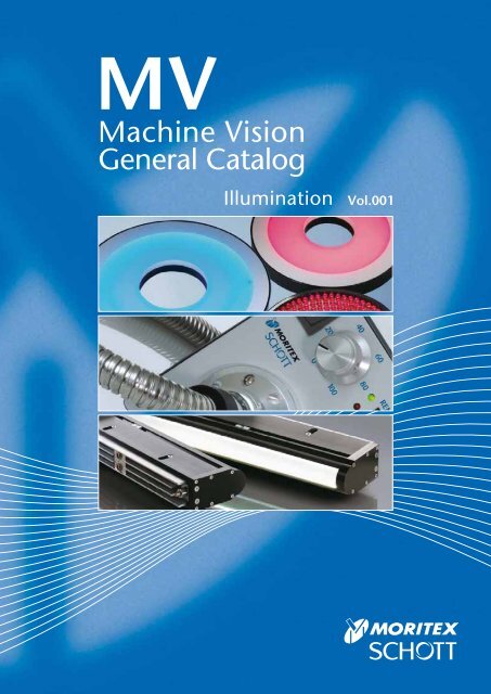
MV<br />
<strong>Machine</strong> <strong>Vision</strong><br />
General <strong>Catalog</strong><br />
<strong>Illumination</strong> <strong>Vol</strong>.<strong>001</strong>
Introduction<br />
Unparalleled Expertise<br />
<strong>Machine</strong> <strong>Vision</strong> Systems combine lighting, imaging, and data<br />
processing to inspect, monitor, and control industrial production<br />
processes. They have been employed in a variety of industries on<br />
a multitude of applications.<br />
As experts in providing Lighting and Imaging solutions for<br />
today’s vast machine vision market, MORITEX and SCHOTT<br />
offer standard and customized solutions for illumination, lens<br />
design, and front end optical systems.<br />
With decades of experience, and extensive know-how, MORITEX<br />
and SCHOTT can provide the total machine vision illumination<br />
and imaging solution designed exclusively for you comprised<br />
from our vast product portfolio.<br />
MORITEX and SCHOTT are leading global suppliers of<br />
illumination and imaging components for machine vision<br />
applications. Our unparalleled expertise in these areas makes<br />
us uniquely qualified to service all different levels from system<br />
design to integrated lighting and imaging system solutions.<br />
Please review the products featured in this catalog and let us<br />
know how we can best serve you!<br />
i-2
Your Global Lighting and Imaging Alliance<br />
Since 2007, MORITEX and SCHOTT have cooperated on a global scale.<br />
Our goal has always been to provide the ultimate products and services to<br />
our customers worldwide. By utilizing the bundled experience and expertise<br />
of these two established companies, we have made this goal a reality.<br />
As an established leader in machine vision systems with an impeccable<br />
track record of innovation, MORITEX is the only provider that can service<br />
all different levels from system design to integrated system solutions.<br />
The SCHOTT Lighting and Imaging division offers a broad range of LED<br />
and fiber optic solutions focusing on illumination, light and image<br />
transmission. In addition, SCHOTT also offers superior hybrid solutions<br />
utilizing the best of LED and fiber optic technologies.<br />
For the first time, MORITEX and SCHOTT present their entire <strong>Machine</strong><br />
<strong>Vision</strong> portfolio together in one catalog at your convenience and reference.<br />
Thank you for taking the time to learn about MORITEX and SCHOTT and<br />
how we can provide you with the ultimate in <strong>Machine</strong> <strong>Vision</strong> solutions.<br />
If you would like more information about any of our products, please don’t<br />
hesitate to contact us.<br />
MORITEX and SCHOTT, Unparalleled Expertise!<br />
i-3
Locations<br />
Spanning the Globe<br />
At MORITEX and SCHOTT we're here to serve you!<br />
With locations spanning more then 40 countries across the globe, we're almost<br />
guaranteed to have an office near you.<br />
This map represents some of our main offices serving the <strong>Machine</strong> <strong>Vision</strong><br />
industry located in Asia, Europe and the USA.<br />
Please don't hesitate to contact us if we can be of service to you. You may refer<br />
to the back cover page for contact information.<br />
San Jose<br />
U.S.A.<br />
Paris<br />
France<br />
Mainz<br />
Germany<br />
Stafford<br />
United Kingdom<br />
Tiel<br />
Netherlands<br />
Yehud<br />
Israel<br />
Tokyo<br />
Japan<br />
Singapore<br />
Shanghai<br />
China<br />
Hong Kong<br />
China<br />
Taipei<br />
Taiwan<br />
i-4
New Products<br />
LED <strong>Illumination</strong><br />
MCV-Light Series<br />
Designed to meet the rigorous needs of industrial<br />
applications, all constant voltage controlled<br />
MCV-Light Series models operate at 24V allowing<br />
for easy connection to available power supplies in<br />
addition to proprietary controllers. This series adds<br />
to the largest and most diverse product offering<br />
available in the industry.<br />
NEW<br />
P.i-10<br />
MG-Wave Series<br />
High Brightness (HB) LED Light Line<br />
SMT<br />
The latest series of SMT HB LED Light Lines provide<br />
extremely high brightness illumination (over 2M lux) while<br />
maintaining high uniformity for challenging line scan<br />
applications in a slim, light-weight design at lengths of up<br />
to 3m. Available in red and white, both the standard &<br />
reflective models have air and water-cooling options.<br />
NEW<br />
P.i-68<br />
LLS2 / MHAA and MHAB Series<br />
LED Light Source<br />
LLS2<br />
NEW<br />
The LLS2 features optimal light output with<br />
parallel 8 bit digital and 0-5V analog control.<br />
This long-life, low power consumption light<br />
source can be used as a drop-in replacement<br />
for the Halogen based MHAA Series models.<br />
P.i-98<br />
i-5
System Flow Chart<br />
LED Controller<br />
for MCV-Light Series<br />
APS<br />
Direct Ring <strong>Illumination</strong><br />
R / SQ<br />
Low Angle Ring <strong>Illumination</strong><br />
RLA / RLA-00<br />
Shadowless <strong>Illumination</strong><br />
FR / DR / DSQ<br />
Bar <strong>Illumination</strong><br />
BA<br />
LED <strong>Illumination</strong> Fiber Optic Light Sources and Light Guides<br />
LED Controller<br />
for MG-Wave Series<br />
MLEK<br />
A080W Analog Series<br />
A080W Digital Series<br />
A230W Analog Series<br />
A230W Digital Series<br />
Multi Channel Series<br />
High Wattage Series<br />
LED Controller<br />
for MCEP/MSPP Series<br />
MLEP<br />
A035W Analog Series<br />
A035W Digital Series<br />
A070W Analog Series<br />
A070W Digital Series<br />
LED Controller<br />
for MLNX Series<br />
MLEX<br />
A600W Digi/Ana<br />
Halogen Light Sources<br />
MHAA / AB<br />
MHAB-IR<br />
LED Light Source<br />
LLS2<br />
LED Light Source<br />
LLS<br />
Halogen Light Source<br />
DCR ® III<br />
DCR ® III Plus<br />
DCR ® IV<br />
Halogen Light Source<br />
ACE ®<br />
Xenon Flash Light Source<br />
MaVi-S<br />
720mm<br />
840mm<br />
Adapter<br />
for MORITEX<br />
Direct Ring <strong>Illumination</strong><br />
MDRL<br />
Low Angle Ring <strong>Illumination</strong><br />
MLRL<br />
Shadowless <strong>Illumination</strong><br />
MSRL / MSLL / MSQL<br />
Bar <strong>Illumination</strong><br />
MBRL<br />
Square Bar Type <strong>Illumination</strong><br />
MDQL<br />
Dome <strong>Illumination</strong><br />
MDML<br />
High Power LED Spot <strong>Illumination</strong><br />
MCEP<br />
LED Spot Projectors<br />
MSPP<br />
High Brightness (HB) LED Light Line<br />
MLNX<br />
Ring Light Guides<br />
MRG/P<br />
Straight Light Guides<br />
MSG/P<br />
Bifurcated Light Guides<br />
MWG/P<br />
Multifurcated Light Guides<br />
M#G#<br />
Plate Type Light Guides<br />
MPP<br />
Line Light Guides<br />
MKG/P<br />
Long Width Line Light Guides<br />
MFKG/P<br />
Universal Ringlight<br />
Midi and Mini Ringlights<br />
Ringlights, 66 mm /58 mm<br />
Darkfield Ringlight<br />
Single Bundles<br />
Dual and Quad Bundles<br />
Randomized and Calibrated Bundles<br />
Single and Dual Goosenecks<br />
Combination Goosenecks & Bundles<br />
Lightlines, 1", 2", & 3"<br />
Lightlines<br />
Spatially Randomized Lightlines<br />
Lightline, 45°<br />
Lightline Lenses<br />
Single and Dual Backlights<br />
PANELite® Backlights<br />
i-6
Square Bar Type <strong>Illumination</strong><br />
BAQ<br />
Simulated Coaxial <strong>Illumination</strong><br />
CX<br />
Direct Backlights (Chip Mount Type)<br />
FL<br />
Options<br />
Simulated Coaxial <strong>Illumination</strong><br />
MSCL<br />
Direct Backlights (Chip Mount Type)<br />
MDBC / MQFC<br />
Direct Backlights (Discrete Type)<br />
MDBL<br />
Edge Type Backlights<br />
MEBL / MEBC<br />
Collimated Backlight <strong>Illumination</strong><br />
MCBP<br />
IR <strong>Illumination</strong><br />
IR<br />
UV <strong>Illumination</strong><br />
UV<br />
Variable Color RGB <strong>Illumination</strong><br />
RGB<br />
Diffuse Chip Type Bar <strong>Illumination</strong><br />
MBRC<br />
Line <strong>Illumination</strong><br />
MLNL<br />
Coaxial <strong>Illumination</strong><br />
MCEC / MCEL<br />
Options<br />
Guidance<br />
LED <strong>Illumination</strong><br />
MCV-Light Series<br />
High Brightness (HB) LED Light Line<br />
SMT<br />
LED <strong>Illumination</strong><br />
MG-Wave Series<br />
Fiber Optic Light Sources and Light Guides<br />
MHAA and MHAB Series<br />
Condenser Lenses<br />
Light Guide Options<br />
Fiber Optic Light Sources and Light Guides<br />
Cold<strong>Vision</strong> Series<br />
Quartz UV Light Guides<br />
Darkfield Illuminator / Ringlight Adapters<br />
Ringlight Polarizers & Analyzers<br />
Diffuse Dome<br />
Ringlight Reflector Rings / Ringlight Support Apparatus<br />
Bundle Extenders<br />
Gooseneck & Bundle Support Apparatus<br />
Support Apparatus<br />
Filters, Diffusers & Spot Lenses<br />
Lightline Linear Polarizer Kits<br />
Lightlines Support Apparatus<br />
Special Application Light Guides<br />
Quartz UV Light Guides<br />
UV<br />
i-7
LED <strong>Illumination</strong><br />
Broad range of lighting solutions<br />
MORITEX and SCHOTT's has the most complete LED illumination portfolio available with<br />
the constant current controlled "MG-Wave Series" and constant voltage controlled<br />
"MCV-Light Series" providing support for the entire range of modern-day users in various<br />
image processing environments.<br />
LED <strong>Illumination</strong><br />
Image processing total system solutions support<br />
Our total system solutions approach provides customers with the best performance & efficiency<br />
through consideration of the 3 essential imaging fields of illumination, lens, and peripherals.<br />
Selection of LED <strong>Illumination</strong><br />
Making obscure and unrecognizable images<br />
become sharp and clear<br />
Our total system solutions meet a wide range of needs for image processing applications.<br />
MCV-Light Series<br />
NEW<br />
Constant <strong>Vol</strong>tage Control System / 24V DC /<br />
Industrial Design with Metal Connectors<br />
The MCV-Light Series constant voltage control LED illumination<br />
products are 24V DC driven and can be controlled by<br />
proprietary APS LED controllers as well as other available<br />
industrial 24V power supplies. Over-driven strobing is also<br />
possible for instantaneous, high intensity illumination. This<br />
series can be used in various machine vision imaging<br />
environments providing a broad range of lighting solutions.<br />
MG-Wave Series<br />
Constant Current Control System /<br />
Extensive Product Variety /<br />
Unique, High End Solutions<br />
The MG-Wave Series is our original LED illumination product<br />
line designed with our patented highly sophisticated integrated<br />
constant current sensing control system that enables our LED<br />
controllers to identify the appropriate current value for each<br />
individual LED unit connected and control them separately. The<br />
constant current design successfully reduces heat generation to<br />
improve output intensity, efficiency, and stability.<br />
i-8
Selection flowchart<br />
Identify<br />
object<br />
& FOV<br />
Select camera,<br />
lens, and<br />
peripherals<br />
Choose LED<br />
configuration,<br />
type, and<br />
wavelength<br />
Choose LED<br />
controller<br />
(i.e. drive method)<br />
Test system<br />
for proof<br />
of concept<br />
Complete<br />
setup<br />
*Refer to <strong>Machine</strong> <strong>Vision</strong><br />
General <strong>Catalog</strong> “Lens”<br />
MCV-Light<br />
MG-Wave<br />
LED Lineup Reference Table<br />
<strong>Illumination</strong> Type<br />
Direct Ring <strong>Illumination</strong><br />
Low Angle Ring <strong>Illumination</strong><br />
Shadowless <strong>Illumination</strong><br />
Bar <strong>Illumination</strong><br />
Square Bar Type <strong>Illumination</strong><br />
Dome <strong>Illumination</strong><br />
Simulated Coaxial <strong>Illumination</strong><br />
Direct Backlighting (Chip Mount Type)<br />
Direct Backlighting (Discrete Type)<br />
Edge Type Backlighting<br />
Collimated Backlight <strong>Illumination</strong><br />
High Brightness LED Light Line<br />
Line <strong>Illumination</strong><br />
Diffuse Chip Type Bar <strong>Illumination</strong><br />
High Power LED Spot <strong>Illumination</strong><br />
Coaxial <strong>Illumination</strong><br />
LED Spot Projector<br />
IR <strong>Illumination</strong><br />
UV <strong>Illumination</strong><br />
Variable Color RGB <strong>Illumination</strong><br />
24V DC Driven<br />
Controlled by proprietary APS LED controllers<br />
as well as other available industrial 24V power<br />
suppliers. Over-driven strobing and branched<br />
connection also available.<br />
Extensive Product Variety<br />
More than 350 models with low heat<br />
generation and high luminance efficiency<br />
MCV-Light Sereis<br />
R<br />
SQ<br />
RLA<br />
RLA-00<br />
FR<br />
DR<br />
DSQ<br />
BA<br />
BAQ<br />
CX<br />
FL<br />
MG-Wave Series<br />
MDRL<br />
MLRL<br />
MSRL<br />
MSLL<br />
MSQL<br />
MBRL<br />
MDQL<br />
MDML<br />
MSCL<br />
MDBC<br />
MQFC<br />
MDBL<br />
MEBL<br />
MEBC<br />
MCBP<br />
MLNX<br />
SMT<br />
MLNL<br />
MBRC<br />
MCEP<br />
MCEC<br />
MCEL<br />
MSPP<br />
IR<br />
UV<br />
RGB<br />
24V DC Input<br />
DIN Rail Mountable<br />
Analog 2-channel LED controller<br />
without external control<br />
100-240V AC Input Analog & Digital<br />
Controllers with External Control<br />
Input<br />
Channel<br />
External<br />
Control<br />
1-ch, 2-ch, & 4-ch models available;<br />
3-ch available for MCEP Series<br />
MCV-Light<br />
MG-Wave<br />
MCV-Light<br />
MG-Wave<br />
MCV-Light<br />
MG-Wave<br />
DC24V<br />
AC100V~240V<br />
2ch<br />
1ch, 2ch, 4ch<br />
N/A<br />
Analog (0-5V)<br />
Digital (Pararell/8bit)<br />
LED Controller Lineup Reference<br />
Analog LED Controllers<br />
for MCV-Light Series<br />
24V DC, DIN rail mountable<br />
LED Controllers<br />
for MG-Wave Series<br />
Constant current sensing<br />
control system<br />
LED Controllers<br />
for MCEP/MSPP Series<br />
For high power LED spot<br />
illumination<br />
LED <strong>Illumination</strong><br />
Selection of LED <strong>Illumination</strong><br />
LED Controllers<br />
for MLNX Series<br />
Applicable lighting length:<br />
840-2880mm<br />
i-9
LED <strong>Illumination</strong><br />
LED <strong>Illumination</strong><br />
MC V- Light Series<br />
24V DC Driven / Industrial Design with Metal Connectors<br />
MCV-Light Series<br />
MCV-Light Series employs the constant voltage control system that can be<br />
controlled not only by APS LED controllers but also by industry available 24V<br />
DC power supplies directly. Overdriven strobing for instantaneous high intensity<br />
illumination is also available. The series can support customer’s various image<br />
processing environments with a broad range of lighting solutions.<br />
LED Controller<br />
for MCV-Light Series<br />
APS<br />
Direct Ring <strong>Illumination</strong><br />
R / SQ<br />
Low Angle Ring <strong>Illumination</strong><br />
RLA / RLA-00<br />
Shadowless <strong>Illumination</strong><br />
FR / DR / DSQ<br />
Bar <strong>Illumination</strong><br />
BA<br />
Square Bar Type <strong>Illumination</strong><br />
BAQ<br />
Simulated Coaxial <strong>Illumination</strong><br />
CX<br />
Direct Backlights (Chip Mount Type)<br />
FL<br />
Options<br />
i-10
LED <strong>Illumination</strong><br />
MC V- Light Series<br />
LED SAFETY STANDARD (CEI/IEC 62471:2006)<br />
Groups<br />
Exempt<br />
Definition and Emission limit<br />
Not more than 1.0 W·m -2 . Small source<br />
defined as one with
LED <strong>Illumination</strong><br />
MCV-Light Series<br />
Direct Ring <strong>Illumination</strong><br />
R/SQ Series<br />
RoHS<br />
CE<br />
Direct Ring <strong>Illumination</strong><br />
R Series<br />
SQ Series<br />
R / SQ<br />
Direct Ring <strong>Illumination</strong>: R Series<br />
• High intensity, uniform direct, bright-field 360-degree lighting<br />
Explanation of Model Code<br />
R - X -<br />
• Standard LED illumination for a wide range of applications<br />
External<br />
Diameter<br />
Internal<br />
Diameter<br />
Lighting<br />
Angle<br />
Emitted<br />
Color<br />
Square Ring <strong>Illumination</strong>: SQ Series<br />
• Ring illumination with LEDs mounted vertically onto a planar<br />
substrate in a square chassis<br />
SQ - X X<br />
External Dimensions<br />
Length<br />
Width<br />
Internal<br />
Diameter<br />
Emitted<br />
Color<br />
Lineup of Direct Ring Type LEDs<br />
Model<br />
Emitted<br />
Color<br />
Power<br />
(W)<br />
Lineup of Square Ring Type LEDs<br />
Internal External<br />
Lighting<br />
Diameter Diameter<br />
Angle<br />
(mm) (mm)<br />
Weight<br />
(g)<br />
Product<br />
Code<br />
R-32X10-70R Red 1.5 32 10 70˚ 50 A-2600<br />
R-32X10-70B Blue 2.1 32 10 70˚ 50 A-2602<br />
R-32X10-70W White 2.1 32 10 70˚ 50 A-2601<br />
R-42X18-65R Red 1.8 42 18 65˚ 75 A-2603<br />
R-42X18-65B Blue 2.8 42 18 65˚ 75 A-2605<br />
R-42X18-65W White 2.8 42 18 65˚ 75 A-2604<br />
R-50X28-75R Red 2.1 50 28 75˚ 75 A-2606<br />
R-50X28-75B Blue 3.6 50 28 75˚ 75 A-2608<br />
CCD<br />
R-50X28-75W White 3.6 50 28 75˚ 75 A-2607<br />
R-70X35-90R Red 4.2 70 35 90˚ 150 A-2609<br />
R-70X35-90B Blue 6.6 70 35 90˚ 150 A-2611<br />
R-70X35-90W White 6.6 70 35 90˚ 150 A-2610<br />
R-90X30-80R Red 8.1 90 30 83˚ 250 A-2612<br />
R-90X30-80B Blue 9.6 90 30 83˚ 250 A-2614<br />
R-90X30-80W White 9.6 90 30 83˚ 250 A-2613<br />
R-90X50-70R Red 6.1 90 50 71˚ 200 A-2615<br />
R-90X50-70B Blue 8.3 90 50 71˚ 200 A-2617<br />
R-90X50-70W White 8.3 90 50 71˚ 200 A-2616<br />
<br />
R-120X60-50R Red 8.4 120 60 52˚ 550 A-2618<br />
R-120X60-50B Blue 17 120 60 52˚ 550 A-2620<br />
R-120X60-50W White 17 120 60 52˚ 550 A-2619<br />
Model<br />
Emitted<br />
Color<br />
Power<br />
(W)<br />
External Dimensions (mm)<br />
Length<br />
Width<br />
Internal Weight Product<br />
Diameter (g) Code<br />
SQ-56X56X30R Red 2.1 56 56 30 100 A-2776<br />
SQ-56X56X30B Blue 3.3 56 56 30 100 A-2778<br />
SQ-56X56X30W White 3.3 56 56 30 100 A-2777<br />
<br />
<strong>Illumination</strong> Structure<br />
R Series<br />
SQ Series<br />
CCD Camera <br />
Lens<br />
Lens<br />
Object<br />
<br />
Object<br />
i-12
R-32X10-70R (B,W)<br />
R-42X18-65R (B,W)<br />
ø10<br />
4-M3x4mm Depth PCD 20<br />
Equidistribution<br />
4-M3 4 PCD20<br />
ø18<br />
4-M3x4mm Depth PCD 28<br />
Equidistribution<br />
4-M3 4 PCD28<br />
45<br />
45<br />
16<br />
ø32 500<br />
70<br />
(3.1)<br />
(ø4)<br />
(60)<br />
(20)<br />
(46.8)<br />
(ø15.3)<br />
CN1<br />
4<br />
1 3<br />
2<br />
18<br />
ø42<br />
65<br />
(3.1)<br />
(ø4)<br />
500 (46.8)<br />
(60)<br />
(20)<br />
(ø15.3)<br />
CN1<br />
4<br />
1 3<br />
2<br />
R-50X28-75R (B,W)<br />
R-70X35-90R (B,W)<br />
ø28<br />
4-M3x4mm Depth PCD 40<br />
Equidistribution<br />
4-M3 4 PCD40<br />
ø35 4-M3x4mm Depth PCD 50<br />
Equidistribution<br />
4-M3 4 PCD50<br />
16<br />
ø50<br />
75<br />
45<br />
(3.1)<br />
R-90X30-80R (B,W)<br />
(ø4)<br />
500<br />
(60)<br />
(20)<br />
ø30 4-M3x4mm Depth PCD 70<br />
Equidistribution<br />
4-M3 4 PCD70<br />
(46.8)<br />
(ø15.3)<br />
CN1<br />
4<br />
1 3<br />
2<br />
ø70<br />
22<br />
(6)<br />
(ø4)<br />
500<br />
(60)<br />
R-90X50-70R (B,W)<br />
45<br />
(20)<br />
ø50 4-M3x4mm Depth PCD 70<br />
Equidistribution<br />
4-M3 4 PCD70<br />
(46.8)<br />
(ø15.3)<br />
CN1<br />
4<br />
1 3<br />
2<br />
Direct Ring <strong>Illumination</strong><br />
20<br />
83<br />
ø90<br />
45<br />
(3.1)<br />
(ø4)<br />
500 (46.8)<br />
(60)<br />
(20)<br />
(ø15.3)<br />
CN1<br />
4<br />
1 3<br />
2<br />
20<br />
71<br />
ø90<br />
45<br />
(3.1)<br />
(ø4)<br />
500 (46.8)<br />
(60)<br />
(20)<br />
(15.3)<br />
CN1<br />
4<br />
1 3<br />
2<br />
R / SQ<br />
R-120X60-50R (B,W)<br />
SQ-56X56X30R (B,W)<br />
ø60<br />
4-M3x4mm Depth PCD 90<br />
Equidistribution<br />
4-M3 4 PCD90<br />
38<br />
ø30<br />
4-M3x3mm Tap Depth<br />
4-M3 3<br />
56<br />
38<br />
45<br />
31.5<br />
52<br />
ø120<br />
(15.6)<br />
(ø4)<br />
500<br />
(60)<br />
(20)<br />
(46.8)<br />
(ø15.3)<br />
CN1<br />
4<br />
1 3<br />
2<br />
18<br />
56 500 (46.8)<br />
(4)<br />
(ø4)<br />
(60)<br />
46<br />
(20)<br />
(ø15.3)<br />
CN1<br />
4<br />
1 3<br />
2<br />
4-M2x3mm Tap Depth<br />
4-M2 3<br />
46<br />
Relative Intensity<br />
Relative Intensity<br />
1.0<br />
0.8<br />
0.6<br />
0.4<br />
0.2<br />
Light Distribution Characteristics<br />
R-42X18-65W<br />
R-70X35-90W<br />
R-90X50-70W<br />
1.2<br />
1.2<br />
Relative Intensity<br />
0.0<br />
0.0<br />
-60 -40 -20 0 20 40 60 -150 -100 -50 0 50 100 150<br />
Distance From Center (X-Axis) (mm)<br />
Distance From Center (X-Axis) (mm)<br />
WD=5 WD=10 WD=20 WD=30 WD=40<br />
WD=35 WD=45 WD=60 WD=80 WD=100<br />
SQ-56X56X30W<br />
1.2<br />
1.0<br />
0.8<br />
0.6<br />
0.4<br />
0.2<br />
0.0<br />
-100 -80 -60 -40 -20 0 20 40 60 80 100<br />
Distance From Center (X-Axis) (mm)<br />
WD=25 WD=35 WD=50 WD=65 WD=80<br />
1.0<br />
0.8<br />
0.6<br />
0.4<br />
0.2<br />
Relative Intensity<br />
1.2<br />
1.0<br />
0.8<br />
0.6<br />
0.4<br />
0.2<br />
0.0<br />
-150 -100 -50 0 50 100 150<br />
Distance From Center (X-Axis) (mm)<br />
WD=25 WD=35 WD=45 WD=60 WD=80<br />
i-13
LED <strong>Illumination</strong><br />
MCV-Light Series<br />
R Series<br />
Sample Images<br />
Foreign Object in Paper Cup<br />
PCB Fabrication Inspection<br />
Direct Ring <strong>Illumination</strong><br />
SQ Series<br />
Not Much Light at Short WD<br />
Full Light at Longer WD<br />
R / SQ<br />
Accessories<br />
Adapter Diffuser Polarizer Method of Mounting<br />
AD-Rxx<br />
R Series<br />
Used to mount<br />
the diffuser or<br />
polarizer onto the<br />
LED lighting.<br />
DF-Rxx<br />
DF-SQxx<br />
To be mounted in front of<br />
the LED lighting using the<br />
adapter. Used to soften<br />
the lighting output, so<br />
as to reduce the glare on<br />
specular surface.<br />
PL-Rxx<br />
PL-SQxx<br />
To be mounted in front of<br />
the LED lighting using the<br />
adapter. Use together with<br />
second polarizer(analyzer)<br />
to help reduce glare.<br />
LED <strong>Illumination</strong><br />
Diffuser/Polarizer<br />
Adapter<br />
The adapter is used to hold the diffuser/<br />
polarizer to the LED lighting.<br />
SQ Series<br />
Model Product Type Compatible Light Models Product Code<br />
AD-R32X10 Adapter R-32x10-70R/B/W A-2812<br />
DF-R32X10 Diffuser R-32x10-70 A-2813<br />
PL-R32X10 Polarizer R-32x10-70 A-2814<br />
AD-R42X18 Adapter R-42x18-65 A-2815<br />
DF-R42X18 Diffuser R-42x18-65 A-2816<br />
PL-R42X18 Polarizer R-42x18-65 A-2817<br />
AD-R50X28 Adapter R-50x28-75 A-2818<br />
DF-R50X28 Diffuser R-50x28-75 A-2819<br />
PL-R50X28 Polarizer R-50x28-75 A-2820<br />
AD-R70X35 Adapter R-70x35-90 A-2821<br />
DF-R70X35 Diffuser R-70x35-90 A-2822<br />
PL-R70X35 Polarizer R-70x35-90 A-2823<br />
AD-R90X50 Adapter R-90x50-70 A-2824<br />
DF-R90X50 Diffuser R-90x50-70 A-2825<br />
PL-R90X50 Polarizer R-90x50-70 A-2826<br />
AD-R120X60 Adapter R-120x60-50 A-2827<br />
DF-R120X60 Diffuser R-120x60-50 A-2828<br />
PL-R120X60 Polarizer R-120x60-50 A-2829<br />
DF-SQ56X56X30 Diffuser SQ-56x56x30 A-2858<br />
PL-SQ56X56X30 Polarizer SQ-56x56x30 A-2859<br />
Screws<br />
The given screws are used<br />
to hold the diffuser/polarizer<br />
to the LED lighting.<br />
LED<br />
<strong>Illumination</strong><br />
Diffuser/<br />
Polarizer<br />
i-14
Low Angle Ring <strong>Illumination</strong><br />
RLA/RLA-00 Series<br />
RoHS<br />
CE<br />
RLA Series<br />
RLA-00 Series<br />
Low Angle Ring <strong>Illumination</strong><br />
Low Angle Ring <strong>Illumination</strong>: RLA Series<br />
• Reflection can be minimized by the low-angle, dark-field lighting<br />
configuration<br />
• Ideal for imaging of uneven surfaces, eg. embossment and<br />
surface flaw detection<br />
Explanation of Model Code<br />
RLA - X -<br />
External<br />
Diameter<br />
Internal<br />
Diameter<br />
Lighting<br />
Angle<br />
Emitted<br />
Color<br />
RL A / RL A - 0 0<br />
Zero Angle Ring <strong>Illumination</strong>: RLA-00 Series<br />
• Indirect, horizontal 360-degree inner diameter illumination<br />
• Used at a short WD to the test object<br />
Lineup of Low Angle Ring Type LEDs<br />
Model<br />
Emitted<br />
Color<br />
Power<br />
(W)<br />
Internal<br />
Diameter<br />
(mm)<br />
External<br />
Lighting Weight<br />
Diameter<br />
Angle (g)<br />
(mm)<br />
Product<br />
Code<br />
RLA-74X48-30R Red 4.0 74 48 30˚ 120 A-2631<br />
RLA-74X48-30B Blue 5.4 74 48 30˚ 120 A-2633<br />
RLA-74X48-30W White 5.4 74 48 30˚ 120 A-2632<br />
RLA-100X70-30R Red 6.3 100 70 30˚ 190 A-2634<br />
RLA-100X70-30B Blue 9.8 100 70 30˚ 190 A-2636<br />
RLA-100X70-30W White 9.8 100 70 30˚ 190 A-2635<br />
RLA-132X96-15R Red 7.7 132 96 15˚ 300 A-2637<br />
RLA-132X96-15B Blue 14 132 96 15˚ 300 A-2639<br />
RLA-132X96-15W White 14 132 96 15˚ 300 A-2638<br />
Lineup of Zero Angle Ring Type LEDs<br />
Model<br />
Emitted<br />
Color<br />
Power<br />
(W)<br />
Internal<br />
Diameter<br />
(mm)<br />
External<br />
Lighting Weight Product<br />
Diameter<br />
Angle (g) Code<br />
(mm)<br />
RLA-75X46-00R Red 1.7 75 46 0˚ 95 A-2640<br />
RLA-75X46-00B Blue 3.3 75 46 0˚ 95 A-2642<br />
RLA-75X46-00W White 3.3 75 46 0˚ 95 A-2641<br />
RLA-96X60-00R Red 2.1 96 60 0˚ 140 A-2643<br />
RLA-96X60-00B Blue 4.2 96 60 0˚ 140 A-2645<br />
RLA-96X60-00W White 4.2 96 60 0˚ 140 A-2644<br />
<strong>Illumination</strong> Structure<br />
RLA Series<br />
CCD Camera<br />
Object<br />
Lens<br />
Illuminating the Object<br />
from a Low Position<br />
RLA-00 Series<br />
CCD Camera<br />
Object<br />
Lens<br />
i-15
LED <strong>Illumination</strong><br />
MCV-Light Series<br />
RLA-74X48-30R (B,W)<br />
RLA-100X70-30R (B,W)<br />
ø48<br />
4-M3x4mm Depth PCD 60<br />
Equidistribution<br />
4-M3 4 PCD60<br />
ø70<br />
4-M3x4mm Depth PCD 84<br />
Equidistribution<br />
4-M3 4 PCD84<br />
45<br />
Low Angle Ring <strong>Illumination</strong><br />
ø74<br />
500 (46.8)<br />
19<br />
(3.1)<br />
(ø4)<br />
(20)<br />
30<br />
(60)<br />
RLA-132X96-15R (B,W)<br />
3-M3x4mm Depth PCD 116<br />
Equidistribution<br />
ø96<br />
3-M3 4 PCD116<br />
45<br />
(ø15.3)<br />
CN1<br />
4<br />
1 3<br />
2<br />
22<br />
30<br />
45<br />
ø100 500<br />
(3.1)<br />
(ø4)<br />
(60)<br />
(20)<br />
(46.8)<br />
(ø15.3)<br />
CN1<br />
4<br />
1 3<br />
2<br />
RL A / RL A - 0 0<br />
22<br />
15<br />
ø132 500 (46.8)<br />
(3.1)<br />
(ø4)<br />
(20)<br />
(60)<br />
RLA-75X46-00R (B,W)<br />
(15.3)<br />
CN1<br />
4<br />
1 3<br />
2<br />
RLA-96X60-00R (B,W)<br />
ø46<br />
4-M3x4mm Depth PCD 56<br />
Equidistribution<br />
ø60<br />
4-M3x4mm Depth PCD80<br />
Equidistribution<br />
4-M3 4 PCD80<br />
4-M3 4 PCD56<br />
45<br />
10<br />
ø75<br />
(3.5)<br />
(ø4)<br />
500<br />
(20)<br />
(46.8)<br />
(ø15.3)<br />
CN1<br />
4<br />
1 3<br />
ø96 500 (46.8)<br />
(3.5)<br />
(ø4)<br />
(20)<br />
(ø15.3)<br />
CN1<br />
4<br />
(60)<br />
2<br />
10<br />
(60)<br />
1 3<br />
2<br />
Relative Intensity<br />
1.2<br />
1.0<br />
0.8<br />
0.6<br />
0.4<br />
0.2<br />
RLA-74X48-30W<br />
0.0<br />
-80 -60 -40 -20 0 20 40 60 80<br />
Distance From Center (X-Axis) (mm)<br />
Light Distribution Characteristics<br />
Relative Intensity<br />
1.2<br />
1.0<br />
0.8<br />
0.6<br />
0.4<br />
0.2<br />
RLA-100X70-30W<br />
0.0<br />
-100 -80 -60 -40 -20 0 20 40 60 80 100<br />
Distance From Center (X-Axis) (mm)<br />
Relative Intensity<br />
1.2<br />
1.0<br />
0.8<br />
0.6<br />
0.4<br />
0.2<br />
RLA-132X96-15W<br />
0.0<br />
-150 -100 -50 0 50 100 150<br />
Distance From Center (X-Axis) (mm)<br />
WD=5 WD=15 WD=25 WD=35 WD=40<br />
WD=5 WD=10 WD=20 WD=25 WD=30 WD=5 WD=15 WD=25 WD=30 WD=35<br />
Relative Intensity<br />
1.2<br />
1.0<br />
0.8<br />
0.6<br />
0.4<br />
0.2<br />
RLA-75X46-00W<br />
0.0<br />
-60 -40 -20 0 20 40 60<br />
Distance From Center (X-Axis) (mm)<br />
WD=5 WD=10 WD=15 WD=20 WD=25<br />
Relative Intensity<br />
1.2<br />
1.0<br />
0.8<br />
0.6<br />
0.4<br />
0.2<br />
RLA-96X60-00W<br />
0.0<br />
-80 -60 -40 -20 0 20 40 60 80<br />
Distance From Center (X-Axis) (mm)<br />
WD=5 WD=10 WD=15 WD=20 WD=25<br />
i-16
RLA Series<br />
Sample Images<br />
Chamfer Checking on Metal Ring<br />
RLA-00 Series<br />
Scratch on Glass Plate<br />
12-Pin Connector<br />
CD Imprint Inspection<br />
Low Angle Ring <strong>Illumination</strong><br />
Accessories<br />
RL A / RL A - 0 0<br />
Diffuser Ring<br />
Method of Mounting<br />
DF-RLAxxx<br />
Used to create a relatively non-directional<br />
light. Reduces glare on specular surfaces.<br />
Easily mount onto Low-Angle Ring light.<br />
Diffuser<br />
Set Screws<br />
LED <strong>Illumination</strong><br />
The diffuser is mounted to the inner side of the<br />
Low-Angle Ring Light by three set screws.<br />
Model Product Type Compatible Light Models Product Code<br />
DF-RLA74X48 Diffuser Ring RLA-74x48-30 A-2830<br />
DF-RLA100X70 Diffuser Ring RLA-100x70-30 A-2831<br />
DF-RLA132X96 Diffuser Ring RLA-132x96-15 A-2832<br />
i-17
LED <strong>Illumination</strong><br />
MCV-Light Series<br />
Shadowless <strong>Illumination</strong><br />
FR/DR/DSQ Series<br />
RoHS<br />
CE<br />
Shadowless <strong>Illumination</strong><br />
DR Series<br />
FR Series<br />
FR / DR / DSQ<br />
Shadowless Ring <strong>Illumination</strong>: FR Series<br />
• Diffuse, shadowless illumination* Optimal soft, uniform light<br />
for shiny surfaces<br />
Explanation of Model Code<br />
FR -<br />
DSQ Series<br />
External<br />
Diameter<br />
X<br />
Internal<br />
Diameter<br />
Emitted<br />
Color<br />
Shadowless Low Angle Ring <strong>Illumination</strong>: DR Series<br />
DR -<br />
X<br />
• Shallow angle LED illumination that provides diffused, soft light<br />
• Ideal for flaw or edge detection on reflective surfaces<br />
External<br />
Diameter<br />
Internal<br />
Diameter<br />
Emitted<br />
Color<br />
Square Shadowless Low Angle <strong>Illumination</strong>: DSQ Series<br />
• Diffused illumination best suited for square shape objects, such<br />
as in BGA & QFP applications<br />
DSQ - X -<br />
External Dimensions<br />
Length<br />
Width<br />
Height of<br />
Lighting Surface<br />
Emitted<br />
Color<br />
<strong>Illumination</strong> Structure<br />
FR Series<br />
DR Series<br />
DSQ Series<br />
<br />
CCD<br />
Camera<br />
CCD CCD Camera<br />
CCD Camera<br />
<br />
<br />
Lens<br />
Lens <br />
Lens<br />
<br />
Object <br />
Object<br />
Object<br />
i-18
Lineup of Shadowless Ring Type LEDs<br />
Model<br />
Emitted<br />
Color<br />
Power<br />
(W)<br />
Internal<br />
Diameter<br />
(mm)<br />
External<br />
Diameter<br />
(mm)<br />
Weight<br />
(g)<br />
Product<br />
Code<br />
FR-102X33R Red 2.5 102 33 210 A-2656<br />
FR-102X33B Blue 5.1 102 33 210 A-2658<br />
FR-102X33W White 5.1 102 33 210 A-2657<br />
FR-125X44R Red 4.3 125 44 290 A-2659<br />
FR-125X44B Blue 6.3 125 44 290 A-2661<br />
FR-125X44W White 6.3 125 44 290 A-2660<br />
Lineup of Shadowless, Low Angle Ring Type LEDs<br />
Model<br />
Emitted<br />
Color<br />
Power<br />
(W)<br />
Internal<br />
Diameter<br />
(mm)<br />
External<br />
Diameter<br />
(mm)<br />
Weight<br />
(g)<br />
Product<br />
Code<br />
DR-100X73R Red 4.2 100 73 260 A-2672<br />
DR-100X73B Blue 8.4 100 73 260 A-2674<br />
DR-100X73W White 8.4 100 73 260 A-2673<br />
DR-136X109R Red 6.3 136 109 340 A-2675<br />
DR-136X109B Blue 13 136 109 340 A-2677<br />
DR-136X109W White 13 136 109 340 A-2676<br />
DR-180X153R Red 8.3 180 153 450 A-2678<br />
DR-180X153B Blue 17 180 153 450 A-2680<br />
DR-180X153W White 17 180 153 450 A-2679<br />
Lineup of Shadowless, Low Angle Square Type LEDs<br />
Model<br />
Emitted<br />
Color<br />
Power<br />
(W)<br />
External Dimensions<br />
(mm)<br />
Length<br />
Width<br />
Height of Lighting<br />
Surface<br />
(mm)<br />
Weight<br />
(g)<br />
Product<br />
Code<br />
DSQ-48X48-15R Red 1.3 48 48 15 130 A-2789<br />
DSQ-48X48-15B Blue 2.6 48 48 15 130 A-2791<br />
DSQ-48X48-15W White 2.6 48 48 15 130 A-2790<br />
DSQ-75X75-15R Red 1.7 75 75 15 200 A-2792<br />
DSQ-75X75-15B Blue 3.4 75 75 15 200 A-2794<br />
DSQ-75X75-15W White 3.4 75 75 15 200 A-2793<br />
DSQ-96X96-15R Red 2.5 96 96 15 220 A-2795<br />
DSQ-96X96-15B Blue 5.1 96 96 15 220 A-2797<br />
DSQ-96X96-15W White 5.1 96 96 15 220 A-2796<br />
DSQ-120X120-15R Red 3.4 120 120 15 260 A-2798<br />
DSQ-120X120-15B Blue 6.7 120 120 15 260 A-2800<br />
DSQ-120X120-15W White 6.7 120 120 15 260 A-2799<br />
Shadowless <strong>Illumination</strong><br />
FR / DR / DSQ<br />
i-19
LED <strong>Illumination</strong><br />
MCV-Light Series<br />
FR-102X33R (B,W)<br />
FR-125X44R (B,W)<br />
12<br />
ø102 500<br />
(9)<br />
(ø4)<br />
(20)<br />
(46.8)<br />
(ø15.3)<br />
CN1<br />
4<br />
1 3<br />
12<br />
ø125 500<br />
(9)<br />
(ø4)<br />
(20)<br />
(46.8)<br />
(ø15.3)<br />
CN1<br />
4<br />
1 3<br />
ø80(Lighting Surface)<br />
ø33<br />
(60)<br />
2<br />
ø103(Lighting Surface)<br />
ø44<br />
(60)<br />
2<br />
Shadowless <strong>Illumination</strong><br />
FR / DR / DSQ<br />
40<br />
DR-100X73R (B,W)<br />
ø73<br />
ø100<br />
ø93.5(Lighting Surface)<br />
3-M3x4mm Tap Depth on the Back<br />
PCD 70 Equidistribution<br />
3-M3 4 PCD70<br />
4-M3x4mm Depth PCD 84<br />
Equidistribution<br />
4-M3 4 PCD84<br />
500<br />
(7.5)<br />
(ø4)<br />
(20)<br />
DR-180X153R (B,W)<br />
(60)<br />
ø153<br />
4-M3x4mm Depth PCD 164<br />
Equidistribution<br />
(46.8)<br />
(ø15.3)<br />
CN1<br />
4<br />
1 3<br />
2<br />
40<br />
DR-136X109R (B,W)<br />
ø109<br />
ø136<br />
ø129.5(Lighting Surface)<br />
3-M3x4mm Tap Depth on the Back<br />
PCD 70 Equidistribution<br />
3-M3 4 PCD70<br />
4-M3x4mm Depth PCD 120<br />
Equidistribution<br />
4-M3 4 PCD120<br />
(7.5)<br />
(ø4)<br />
500<br />
(60)<br />
(20)<br />
(46.8)<br />
(ø15.3)<br />
CN1<br />
4<br />
1 3<br />
2<br />
4-M3 4 PCD164<br />
ø180<br />
(7.5)<br />
(ø4)<br />
500<br />
(20)<br />
(46.8)<br />
(ø15.3)<br />
CN1<br />
4<br />
40<br />
(60)<br />
1 3<br />
2<br />
ø173.5(Lighting Surface)<br />
DSQ-48X48-15R (B,W)<br />
DSQ-75X75-15R (B,W)<br />
30<br />
26<br />
10<br />
4-M3x3mm Tap Depth<br />
57<br />
53<br />
20<br />
4-M3x3mm Tap Depth<br />
4-M3 3<br />
4-M3 3<br />
75<br />
57<br />
53<br />
20<br />
48<br />
30<br />
26<br />
10<br />
48 500 (46.8)<br />
(ø15.3)<br />
CN1<br />
4<br />
30<br />
15(Lighting Surface)<br />
36<br />
(Lighting Surface)<br />
(4)<br />
(ø4)<br />
(60)<br />
(20)<br />
1 3<br />
2<br />
30<br />
15(Lighting Surface)<br />
75<br />
63<br />
(Lighting Surface)<br />
(4)<br />
(ø4)<br />
500 (46.8)<br />
(60)<br />
(20)<br />
(15.3)<br />
CN1<br />
4<br />
1 3<br />
2<br />
DSQ-96X96-15R (B,W)<br />
DSQ-120X120-15R (B,W)<br />
78<br />
74<br />
4-M3x3mm Tap Depth<br />
4-M3 3<br />
102<br />
98<br />
4-M3x3mm Tap Depth<br />
4-M3 3<br />
30<br />
15(Lighting Surface)<br />
96<br />
78<br />
74<br />
120<br />
102<br />
98<br />
96 500 (46.8)<br />
84<br />
(Lighting Surface)<br />
(4)<br />
(ø4)<br />
(20)<br />
(60)<br />
(ø15.3)<br />
CN1<br />
4<br />
1 3<br />
2<br />
30<br />
15(Lighting Surface)<br />
120 500 (46.8)<br />
108<br />
(Lighting Surface)<br />
(4)<br />
(ø4)<br />
(20)<br />
(60)<br />
(ø15.3)<br />
CN1<br />
4<br />
1 3<br />
2<br />
i-20
Relative Intensity<br />
1.2<br />
1.0<br />
0.8<br />
0.6<br />
0.4<br />
0.2<br />
Light Distribution Characteristics<br />
FR-102X33W<br />
FR-125X44W<br />
0.0<br />
-150 -100 -50 0 50 100 200<br />
Distance From Center (X-Axis) (mm)<br />
WD=20 WD=25 WD=30 WD=40 WD=50<br />
Relative Intensity<br />
1.2<br />
1.0<br />
0.8<br />
0.6<br />
0.4<br />
0.2<br />
0.0<br />
-200 -150 -100 -50 0 50 100 150 200<br />
Distance From Center (X-Axis) (mm)<br />
WD=35 WD=40 WD=50 WD=60 WD=80<br />
Relative Intensity<br />
1.2<br />
1.0<br />
0.8<br />
0.6<br />
0.4<br />
0.2<br />
DR100X73W<br />
0.0<br />
-100 -80 -60 -40 -20 0 20 40 60 80 100<br />
Distance From Center (X-Axis) (mm)<br />
WD=25 WD=35 WD=45 WD=60 WD=80<br />
Relative Intensity<br />
1.2<br />
1.0<br />
0.8<br />
0.6<br />
0.4<br />
0.2<br />
DR-136X109W<br />
0.0<br />
-200 -150 -100 -50 0 50 100 150 200<br />
Distance From Center (X-Axis) (mm)<br />
WD=40 WD=50 WD=60 WD=80 WD=100<br />
Relative Intensity<br />
1.2<br />
1.0<br />
0.8<br />
0.6<br />
0.4<br />
0.2<br />
DR-180X153W<br />
0.0<br />
-300 -200 -100 0 100 200 300<br />
Distance From Center (X-Axis) (mm)<br />
WD=50 WD=60 WD=80 WD=100 WD=120<br />
Shadowless <strong>Illumination</strong><br />
Relative Intensity<br />
DSQ-48X48-15W<br />
DSQ-75X75-15W<br />
DSQ-120X120-15W<br />
1.2<br />
1.0<br />
0.8<br />
0.6<br />
0.4<br />
0.2<br />
0.0<br />
-80 -60 -40 -20 0 20 40 60 80<br />
Distance From Center (X-Axis) (mm)<br />
Relative Intensity<br />
1.2<br />
1.0<br />
0.8<br />
0.6<br />
0.4<br />
0.2<br />
0.0<br />
-100 -80 -60 -40 -20 0 20 40 60 80 100<br />
Distance From Center (X-Axis) (mm)<br />
Relative Intensity<br />
1.2<br />
1.0<br />
0.8<br />
0.6<br />
0.4<br />
0.2<br />
0.0<br />
-200 -150 -100 -50 0 50 100 150 200<br />
Distance From Center (X-Axis) (mm)<br />
FR / DR / DSQ<br />
WD=5 WD=10 WD=15 WD=20 WD=30<br />
WD=5 WD=15 WD=25 WD=35 WD=45<br />
WD=20 WD=30 WD=45 WD=60 WD=80<br />
FR Series<br />
Sample Images<br />
DR Series<br />
CD Inspection<br />
DSQ Series<br />
OCR on Brushed Metal Surface<br />
Cap Inspection<br />
Silkscreen Printing Verification for<br />
Remote Control<br />
Connector Inspection<br />
Ink Cartridge Print Head Inspection<br />
i-21
LED <strong>Illumination</strong><br />
MCV-Light Series<br />
Bar <strong>Illumination</strong><br />
RoHS<br />
CE<br />
BA Series<br />
Bar <strong>Illumination</strong><br />
BA<br />
• High-intensity LED block array<br />
• Can be directed at any angle to the surface for either direct or<br />
optimal oblique lighting<br />
Explanation of Model Code<br />
BA - X<br />
Lighting Area Dimensions<br />
Length Width<br />
Emitted<br />
Color<br />
Model<br />
Emitted<br />
Color<br />
Power<br />
(W)<br />
Lighting Area<br />
Dimensions (mm)<br />
Length<br />
Width<br />
Weight<br />
(g)<br />
Product<br />
Code<br />
BA-42X15R Red 1.4 42 15 65 A-2691<br />
BA-42X15B Blue 2.0 42 15 65 A-2693<br />
BA-42X15W White 2.0 42 15 65 A-2692<br />
BA-74X27R Red 3.1 74 27 130 A-2694<br />
BA-74X27B Blue 5.0 74 27 130 A-2696<br />
BA-74X27W White 5.0 74 27 130 A-2695<br />
BA-82X15R Red 2.1 82 15 85 A-2697<br />
BA-82X15B Blue 3.9 82 15 85 A-2699<br />
BA-82X15W White 3.9 82 15 85 A-2698<br />
BA-130X15R Red 3.4 130 15 130 A-2700<br />
BA-130X15B Blue 6.2 130 15 130 A-2702<br />
BA-130X15W White 6.2 130 15 130 A-2701<br />
CCD<br />
<br />
<br />
<strong>Illumination</strong> Structure<br />
CCD Camera<br />
Lens<br />
Object<br />
i-22
BA-42X15R (B,W)<br />
BA-74X27R (B,W)<br />
4-M2x4mm Tap Depth<br />
(Including Opposite Face)<br />
4-M2 4()<br />
5.5 9<br />
17<br />
21.5<br />
15(Lighting Area)<br />
52<br />
47<br />
42(Lighting Area)<br />
(10)<br />
(ø4)<br />
2-M2x4mm Tap Depth<br />
2-M2 4<br />
(60)<br />
(20)<br />
500 (46.8)<br />
(ø15.3)<br />
CN1<br />
4<br />
1 3<br />
2<br />
29<br />
27(Lighting Area)<br />
18.5<br />
80<br />
74(Lighting Area)<br />
86<br />
50<br />
2-M2x4mm Tap Depth<br />
2-M2 4<br />
500 (46.8)<br />
(10.7)<br />
(ø4)<br />
(60)<br />
(20)<br />
(ø15.3)<br />
CN1<br />
4<br />
1 3<br />
2<br />
2-M3x4mm Tap Depth<br />
2-M3 4<br />
2-M3x4mm Tap Depth<br />
22<br />
2-M3 4<br />
BA-82X15R (B,W)<br />
BA-130X15R (B,W)<br />
17<br />
15(Lighting Area)<br />
4-M2x4mm Tap Depth<br />
(Including Opposite Face)<br />
4-M2 4()<br />
92<br />
87<br />
82(Lighting Area)<br />
5.5 9<br />
21.5<br />
(ø4)<br />
(10)<br />
2-M3x4mm Tap Depth<br />
2-M3 4<br />
2-M2x4mm Tap Depth<br />
2-M2 4<br />
(60)<br />
(20)<br />
500 (46.8)<br />
(ø15.3)<br />
CN1<br />
4<br />
1 3<br />
2<br />
5.5 9<br />
17<br />
15(Lighting Area)<br />
4-M2x4mm Tap Depth<br />
(Including Opposite Face)<br />
4-M2 4()<br />
21.5<br />
140<br />
135<br />
130(Lighting Area)<br />
2-M3x4mm Tap Depth<br />
2-M3 4<br />
2-M2x4mm Tap Depth<br />
2-M2 4<br />
CN1<br />
4<br />
1 3<br />
2<br />
View A<br />
(60)<br />
(ø4)<br />
(20)<br />
(10)<br />
500 (46.8)<br />
(ø15.3)<br />
A<br />
Bar <strong>Illumination</strong><br />
62<br />
110<br />
BA<br />
Relative Intensity<br />
1.2<br />
1.0<br />
0.8<br />
0.6<br />
0.4<br />
0.2<br />
BA-74X27W<br />
0.0<br />
-80 -60 -40 -20 0 20 40 60 80<br />
Distance From Center (X-Axis) (mm)<br />
Light Distribution Characteristics<br />
Relative Intensity<br />
1.2<br />
1.0<br />
0.8<br />
0.6<br />
0.4<br />
0.2<br />
BA-82X15W<br />
0.0<br />
-100 -80 -60 -40 -20 0 20 40 60 80 100<br />
Distance From Center (X-Axis) (mm)<br />
Relative Intensity<br />
1.2<br />
1.0<br />
0.8<br />
0.6<br />
0.4<br />
0.2<br />
BA-130X15W<br />
0.0<br />
-150 -100 -50 0 50 100 150<br />
Distance From Center (X-Axis) (mm)<br />
WD=35 WD=45 WD=60 WD=80 WD=100<br />
WD=25 WD=35 WD=45 WD=60 WD=80 WD=35 WD=50 WD=60 WD=80 WD=110<br />
Sample Images<br />
Character on Flexible Ribbon Cable<br />
Silkscreen Printing on Faceplate<br />
Accessories<br />
Diffuser Polarizer Method of Mounting<br />
DF-BAxxx<br />
To be mounted in front of the LED<br />
lighting using the screws provided.<br />
Used to soften the lighting output,<br />
so as to reduce the glare on<br />
specular surface.<br />
PL-BAxxx<br />
To be mounted in front of the LED<br />
lighting using the screws provided.<br />
Use together with second polarizer<br />
(analyzer) to help reduce glare.<br />
LED <strong>Illumination</strong><br />
Diffuser/ Polarizer<br />
Model Product Type Compatible Light Models Product Code<br />
DF-BA42X15 Diffuser BA-42x15 A-2833<br />
PL-BA42X15 Polarizer BA-42x15 A-2834<br />
DF-BA74X27 Diffuser BA-74x27 A-2835<br />
PL-BA74X27 Polarizer BA-74x27 A-2836<br />
DF-BA82X15 Diffuser BA-82x15 A-2837<br />
PL-BA82X15 Polarizer BA-82x15 A-2838<br />
DF-BA130X15 Diffuser BA-130x15 A-2839<br />
PL-BA130X15 Polarizer BA-130x15 A-2840<br />
Screws<br />
i-23
LED <strong>Illumination</strong><br />
MCV-Light Series<br />
Square Bar Type <strong>Illumination</strong><br />
BAQ Series<br />
RoHS<br />
CE<br />
Square Bar Type <strong>Illumination</strong><br />
BAQ<br />
• 4 high-intensity bar LED arrangement<br />
• Direct & oblique lighting from adjustable lighting angles<br />
Explanation of Model Code<br />
BAQ - X<br />
External Dimensions<br />
Length Width<br />
Emitted<br />
Color<br />
Sample Images<br />
QFP Solder Inspection<br />
SSOP Pre-cut IC Package Inspection<br />
CCD<br />
<strong>Illumination</strong> Structure<br />
CCD Camera<br />
Emitted Power<br />
Dimensions (mm)<br />
Weight Product<br />
Model<br />
Color (W) Length Width Internal (g) Code<br />
<br />
BAQ-108X108R Red 5.3 108 108 60 320 A-2713<br />
BAQ-108X108B Blue 7.8 108 108 60 320 A-2715<br />
BAQ-108X108W White 7.8 108 108 60 320 A-2714<br />
BAQ-148X148R Red 8.3 148 148 100 420 A-2716<br />
BAQ-148X148B Blue 16 148 148 100 420 A-2718<br />
BAQ-148X148W White 16 148 148 100 420 A-2717<br />
BAQ-200X200R Red 14 200 200 152 670 A-2719<br />
BAQ-200X200B Blue 25 200 200 152 670 A-2721<br />
BAQ-200X200W White 25 200 200 152 670 A-2720<br />
Object<br />
Lens<br />
i-24
BAQ-108X108R (B,W)<br />
BAQ-148X148R (B,W)<br />
108<br />
70<br />
58<br />
54<br />
148<br />
110<br />
94<br />
98<br />
30<br />
3<br />
108<br />
70<br />
58<br />
54<br />
CH3<br />
60<br />
CH4<br />
60<br />
(ø4)<br />
4-Mø4<br />
(60)<br />
(20)<br />
500 (46.8)<br />
CH1<br />
(ø15.3)<br />
A<br />
CN1<br />
4<br />
1 3<br />
2<br />
View A<br />
30<br />
3<br />
148<br />
110<br />
94<br />
98<br />
CH3<br />
100<br />
100<br />
CH4<br />
(60)<br />
(ø4)<br />
(20)<br />
500 (46.8)<br />
CH1<br />
(ø15.3)<br />
A<br />
CN1<br />
4<br />
1 3<br />
2<br />
View A<br />
90<br />
CH2<br />
BAQ-200X200R (B,W)<br />
30<br />
3<br />
CH4<br />
200<br />
162<br />
150<br />
142<br />
[Detail View of Lighting Unit]<br />
[]<br />
15(Lighting Area)<br />
(ø4)<br />
(60)<br />
(20)<br />
47<br />
42(Lighting Area)<br />
2-M2x3mm Tap Depth<br />
2-M2 3<br />
(ø15.3)<br />
A<br />
1<br />
CN1<br />
4<br />
3<br />
90<br />
4-Mø4<br />
CH2<br />
[Detail View of Lighting Unit]<br />
[]<br />
15(Lighting Area)<br />
82(Lighting Area)<br />
87<br />
2-M2x3mm Tap Depth<br />
2-M2 3<br />
Square Bar Type <strong>Illumination</strong><br />
200<br />
162<br />
150<br />
142<br />
CH3<br />
152<br />
152<br />
500 (46.8)<br />
CH1<br />
[Detail View of Lighting Unit]<br />
[]<br />
2<br />
View A<br />
BAQ<br />
90<br />
4-M4<br />
CH2<br />
15(Lighting Area)<br />
130(Lighting Area)<br />
135<br />
2-M2x3mm Tap Depth<br />
2-M2 3<br />
Light Distribution Characteristics<br />
Relative Intensity<br />
1.2<br />
1.0<br />
0.8<br />
0.6<br />
0.4<br />
0.2<br />
0.0<br />
-150<br />
BAQ-108X108W<br />
-100 -50 0 50 100 150<br />
Distance From Center (X-Axis) (mm)<br />
WD=10 WD=20 WD=30 WD=40 WD=50<br />
Relative Intensity<br />
1.2<br />
1.0<br />
0.8<br />
0.6<br />
0.4<br />
0.2<br />
BAQ-148X148W<br />
0.0<br />
-200 -150 -100 -50 0 50 100 150 200<br />
Distance From Center (X-Axis) (mm)<br />
WD=20 WD=40 WD=60 WD=80 WD=100<br />
Relative Intensity<br />
1.2<br />
1.0<br />
0.8<br />
0.6<br />
0.4<br />
0.2<br />
0.0<br />
-300<br />
BAQ-200X200W<br />
-200 -100 0 100 200<br />
Distance From Center (X-Axis) (mm)<br />
WD=40 WD=60 WD=80 WD=100 WD=120<br />
300<br />
Accessories<br />
Diffuser Polarizer Method of Mounting<br />
DF-BAQxxx<br />
To be mounted in front of the LED<br />
lighting using the screws provided.<br />
Used to soften the lighting output,<br />
so as to reduce the glare on<br />
specular surface.<br />
PL-BAQxxx<br />
To be mounted in front of the LED<br />
lighting using the screws provided.<br />
Use together with second polarizer<br />
(analyzer) to help reduce glare.<br />
LED <strong>Illumination</strong><br />
Diffuser/ Polarizer<br />
Screws<br />
Model Product Type Compatible Light Models Remarks Product Code<br />
DF-BAQ108X108 Diffuser BAQ-108x108 A-2841<br />
PL-BAQ108X108 Polarizer BAQ-108x108 Two-piece set (horizontal/vertical ea.) A-2842<br />
DF-BAQ148X148 Diffuser BAQ-148x148 A-2843<br />
PL-BAQ148X148 Polarizer BAQ-148x148 Two-piece set (horizontal/vertical ea.) A-2844<br />
DF-BAQ200X200 Diffuser BAQ-200x200 A-2845<br />
PL-BAQ200X200 Polarizer BAQ-200x200 Two-piece set (horizontal/vertical ea.) A-2846<br />
i-25
LED <strong>Illumination</strong><br />
MCV-Light Series<br />
Simulated Coaxial <strong>Illumination</strong><br />
CX Series<br />
RoHS<br />
CE<br />
Simulated Coaxial <strong>Illumination</strong><br />
CX<br />
• Highly uniform pseudo-coaxial lighting<br />
• Designed for use with our telecentric MML Series and other<br />
lenses without built-in coaxial illumination<br />
Explanation of Model Code<br />
CX - X X<br />
External Dimensions<br />
Length Width Height<br />
Emitted<br />
Color<br />
<strong>Illumination</strong> Structure<br />
Model<br />
Emitted<br />
Color<br />
Power<br />
(W)<br />
External Dimensions (mm)<br />
Length Width Height<br />
Weight<br />
(g)<br />
CCD<br />
Product<br />
Code<br />
CX-75X46X40R Red 1.7 75 46 40 200 A-2757<br />
CX-75X46X40B Blue 3.4 75 46 40 200 A-2759<br />
CX-75X46X40W White 3.4 75 46 40 200 A-2758<br />
CX-94X60X58R Red 4.6 94 60 58 330 A-2760<br />
CX-94X60X58B Blue 7.8 94 60 58 330 A-2762<br />
CX-94X60X58W White 7.8 94 60 58 330 A-2761<br />
CX-120X84X79R Red 9.2 120 84 79 590 A-2763<br />
CX-120X84X79B Blue 11 120 84 79 590 A-2765<br />
CX-120X84X79W White 11 120 84 79 590 A-2764<br />
<br />
CCD Camera<br />
Object<br />
i-26
CX-75X46X40R (B,W)<br />
CX-94X60X58R (B,W)<br />
26(Lighting Surface)<br />
()<br />
24<br />
46<br />
28<br />
(Lighting Surface)<br />
()<br />
75<br />
(ø4)<br />
500<br />
(60)<br />
(20)<br />
(46.8)<br />
(ø15.3)<br />
CN1<br />
4<br />
1 3<br />
2<br />
32(Lighting Surface)<br />
() 32<br />
60<br />
36<br />
(Lighting Surface)<br />
()<br />
94<br />
(ø4)<br />
500<br />
(60)<br />
(20)<br />
(46.8)<br />
(ø15.3)<br />
CN1<br />
4<br />
1 3<br />
2<br />
30<br />
(3.6)<br />
15<br />
40<br />
13<br />
(3.6)<br />
20<br />
40<br />
41<br />
4-M4x4mm Tap Depth<br />
4-M4 4<br />
CX-120X84X79R (B,W)<br />
50 14<br />
120<br />
500<br />
50(Lighting Surface)<br />
60<br />
()<br />
42<br />
84<br />
50<br />
(Lighting Surface)<br />
79<br />
()<br />
80<br />
(3.6)<br />
(ø4)<br />
(20)<br />
(60)<br />
(46.8)<br />
(ø15.3)<br />
A<br />
CN1<br />
4<br />
1 3<br />
2<br />
View A<br />
32<br />
4-M4x4mm Tap Depth<br />
4-M4 4<br />
58<br />
59<br />
Simulated Coaxial <strong>Illumination</strong><br />
4-M4x4mm Tap Depth<br />
4-M4 4<br />
Light Distribution Characteristics<br />
CX<br />
Relative Intensity<br />
CX-75X46X40W<br />
CX-94X60X58W<br />
CX-120X84-79W<br />
1.2<br />
1.0<br />
0.8<br />
0.6<br />
0.4<br />
0.2<br />
0.0<br />
-40 -30 -20 -10 0 10 20 30 40<br />
Distance From Center (X-Axis) (mm)<br />
WD=10 WD=15 WD=20 WD=30 WD=50<br />
Relative Intensity<br />
1.2<br />
1.0<br />
0.8<br />
0.6<br />
0.4<br />
0.2<br />
0.0<br />
-60 -40 -20 0 20 40 60<br />
Distance From Center (X-Axis) (mm)<br />
WD=15 WD=20 WD=30 WD=40 WD=60<br />
Relative Intensity<br />
1.2<br />
1.0<br />
0.8<br />
0.6<br />
0.4<br />
0.2<br />
0.0<br />
-80 -60 -40 -20 0 20 40 60 80<br />
Distance From Center (X-Axis) (mm)<br />
WD=20 WD=30 WD=45 WD=60 WD=80<br />
Sample Images<br />
Screw Head Inspection<br />
Glass Bottle Opening<br />
Accessories<br />
Polarizer Light Control Film Method of Mounting<br />
PL-CXxxx<br />
To be mounted in front<br />
of the LED lighting<br />
using the screws<br />
provided. Use together<br />
with second polarizer<br />
(analyzer) to help<br />
reduce glare.<br />
LC-CXxxx<br />
To be mounted inside the<br />
coxial lighting. This will<br />
make the coxial lighting<br />
produce a more collimated<br />
light, thus enhance the<br />
ability to see more surface<br />
defects.<br />
Light Control Film<br />
Detail view<br />
1. Peel protective film off<br />
Light Control Film<br />
2. Insert Light Control Film<br />
into groove of<br />
illumination.<br />
3. Optional cover fixed by<br />
screws.<br />
Model Product Type Compatible Light Models Product Code<br />
LC-CX75X46X40 Light Control Film CX-75x46x40 A-2852<br />
PL-CX75X46X40 Polarizer CX-75x46x40 A-2853<br />
LC-CX94X60X58 Light Control Film CX-94x60x58 A-2854<br />
PL-CX94X60X58 Polarizer CX-94x60x58 A-2855<br />
LC-CX120X84X79 Light Control Film CX-120x84x79 A-2856<br />
PL-CX120X84X79 Polarizer CX-120x84x79 A-2857<br />
i-27
LED <strong>Illumination</strong><br />
MCV-Light Series<br />
Direct Backlights (Chip Mount Type)<br />
RoHS<br />
CE<br />
Direct Backlights (Chip Mount Type)<br />
FL Series<br />
FL<br />
• Densely packaged chip LEDs in thin chassis (10mm or 15mm)<br />
• Provides diffuse area lighting<br />
Explanation of Model Code<br />
FL - X<br />
Lighting Surface Dimensions<br />
Length Width<br />
Emitted<br />
Color<br />
Model<br />
Emitted<br />
Color<br />
Power<br />
(W)<br />
Lighting Surface<br />
Dimensions (mm)<br />
External<br />
Length Width Length Width<br />
Thickness<br />
Weight<br />
(g)<br />
Product<br />
Code<br />
CCD<br />
FL-27X27R Red 1.4 27 27 37 37 10 45 A-2732<br />
FL-27X27B Blue 1.4 27 27 37 37 15 55 A-2734<br />
FL-27X27W White 1.4 27 27 37 37 15 55 A-2733<br />
FL-51X51R Red 2.9 51 51 61 61 10 70 A-2735<br />
FL-51X51B Blue 2.9 51 51 61 61 15 80 A-2737<br />
FL-51X51W White 3.1 51 51 61 61 15 80 A-2736<br />
FL-63X60R Red 3.1 63 60 73 70 10 90 A-2738<br />
FL-63X60B Blue 3.9 63 60 73 70 15 110<br />
<br />
A-2740<br />
FL-63X60W White 4.2 63 60 73 70 15 110 A-2739<br />
FL-83X75R Red 5 83 75 95 85 10 120 A-2741<br />
FL-83X75B Blue 5.6 83 75 95 85 15 140 A-2743<br />
FL-83X75W White 5.9 83 75 95 85 15 140 A-2742<br />
FL-100X100R Red 7.5 100 100 112 110 10 160 A-2744<br />
FL-100X100B Blue 8.1 100 100 112 110 15 190 A-2746<br />
FL-100X100W White 8.8 100 100 112 110 15 190 A-2745<br />
<br />
<strong>Illumination</strong> Structure<br />
CCD Camera<br />
Lens<br />
LED<br />
Object Chip LED<br />
i-28
FL-27X27R (B,W)<br />
FL-51X51R (B,W)<br />
27<br />
(Lighting Surface)<br />
29 500<br />
(3.1)<br />
(ø4)<br />
(20)<br />
(46.8)<br />
(ø15.3)<br />
53 500<br />
51<br />
(Lighting Surface)<br />
(5.1)<br />
(ø4)<br />
(20)<br />
(46.8)<br />
(ø15.3)<br />
20<br />
FL-63X60R (B,W)<br />
73<br />
37<br />
27<br />
(Lighting<br />
Surface)<br />
63<br />
(Lighting Surface)<br />
10<br />
10<br />
37<br />
1<br />
4<br />
2-ø3.5<br />
(60)<br />
62 500 (46.8)<br />
60<br />
(Lighting Surface)<br />
70<br />
(5.6)<br />
1<br />
(ø4)<br />
50<br />
2-ø3.5<br />
4<br />
FL-100X100R (B,W)<br />
102 500<br />
100(Lighting Surface)<br />
(5.6)<br />
(ø4)<br />
(60)<br />
(20)<br />
(20)<br />
(46.8)<br />
(15.3)<br />
1<br />
1<br />
(ø15.3)<br />
CN1<br />
4<br />
2<br />
CN1<br />
4<br />
2<br />
3<br />
3<br />
85<br />
10 75(Lighting Surface)<br />
61<br />
51<br />
10 (Lighting Surface)<br />
40<br />
2-ø3.5<br />
4<br />
61<br />
1<br />
FL-83X75R (B,W)<br />
(60)<br />
85 500 (46.8)<br />
83(Lighting Surface)<br />
95<br />
(5.6)<br />
(ø4)<br />
50<br />
5<br />
1<br />
(60)<br />
2-ø4.5<br />
(20)<br />
(15.3)<br />
CN1<br />
4<br />
1 3<br />
2<br />
CN1<br />
4<br />
1 3<br />
2<br />
Direct Backlights (Chip Mount Type)<br />
110<br />
100(Lighting Surface)<br />
80<br />
(60)<br />
FL<br />
2-ø4.5<br />
112<br />
5<br />
CN1<br />
4<br />
10<br />
1<br />
3<br />
1<br />
2<br />
1.2<br />
FL-27X27W<br />
Light Distribution Characteristics<br />
1.2<br />
FL-63X60W<br />
Sample Images<br />
Relative Intensity<br />
Relative Intensity<br />
1.0<br />
0.8<br />
0.6<br />
0.4<br />
0.2<br />
0.0<br />
-30 -20 -10 0 10 20 30<br />
Distance From Center (X-Axis) (mm)<br />
1.2<br />
1.0<br />
0.8<br />
0.6<br />
0.4<br />
0.2<br />
FL-83X75W<br />
WD=450<br />
0.0<br />
-100 -80 -60 -40 -20 0 20 40 60 80 100<br />
Distance From Center (X-Axis) (mm)<br />
WD=450<br />
Relative Intensity<br />
Relative Intensity<br />
1.0<br />
0.8<br />
0.6<br />
0.4<br />
0.2<br />
0.0<br />
-80 -60 -40 -20 0 20 40 60 80<br />
Distance From Center (X-Axis) (mm)<br />
1.2<br />
1.0<br />
0.8<br />
0.6<br />
0.4<br />
0.2<br />
FL-100X100W<br />
WD=500<br />
0.0<br />
-150 -100 -50 0 50 100 150<br />
Distance From Center (X-Axis) (mm)<br />
WD=550<br />
Cutter Disc Roundness Check<br />
Candle Size Measurement<br />
Accessories<br />
Light Control Film<br />
LC-FLxxx<br />
To be mounted on top of the LED<br />
lighting using the screws provided.<br />
To collimate the light from the flat<br />
light so as to produce a sharper<br />
edged image.<br />
Method of Mounting<br />
New Screws<br />
Light Control Film<br />
LED <strong>Illumination</strong><br />
1. Remove the existing screws<br />
2. Place the Light Control Film<br />
on top of the diffuser plate<br />
3. Used the set of new screws<br />
pack together with the film<br />
and mount the film onto the<br />
flat light<br />
Model Product Type Compatible Light Models Remarks Product Code<br />
LC-FL27X27 Light Control Film FL-27x27 Two-piece set (horizontal/vertical ea.) A-2847<br />
LC-FL51X51 Light Control Film FL-51x51 Two-piece set (horizontal/vertical ea.) A-2848<br />
LC-FL63X60 Light Control Film FL-63x60 Two-piece set (horizontal/vertical ea.) A-2849<br />
LC-FL83X75 Light Control Film FL-83x75 Two-piece set (horizontal/vertical ea.) A-2850<br />
LC-FL100X100 Light Control Film FL-100x100 Two-piece set (horizontal/vertical ea.) A-2851<br />
i-29
LED <strong>Illumination</strong><br />
MCV-Light Series<br />
LED Controller<br />
APS Series<br />
RoHS<br />
CE<br />
LED Controller<br />
APS<br />
Explanation of Model Code<br />
••<br />
24V DC Input<br />
••<br />
DIN rail mountable<br />
APS - -<br />
••<br />
Up to 30W over 2 available, individually adjustable channels<br />
A:Analog<br />
PS:Power Supply<br />
Input /<br />
Output<br />
Channel<br />
Model<br />
Output <strong>Vol</strong>tage<br />
Output Current<br />
Output Power<br />
APS-D/D-2B<br />
2 channel output max. 24V ± 2% for each channel<br />
(Connects to all MCV-Light series only)<br />
1 channel max.1.25A /Total max.1.25A<br />
Max.30W<br />
Efficiency 80%<br />
Input <strong>Vol</strong>tage DC24V ±10%<br />
Input Current<br />
Operating Temperature/<br />
Humidity<br />
Output System<br />
Output Control System<br />
External Light Control<br />
Output ON/OFF Function<br />
Error Output<br />
Cooling System<br />
Installation<br />
Weight<br />
1.6A<br />
(Input <strong>Vol</strong>tage is 24V, Ambient Temperature is 25°C)<br />
0°C to 45°C: Liner Decrease Down to 80%RH at 31°C<br />
and 50%RH at 40°C<br />
DC Continuous output<br />
Constant voltage control (variable voltage)<br />
Not available<br />
Not available<br />
Not available<br />
Natural cooling by air<br />
DIN rail/Operation panel faces to front<br />
Approximately 450g<br />
Product Code A-2893<br />
110<br />
APS-D/D-2<br />
(17.5)<br />
85 (9.7)<br />
35<br />
(7.5)<br />
(29.6) (25)<br />
95<br />
(55)<br />
(11.6) 11<br />
74<br />
(35)<br />
(37.5)<br />
i-30
Cable<br />
ECB, BCB Series<br />
Extension Cable (M12) - ECB-X000R<br />
PART NO.<br />
ECB-1000R<br />
ECB-2000R<br />
ECB-3000R<br />
ECB-5000R<br />
Item Description<br />
Extension Cable, M12 to M12, 1000mm<br />
Extension Cable, M12 to M12, 2000mm<br />
Extension Cable, M12 to M12, 3000mm<br />
Extension Cable, M12 to M12, 5000mm<br />
Branch Cable - 2 way - BCB-X000R-2<br />
1000mm<br />
PART NO.<br />
BCB-2000R-2<br />
BCB-3000R-2<br />
BCB-5000R-2<br />
Item Description<br />
Branch Cable, M12 to M12, 2000mm, 2-way<br />
Branch Cable, M12 to M12, 3000mm, 2-way<br />
Branch Cable, M12 to M12, 5000mm, 2-way<br />
Cable<br />
Branch Cable - 4 way - BCB-X000R-4<br />
1000mm<br />
ECB, BCB<br />
PART NO.<br />
BCB-2000R-4<br />
BCB-3000R-4<br />
BCB-5000R-4<br />
Item Description<br />
Branch Cable, M12 to M12, 2000mm, 4-way<br />
Branch Cable, M12 to M12, 3000mm, 4-way<br />
Branch Cable, M12 to M12, 5000mm, 4-way<br />
LED Spectral Characteristics<br />
••<br />
The diagrams below illustrate the spectral characteristics of major LEDs used in the MCV-Light Series.<br />
••<br />
We can also manufacture other lighting devices with different wavelengths. Please feel free to contact us.<br />
Relative Luminescence Intensity (%)<br />
• White Ta=25ºC • Blue Ta=25ºC • Red<br />
IF=20mA<br />
IF=20mA<br />
100<br />
100<br />
100<br />
80<br />
60<br />
40<br />
20<br />
0<br />
400 450 500 550 600 650 700<br />
Wavelength (nm)<br />
Relative Luminescence Intensity (%)<br />
80<br />
60<br />
40<br />
20<br />
0<br />
400 450 500 550 600 650<br />
Wavelength (nm)<br />
Relative Luminescence Intensity (%)<br />
80<br />
60<br />
40<br />
20<br />
0<br />
Ta=25ºC<br />
IF=20mA<br />
550 600 650 700 750<br />
Wavelength (nm)<br />
i-31
LED <strong>Illumination</strong><br />
Constant Current Control System<br />
MG-Wave Series<br />
LED <strong>Illumination</strong><br />
The MG-Wave Series is designed and manufacturerd for optimum performance<br />
in <strong>Machine</strong> <strong>Vision</strong> applications operating on high-performance processing<br />
equipment and inspection systems or in critical conditions in manufacturing<br />
facilities. The "Constant Current Control System" enables reduction of heat<br />
generation and provides high intensity and stable illumination when compared<br />
to other conventional LED illumination and halogen light source systems. The<br />
unique patented sensing circuit system addresses one of the most prominent<br />
disadvantages of versatility which other current control systems suffer from by<br />
automatically detecting the required current value of each individual illumination<br />
unit upon connection to the controller.<br />
MG -Wave Series<br />
Schematic Diagram of Sensing Circuit System<br />
<strong>Illumination</strong><br />
Lighting current<br />
value<br />
Lighting current<br />
value information<br />
Sensing circuit<br />
Constant current<br />
power supply (PS)<br />
PS current<br />
capacity<br />
Required current<br />
capacity supply<br />
LED Controller<br />
for MG-Wave Series<br />
MLEK<br />
A080W Analog Series<br />
A080W Digital Series<br />
A230W Analog Series<br />
A230W Digital Series<br />
Multi Channel Series<br />
High Wattage Series<br />
LED Controller<br />
for MCEP/MSPP Series<br />
MLEP<br />
A035W Analog Series<br />
A035W Digital Series<br />
A070W Analog Series<br />
A070W Digital Series<br />
MDRL Direct Ring <strong>Illumination</strong><br />
MLRL Low Angle Ring <strong>Illumination</strong><br />
MSRL / MSLL / MSQL Shadowless <strong>Illumination</strong><br />
MBRL Bar <strong>Illumination</strong><br />
MDQL Square Bar Type <strong>Illumination</strong><br />
MDML Dome <strong>Illumination</strong><br />
MSCL Simulated Coaxial <strong>Illumination</strong><br />
MDBC / MQFC Direct Backlights (Chip Mount Type)<br />
MDBL Direct Backlights (Discrete Type)<br />
MEBL / MEBC Edge Type Backlights<br />
High Power LED<br />
Spot <strong>Illumination</strong><br />
MCEP<br />
LED Spot Projectors<br />
MSPP<br />
MCBP Collimated Backlight <strong>Illumination</strong><br />
IR IR <strong>Illumination</strong><br />
UV UV <strong>Illumination</strong><br />
RGB Variable Color RGB <strong>Illumination</strong><br />
MBRC Diffuse Chip Type Bar <strong>Illumination</strong><br />
MLNL Line <strong>Illumination</strong><br />
MCEC / MCEL Coaxial <strong>Illumination</strong><br />
Options<br />
LED Controller<br />
for MLNX Series<br />
MLEX<br />
A600W Digi/Ana<br />
High Brightness (HB)<br />
LED Light Line<br />
MLNX<br />
High Brightness (HB)<br />
LED Light Line<br />
SMT<br />
i-32
LED <strong>Illumination</strong><br />
MG -Wave Series<br />
Before using MG-Wave Series<br />
Selection Criteria of LED Controller<br />
1. 2. Confirm<br />
Confirm<br />
<strong>Illumination</strong><br />
Model<br />
LED Controller<br />
3.<br />
Verify Suitability<br />
of Configuration<br />
CE<br />
RoHS<br />
IP67<br />
CE Marking<br />
RoHS Directive<br />
Protection of Products from<br />
Solid Foregn Objects and Water<br />
Check maximum<br />
rated current of<br />
each illumination<br />
( Product spec )<br />
Check current<br />
capacity of LED<br />
controller<br />
MLEK-A 080<br />
0.8A<br />
(as current capacity)<br />
Total current value<br />
of illumination<br />
shall not exceed<br />
LED controller’s<br />
current capacity<br />
Digital<br />
Analog<br />
Digi<br />
Ana<br />
Digital Intensity Control<br />
Analog Intensity Control<br />
Digital & Analog Intensity Control<br />
Example:<br />
Direct ring illumination<br />
MDRL-CR31 = 0.36A<br />
MDRL-CW28 = 0.31A<br />
Example:<br />
Current capacity of<br />
MLEK-A080W1LR<br />
LED controller = 0.8A<br />
Total required<br />
current value<br />
Example: 0.67A<br />
Controller’s<br />
current capacity<br />
Example: 0.8A<br />
Configured system is operable<br />
Note<br />
In the case of 2-channel LED controllers, they can work with up to 2 illumination devices simultaneously as<br />
long as the sum of rated current of the 2 devices stays within the current capacity of LED controller.<br />
Bifurcated or branch cables cannot be used.<br />
Custom-made devices and special design may be available on request.<br />
1ch<br />
2ch<br />
3ch<br />
4ch<br />
1 Channnel Output<br />
2 Channnel Output<br />
3 Channnel Output<br />
4 Channnel Output<br />
i-33
LED <strong>Illumination</strong><br />
MG-Wave Series<br />
Direct Ring <strong>Illumination</strong><br />
MDRL Series<br />
Direct Ring <strong>Illumination</strong><br />
MDRL<br />
••<br />
High intensity LEDs deployed in high density to provide<br />
uniform direct, bright-field 360-degree lighting<br />
••<br />
Standard LED illumination for a wide range of applications<br />
••<br />
Models can be selected to match our lens models<br />
Explanation of Model Code<br />
MDRL-C<br />
Emitted Ring Internal<br />
Color Diameter<br />
R Red B Blue<br />
G Green W White<br />
Model<br />
Emitted Color<br />
Maximum Rated<br />
Current IFM(A)<br />
Ring Internal<br />
Diameter(mm)<br />
Ring External<br />
Diameter(mm)<br />
Lighting Angle Weight(g) Product Code<br />
MDRL-CR10 Red 0.11 ø10 ø32 70° 50 A-2000<br />
MDRL-CG10 Green 0.17 ø10 ø32 70° 50 A-2116<br />
MDRL-CB10 Blue 0.17 ø10 ø32 70° 50 A-2002<br />
MDRL-CW10 White 0.17 ø10 ø32 70° 50 A-2<strong>001</strong><br />
MDRL-CR16 Red 0.24 ø16 ø48 76° 65 A-2006<br />
MDRL-CG16 Green 0.37 ø16 ø48 76° 65 A-2117<br />
MDRL-CB16 Blue 0.37 ø16 ø48 76° 65 A-2008<br />
MDRL-CW16 White 0.37 ø16 ø48 76° 65 A-2007<br />
MDRL-CR18 Red 0.15 ø18 ø42 65° 55 A-2407<br />
MDRL-CG18 Green 0.24 ø18 ø42 65° 55 A-2408<br />
MDRL-CB18 Blue 0.24 ø18 ø42 65° 55 A-2409<br />
MDRL-CW18 White 0.24 ø18 ø42 65° 55 A-2410<br />
MDRL-CR28 Red 0.20 ø28 ø50 75° 65 A-2168<br />
MDRL-CG28 Green 0.31 ø28 ø50 75° 65 A-2181<br />
MDRL-CB28 Blue 0.31 ø28 ø50 75° 65 A-2167<br />
MDRL-CW28 White 0.31 ø28 ø50 75° 65 A-2169<br />
MDRL-CR31 Red 0.36 ø31 ø66 75° 130 A-2009<br />
MDRL-CG31 Green 0.55 ø31 ø66 75° 130 A-2118<br />
MDRL-CB31 Blue 0.55 ø31 ø66 75° 130 A-2011<br />
MDRL-CW31 White 0.55 ø31 ø66 75° 130 A-2010<br />
MDRL-CR36 Red 0.36 ø36 ø66 75° 120 A-2281<br />
MDRL-CG36 Green 0.55 ø36 ø66 75° 120 A-2282<br />
MDRL-CB36 Blue 0.55 ø36 ø66 75° 120 A-2283<br />
MDRL-CW36 White 0.55 ø36 ø66 75° 120 A-2284<br />
MDRL-CR50 Red 0.64 ø50 ø90 70° 180 A-2012<br />
MDRL-CG50 Green 0.96 ø50 ø90 70° 180 A-2119<br />
MDRL-CB50 Blue 0.96 ø50 ø90 70° 180 A-2014<br />
MDRL-CW50 White 0.96 ø50 ø90 70° 180 A-2013<br />
MDRL-CR56 Red 1.12 ø56 ø120 55° 520 A-2003<br />
MDRL-CG56 Green 1.55 ø56 ø120 55° 520 A-2120<br />
MDRL-CB56 Blue 1.55 ø56 ø120 55° 520 A-2005<br />
MDRL-CW56 White 1.55 ø56 ø120 55° 520 A-2004<br />
Made-to-order products.<br />
i-34
70°<br />
75°<br />
MDRL-CR (CG,CB,CW) 10<br />
MDRL-CR (CG,CB,CW) 16<br />
45°<br />
4-M3 Depth 4<br />
PCD20<br />
45°<br />
4-M3 Depth 4<br />
PCD38<br />
45°<br />
45°<br />
16<br />
ø32 (500)<br />
ø10 350<br />
38<br />
4.5<br />
ø3.1<br />
ø14<br />
ø4.9<br />
CN1<br />
1<br />
2<br />
3<br />
4<br />
15<br />
ø48<br />
ø16<br />
5<br />
350<br />
ø3.1<br />
(500)<br />
38<br />
ø14<br />
ø4.9<br />
CN1<br />
1<br />
2<br />
3<br />
4<br />
45°<br />
45°<br />
70°<br />
MDRL-CR (CG,CB,CW) 18<br />
ø18<br />
Uniform Circle of 4-M3 Depth 4<br />
PCD28<br />
ø42<br />
(500)<br />
45°<br />
45°<br />
76°<br />
MDRL-CR (CG,CB,CW) 28<br />
4-M3 Depth 4<br />
PCD40<br />
ø50<br />
(500)<br />
Direct Ring <strong>Illumination</strong><br />
15<br />
65°<br />
(ø3.1)<br />
350 38<br />
ø14<br />
(ø5.2)<br />
CN1<br />
1 234<br />
16<br />
75°<br />
ø28<br />
4<br />
350<br />
ø3.1<br />
38<br />
ø14<br />
ø4.9<br />
CN1<br />
1<br />
2<br />
3<br />
4<br />
MDRL<br />
MDRL-CR (CG,CB,CW) 31<br />
MDRL-CR (CG,CB,CW) 36<br />
45°<br />
4-M3 Depth 4<br />
PCD50<br />
ø36<br />
Uniform Circle of 4-M3 Depth 3<br />
PCD50<br />
45°<br />
ø66<br />
ø31<br />
350<br />
(500)<br />
38<br />
ø66<br />
350<br />
(500)<br />
38<br />
20<br />
8.5<br />
ø3.1<br />
ø14<br />
ø4.9<br />
CN1<br />
1<br />
2<br />
3<br />
4<br />
17<br />
(7.5)<br />
ø3.1<br />
ø14<br />
ø4.9<br />
CN1<br />
1 234<br />
75°<br />
ø66<br />
MDRL-CR (CG,CB,CW) 50<br />
MDRL-CR (CG,CB,CW) 56<br />
45°<br />
4-M3 Depth 4<br />
PCD70<br />
45°<br />
4-M3 Depth 4<br />
PCD90<br />
45°<br />
45°<br />
20<br />
ø90<br />
ø50<br />
5.5<br />
350<br />
ø3.1<br />
(500)<br />
38<br />
ø14<br />
ø4.9<br />
CN1<br />
1<br />
2<br />
3<br />
4<br />
31.5<br />
ø120<br />
ø56<br />
11.5<br />
350<br />
ø3.1<br />
(500)<br />
38<br />
ø14<br />
ø4.9<br />
CN1<br />
1<br />
2<br />
3<br />
4<br />
55°<br />
i-35
LED <strong>Illumination</strong><br />
MG-Wave Series<br />
<strong>Illumination</strong> Structure<br />
For MML Lens<br />
For CCTV Lens<br />
MML Lens<br />
Lens Attachment<br />
Adapters<br />
CCTV Lens<br />
Lens Attachment<br />
Adapters<br />
A lens attachment adapter<br />
fitting the external diameter<br />
of each MML lens is available<br />
as an option.<br />
A lens attachment adapter<br />
fitting the external diameter<br />
of each CCTV lens is available<br />
as an option.<br />
Direct Ring <strong>Illumination</strong><br />
MDRL-CB56<br />
Sample Images<br />
Light Distribution Characteristics<br />
MDRL-CW31<br />
1.2<br />
1.0<br />
MDRL<br />
Relative Intensity<br />
0.8<br />
0.6<br />
0.4<br />
0.2<br />
Button Components<br />
for Mobile Phone<br />
Grooves on Top<br />
of a Pull-Top Can<br />
0.0<br />
-100 -80 -60 -40 -20 0 20 40 60 80 100<br />
Distance From Center (X-Axis) (mm)<br />
WD=15 WD=25 WD=40 WD=60 WD=80<br />
Direct Ring Options<br />
Diffuser and Polarizer are available to prevent the vignetting of images. Adapters for attachment to MORITEX Lenses<br />
are also available.<br />
Diffuser Polarizer Adapters<br />
Lens Attachment Adapter<br />
Examples of PCB images with various accessories<br />
MDRL With Diffuser With diffusion & Polarizer<br />
In the first image significant vignetting is seen. Attaching a Diffuser alone reduced the vignetting<br />
slightly and attaching an additional Polarizer removed it completely.<br />
i-36
120°<br />
70°<br />
1<br />
2<br />
3<br />
4<br />
Direct Ring <strong>Illumination</strong><br />
MDRL-NS Series<br />
Direct Ring <strong>Illumination</strong><br />
Explanation of Model Code<br />
• The products with securing screws can be used easily<br />
and conveniently with MORITEX MML lenses. MDRL-C NS<br />
MDRL<br />
Emitted Ring Internal<br />
Color Diameter<br />
R Red B Blue<br />
G Green W White<br />
Securing<br />
Screws<br />
MDRL-CR (CG,CB,CW) 16-NS<br />
MDRL-CR (CG,CB,CW) 31-NS<br />
120°<br />
120°<br />
ø16<br />
CN1<br />
1<br />
2<br />
3<br />
4<br />
ø31<br />
CN1<br />
120°<br />
Uniform Circle of 4-M3 Depth 3<br />
PCD32<br />
Uniform Circle of 4-M3 Depth 4<br />
PCD45<br />
ø44<br />
(500)<br />
ø62<br />
(500)<br />
(7)<br />
ø3.1<br />
350<br />
38<br />
ø14<br />
ø4.9<br />
(8)<br />
ø3.1<br />
350<br />
38<br />
(22)<br />
20<br />
18<br />
(27.5)<br />
27<br />
23.5<br />
7.5<br />
ø14<br />
ø4.9<br />
ø17<br />
ø44<br />
ø31<br />
ø64<br />
75.5°<br />
Model<br />
Emitted Color<br />
Maximum Rated<br />
Current IFM(A)<br />
Ring Internal<br />
Diameter(mm)<br />
Ring External<br />
Diameter(mm)<br />
Lighting Angle Weight(g) Product Code<br />
MDRL-CR16-NS Red 0.15 ø16 ø44 75.5° 70 A-2273<br />
MDRL-CG16-NS Green 0.24 ø16 ø44 75.5° 70 A-2274<br />
MDRL-CB16-NS Blue 0.24 ø16 ø44 75.5° 70 A-2275<br />
MDRL-CW16-NS White 0.24 ø16 ø44 75.5° 70 A-2276<br />
MDRL-CR31-NS Red 0.17 ø31 ø62 70° 120 A-2277<br />
MDRL-CG31-NS Green 0.24 ø31 ø62 70° 120 A-2278<br />
MDRL-CB31-NS Blue 0.24 ø31 ø62 70° 120 A-2279<br />
MDRL-CW31-NS White 0.24 ø31 ø62 70° 120 A-2280<br />
Made-to-order products.<br />
i-37
LED <strong>Illumination</strong><br />
MG-Wave Series<br />
Long working distances<br />
MDRL-C 35<br />
Direct Ring <strong>Illumination</strong> MDRL<br />
••<br />
The direct, long working distance illumination type<br />
makes a clear distinction from the conventional direct<br />
ring series.<br />
••<br />
The recommended working distance is 65 mm or more.<br />
If the object surface is reflective, a working distance of<br />
about 200mm is acceptable.<br />
* Be sure to check performance with a demonstration model before making a selection.<br />
<strong>Illumination</strong> Structure<br />
MDRL-CR35<br />
<strong>Illumination</strong> Formation<br />
45°<br />
45°<br />
MDRL-CR (CG,CB,CW) 35<br />
4-M3 Depth 5<br />
PCD50<br />
ø70<br />
(500)<br />
ø35<br />
350<br />
38<br />
22<br />
(4.5)<br />
ø3.1<br />
ø14<br />
ø4.9<br />
90°<br />
Light Distribution Characteristics<br />
CN1<br />
1<br />
2<br />
3<br />
4<br />
MDRL-CW35<br />
1.2<br />
MDRL-CR31<br />
<strong>Illumination</strong> Formation<br />
Long WD<br />
Relative Intensity<br />
1.0<br />
0.8<br />
0.6<br />
0.4<br />
0.2<br />
0.0<br />
-140 -120 -100 -80 -60 -40 -20 0 20 40 60 80 100 120 140<br />
Distance From Center (X-Axis) (mm)<br />
WD=40 WD=50 WD=60 WD=80 WD=100<br />
Sample Images<br />
WD=40mm MDRL-CR31<br />
Uniformly Illuminated<br />
WD=40mm MDRL-CR35<br />
Not Much Light at Short WD<br />
WD=60mm MDRL-CR35<br />
Full of Light at This WD<br />
Model<br />
Emitted Color<br />
Maximum Rated<br />
Current IFM(A)<br />
Ring Internal<br />
Diameter(mm)<br />
Ring External<br />
Diameter(mm)<br />
Lighting Angle Weight(g) Product Code<br />
MDRL-CR35 Red 0.34 ø35 ø70 90° 150 A-2285<br />
MDRL-CG35 Green 0.52 ø35 ø70 90° 150 A-2286<br />
MDRL-CB35 Blue 0.52 ø35 ø70 90° 150 A-2287<br />
MDRL-CW35 White 0.52 ø35 ø70 90° 150 A-2288<br />
Made-to-order products.<br />
i-38
Low Angle Ring <strong>Illumination</strong><br />
MLRL Series<br />
Low Angle Ring <strong>Illumination</strong>: MLRL Series<br />
••<br />
Reflection can be minimized by the low-angle, dark-field lighting<br />
configuration<br />
••<br />
Ideal for shiny shiny or uneven surfaces, eg. embossment and<br />
surface flaw detection<br />
••<br />
MLRL-C*46 has an illumination angle of 0 degrees for short WD<br />
indirect illumination<br />
Explanation of Model Code<br />
MLRL-C<br />
Emitted<br />
Color<br />
Ring Internal<br />
Diameter<br />
R Red B Blue<br />
G Green W White<br />
-HF<br />
Half Ring<br />
Low Angle Ring <strong>Illumination</strong><br />
MLRL<br />
Low Angle Half-Ring Type <strong>Illumination</strong>: MLRL-HF Series<br />
••<br />
Ideal for applications where only one section of a surface must be<br />
illuminated or where space does not allow for a full ring<br />
<strong>Illumination</strong> Structure<br />
CCD Camera<br />
Lens<br />
MLRL-CW100<br />
Sample Images<br />
MLRL-CW68<br />
Illuminating the Object<br />
from a Low Position<br />
Button Components for Mobile Phone<br />
CD Inner Circumferential Scratch<br />
Light Distribution Characteristics<br />
MLRL-CW68 MLRL-CW109 MLRL-CW172<br />
1.2<br />
1.2<br />
1.2<br />
1.0<br />
1.0<br />
1.0<br />
Relative Intensity<br />
0.8<br />
0.6<br />
0.4<br />
0.2<br />
Relative Intensity<br />
0.8<br />
0.6<br />
0.4<br />
0.2<br />
Relative Intensity<br />
0.8<br />
0.6<br />
0.4<br />
0.2<br />
0.0<br />
-80 -60 -40 -20 0 20 40 60 80<br />
Distance From Center (X-Axis) (mm)<br />
0.0<br />
-150 -100 -50 0 50 100 150<br />
Distance From Center (X-Axis) (mm)<br />
0.0<br />
-200 -150 -100 -50 0 50 100 150 200<br />
Distance From Center (X-Axis) (mm)<br />
WD=5 WD=15 WD=25 WD=35 WD=45 WD=5 WD=15 WD=25 WD=30 WD=40 WD=15 WD=25 WD=45 WD=60 WD=80<br />
i-39
LED <strong>Illumination</strong><br />
MG-Wave Series<br />
Lineup of Low Angle Ring Type LEDs<br />
Low Angle Ring <strong>Illumination</strong> MLRL<br />
Model<br />
Emitted Color<br />
Maximum Rated<br />
Current IFM(A)<br />
Ring Internal<br />
Diameter(mm)<br />
Ring External<br />
Diameter(mm)<br />
Lighting Angle Weight(g) Product Code<br />
MLRL-CR23 Red 0.09 ø23 ø40 20° 40 A-2390<br />
MLRL-CG23 Green 0.14 ø23 ø40 20° 40 A-2391<br />
MLRL-CB23 Blue 0.14 ø23 ø40 20° 40 A-2392<br />
MLRL-CW23 White 0.14 ø23 ø40 20° 40 A-2393<br />
MLRL-CR25 Red 0.15 ø25 ø50 30° 70 A-2015<br />
MLRL-CG25 Green 0.24 ø25 ø50 30° 70 A-2121<br />
MLRL-CB25 Blue 0.24 ø25 ø50 30° 70 A-2017<br />
MLRL-CW25 White 0.24 ø25 ø50 30° 70 A-2016<br />
MLRL-CR46 Red 0.17 ø46 ø75 0° 80 A-2024<br />
MLRL-CG46 Green 0.27 ø46 ø75 0° 80 A-2122<br />
MLRL-CB46 Blue 0.27 ø46 ø75 0° 80 A-2026<br />
MLRL-CW46 White 0.27 ø46 ø75 0° 80 A-2025<br />
MLRL-CR48 Red 0.30 ø48 ø74 30° 110 A-2021<br />
MLRL-CG48 Green 0.47 ø48 ø74 30° 110 A-2123<br />
MLRL-CB48 Blue 0.47 ø48 ø74 30° 110 A-2023<br />
MLRL-CW48 White 0.47 ø48 ø74 30° 110 A-2022<br />
MLRL-CR68 Red 0.57 ø68 ø100 30° 190 A-2027<br />
MLRL-CG68 Green 0.61 ø68 ø100 30° 190 A-2124<br />
MLRL-CB68 Blue 0.61 ø68 ø100 30° 190 A-2029<br />
MLRL-CW68 White 0.61 ø68 ø100 30° 190 A-2028<br />
MLRL-CR100 Red 0.96 ø100 ø140 15° 320 A-2018<br />
MLRL-CG100 Green 1.03 ø100 ø140 15° 320 A-2125<br />
MLRL-CB100 Blue 1.03 ø100 ø140 15° 320 A-2020<br />
MLRL-CW100 White 1.03 ø100 ø140 15° 320 A-2019<br />
MLRL-CR109 Red 0.32 ø109 ø146 0° 180 A-2411<br />
MLRL-CG109 Green 0.50 ø109 ø146 0° 180 A-2412<br />
MLRL-CB109 Blue 0.50 ø109 ø146 0° 180 A-2413<br />
MLRL-CW109 White 0.50 ø109 ø146 0° 180 A-2414<br />
MLRL-CR134 Red 0.90 ø134 ø170 20° 370 A-2415<br />
MLRL-CG134 Green 1.31 ø134 ø170 20° 370 A-2416<br />
MLRL-CB134 Blue 1.31 ø134 ø170 20° 370 A-2417<br />
MLRL-CW134 White 1.31 ø134 ø170 20° 370 A-2418<br />
MLRL-CR172 Red 1.01 ø172 ø208 25° 420 A-2419<br />
MLRL-CG172 Green 1.39 ø172 ø208 25° 420 A-2420<br />
MLRL-CB172 Blue 1.39 ø172 ø208 25° 420 A-2421<br />
MLRL-CW172 White 1.39 ø172 ø208 25° 420 A-2422<br />
MLRL-CR300 Red 1.49 ø300 ø332 30° 670 A-2423<br />
MLRL-CG300 Green 1.90 ø300 ø332 30° 670 A-2424<br />
MLRL-CB300 Blue 1.90 ø300 ø332 30° 670 A-2425<br />
MLRL-CW300 White 1.90 ø300 ø332 30° 670 A-2426<br />
Made-to-order products.<br />
Lineup of Low Angle Half Ring Type LEDs<br />
Model<br />
Emitted Color<br />
Maximum Rated<br />
Current IFM(A)<br />
Ring Internal<br />
Diameter(mm)<br />
Ring External<br />
Diameter(mm)<br />
Lighting Angle Weight(g) Product Code<br />
MLRL-CR100-HF Red 0.53 R50 R70 15° 170 A-2427<br />
MLRL-CG100-HF Green 0.80 R50 R70 15° 170 A-2428<br />
MLRL-CB100-HF Blue 0.80 R50 R70 15° 170 A-2429<br />
MLRL-CW100-HF White 0.80 R50 R70 15° 170 A-2430<br />
Made-to-order products.<br />
Options for Low Angle Ring Lights<br />
Good for producing more uniform illumination than with<br />
direct lighting and for reducing glare and reflections.<br />
Diffuser Ring<br />
i-40
1<br />
234<br />
MLRL-CR (CG,CB,CW) 23 MLRL-CR (CG,CB,CW) 25<br />
ø23 Uniform Circle of 4-M3 Depth 3<br />
PCD30<br />
45°<br />
4-M3 Depth 4<br />
PCD38<br />
45°<br />
ø40<br />
(350)<br />
(500)<br />
38<br />
ø50<br />
ø25<br />
350<br />
(500)<br />
38<br />
15<br />
4.5<br />
CN1<br />
1<br />
2<br />
3<br />
4<br />
18.5<br />
7.5<br />
ø3.1<br />
20°<br />
(ø3.1)<br />
ø14<br />
(ø4.9)<br />
ø14<br />
ø4.9<br />
CN1<br />
1<br />
2<br />
3<br />
4<br />
30°<br />
MLRL-CR (CG,CB,CW) 46 MLRL-CR (CG,CB,CW) 48<br />
45°<br />
4-M3 Depth 4<br />
PCD56<br />
45°<br />
4-M3 Depth 5<br />
PCD60<br />
45°<br />
45°<br />
10<br />
45°<br />
45°<br />
22<br />
ø75<br />
ø46<br />
5<br />
350<br />
ø3.1<br />
(500)<br />
38<br />
ø14<br />
ø4.9<br />
CN1<br />
1<br />
2<br />
3<br />
4<br />
MLRL-CR (CG,CB,CW) 68 MLRL-CR (CG,CB,CW) 100<br />
ø100<br />
ø68<br />
4-M3 Depth 5<br />
PCD84<br />
8.5<br />
350<br />
ø3.1<br />
(500)<br />
38<br />
ø14<br />
ø4.9<br />
CN1<br />
1<br />
2<br />
3<br />
4<br />
19<br />
24<br />
ø74<br />
ø48<br />
30°<br />
ø140<br />
ø100<br />
7.5<br />
350<br />
ø3.1<br />
4-M3 Depth 5<br />
PCD125<br />
11.5<br />
350<br />
ø3.1<br />
(500)<br />
38<br />
(500)<br />
38<br />
ø14<br />
ø14<br />
ø4.9<br />
ø4.9<br />
CN1<br />
1<br />
2<br />
3<br />
4<br />
CN1<br />
1<br />
2<br />
3<br />
4<br />
Low Angle Ring <strong>Illumination</strong> MLRL<br />
30°<br />
15°<br />
MLRL-CR (CG,CB,CW) 109 MLRL-CR (CG,CB,CW) 134<br />
Uniform Circle of 4-M3 Depth 4<br />
PCD130<br />
Uniform Circle of 4-M3 Depth 5<br />
PCD154<br />
45°<br />
ø109<br />
(ø3.1)<br />
ø14<br />
(ø5.2)<br />
CN1<br />
22<br />
ø134<br />
(ø3.1)<br />
(ø14)<br />
(ø5.2)<br />
CN1<br />
1 234<br />
10<br />
1<br />
234<br />
ø146<br />
(350) 38<br />
(500)<br />
20°<br />
(350) 38<br />
ø170 500<br />
MLRL-CR (CG,CB,CW) 172 MLRL-CR (CG,CB,CW) 300<br />
ø172<br />
Uniform Circle of 4-M3 Depth 5<br />
ø332<br />
500<br />
PCD186<br />
350 38<br />
8.5<br />
CN1<br />
22<br />
1 234<br />
45°<br />
30°<br />
(ø3.1)<br />
ø14<br />
(ø4.9)<br />
Uniform Circle of 4-M4 Depth 5<br />
PCD316<br />
(ø3.1)<br />
ø14<br />
(ø5.2)<br />
CN1<br />
45°<br />
22<br />
25°<br />
(350) 38<br />
ø208 500<br />
MLRL-CR (CG,CB,CW) 100-HF<br />
ø300<br />
45°<br />
R50<br />
R70<br />
2-M3 Depth 4<br />
(1)<br />
70<br />
PCD130<br />
500<br />
(350) 38<br />
CN1<br />
(ø3.1)<br />
ø14<br />
(ø4.9)<br />
24<br />
1 234<br />
15°<br />
i-41
LED <strong>Illumination</strong><br />
MG-Wave Series<br />
Shadowless <strong>Illumination</strong><br />
MSRL/MSLL/MSQL Series<br />
Shadowless <strong>Illumination</strong><br />
MSRL/MSLL / MSQL<br />
Shadowless Ring <strong>Illumination</strong>: MSRL Series<br />
••<br />
Diffuse, shadowless illumination preventing the halation effect<br />
••<br />
Optimal soft, uniform light for shiny surfaces<br />
Shadowless Low Angle Ring <strong>Illumination</strong>: MSLL Series<br />
••<br />
Shallow angle LED illumination that provides very diffuse & uniform<br />
light ideal for reflective surfaces<br />
••<br />
MSLL-HF (Half-Ring) Series available for applications where only one<br />
section of a surface must be illuminated or where space does not<br />
allow for a full ring<br />
••<br />
MSQL Series is best suited for square shape objects, such as in BGA &<br />
QFPs<br />
Explanation of Model Code<br />
Shadowless Ring Type LEDs<br />
MSRL-C<br />
MSLL-C<br />
Emitted<br />
Color<br />
Ring Internal<br />
Diameter<br />
R Red B Blue<br />
G Green W White<br />
Shadowless, Low Angle Ring Type LEDs<br />
Emitted<br />
Color<br />
Ring Internal<br />
Diameter<br />
R Red B Blue<br />
G Green W White<br />
-HF<br />
Half Ring<br />
Shadowless, Low Angle Square Type LEDs<br />
MSQL-C<br />
<strong>Illumination</strong> Structure<br />
MSRL Series<br />
MSLL Series<br />
MSQL Series<br />
Emitted<br />
Color<br />
External<br />
Dimensions<br />
R Red B Blue<br />
G Green W White<br />
CCD Camera CCD Camera CCD Camera<br />
Lens Lens Lens<br />
MSLL-CR109<br />
Sample Images<br />
Object Object Object<br />
D-Subconnector<br />
Bottom of Can<br />
i-42
Lineup of Shadowless Ring Type LEDs<br />
Model<br />
Emitted Color<br />
Maximum Rated<br />
Current IFM(A)<br />
Ring Internal<br />
Diameter(mm)<br />
Ring External<br />
Diameter(mm)<br />
Weight(g)<br />
Product Code<br />
MSRL-CR20 Red 0.32 ø20 ø74 140 A-2042<br />
MSRL-CG20 Green 0.50 ø20 ø74 140 A-2126<br />
MSRL-CB20 Blue 0.50 ø20 ø74 140 A-2044<br />
MSRL-CW20 White 0.50 ø20 ø74 140 A-2043<br />
MSRL-CR33 Red 0.45 ø33 ø104 210 A-2045<br />
MSRL-CG33 Green 0.69 ø33 ø104 210 A-2127<br />
MSRL-CB33 Blue 0.69 ø33 ø104 210 A-2047<br />
MSRL-CW33 White 0.69 ø33 ø104 210 A-2046<br />
MSRL-CR44 Red 0.57 ø44 ø123 270 A-2039<br />
MSRL-CG44 Green 0.80 ø44 ø123 270 A-2128<br />
MSRL-CB44 Blue 0.80 ø44 ø123 270 A-2041<br />
MSRL-CW44 White 0.80 ø44 ø123 270 A-2040<br />
Lineup of Shadowless, Low Angle Ring Type LEDs<br />
Made-to-order products.<br />
Maximum Rated Ring Internal Ring External<br />
Model<br />
Emitted Color<br />
Weight(g) Product Code<br />
Current IFM(A) Diameter(mm) Diameter(mm)<br />
MSLL-CR109 Red 0.62 ø109 ø136 320 A-2033<br />
MSLL-CG109 Green 1.10 ø109 ø136 320 A-2129<br />
MSLL-CB109 Blue 1.10 ø109 ø136 320 A-2035<br />
MSLL-CW109 White 1.10 ø109 ø136 320 A-2034<br />
Shadowless <strong>Illumination</strong><br />
Made-to-order products.<br />
Lineup of Shadowless, Low Angle Square Type LEDs<br />
Model<br />
Emitted Color<br />
Maximum Rated<br />
Current IFM(A)<br />
External Dimensions<br />
(mm)<br />
Weight(g)<br />
Product Code<br />
MSQL-CR32 Red 0.09 32×32 80 A-2036<br />
MSQL-CG32 Green 0.14 32×32 80 A-2130<br />
MSQL-CB32 Blue 0.14 32×32 80 A-2038<br />
MSQL-CW32 White 0.14 32×32 80 A-2037<br />
MSQL-CR48 Red 0.13 48×48 120 A-2030<br />
MSQL-CG48 Green 0.20 48×48 120 A-2131<br />
MSQL-CB48 Blue 0.20 48×48 120 A-2032<br />
MSQL-CW48 White 0.20 48×48 120 A-2031<br />
MSQL-CR120 Red 0.38 120×120 240 A-2467<br />
MSQL-CG120 Green 0.60 120×120 240 A-2468<br />
MSQL-CB120 Blue 0.60 120×120 240 A-2469<br />
MSQL-CW120 White 0.60 120×120 240 A-2470<br />
MSRL/MSLL / MSQL<br />
Made-to-order products.<br />
Lineup of Shadowless, Low Angle Half Ring Type LEDs<br />
Model<br />
Emitted Color<br />
Maximum Rated<br />
Current IFM(A)<br />
Ring Internal<br />
Diameter(mm)<br />
Ring External<br />
Diameter(mm)<br />
Weight(g)<br />
Product Code<br />
MSLL-CR109-HF Red 0.30 R54.5 R70.5 250 A-2431<br />
MSLL-CG109-HF Green 0.47 R54.5 R70.5 250 A-2432<br />
MSLL-CB109-HF Blue 0.47 R54.5 R70.5 250 A-2433<br />
MSLL-CW109-HF White 0.47 R54.5 R70.5 250 A-2434<br />
Made-to-order products.<br />
Relative Intensity<br />
1.2<br />
1.0<br />
0.8<br />
0.6<br />
0.4<br />
0.2<br />
0.0<br />
-200 -150 -100 -50 0 50 100 150 200<br />
Distance From Center (X-Axis) (mm)<br />
WD=20 WD=30 WD=40 WD=50 WD=70<br />
Light Distribution Characteristics<br />
MSRL-CW44 MSLL-CW109 MSQL-CW32<br />
Relative Intensity<br />
1.2<br />
1.0<br />
0.8<br />
0.6<br />
0.4<br />
0.2<br />
0.0<br />
-150 -100 -50 0 50 100 150<br />
Distance From Center (X-Axis) (mm)<br />
WD=5 WD=15 WD=25 WD=35 WD=50<br />
Relative Intensity<br />
1.2<br />
1.0<br />
0.8<br />
0.6<br />
0.4<br />
0.2<br />
0.0<br />
-60 -40 -20 0 20 40 60<br />
Distance From Center (X-Axis) (mm)<br />
WD=5 WD=10 WD=15 WD=20 WD=25<br />
i-43
LED <strong>Illumination</strong><br />
MG-Wave Series<br />
MSRL-CR (CG,CB,CW) 20<br />
MSRL-CR (CG,CB,CW) 33<br />
4-M3 Depth 4<br />
PCD50<br />
4-M3 Depth 4<br />
PCD70<br />
45°<br />
45°<br />
45°<br />
45°<br />
ø74<br />
(500)<br />
Shadowless <strong>Illumination</strong><br />
ø20<br />
350 38<br />
18<br />
6.2<br />
ø3.1<br />
ø14<br />
ø4.9<br />
ø46.1 (Lighting Surface)<br />
MSRL-CR (CG,CB,CW) 44<br />
45°<br />
4-M3 Depth 4<br />
PCD70<br />
CN1<br />
1<br />
2<br />
3<br />
4<br />
ø104<br />
(500)<br />
ø33<br />
17<br />
5.8<br />
ø3.1<br />
ø14<br />
ø4.9<br />
ø80 (Lighting Surface)<br />
350<br />
MSLL-CR (CG,CB,CW) 109<br />
38<br />
4-M3 Depth 4<br />
PCD120<br />
CN1<br />
1<br />
2<br />
3<br />
4<br />
45°<br />
MSRL/MSLL / MSQL<br />
17<br />
ø123<br />
ø44<br />
ø101 (Lighting Surface)<br />
MSQL-CR (CG,CB,CW) 32<br />
32<br />
10<br />
3.9<br />
350<br />
ø3.1<br />
15 30<br />
(500)<br />
38<br />
15<br />
ø14<br />
ø4.9<br />
(Lighting Surface)<br />
CN1<br />
1<br />
2<br />
3<br />
4<br />
40<br />
ø136<br />
ø109 350<br />
ø126 (Lighting Surface)<br />
MSQL-CR (CG,CB,CW) 48<br />
48<br />
30<br />
26<br />
10<br />
7<br />
ø3.1<br />
(500)<br />
38<br />
30<br />
ø14<br />
15<br />
ø4.9<br />
CN1<br />
1<br />
2<br />
3<br />
4<br />
(Lighting Surface)<br />
20<br />
36<br />
4-M3 Depth 3<br />
Reflection Panel 4-M3 Depth 4<br />
Detachable<br />
MSQL-CR (CG,CB,CW) 120<br />
MSLL-CR (CG,CB,CW) 109-HF<br />
120<br />
102<br />
98<br />
50<br />
(350)<br />
4-M3<br />
Depth 3<br />
2-M2<br />
Reflector<br />
Set Screw<br />
500<br />
38<br />
R60<br />
2-M3 Depth 4<br />
45°<br />
120<br />
102<br />
98<br />
50<br />
(ø3.1)<br />
ø14<br />
(ø5.2)<br />
CN1<br />
1<br />
234<br />
R54.5<br />
R70.5<br />
Reflector<br />
Removal/attachment is possible.<br />
The size of the opening is 50 when the reflector is attached.<br />
The size of the opening becomes 98 when the reflector is<br />
removed.<br />
30<br />
15 (Lighting Surface)<br />
108 (Lighting Surface)<br />
(4)<br />
40<br />
70.74<br />
(350) 38<br />
(ø3.1)<br />
500<br />
ø14<br />
(ø4.9)<br />
CN1<br />
1<br />
234<br />
i-44
Bar <strong>Illumination</strong><br />
MBRL Series<br />
••<br />
High-intensity LED block array<br />
••<br />
Can be directed at any angle to the surface for either<br />
direct, bright-field lighting or optimal oblique, dark-field<br />
lighting<br />
Explanation of Model Code<br />
MBRL-C<br />
Emitted<br />
color<br />
Lighting Area Dimensions<br />
(length · width)<br />
Bar <strong>Illumination</strong><br />
MBRL<br />
R Red B Blue<br />
G Green W White<br />
Model<br />
Emitted<br />
Color<br />
Maximum Rated<br />
Current IFM(A)<br />
Lighting Area<br />
Dimensions(mm)<br />
Weight(g)<br />
Product<br />
Code<br />
A-2435<br />
MBRL-CR3408 Red 0.09 34×8.4<br />
MBRL-CG3408 Green 0.17 34×8.4 A-2436<br />
35<br />
MBRL-CB3408 Blue 0.17 34×8.4 A-2437<br />
MBRL-CW3408 White 0.17 34×8.4 A-2438<br />
MBRL-CR5015 Red 0.13 50×15<br />
A-2084<br />
MBRL-CG5015 Green 0.26 50×15 A-2148<br />
50<br />
MBRL-CB5015 Blue 0.26 50×15 A-2086<br />
MBRL-CW5015 White 0.26 50×15 A-2085<br />
MBRL-CR7530 Red 0.36 75×30<br />
A-2081<br />
MBRL-CG7530 Green 0.52 75×30 A-2149<br />
120<br />
MBRL-CB7530 Blue 0.52 75×30 A-2083<br />
MBRL-CW7530 White 0.52 75×30 A-2082<br />
MBRL-CR13015 Red 0.32 130×15<br />
A-2087<br />
MBRL-CG13015 Green 0.53 130×15 A-2160<br />
85<br />
MBRL-CB13015 Blue 0.53 130×15 A-2089<br />
MBRL-CW13015 White 0.53 130×15 A-2088<br />
MBRL-CR24015 Red 0.60 240×15<br />
A-2439<br />
MBRL-CG24015 Green 0.80 240×15 A-2440<br />
270<br />
MBRL-CB24015 Blue 0.80 240×15 A-2441<br />
MBRL-CW24015 White 0.80 240×15 A-2442<br />
MBRL-CR36015 Red 0.80 360×15<br />
A-2443<br />
MBRL-CG36015 Green 1.09 360×15 A-2444<br />
380<br />
MBRL-CB36015 Blue 1.09 360×15 A-2445<br />
MBRL-CW36015 White 1.09 360×15 A-2446<br />
MBRL-CR48015 Red 1.06 480×15<br />
A-2447<br />
MBRL-CG48015 Green 1.32 480×15 A-2448<br />
480<br />
MBRL-CB48015 Blue 1.32 480×15 A-2449<br />
MBRL-CW48015 White 1.32 480×15 A-2450<br />
Made-to-order products.<br />
<strong>Illumination</strong> Structure<br />
CCD Camera<br />
Lens<br />
Object<br />
Sample Images<br />
MBRL-CW7530 with MDF-BR7530 MBRL-CR7530<br />
Wafer Characters<br />
Razor Edge<br />
i-45
LED <strong>Illumination</strong><br />
MG-Wave Series<br />
MBRL-CR (CG,CB,CW) 3408<br />
MBRL-CR (CG,CB,CW) 5015<br />
10.4<br />
8.4 (Lighting Area)<br />
2-M2 Depth 3<br />
15<br />
44<br />
39<br />
34<br />
(Lighting Area)<br />
(ø3.1)<br />
14<br />
(ø5.2)<br />
CN1<br />
1 234<br />
17<br />
15 (Lighting Area)<br />
60<br />
55<br />
50(Lighting Area)<br />
(350)<br />
38<br />
20<br />
500<br />
2-M3 Depth 3<br />
30<br />
20<br />
2-M3 Depth 4<br />
MBRL-CR (CG,CB,CW) 7530<br />
MBRL-CR (CG,CB,CW) 13015<br />
32<br />
30<br />
(Lighting Area)<br />
85<br />
80<br />
75(Lighting Area)<br />
17<br />
15 (Lighting Area)<br />
140<br />
135<br />
130(Lighting Area)<br />
18<br />
20<br />
Bar <strong>Illumination</strong><br />
MBRL<br />
2-M3 Depth 4<br />
MBRL-CR (CG,CB,CW) 24015<br />
25<br />
(External<br />
Dimension)<br />
18<br />
(External<br />
Dimension)<br />
200<br />
50 (Mounting pitch)<br />
5-M3 Depth 4<br />
Mounting Screw Hole<br />
251<br />
(External Dimension)<br />
50<br />
(ø3.1)<br />
(ø14)<br />
(350) 38<br />
(ø5.2)<br />
500<br />
18 25<br />
(External (External<br />
Dimension) Dimension)<br />
2-M3 Depth 3<br />
MBRL-CR (CG,CB,CW) 36015<br />
300<br />
50 (Mounting pitch)<br />
7-M3 Depth 4<br />
Mounting Screw Hole<br />
80<br />
(ø3.1)<br />
(ø14)<br />
(350) 38<br />
371 500<br />
(External Dimension)<br />
(ø5.2)<br />
15<br />
(Lighting Area)<br />
240 (Lighting Area)<br />
118 118<br />
20<br />
6-M2 Depth 4<br />
Polarizer and Diffuser<br />
Mounting Screw Hole<br />
CN1<br />
1 234<br />
15<br />
(Lighting Area)<br />
240 (Lighting Area)<br />
356<br />
89<br />
20<br />
10-M2 Depth 4<br />
Polarizer and Diffuser<br />
Mounting Screw Hole<br />
CN1<br />
1 234<br />
MBRL-CR (CG,CB,CW) 48015<br />
400<br />
18 25<br />
15<br />
(External (External<br />
(Lighting Area)<br />
Dimension) Dimension)<br />
50 (Mounting pitch)<br />
9-M3 Depth 4<br />
Mounting Screw Hole<br />
491<br />
(External Dimension)<br />
480 (Lighting Area)<br />
476<br />
119<br />
20 (ø3.1)<br />
(ø14)<br />
(350) 38<br />
(ø5.2)<br />
500<br />
10-M2 Depth 4<br />
Polarizer and Diffuser<br />
Mounting Screw Hole<br />
CN1<br />
1<br />
234<br />
Light Distribution Characteristics<br />
Relative Intensity<br />
1.2<br />
1.0<br />
0.8<br />
0.6<br />
0.4<br />
0.2<br />
0.0<br />
MBRL-CW7530<br />
-80 -60 -40 -20 0 20 40 60 80<br />
Distance From Center (X-Axis) (mm)<br />
WD=10 WD=15 WD=25 WD=35 WD=50<br />
Relative Intensity<br />
MBRL-CW24015<br />
1.2<br />
1.0<br />
0.8<br />
0.6<br />
0.4<br />
0.2<br />
0.0<br />
-250 -200 -150 -100 -50 0 50 100 150 200 250<br />
Distance From Center (X-Axis) (mm)<br />
WD=30 WD=40 WD=50 WD=60 WD=100<br />
i-46
Square Bar Type <strong>Illumination</strong><br />
MDQL Series<br />
••<br />
4 high-intensity bar LED arrangement<br />
••<br />
Direct & oblique lighting from adjustable lighting angles from<br />
bright to dark-field<br />
Model<br />
Emitted<br />
Color<br />
Maximum Rated<br />
Current IFM(A)<br />
Internal<br />
Dimensions(mm)<br />
External<br />
Dimensions(mm)<br />
Weight(g)<br />
Product<br />
Code<br />
A-2175<br />
MDQL-CR58 Red 0.09 25 58<br />
MDQL-CG58 Green 0.17 25 58 A-2182<br />
55<br />
MDQL-CB58 Blue 0.17 25 58 A-2174<br />
MDQL-CW58 White 0.17 25 58 A-2176<br />
MDQL-CR108 Red 0.42 60 108<br />
A-2178<br />
MDQL-CG108 Green 0.84 60 108 A-2183<br />
210<br />
MDQL-CB108 Blue 0.84 60 108 A-2177<br />
MDQL-CW108 White 0.84 60 108 A-2179<br />
MDQL-CR108+MSCL-CR74+MLMSC74<br />
Sample Images<br />
MDQL-CR108<br />
Made-to-order products.<br />
Explanation of Model Code<br />
MDQL-C<br />
Emitted<br />
Color<br />
R Red B Blue<br />
G Green W White<br />
MDQL-CR (CG,CB,CW) 58<br />
58<br />
30<br />
25<br />
External<br />
Dimensions<br />
Square Bar Type <strong>Illumination</strong><br />
MDQL<br />
30<br />
58<br />
30<br />
25<br />
30<br />
4-M2.6<br />
12<br />
ø3.1<br />
IC Pins<br />
Mirror Edge of Optical Part<br />
Light Distribution Characteristics<br />
<strong>Illumination</strong> Structure<br />
MDQL-CW58<br />
CCD Camera<br />
Relative Intensity<br />
1.2<br />
1.0<br />
0.8<br />
0.6<br />
0.4<br />
0.2<br />
Lens<br />
MDQL-CR (CG,CB,CW) 108<br />
30<br />
3<br />
108<br />
70<br />
60<br />
54<br />
42<br />
(Lighting Area)<br />
108<br />
70<br />
60<br />
54<br />
60<br />
60<br />
ø3.1<br />
Cable<br />
8-M2 Depth 3<br />
0.0<br />
-80 -60 -40 -20 0 20 40 60 80<br />
Distance From Center (X-Axis) (mm)<br />
90°<br />
15(Lighting Area)<br />
4-M4<br />
WD=5 WD=10 WD=15 WD=25 WD=35<br />
Object<br />
i-47
LED <strong>Illumination</strong><br />
MG-Wave Series<br />
Dome <strong>Illumination</strong><br />
MDML Series<br />
Dome <strong>Illumination</strong><br />
MDML<br />
••<br />
Illuminates the surface of an object evenly by reflecting<br />
inbound light from the lower part of the dome onto the<br />
entire dome from 360°<br />
••<br />
For large dome, a simulated coaxial box has been placed<br />
on the upper part of the dome and a low angle ring has<br />
been placed on the lower part of the dome to meet any<br />
lighting need.<br />
Explanation of Model Code<br />
MDQL-C<br />
Emitted<br />
Color<br />
R Red B Blue<br />
G Green W White<br />
External<br />
Dimensions<br />
Model<br />
Emitted<br />
Color<br />
Total<br />
Coaxial<br />
Area<br />
Maximum Rated Current IFM(A)<br />
Light Transmittance<br />
Area<br />
Reflective<br />
Area<br />
Low<br />
Angle<br />
Internal<br />
Diameter of<br />
Dome (mm)<br />
External<br />
Diameter of<br />
Dome (mm)<br />
Weight(g)<br />
Product<br />
Code<br />
MDML-CR50 Red 0.24 — — — — ø11 ø50 130 A-2265<br />
MDML-CG50 Green 0.37 — — — — ø11 ø50 130 A-2268<br />
MDML-CB50 Blue 0.37 — — — — ø11 ø50 130 A-2267<br />
MDML-CW50 White 0.37 — — — — ø11 ø50 130 A-2266<br />
MDML-CR94 Red 0.80 — — — — ø16 ø94 530 A-2290<br />
MDML-CG94 Green 1.19 — — — — ø16 ø94 530 A-2291<br />
MDML-CB94 Blue 1.19 — — — — ø16 ø94 530 A-2292<br />
MDML-CW94 White 1.19 — — — — ø16 ø94 530 A-2293<br />
MDML-CR156 Red 1.16 0.16 0.36 0.32 0.32 ø26 ø156 1600 A-2172<br />
MDML-CG156 Green 1.86 0.31 0.55 0.50 0.50 ø26 ø156 1600 A-2184<br />
MDML-CB156 Blue 1.86 0.31 0.55 0.50 0.50 ø26 ø156 1600 A-2171<br />
MDML-CW156 White 1.86 0.31 0.55 0.50 0.50 ø26 ø156 1600 A-2173<br />
Made-to-order products.<br />
i-48
MDML-CR (CG,CB,CW) 50<br />
45°<br />
4-M3 Depth 4<br />
PCD 30<br />
ø50<br />
ø11<br />
45°<br />
40<br />
5.5<br />
ø3.1<br />
ø47<br />
(Lighting Surface)<br />
MDML-CR (CG,CB,CW) 94 MDML-CR (CG,CB,CW) 156<br />
90°<br />
4-M3 Depth 4<br />
PCD68<br />
4-M4 Depth 10<br />
PCD120<br />
20.5 49.5<br />
(500)<br />
350 38<br />
4-M4 Depth 5<br />
PCD76<br />
70<br />
90°<br />
ø94<br />
ø16<br />
60°<br />
60°<br />
8.5<br />
350<br />
ø3.1<br />
(500)<br />
ø14<br />
38<br />
ø4.9<br />
CN1<br />
1<br />
2<br />
3<br />
4<br />
40<br />
83 37<br />
ø28<br />
ø26<br />
Cover Glass<br />
Half Mirror<br />
Diffusion Board<br />
ø3.1<br />
ø14<br />
Cable<br />
SENS BOX<br />
Housing<br />
ø4.9<br />
CN1<br />
1<br />
2<br />
3<br />
4<br />
CN2 1<br />
2<br />
3<br />
4<br />
CN3 1<br />
2<br />
3<br />
4<br />
CN4 1<br />
2<br />
3<br />
4<br />
Connector<br />
Cable<br />
Dome <strong>Illumination</strong><br />
ø88<br />
(Lighting Surface)<br />
ø111<br />
ø156<br />
Light Guide Dome<br />
LED<br />
MDML<br />
<strong>Illumination</strong> Structure<br />
CCD Camera<br />
Lens<br />
Sample Images<br />
Can cover: It is difficult to recognize the characters under direct ring<br />
illumination because of the vignetting of the element and the slope, but<br />
clear under dome illumination because of illumination in all directions.<br />
Direct Ring<br />
(MDRL-CR31)<br />
Dome Light<br />
(MDML-CR156)<br />
Object<br />
Light Distribution Characteristics<br />
MDML-CW94<br />
1.2<br />
1.0<br />
Direct Ring<br />
(MDRL-CW31)<br />
Dome Light<br />
(MDML-CR156)<br />
Relative Intensity<br />
0.8<br />
0.6<br />
0.4<br />
0.2<br />
0.0<br />
-150 -100 -50 0 50 100 150<br />
Distance From Center (X-Axis) (mm)<br />
WD=5 WD=15 WD=25 WD=35 WD=50<br />
Mobile phone push button marking:<br />
Characters and shapes are unclear<br />
because of LED element vignetting.<br />
Characters and shapes are clear in all<br />
directions with no LED element<br />
vignetting.<br />
i-49
LED <strong>Illumination</strong><br />
MG-Wave Series<br />
Simulated Coaxial <strong>Illumination</strong><br />
MSCL Series<br />
Simulated Coaxial <strong>Illumination</strong><br />
MSCL<br />
••<br />
Highly uniform pseudo-coaxial (on-axis) lighting<br />
••<br />
Designed for use with our telecentric MML Series and<br />
other lenses without built-in coaxial illumination<br />
Explanation of Model Code<br />
MSCL-C<br />
Emitted Color Box Height Revision Code<br />
R Red B Blue<br />
G Green W White<br />
Model<br />
Emitted<br />
Color<br />
Maximum Rated<br />
Current IFM(A)<br />
Box Height<br />
(mm)<br />
Dimensions of<br />
Lighting Surface(mm)<br />
Optical Path Length<br />
Extension (mm)<br />
Weight (g)<br />
Product<br />
Code<br />
A-2099<br />
MSCL-CR24 Red 0.09 24 18 X 18<br />
MSCL-CG24 Green 0.20 24 18 X 18 A-2143<br />
6.8 110<br />
MSCL-CB24 Blue 0.20 24 18 X 18 A-2101<br />
MSCL-CW24 White 0.20 24 18 X 18 A-2100<br />
MSCL-CR39 Red 0.16 39 ø28<br />
A-2093<br />
MSCL-CG39 Green 0.31 39 ø28 A-2144<br />
1.2 160<br />
MSCL-CB39 Blue 0.31 39 ø28 A-2095<br />
MSCL-CW39 White 0.31 39 ø28 A-2094<br />
MSCL-CR39-6625 Red 0.40 39 66 X 25<br />
A-2459<br />
MSCL-CG39-6625 Green 0.80 39 66 X 25 A-2460<br />
1.2 240<br />
MSCL-CB39-6625 Blue 0.80 39 66 X 25 A-2461<br />
MSCL-CW39-6625 White 0.80 39 66 X 25 A-2462<br />
MSCL-CR56-B Red 0.33 56 ø28<br />
A-2102<br />
MSCL-CG56-B Green 0.66 56 ø28 A-2145<br />
1.2 320<br />
MSCL-CB56-B Blue 0.66 56 ø28 A-2104<br />
MSCL-CW56-B White 0.66 56 ø28 A-2103<br />
MSCL-CR74-B Red 0.62 74 50 X 50<br />
A-2105<br />
MSCL-CG74-B Green 1.11 74 50 X 50 A-2146<br />
1.2 520<br />
MSCL-CB74-B Blue 1.11 74 50 X 50 A-2107<br />
MSCL-CW74-B White 1.11 74 50 X 50 A-2106<br />
MSCL-CR105-B Red 2.14 105 77 X 77<br />
A-2096<br />
MSCL-CG105-B Green 2.07 105 77 X 77 A-2147<br />
1.2 920<br />
MSCL-CB105-B Blue 2.07 105 77 X 77 A-2098<br />
MSCL-CW105-B White 2.07 105 77 X 77 A-2097<br />
* MLM Series products (Light control film) on P.i-92 can be attached to MSCL-C **-B products.<br />
* MSCL-CX105 comes with an air-cooling fan.<br />
Made-to-order products.<br />
i-50
MSCL-CR (CG,CB,CW) 24<br />
MSCL-CR (CG,CB,CW) 39<br />
MSCL-CR (CG,CB,CW) 39-6625<br />
70<br />
56<br />
17 17 15 7<br />
20.5<br />
25 (Effective Field of View)<br />
21<br />
70<br />
(350)<br />
38<br />
500<br />
24<br />
30<br />
3-M2 Depth 4 4-M3 Depth 8<br />
18<br />
18<br />
38<br />
3-M2<br />
Depth 4<br />
4-M3<br />
Depth 4<br />
ø28<br />
Glass Panel<br />
46<br />
76<br />
66<br />
(Effective Field of View)<br />
(ø3.1)<br />
ø14<br />
(ø5.2)<br />
CN1<br />
1<br />
234<br />
24<br />
18<br />
40<br />
20<br />
39<br />
MSCL-CR (CG,CB,CW) 56-B<br />
MSCL-CR (CG,CB,CW) 74-B<br />
MSCL-CR (CG,CB,CW) 105-B<br />
30<br />
93<br />
3-M2 Depth 4<br />
60<br />
40<br />
12<br />
20 12<br />
39<br />
40<br />
4-M3 Depth 4<br />
42<br />
110<br />
56<br />
145<br />
10<br />
Cooling<br />
Fan<br />
82<br />
110<br />
18<br />
42<br />
57<br />
20<br />
40<br />
4-M3<br />
Depth 4<br />
About Installation<br />
56<br />
30<br />
ø28<br />
4-M3 Penetrating<br />
Glass Panel<br />
Because glass components are used in the MSCL units, the internal optical<br />
path length will change when used. Be aware of the extended optical path<br />
when installing in a vision system.<br />
Without MSCL-CR24<br />
CCD Camera<br />
With MSCL-CR24<br />
CCD Camera<br />
75<br />
45 14<br />
60<br />
4-M4<br />
Depth 4<br />
74<br />
50<br />
Glass Panel<br />
<strong>Illumination</strong> Structure<br />
*Lens Attachment<br />
Adapters Available<br />
CCD Camera/CCD Cameras<br />
106<br />
20<br />
70<br />
70<br />
4-M4<br />
Depth 4<br />
105<br />
77<br />
Glass Panel<br />
12<br />
42<br />
Simulated Coaxial <strong>Illumination</strong> MSCL<br />
Lens/Lenses<br />
Lens/Lenses<br />
Object<br />
WD=65mm<br />
MSCL-CR24<br />
WD=65+6.8mm<br />
Object<br />
With WD65mm Lenses<br />
Object<br />
MSCL<br />
Sample Images<br />
Dry Cell CD (Scratch) Metal Parts<br />
Light Distribution Characteristics<br />
MSCL-CW56-B<br />
Light Distribution Qualities for The X-Axis (Horizontal Direction)<br />
Light Distribution Qualities for The Y-Axis (Vertical Direction)<br />
1.2<br />
1.2<br />
Relative Intensity<br />
1.0<br />
0.8<br />
0.6<br />
0.4<br />
0.2<br />
0.0<br />
-30 -20 -10 0 10 20 30<br />
Distance From Center (X-Axis) (mm)<br />
WD=10 WD=15 WD=20 WD=30 WD=50<br />
Relative Intensity<br />
1.0<br />
0.8<br />
0.6<br />
0.4<br />
0.2<br />
0.0<br />
-30 -20 -10 0 10 20 30<br />
Distance From Center (Y-Axis) (mm)<br />
WD=10 WD=15 WD=20 WD=30 WD=50<br />
(When Using MML2-HR65D)<br />
i-51
LED <strong>Illumination</strong><br />
MG-Wave Series<br />
Direct Backlights (Chip Mount Type)<br />
MDBC/MQFC Series<br />
Direct Backlights (Chip Mount Type)<br />
MDBC/ MQFC<br />
••<br />
Provide intense but diffused versatile lighting<br />
••<br />
Because of the thin body design, these chip mounted units<br />
are ideal for saving space<br />
<strong>Illumination</strong> Structure<br />
MDBC Series<br />
CCD Camera<br />
Explanation of Model Code<br />
Chip Mount Type<br />
M<br />
Configuration<br />
C<br />
C<br />
Chip-Type<br />
Emitted<br />
Color<br />
R Red B Blue<br />
G Green W White<br />
DB Direct Backlight Lighting Surface (Length · Width)<br />
QF Square Flat Internal Diameter<br />
Lens<br />
Object<br />
Chip LED<br />
Sample Images<br />
Model<br />
Emitted<br />
Color<br />
Maximum Rated<br />
Current IFM (A)<br />
Dimensions of Lighting<br />
Surface (mm)<br />
Internal<br />
Diameter(mm)<br />
Weight (g)<br />
Producat<br />
Code<br />
A-2455<br />
MDBC-CR60 Red 0.25 63×60 —<br />
MDBC-CG60 Green 0.39 63×60 — A-2456<br />
70<br />
MDBC-CB60 Blue 0.39 63×60 — A-2457<br />
MDBC-CW60 White 0.39 63×60 — A-2458<br />
MDBC-CR100 Red 0.81 100×100 —<br />
A-2063<br />
MDBC-CG100 Green 0.95 100×100 — A-2140<br />
170<br />
MDBC-CB100 Blue 0.95 100×100 — A-2065<br />
MDBC-CW100 White 0.95 100×100 — A-2064<br />
MDBC-CR150 Red 0.99 150×150 —<br />
A-2060<br />
MDBC-CG150 Green 2.14 150×150 — A-2141<br />
310<br />
MDBC-CB150 Blue 2.14 150×150 — A-2062<br />
MDBC-CW150 White 2.14 150×150 — A-2061<br />
MQFC-CR50 Red 2.05 150×150 ø50<br />
A-2463<br />
MQFC-CG50 Green 2.05 150×150 ø50 A-2464<br />
270<br />
MQFC-CB50 Blue 2.05 150×150 ø50 A-2465<br />
MQFC-CW50 White 2.14 150×150 ø50 A-2466<br />
Made-to-order products.<br />
Beverage Bottle Liquid Level<br />
Detection<br />
IC Pins<br />
i-52
MDBC-CR(CG, CB, CW) 60<br />
MDBC-CR(CG, CB, CW) 100<br />
62<br />
60(Lighting Surface)<br />
(350)<br />
500<br />
38<br />
CN1<br />
1<br />
234<br />
102 10<br />
100(Lighting Surface)<br />
73<br />
63(Lighting Surface)<br />
15<br />
70<br />
1<br />
50<br />
MDBC-CR(CG, CB, CW) 150<br />
4<br />
(ø3.1)<br />
2-ø3.5<br />
152 10<br />
150(Lighting Surface)<br />
ø14<br />
(ø5.2)<br />
110<br />
100(Lighting Surface)<br />
*<br />
*R 10<br />
G, B, W 15<br />
MQFC-CR(CG, CB, CW) 50<br />
Diffuser<br />
162 500<br />
150(Lighting Surface)<br />
ø58(Sheet-metal area) (350) 38<br />
ø50<br />
80<br />
5<br />
2-ø4.5<br />
1<br />
Direct Backlights (Chip Mount Type)<br />
160<br />
150(Lighting Surface)<br />
5<br />
100<br />
152<br />
150(Lighting Surface)<br />
(ø3.1)<br />
ø14<br />
(ø5.2)<br />
CN1<br />
1<br />
234<br />
MDBC/ MQFC<br />
10<br />
Diffuser<br />
8(Housing)<br />
4-M3 Depth 5<br />
100<br />
2-ø4.5<br />
15<br />
1<br />
156<br />
MDBC-CR150<br />
1.2<br />
1.0<br />
Light Distribution Characteristics<br />
MQFC-CW50<br />
1.2<br />
1.0<br />
Relative Intensity<br />
0.8<br />
0.6<br />
0.4<br />
0.2<br />
Relative Intensity<br />
0.8<br />
0.6<br />
0.4<br />
0.2<br />
0.0<br />
-100 -80 -60 -40 -20 0 20 40 60 80 100<br />
Distance From Center (X-Axis) (mm)<br />
0.0<br />
-200<br />
-150<br />
-100 -50 0 50 100 150 200<br />
Distance From Center (X-Axis) (mm)<br />
WD=15 WD=30 WD=45 WD=60 WD=80<br />
i-53
LED <strong>Illumination</strong><br />
MG-Wave Series<br />
Direct Backlights (Discrete Type)<br />
MDBL Series<br />
Direct Backlights (Discrete Type)<br />
MDBL<br />
••<br />
Due to the LEDs mounted immediately beneath the diffusion<br />
plate surface, this unit achieves a higher luminance than the edge<br />
type backlights.<br />
••<br />
Mount holds for easy installation<br />
Explanation of Model Code<br />
MDBL-C<br />
Emitted<br />
Color<br />
R Red B Blue<br />
G Green W White<br />
Lighting Surface<br />
Dimensions(Length · Width)<br />
Model<br />
Emitted<br />
Color<br />
Maximum Rated<br />
Current IFM (A)<br />
Dimensions of Lighting<br />
Surface (mm)<br />
Weight(g)<br />
Product<br />
Code<br />
A-2048<br />
MDBL-CR25 Red 0.14 25×25<br />
MDBL-CG25 Green 0.27 25×25 A-2136<br />
60<br />
MDBL-CB25 Blue 0.27 25×25 A-2150<br />
MDBL-CW25 White 0.27 25×25 A-2049<br />
MDBL-CR70 Red 0.48 70×70<br />
A-2051<br />
MDBL-CG70 Green 0.96 70×70 A-2137<br />
190<br />
MDBL-CB70 Blue 0.96 70×70 A-2053<br />
MDBL-CW70 White 0.96 70×70 A-2052<br />
MDBL-CR100 Red 1.43 100×100<br />
A-2057<br />
MDBL-CG100 Green 1.55 100×100 A-2138<br />
290<br />
MDBL-CB100 Blue 1.55 100×100 A-2059<br />
MDBL-CW100 White 1.55 100×100 A-2058<br />
MDBL-CR180100 Red 2.30 180×100<br />
A-2054<br />
MDBL-CG180100 Green 2.30 180×100 A-2139<br />
520<br />
MDBL-CB180100 Blue 2.30 180×100 A-2056<br />
MDBL-CW180100 White 2.30 180×100 A-2055<br />
Made-to-order products.<br />
<strong>Illumination</strong> Structure<br />
CCD Camera<br />
Lens<br />
Object<br />
i-54
MDBL-CR (CG,CB,CW) 25 MDBL-CR (CG,CB,CW) 70<br />
49<br />
42<br />
25<br />
(Lighting Surface)<br />
100<br />
90<br />
70(Lighting Surface)<br />
27<br />
25<br />
(Lighting Surface)<br />
17<br />
Diffuser<br />
35<br />
4-ø3.5<br />
72<br />
70<br />
(Lighting Surface)<br />
60<br />
Diffuser<br />
80<br />
4-ø3.5<br />
1<br />
30<br />
24<br />
MDBL-CR (CG,CB,CW) 100 MDBL-CR (CG,CB,CW) 180100<br />
102<br />
100(Lighting Surface)<br />
50<br />
30<br />
Diffuser<br />
1<br />
130<br />
120<br />
100(Lighting Surface)<br />
110<br />
4-ø3.5<br />
1<br />
182<br />
180(Lighting Surface)<br />
130<br />
130<br />
120<br />
100(Lighting Surface)<br />
Direct Backlights (Discrete Type) MDBL<br />
Diffuser<br />
110<br />
4-ø3.5<br />
1<br />
30<br />
Sample Images<br />
Connector<br />
Plaster<br />
Light Distribution Characteristics<br />
MDBL-CW100<br />
1.2<br />
1.0<br />
Relative Intensity<br />
0.8<br />
0.6<br />
0.4<br />
0.2<br />
0.0<br />
-100 -80 -60 -40 -20 0 20 40 60 80 100<br />
Distance From Center (X-Axis) (mm)<br />
i-55
LED <strong>Illumination</strong><br />
MG-Wave Series<br />
Edge Type Backlights<br />
MEBL/MEBC Series<br />
Edge Type Backlights<br />
MEBL / MEBC<br />
••<br />
Requires very little space due to slim, compact design<br />
••<br />
Provides very uniform, indirect light by means of a unique<br />
light transfer diffusion plate & additional diffusion sheets<br />
Explanation of Model Code<br />
MEBL-C<br />
Discreet Type<br />
Emitted<br />
Color<br />
R Red<br />
G Green<br />
Lighting Surface<br />
Dimensions (Length · Width)<br />
B Blue<br />
W White<br />
MEBC-C<br />
Chip-Type<br />
Emitted<br />
Color<br />
Lighting Surface<br />
Dimensions (Length · Width)<br />
R Red<br />
G Green<br />
B Blue<br />
W White<br />
Model<br />
Emitted Color<br />
Maximum Rated<br />
Current IFM(A)<br />
Dimensions of Lighting<br />
Surface(mm)<br />
Weight(g) Product Code<br />
MEBL-CR25 Red 0.03 25×25<br />
A-2075<br />
MEBL-CG25 Green 0.04 25×25 A-2132<br />
45<br />
MEBL-CB25 Blue 0.04 25×25 A-2077<br />
MEBL-CW25 White 0.04 25×25 A-2076<br />
MEBL-CR50 Red 0.17 50×50<br />
A-2069<br />
MEBL-CG50 Green 0.29 50×50 A-2133<br />
110<br />
MEBL-CB50 Blue 0.29 50×50 A-2071<br />
MEBL-CW50 White 0.29 50×50 A-2070<br />
MEBL-CR7050 Red 0.15 70×50<br />
A-2078<br />
MEBL-CG7050 Green 0.25 70×50 A-2134<br />
140<br />
MEBL-CB7050 Blue 0.25 70×50 A-2080<br />
MEBL-CW7050 White 0.25 70×50 A-2079<br />
MEBL-CR10080 Red 0.32 100×80<br />
A-2072<br />
MEBL-CG10080 Green 0.57 100×80 A-2135<br />
230<br />
MEBL-CB10080 Blue 0.57 100×80 A-2074<br />
MEBL-CW10080 White 0.57 100×80 A-2073<br />
MEBL-CR145 Red 0.45 145×145<br />
A-2187<br />
MEBL-CG145 Green 0.8 145×145 A-2189<br />
460<br />
MEBL-CB145 Blue 0.8 145×145 A-2186<br />
MEBL-CW145 White 0.8 145×145 A-2188<br />
MEBC-CR360250* Red 2.38 360×250<br />
A-2451<br />
MEBC-CG360250* Green 3.96 360×250 A-2452<br />
2500<br />
MEBC-CB360250* Blue 3.96 360×250 A-2453<br />
MEBC-CW360250* White 3.96 360×250 A-2454<br />
*MEBC-C 360250 requires a MLEK-A800 LED controller (P.i-86). Made-to-order products.<br />
i-56
MEBL-CR (CG,CB,CW) 25 MEBL-CR (CG,CB,CW) 50<br />
MEBL-CR (CG,CB,CW) 7050<br />
6.5<br />
27<br />
74<br />
8 60<br />
7.5<br />
94<br />
70(Lighting Surface)<br />
0.5<br />
45<br />
3<br />
25(Lighting<br />
Surface)<br />
2-ø3.5<br />
6<br />
90<br />
80<br />
50(Lighting<br />
Surface)<br />
71<br />
50(Lighting<br />
Surface)<br />
15<br />
25(Lighting Surface)<br />
4-ø3.4<br />
ø6 Through Counter<br />
Bore Depth 4.3<br />
50(Lighting<br />
Surface)<br />
1<br />
4<br />
8<br />
60 2-ø3.5<br />
2-C2<br />
MEBL-CR (CG,CB,CW) 10080<br />
MEBC-CR (CG,CB,CW) 360250<br />
132<br />
8<br />
100<br />
410<br />
12<br />
360<br />
11<br />
120<br />
110<br />
4-ø3.4<br />
ø6 Through Counter<br />
Bore Depth 4.3<br />
100(Lighting Surface)<br />
MEBL-CR (CG,CB,CW) 145<br />
8<br />
195<br />
185<br />
145(Lighting Surface)<br />
185<br />
145(Lighting Surface)<br />
120<br />
80(Lighting Surface)<br />
14<br />
310<br />
298<br />
250 (Lighting surface)<br />
360 (Lighting surface)<br />
6-ø4.5 ø8 Spot-facing depth 6<br />
70<br />
60<br />
(ø5.5)<br />
22<br />
38<br />
(ø7.3)<br />
(340) 48<br />
600<br />
4-ø4.5<br />
A<br />
View A<br />
2<br />
14.2<br />
CN1<br />
1 2345<br />
8 76<br />
Edge Type Backlights<br />
4-ø3.4<br />
ø6 Through Counter<br />
Bore Depth 4.3<br />
<strong>Illumination</strong> Structure<br />
4-C2<br />
MEBL / MEBC<br />
CCD Camera<br />
CCD Camera<br />
Sample Images<br />
Bottle Liquid Level<br />
MEBL-CR145<br />
Electrodes on Liquid Crystal Glass<br />
MEBL-CW7050<br />
Lens<br />
Lens<br />
Object<br />
The MEBL Series can also be used as a<br />
reflective light for a samples with local reflection.<br />
Light Distribution Characteristics<br />
MEBL-CW25 MEBL-CW7050 MEBC-CW360250<br />
1.2<br />
1.0<br />
1.2<br />
1.0<br />
X-axis (horizontal) and Y-axis (vertical) for light intensity distribution characteristics<br />
1.2<br />
1.0<br />
Relative Intensity<br />
0.8<br />
0.6<br />
0.4<br />
0.2<br />
Relative Intensity<br />
0.8<br />
0.6<br />
0.4<br />
0.2<br />
Relative Intensity<br />
0.8<br />
0.6<br />
0.4<br />
0.2<br />
0.0<br />
-25 -20 -15 -10 -5 0 5 10 15 20 25<br />
Distance From Center (X-Axis) (mm)<br />
0.0<br />
-60 -40 -20 0 20 40 60<br />
Distance From Center (X-Axis) (mm)<br />
0.0<br />
-200 -150 -100 -50 0 50 100 150 200<br />
Distance From Center (X-Axis) (mm) X-Axis Y-Axis<br />
i-57
LED <strong>Illumination</strong><br />
MG-Wave Series<br />
Collimated Backlight <strong>Illumination</strong><br />
MCBP Series<br />
Collimated Backlight <strong>Illumination</strong><br />
MCBP<br />
••<br />
Adjustable projected, collimated back light<br />
••<br />
Capable of capturing the profile of an object with higher<br />
precision than other backlights<br />
Model<br />
Emitted<br />
Color<br />
Maximum Rated<br />
Current IFM (A)<br />
Lighting Area<br />
Dimensions(mm)<br />
Weight<br />
(g)<br />
Product<br />
Code<br />
MCBP-CG3430 Green 0.07 34×30 260 A-2272<br />
MCBP-CB3430 Blue 0.07 34×30 260 A-2271<br />
MCBP-CW3430 White 0.07 34×30 260 A-2270<br />
<strong>Illumination</strong> Structure<br />
CCD Camera<br />
Made-to-order products.<br />
MCBP-C<br />
MCBP-CG (CB,CW) 3430<br />
5<br />
30<br />
Explanation of Model Code<br />
107<br />
Emitted<br />
Color<br />
Lighting Area<br />
Dimensions(Length · Width)<br />
G Green B Blue W White<br />
(500)<br />
350 38<br />
Lens<br />
46<br />
34<br />
ø3.1<br />
ø14<br />
ø4.9<br />
CN1<br />
1<br />
2<br />
3<br />
4<br />
20 80<br />
Screw with Hexagonal Hole M3<br />
For Fixed <strong>Illumination</strong><br />
Object<br />
38<br />
28<br />
20<br />
40 15 60<br />
4-M3 Depth 4<br />
4-M3 Depth 4<br />
Screw<br />
Sample Images<br />
Embossed Characters On Clear Resin<br />
Direct Backlight<br />
(MDBL-CB70)<br />
Shape unclear because of stray, direct<br />
light.<br />
Collimated Backlight<br />
(MCBP-CB3430)<br />
Easy to identify shape because effect of<br />
stray, direct light is eased by the<br />
Collimated light.<br />
Direct Backlight<br />
(MDBL-CB70)<br />
Ordinary light transmitted evenly<br />
through the entire object.<br />
Collimated Backlight<br />
(MCBP-CB3430)<br />
Reflected light directed at characters for<br />
clear identification also makes external<br />
shape identification possible.<br />
i-58
IR <strong>Illumination</strong><br />
IR Series<br />
• Provides image recognition at high contrast especially<br />
for items that are difficult to view in visible light<br />
• Lighting is also affective for materials that chemically<br />
react to visible light rays.<br />
Highly effective when used with an infrared camera.<br />
Approximately 1.7 times higher reflecting rate for 500nm and 850 nm gold (Au).<br />
The peak wavelength is 850nm. (MCEL-CIR8-940 is 940nm)<br />
Explanation of Model Code<br />
M<br />
Configuration<br />
L C I R<br />
Emitted Color<br />
(IR: Infrared)<br />
DR Direct Ring<br />
LR Low Angle Ring DB<br />
SR Shadowless Ring CE<br />
BR Bar<br />
SC<br />
See Each Series<br />
Explanation of<br />
Model Code<br />
Direct Backlight<br />
Coaxial<br />
Simulated Coaxial<br />
IR <strong>Illumination</strong><br />
IR<br />
Model<br />
Emitted<br />
Color<br />
Maximum Rated<br />
Current IFM (A)<br />
Internal<br />
Diameter (mm)<br />
External Diameter (mm)<br />
Sample Images<br />
Lighting<br />
Angle<br />
Optical Path Length<br />
Extension (mm)<br />
Weight<br />
(g)<br />
Product<br />
Code<br />
MDRL-CIR16 Infrared 0.27 ø16 ø48 76° — 65 A-2473<br />
MDRL-CIR31 Infrared 0.42 ø31 ø66 — — 130 A-2165<br />
MLRL-CIR25 Infrared 0.16 ø25 ø50 30° — 70 A-2474<br />
MLRL-CIR46 Infrared 0.18 ø46 ø75 0° — 80 A-2475<br />
MLRL-CIR48 Infrared 0.33 ø48 ø74 30° — 110 A-2476<br />
MSRL-CIR20 Infrared 0.36 ø20 ø74 — — 140 A-2163<br />
MBRL-CIR7530 Infrared 0.40 75x30 (<strong>Illumination</strong> area dimensions) — — 120 A-2164<br />
MDBL-CIR70 Infrared 0.53 70x70 (<strong>Illumination</strong> area dimensions) — — 190 A-2166<br />
MDBL-CIR100 Infrared 1.35 100x100 (<strong>Illumination</strong> area dimensions) — — 290 A-2472<br />
MCEL-CIR8-2 Infrared 0.06 —<br />
MCEL-CIR8-940 Infrared 0.06 —<br />
ø8<br />
(External diameter of head)<br />
ø8<br />
(External diameter of head)<br />
— — 35 A-2318<br />
— — 35 A-2471<br />
MSCL-CIR24 Infrared 0.09 24 18 — 6.8 110 A-2477<br />
MSCL-CIR39 Infrared 0.16 39 ø28 — 1.2 160 A-2478<br />
MSCL-CIR56-B Infrared 0.33 56 ø28 — 1.2 320 A-2479<br />
MSCL-CIR105-B Infrared 2.14 105 77 — 1.2 920 A-2480<br />
Made-to-order products.<br />
1.Substrate Pattern Recognition<br />
(For IR, only the pattern is recognized clearly)<br />
With an IR backlight LED<br />
(MDBL-CIR70)<br />
With a white backlight LED<br />
(MDBL-CW70)<br />
2.Cheese Package Recognition<br />
(For IR, specific patterns can be made invisible)<br />
With an IR direct ring LED<br />
(MDRL-CIR31)<br />
With a white, direct LED<br />
(MDRL-CW31)<br />
i-59
LED <strong>Illumination</strong><br />
MG-Wave Series<br />
45°<br />
MDRL-CIR16<br />
4-M3 Depth 4<br />
PCD38<br />
45°<br />
MDRL-CIR31<br />
4-M3 Depth 4<br />
PCD40<br />
45°<br />
45°<br />
15<br />
ø48<br />
ø16<br />
5<br />
350<br />
(500)<br />
38<br />
CN1<br />
1<br />
2<br />
3<br />
4<br />
16<br />
ø50<br />
ø28<br />
4<br />
350<br />
(500)<br />
38<br />
CN1<br />
1<br />
2<br />
3<br />
4<br />
76°<br />
ø3.1<br />
ø14<br />
ø4.9<br />
75°<br />
MLRL-CIR25<br />
MLRL-CIR46<br />
45°<br />
4-M3 Depth 4<br />
PCD38<br />
45°<br />
IR <strong>Illumination</strong><br />
18.5<br />
45°<br />
ø50<br />
ø25<br />
30°<br />
7.5<br />
MLRL-CIR48<br />
350<br />
ø3.1<br />
4-M3 Depth 5<br />
PCD60<br />
(500)<br />
38<br />
ø14<br />
ø4.9<br />
CN1<br />
1<br />
2<br />
3<br />
4<br />
MSRL-CIR20<br />
45°<br />
IR<br />
19<br />
ø74<br />
ø48<br />
7.5<br />
350<br />
(500)<br />
38<br />
CN1<br />
1<br />
2<br />
3<br />
4<br />
30°<br />
ø3.1<br />
ø14<br />
ø4.9<br />
MBRL-CIR7530<br />
MDBL-CIR70<br />
32<br />
30<br />
(Lighting Surface)<br />
18<br />
2-M3 Depth 4<br />
85<br />
80<br />
75(Lighting Surface)<br />
50<br />
MDBL-CIR100<br />
130<br />
120<br />
100 (Lighting Surface)<br />
1<br />
30<br />
102<br />
100(Lighting Surface)<br />
50<br />
ø3.1<br />
ø14<br />
ø4.9<br />
45°<br />
4-M3 Depth 4<br />
PCD56<br />
45°<br />
10<br />
45°<br />
ø75<br />
ø46<br />
5<br />
350<br />
ø3.1<br />
4-M3 Depth 4<br />
PCD50<br />
(500)<br />
38<br />
ø14<br />
ø4.9<br />
CN1<br />
1<br />
2<br />
3<br />
4<br />
45°<br />
18<br />
ø74<br />
ø20<br />
6.2<br />
350<br />
(500)<br />
38<br />
CN1<br />
1<br />
2<br />
3<br />
4<br />
ø46.1<br />
(Lighting Surface)<br />
ø3.1<br />
ø14<br />
ø4.9<br />
72<br />
70(Lighting Surface)<br />
60<br />
100<br />
90<br />
70(Lighting Surface)<br />
Diffuser<br />
80<br />
4- ø3.5<br />
30<br />
1<br />
Diffuser<br />
110<br />
4- ø3.5<br />
i-60
MCEL-CIR8-2<br />
MCEL-CIR8-940<br />
ø6<br />
(Lighting Surface)<br />
30<br />
12<br />
350<br />
(500)<br />
38<br />
ø6<br />
(Lighting Surface)<br />
30<br />
12<br />
350<br />
(500)<br />
38<br />
ø14<br />
ø8<br />
CN1<br />
1<br />
2<br />
3<br />
4<br />
ø14<br />
ø8<br />
CN1<br />
1<br />
2<br />
3<br />
4<br />
ø3.1<br />
ø14<br />
ø4.9<br />
MSCL-CIR24<br />
MSCL-CIR39<br />
MSCL-CIR56-B<br />
MSCL-CIR105-B<br />
110<br />
56<br />
145<br />
10<br />
Cooling<br />
Fan<br />
42<br />
IR <strong>Illumination</strong><br />
70<br />
4-M4<br />
Depth 4<br />
77<br />
Glass Panel<br />
IR<br />
106<br />
70<br />
105<br />
42<br />
20<br />
12<br />
ø3.1<br />
ø14<br />
ø4.9<br />
56<br />
17 17 15 7<br />
20.5<br />
70<br />
30<br />
93<br />
3-M2 Depth 4<br />
24<br />
30<br />
60<br />
40<br />
3-M2 Depth 4 4-M3 Depth 8<br />
18<br />
24<br />
18<br />
40<br />
4-M3<br />
Depth 4<br />
30<br />
ø28<br />
4-M3 Penetrating<br />
Glass Panel<br />
12<br />
18<br />
38<br />
3-M2<br />
Depth 4<br />
4-M3<br />
Depth 4<br />
ø28<br />
Glass Panel<br />
18<br />
Because glass components are used in the case,<br />
the internal optical path length may change.<br />
Please refer to i-51 'About Installation'.<br />
40<br />
20<br />
39<br />
57<br />
20<br />
56<br />
Light Distribution Characteristics<br />
Relative Intensity<br />
1.2<br />
1.0<br />
0.8<br />
0.6<br />
0.4<br />
0.2<br />
MDRL-CIR31<br />
0.0<br />
-100 -80 -60 -40 -20 0 20 40 60 80 100<br />
Distance From Center (X-Axis) (mm)<br />
WD=25 WD=35 WD=40 WD=50 WD=60<br />
Relative Intensity<br />
1.2<br />
1.0<br />
0.8<br />
0.6<br />
0.4<br />
0.2<br />
0.0<br />
MSRL-CIR20<br />
-80 -60 -40 -20 0 20 40 60 80<br />
Distance From Center (X-Axis) (mm)<br />
WD=0 WD=5 WD=10 WD=20 WD=30<br />
1.2<br />
MBRL-CIR7530<br />
1.2<br />
MDBL-CIR70<br />
Relative Intensity<br />
1.0<br />
0.8<br />
0.6<br />
0.4<br />
0.2<br />
0.0<br />
-80 -60 -40 -20 0 20 40 60 80<br />
Distance From Center (X-Axis) (mm)<br />
WD=5 WD=10 WD=20 WD=30 WD=50<br />
Relative Intensity<br />
1.0<br />
0.8<br />
0.6<br />
0.4<br />
0.2<br />
0.0<br />
-80 -60 -40 -20 0 20 40 60 80<br />
Distance From Center (X-Axis) (mm)<br />
i-61
LED <strong>Illumination</strong><br />
MG-Wave Series<br />
UV <strong>Illumination</strong><br />
UV Series<br />
UV <strong>Illumination</strong><br />
*Image of illumination condition<br />
U V<br />
••<br />
Provides image recognition at high contrast levels especially for<br />
images that are difficult to recognize with visible light<br />
••<br />
Can be used for fluorescence applications<br />
••<br />
Use with a UV light range CCD camera.<br />
••<br />
Effective in detection of dirt on glass substrates and dust on CCD<br />
elements<br />
••<br />
The peak wavelength is 365nm. (MCEL-CUV8-405 and MBRL-<br />
CUV7530-405 are 405nm)<br />
Explanation of Model Code<br />
M<br />
Configuration<br />
DR<br />
BR<br />
DQ<br />
CE<br />
L C UV<br />
Direct Ring<br />
Bar<br />
Square Oblique<br />
Coaxial<br />
Luminescent<br />
Color (UV)<br />
See<br />
Explanation<br />
for Each Series<br />
Model<br />
Emitted Color<br />
Maximum Rated<br />
Current IFM(A)<br />
Internal Diameter<br />
(mm)<br />
External Diameter<br />
(mm)<br />
Weight (g)<br />
Product Code<br />
MDRL-CUV31 UV 0.36 ø31 ø66 130 A-2262<br />
MBRL-CUV7530 UV 0.36<br />
75×30<br />
(Lighting area dimensions)<br />
120 A-2263<br />
MBRL-CUV7530-405 UV 0.52<br />
75×30<br />
(Lighting area dimensions)<br />
120 A-2482<br />
MDQL-CUV108 UV 0.36 60 108 210 A-2264<br />
MCEL-CUV8-405 UV 0.03 — ø8 35 A-2481<br />
Made-to-order products.<br />
Light Distribution Characteristics<br />
MDRL-CUV31 MBRL-CUV7530 MDQL-CUV108<br />
Relative Intensity<br />
1.2<br />
1.0<br />
0.8<br />
0.6<br />
0.4<br />
0.2<br />
0.0<br />
-100 -80 -60 -40 -20 0 20 40 60 80 100<br />
Distance From Center (X-Axis) (mm)<br />
WD=15 WD=25 WD=35 WD=50 WD=70<br />
Relative Intensity<br />
1.2<br />
1.0<br />
0.8<br />
0.6<br />
0.4<br />
0.2<br />
0.0<br />
-80 -60 -40 -20 0 20 40 60 80<br />
Distance From Center (X-Axis) (mm)<br />
WD=10 WD=15 WD=20 WD=30 WD=50<br />
Relative Intensity<br />
1.2<br />
1.0<br />
0.8<br />
0.6<br />
0.4<br />
0.2<br />
0.0<br />
-100 -80 -60 -40 -20 0 20 40 60 80 100<br />
Distance From Center (X-Axis) (mm)<br />
WD=20 WD=30 WD=40 WD=50 WD=70<br />
i-62
)<br />
MDRL-CUV31<br />
MBRL-CUV7530<br />
MBRL-CUV7530-405<br />
4-M3<br />
Depth 4<br />
PCD50<br />
ø66<br />
ø31<br />
8.5<br />
ø3.1<br />
32<br />
30<br />
(Lighting Area<br />
2-M2 Depth 3<br />
85<br />
80<br />
75(Lighting Area)<br />
ø3.1<br />
32<br />
30<br />
(Lighting Area)<br />
85<br />
80<br />
75(Lighting Area)<br />
20<br />
18<br />
18<br />
75°<br />
2-M3 Depth 4<br />
50<br />
2-M3 Depth 4<br />
50<br />
MDQL-CUV108<br />
MCEL-CUV8-405<br />
30<br />
3<br />
108<br />
70<br />
60<br />
54<br />
42<br />
(Lighting Area)<br />
108<br />
70<br />
60<br />
54<br />
60<br />
60<br />
8-M2<br />
Depth 3<br />
ø6<br />
(Lighting Area)<br />
ø14<br />
ø8<br />
30<br />
12<br />
350<br />
ø3.1<br />
(500)<br />
38<br />
ø14<br />
ø4.9<br />
CN1<br />
1<br />
2<br />
3<br />
4<br />
UV <strong>Illumination</strong><br />
90°<br />
15(Lighting Area)<br />
ø3.1<br />
4-M4<br />
U V<br />
Yogurt Package<br />
Sample Images<br />
Color CCD with White LED<br />
Visible, B/W CCD with White LED<br />
IR-CCD with IR LED<br />
UV-CCD with UV LED<br />
The print pattern not visible under IR can be seen clearly under UV<br />
i-63
LED <strong>Illumination</strong><br />
MG-Wave Series<br />
Variable Color RGB <strong>Illumination</strong><br />
RGB Series<br />
Variable Color RGB <strong>Illumination</strong><br />
RGB<br />
••<br />
Multi-color edge type backlight, ring, and bar lights arranged with RGB LEDs<br />
in compact packages<br />
••<br />
Capable of the individual control of each color (1 channel for each color)<br />
••<br />
Optimum for ID inspection, experiment, and color filter inspection<br />
Explanation of Model Code<br />
M L-CRGB 3CH<br />
Configuration<br />
Lighting Area<br />
Dimensions (Length • Width)<br />
EB Edge Type Backlights<br />
DR Direct Ring<br />
BR Bar<br />
Model<br />
MEBL-CRGB25-3CH<br />
MEBL-CRGB10080-3CH<br />
MDRL-CRGB56-3CH<br />
MDRL-CRGB95-3CH<br />
MBRL-CRGB7530-3CH<br />
Emitted<br />
Color<br />
RGB<br />
RGB<br />
RGB<br />
RGB<br />
RGB<br />
Maximum Rated<br />
Current IFM(A)<br />
R : 0.03<br />
G : 0.04<br />
B : 0.04<br />
R : 0.28<br />
G : 0.49<br />
B : 0.49<br />
R : 0.25<br />
G : 0.37<br />
B : 0.37<br />
R : 0.29<br />
G : 0.47<br />
B : 0.47<br />
R : 0.12<br />
G : 0.18<br />
B : 0.18<br />
Internal<br />
Diameter (mm)<br />
External<br />
Diameter (mm)<br />
Lighting<br />
Angle<br />
Weight (g)<br />
Product Code<br />
25x25 (<strong>Illumination</strong> area dimensions) 90° 80 A-2289<br />
100x80 (<strong>Illumination</strong> area dimensions) 90° 500 A-2396<br />
ø56 ø120 55° 530 A-2483<br />
ø95 ø140 60° 510 A-2484<br />
75x30 (<strong>Illumination</strong> area dimensions) 90° 140 A-2485<br />
Made-to-order products.<br />
i-64
MEBL-CRGB25-3CH<br />
MBRL-CRGB7530-3CH<br />
15<br />
28<br />
26<br />
(Lighting Surface 25)<br />
17.5<br />
56<br />
25<br />
(Lighting Surface)<br />
50<br />
15<br />
3<br />
2-ø3.5<br />
350<br />
ø5.1<br />
33<br />
Prohibited<br />
Resolution Label<br />
40<br />
(500)<br />
ø4.9<br />
CN1<br />
CN2<br />
CN3<br />
1<br />
2<br />
3<br />
4<br />
1<br />
2<br />
3<br />
4<br />
1<br />
2<br />
3<br />
4<br />
32<br />
30<br />
(Lighting Area)<br />
85<br />
80<br />
75<br />
(Lighting Area)<br />
(ø5.1)<br />
(350) 40<br />
33<br />
Prohibited<br />
Resolution Label<br />
2-M2 Depth 3<br />
500<br />
(ø4.9)<br />
CN1<br />
CN2<br />
CN3<br />
1<br />
2<br />
3<br />
4<br />
1<br />
2<br />
3<br />
4<br />
1<br />
2<br />
3<br />
4<br />
MDRL-CRGB56-3CH<br />
ø120<br />
ø56<br />
0.5<br />
45°<br />
(ø5.1)<br />
(350)<br />
33<br />
10<br />
40<br />
500<br />
(ø4.9)<br />
Uniform Circle of 4-M3 Depth 4<br />
PCD120<br />
Prohibited<br />
Resolution Label<br />
10<br />
CN1<br />
CN2<br />
CN3<br />
1<br />
2<br />
3<br />
4<br />
1<br />
2<br />
3<br />
4<br />
1<br />
2<br />
3<br />
4<br />
18<br />
MDRL-CRGB95-3CH<br />
ø140<br />
ø95<br />
10<br />
(ø5.4)<br />
(350)<br />
33<br />
10<br />
40<br />
Prohibited<br />
Resolution Label<br />
500<br />
(ø5.2)<br />
Uniform Circle of 4-M3 Depth 4<br />
PCD120<br />
CN1<br />
CN2<br />
CN3<br />
1<br />
2<br />
3<br />
4<br />
1<br />
2<br />
3<br />
4<br />
1<br />
2<br />
3<br />
4<br />
Variable Color RGB <strong>Illumination</strong><br />
31.5<br />
55°<br />
18<br />
28<br />
4-M2 Depth 3<br />
28<br />
60°<br />
18<br />
28<br />
4-M2 Depth 3<br />
MEBL-CRGB10080-3CH<br />
RGB<br />
3.8<br />
A<br />
120<br />
18<br />
110<br />
10<br />
132<br />
100<br />
80(Lighting Surface)<br />
100(Lighting Surface)<br />
11<br />
(350) 40<br />
(ø5.1)<br />
Prohibited<br />
Resolution Label<br />
33<br />
500<br />
4-ø3.4<br />
ø6Average<br />
Spot Facing<br />
Depth of Spot Facing14.3<br />
(ø4.9)<br />
18<br />
6 28<br />
View A<br />
CN1<br />
CN2<br />
CN3<br />
1<br />
2<br />
3<br />
4<br />
1<br />
2<br />
3<br />
4<br />
1<br />
2<br />
3<br />
4<br />
4-M2<br />
Depth 3<br />
Light Distribution Characteristics<br />
MDRL-CRGB56-3CH MDRL-CRGB95-3CH MEBL-CRGB10080-3CH<br />
Relative Intensity<br />
1.2<br />
1.0<br />
0.8<br />
0.6<br />
0.4<br />
0.2<br />
Relative Intensity<br />
1.2<br />
1.0<br />
0.8<br />
0.6<br />
0.4<br />
0.2<br />
Relative Intensity<br />
1.2<br />
1.0<br />
0.8<br />
0.6<br />
0.4<br />
0.2<br />
0.0<br />
0.0<br />
0.0<br />
-150 -100 -50 0 50 100 150 -150 -100 -50 0 50 100 150 -80 -60 -40 -20 0 20 40 60 80<br />
Distance From Center (X-Axis) (mm)<br />
Distance From Center (X-Axis) (mm)<br />
Distance From Center (X-Axis) (mm)<br />
WD=15 WD=25 WD=45 WD=70 WD=100 WD=35 WD=60 WD=100 WD=120 WD=150<br />
R G B<br />
i-65
LED <strong>Illumination</strong><br />
MG-Wave Series<br />
Diffuse Chip Type Bar <strong>Illumination</strong><br />
MBRC Series<br />
Diffuse Chip Type Bar <strong>Illumination</strong><br />
MBRC<br />
••<br />
Highly uniform bar illumination using high brightness<br />
chip type LEDs<br />
••<br />
The length of the emission area is in 150 mm units, and<br />
can be extended up to 1200 mm.<br />
••<br />
Realization of a slim and lightweight compact design<br />
••<br />
High brightness and high uniformity achieved by high<br />
density mounting of chip type LEDs<br />
Explanation of Model Code<br />
MBRC<br />
Chip LED<br />
C<br />
R Red<br />
G Green<br />
Emitted Color<br />
Lighting Surface<br />
Dimensions<br />
B Blue (Length, Width)<br />
W White<br />
DF<br />
CH<br />
Channel Number<br />
Model<br />
Emitted<br />
Dimensions(mm)<br />
Maximum Rated Supported<br />
Product<br />
Weight (g)<br />
Color Lighting Surface External Dimension Current IFM(A) LED Controller<br />
Code<br />
MBRC-CR15012-DF<br />
Red<br />
0.5<br />
A-2370<br />
MBRC-CG15012-DF<br />
Green<br />
A-2371<br />
150 190<br />
MLEK-A080 130<br />
MBRC-CB15012-DF Blue 0.55<br />
A-2372<br />
MBRC-CW15012-DF White A-2373<br />
MBRC-CR3<strong>001</strong>2-DF<br />
Red<br />
0.99<br />
A-2374<br />
MBRC-CG3<strong>001</strong>2-DF<br />
Green<br />
A-2375<br />
300 340<br />
230<br />
MBRC-CB3<strong>001</strong>2-DF Blue 1.1<br />
A-2376<br />
MBRC-CW3<strong>001</strong>2-DF White A-2377<br />
MLEK-A230<br />
MBRC-CR6<strong>001</strong>2-DF<br />
Red<br />
1.98<br />
A-2378<br />
MBRC-CG6<strong>001</strong>2-DF<br />
Green<br />
A-2379<br />
600 640<br />
420<br />
MBRC-CB6<strong>001</strong>2-DF Blue 2.2<br />
A-2380<br />
MBRC-CW6<strong>001</strong>2-DF White A-2381<br />
MBRC-CR9<strong>001</strong>2-DF-2CH Red<br />
ch1 : 1.98 ch2 : 0.99<br />
A-2382<br />
MBRC-CG9<strong>001</strong>2-DF-2CH Green<br />
A-2383<br />
ch1 : 600 ch2 : 300 940<br />
620<br />
MBRC-CB9<strong>001</strong>2-DF-2CH Blue ch1 : 2.2 ch2 : 1.1<br />
A-2384<br />
MBRC-CW9<strong>001</strong>2-DF-2CH White A-2385<br />
MLEK-D770<br />
MBRC-CR12<strong>001</strong>2-DF-2CH Red<br />
ch1 : 1.98 ch2 : 1.98<br />
A-2386<br />
MBRC-CG12<strong>001</strong>2-DF-2CH Green<br />
A-2387<br />
ch1 : 600 ch2 : 600 1240<br />
810<br />
MBRC-CB12<strong>001</strong>2-DF-2CH Blue ch1 : 2.2 ch2 : 2.2<br />
A-2388<br />
MBRC-CW12<strong>001</strong>2-DF-2CH White A-2389<br />
Made-to-order products.<br />
i-66
MBRC-CR(CG,CB,CW) * *12-DF<br />
12<br />
(Lighting Surface)<br />
40+300×n<br />
18+300×n<br />
300×n (Lighting Surface)<br />
27<br />
15<br />
30+300×n<br />
18<br />
6.8<br />
150<br />
P150×(2n-1)<br />
4 x n-M3 Depth 4<br />
(Including Opposite Side)<br />
*Cables with 2 branches are required for lines with a length of 900mm or greater.<br />
<strong>Illumination</strong> Structure<br />
CCD Camera<br />
Lens<br />
Object<br />
Diffuse Chip Type Bar <strong>Illumination</strong><br />
MBRC<br />
<strong>Illumination</strong> Structure<br />
MBRC-C 15012~6<strong>001</strong>2-DF<br />
150~600mm<br />
M-RCB4**L<br />
1~3m<br />
Extension Cable<br />
MLEK<br />
LED Controller<br />
AC Input<br />
MBRC-C 9<strong>001</strong>2~12<strong>001</strong>2-DF<br />
M-RCB4**L<br />
1~3m<br />
MLEK-D770<br />
LED Controller<br />
900~1200mm AC Input<br />
Extension Cable<br />
Light Distribution Characteristics<br />
MBRC-CW3<strong>001</strong>2-DF Light Distribution for the X-axis (horizontal) Light Distribution for the Y-axis (vertical)<br />
131.4<br />
1.2<br />
1.2<br />
-131.4<br />
-175.3 -131.4 -87.6 -43.8 0.0 43.8 87.6 131.4 175.3<br />
Distance From Center (X-Axis) (mm)<br />
0.9 -1.0 0.8 -0.9 0.7 -0.8 0.6 -0.7<br />
0.5 -0.6 0.4 -0.5 0.3 -0.4 0.2 -0.3<br />
0.1 -0.2 0.0 -0.1<br />
87.6<br />
43.8<br />
0.0<br />
-43.8<br />
-87.6<br />
Distance From Center (Y-Axis) (mm)<br />
Relative Intensity<br />
1.0<br />
0.8<br />
0.6<br />
0.4<br />
0.2<br />
0.0<br />
-200 -150 -100 -50 0 50 100 150 200<br />
Distance From Center (X-Axis) (mm)<br />
Relative Intensity<br />
1.0<br />
0.8<br />
0.6<br />
0.4<br />
0.2<br />
0.0<br />
-200 -150 -100 -50 0 50 100 150 200<br />
Distance From Center (Y-Axis) (mm)<br />
i-67
LED <strong>Illumination</strong><br />
MG-Wave Series<br />
NEW<br />
High Brightness (HB) LED Light Line<br />
SMT<br />
High Brightness (HB) LED Light Line<br />
These HB LED Light Lines provide extremely high<br />
brightness illumination (over 2M Lux) for challenging<br />
line scan and web inspection applications. The new<br />
SMT Light Line LED units, available in red or white<br />
wavelengths as standard, achieve high brightness<br />
lighting while maintaining high uniformity (+/-5%) in<br />
a slim, light-weight design. Air-cooling and watercooling<br />
options are available to suit customers’ needs.<br />
Two variations are available, STD & RS, that are<br />
optimized for diffuse or reflective surfaces, respectively,<br />
to provide unparalleled uniformity and performance<br />
for even the most demanding applications. The<br />
modularity of the design allows lengths of 150 mm to<br />
3,000 mm in increments of 150 mm.<br />
SMT<br />
••<br />
Ultra high-brightness: More than 2 mega lux * 1<br />
••<br />
High uniformity: +/-5% * 2<br />
••<br />
Slim and compact design<br />
••<br />
Available lengths: 300 to 3,000mm in steps of 150mm<br />
*1 The standard type with water-cooling<br />
*2 Within a level flat illumination area of the reflective type<br />
Aluminum slide frame (M6, up to<br />
8mm depth) equipped on the slim<br />
chassis allows greater flexibility for<br />
mounting.<br />
Electric control box part has<br />
2-pin/5-pin LEMO connectors, LED<br />
indicators and an intensity adjustment<br />
device.<br />
Light focusing can be optimized<br />
easily by turning the adjustment<br />
screw nut.<br />
Air-cooled<br />
Water-cooled<br />
Input <strong>Vol</strong>tage 24 V DC ± 2 %<br />
Power Consumption<br />
300 mm Module: max. 72 W max. 120 W<br />
450 mm Module: max. 108 W max. 180 W<br />
Current<br />
300 mm Module: max. 3.0 A max. 5.0 A<br />
450 mm Module: max. 4.5 A max. 7.5 A<br />
Brightness 1300 klx (*1) 2100 klx (*2)<br />
LED Color White LEDs : Color temperature 5000 K to 5650 K Red LEDs : 627nm<br />
Storage Conditions Temperature: + 5 °C … + 35 °C Humidity: < 70 %<br />
Operating Conditions Temperature: + 5 °C … + 35 °C Humidity: < 70 % no dust or oil saturated ventilation air<br />
Approvals<br />
CE and ETL according to Standard EN 61010, ROHS compliant<br />
*1 Measured at the center of 300mm line illumination with the maximum 72W power at 50mm distance.<br />
*2 Measured at the center of 300mm line illumination with the maximum 120W power at 50mm distance.<br />
i-68
Length<br />
Standard Type<br />
Reflective Type<br />
(mm)<br />
White LEDs Red LEDs White LEDs Red LEDs<br />
300 HB-LED-LL D300 WA*/W** HB-LED-LL D300 RA*/W** HB-LED-LL R300 WA*/W** HB-LED-LL R300 RA*/W**<br />
450 HB-LED-LL D450 WA*/W** HB-LED-LL D450 RA*/W** HB-LED-LL R450 WA*/W** HB-LED-LL R450 RA*/W**<br />
600 HB-LED-LL D600 WA*/W** HB-LED-LL D600 RA*/W** HB-LED-LL R600 WA*/W** HB-LED-LL R600 RA*/W**<br />
750 HB-LED-LL D750 WA*/W** HB-LED-LL D750 RA*/W** HB-LED-LL R750 WA*/W** HB-LED-LL R750 RA*/W**<br />
900 HB-LED-LL D900 WA*/W** HB-LED-LL D900 RA*/W** HB-LED-LL R900 WA*/W** HB-LED-LL R900 RA*/W**<br />
1050 HB-LED-LL D1050 WA*/W** HB-LED-LL D1050 RA*/W** HB-LED-LL R1050 WA*/W** HB-LED-LL R1050 RA*/W**<br />
1200 HB-LED-LL D1200 WA*/W** HB-LED-LL D1200 RA*/W** HB-LED-LL R1200 WA*/W** HB-LED-LL R1200 RA*/W**<br />
1350 HB-LED-LL D1350 WA*/W** HB-LED-LL D1350 RA*/W** HB-LED-LL R1350 WA*/W** HB-LED-LL R1350 RA*/W**<br />
1500 HB-LED-LL D1500 WA*/W** HB-LED-LL D1500 RA*/W** HB-LED-LL R1500 WA*/W** HB-LED-LL R1500 RA*/W**<br />
1650 HB-LED-LL D1650 WA*/W** HB-LED-LL D1650 RA*/W** HB-LED-LL R1650 WA*/W** HB-LED-LL R1650 RA*/W**<br />
1800 HB-LED-LL D1800 WA*/W** HB-LED-LL D1800 RA*/W** HB-LED-LL R1800 WA*/W** HB-LED-LL R1800 RA*/W**<br />
1950 HB-LED-LL D1950 WA*/W** HB-LED-LL D1950 RA*/W** HB-LED-LL R1950 WA*/W** HB-LED-LL R1950 RA*/W**<br />
2100 HB-LED-LL D2100 WA*/W** HB-LED-LL D2100 RA*/W** HB-LED-LL R2100 WA*/W** HB-LED-LL R2100 RA*/W**<br />
2250 HB-LED-LL D2250 WA*/W** HB-LED-LL D2250 RA*/W** HB-LED-LL R2250 WA*/W** HB-LED-LL R2250 RA*/W**<br />
2400 HB-LED-LL D2400 WA*/W** HB-LED-LL D2400 RA*/W** HB-LED-LL R2400 WA*/W** HB-LED-LL R2400 RA*/W**<br />
2550 HB-LED-LL D2550 WA*/W** HB-LED-LL D2550 RA*/W** HB-LED-LL R2550 WA*/W** HB-LED-LL R2550 RA*/W**<br />
2700 HB-LED-LL D2700 WA*/W** HB-LED-LL D2700 RA*/W** HB-LED-LL R2700 WA*/W** HB-LED-LL R2700 RA*/W**<br />
2850 HB-LED-LL D2850 WA*/W** HB-LED-LL D2850 RA*/W** HB-LED-LL R2850 WA*/W** HB-LED-LL R2850 RA*/W**<br />
3000 HB-LED-LL D3000 WA*/W** HB-LED-LL D3000 RA*/W** HB-LED-LL R3000 WA*/W** HB-LED-LL R3000 RA*/W**<br />
*Air-cooled **Water-cooled (Made-to-order)<br />
High Brightness (HB) LED Light Line<br />
Line Profile Characteristics at Different WDs<br />
Left: Standard type / Right: Reflective type<br />
Line Profile WD 125 mm WD 100mm WD 75 mm WD 50 mm<br />
Intensity Comparison<br />
Between Cooling Methods<br />
(WD = 50mm)<br />
SMT<br />
1600<br />
1200<br />
2500<br />
<br />
1200<br />
800<br />
400<br />
900<br />
600<br />
300<br />
<br />
(klx)<br />
2000<br />
1500<br />
1000<br />
500<br />
0<br />
0<br />
-10 -5 0 5 10<br />
<br />
0<br />
Air-cooling<br />
Water-cooling<br />
Standard Type<br />
(For objects with<br />
diffusing surface)<br />
Ultra high-intensity made<br />
possible by direct illumination<br />
of LED with condenser lens.<br />
Reflective Type<br />
(For objects with<br />
specular surface)<br />
Superb uniformity even in high<br />
intensity illumination with the<br />
best combination of condenser<br />
lens and diffusing sheet.<br />
Images of Reflective Surface<br />
Standard type<br />
(For objects with diffusing surface)<br />
Reflective type<br />
(For objects with specular surface)<br />
i-69
LED <strong>Illumination</strong><br />
MG-Wave Series<br />
High Brightness (HB) LED Light Line<br />
MLNX Series<br />
MLNX-DF<br />
High Brightness (HB) LED Light Line<br />
••<br />
High brightness line illumination using high power LEDs<br />
••<br />
The length of the emission area is in 120 mm<br />
increments, and can be extended up to 2880 mm.<br />
Explanation of Model Code<br />
MLNX<br />
C<br />
DF<br />
CH<br />
MLNX<br />
••<br />
Optical technology that has gained a reputation for<br />
excellence in fiber line light products<br />
••<br />
<strong>Illumination</strong> units from 120 to 720 mm can be combined<br />
and used with the MLEK Series LED controller, reducing<br />
costs even further.<br />
Emitted Color<br />
Line Length<br />
R Red B Blue<br />
G Green W White<br />
Number of Channels<br />
••<br />
<strong>Illumination</strong> units longer than 840mm can be extended to<br />
the limit of 2880mm with the supported LED controllers.<br />
Model<br />
Emitted<br />
Dimensions(mm)<br />
Maximum Rated Supported Weight Product<br />
Color Lighting Surface External Dimension Current IFM(A) LED Controller (g) Code<br />
MLNX-CR120-DF<br />
Red<br />
0.47<br />
A-2346<br />
MLNX-CG120-DF<br />
Green<br />
A-2347<br />
120 150<br />
MLEK-A080 540<br />
MLNX-CB120-DF Blue 0.8<br />
A-2348<br />
MLNX-CW120-DF White A-2349<br />
MLNX-CR240-DF<br />
Red<br />
0.93<br />
A-2350<br />
MLNX-CG240-DF<br />
Green<br />
A-2351<br />
240 270<br />
870<br />
MLNX-CB240-DF Blue 1.59<br />
A-2352<br />
MLNX-CW240-DF White A-2353<br />
MLEK-A230<br />
MLNX-CR360-DF<br />
Red<br />
1.39<br />
A-2354<br />
MLNX-CG360-DF<br />
Green<br />
A-2355<br />
360 390<br />
1300<br />
MLNX-CB360-DF Blue 2.3<br />
A-2356<br />
MLNX-CW360-DF White A-2357<br />
MLNX-CR480-DF Red 480<br />
1.85 MLEK-A230<br />
A-2358<br />
MLNX-CG480-DF-2CH Green<br />
A-2359<br />
510<br />
1700<br />
MLNX-CB480-DF-2CH Blue ch1 : 240 ch2 : 240 ch1 : 1.59ch2 : 1.59 MLEK-D770<br />
A-2360<br />
MLNX-CW480-DF-2CH White A-2361<br />
MLNX-CR600-DF Red 600<br />
2.3 MLEK-A230 2000 A-2362<br />
MLNX-CG600-DF-2CH Green<br />
A-2363<br />
630<br />
MLNX-CB600-DF-2CH Blue ch1 : 240 ch2 : 360 ch1 : 1.59 ch2 : 2.3<br />
2100 A-2364<br />
MLNX-CW600-DF-2CH White A-2365<br />
MLNX-CR720-DF-2CH Red<br />
ch1 : 1.39 ch2 : 1.39 MLEK-D770<br />
A-2366<br />
MLNX-CG720-DF-2CH Green<br />
A-2367<br />
ch1 : 360 ch2 : 360 750<br />
2400<br />
MLNX-CB720-DF-2CH Blue ch1 : 2.3 ch2 : 2.3<br />
A-2368<br />
MLNX-CW720-DF-2CH White A-2369<br />
Made-to-order products.<br />
*<strong>Illumination</strong> units longer than 840mm can be produced and manufactured with the specifications for 1 channel<br />
with the use of supported LED controllers (in 120mm increments, 2880mm limit). See P.i-87 for details.<br />
i-70
MLNX-CR(CG,CB,CW) * *-DF<br />
Line Length : ~720mm<br />
Line Length : 840mm~2880mm<br />
(Lighting Surface)<br />
36<br />
18<br />
120×n+30<br />
120 x n (Lighting Surface)<br />
36<br />
10<br />
65<br />
100+120×n<br />
120×n (Lighting Surface) 85<br />
55 (15) (22)<br />
18<br />
2 x n-M5 Depth 12<br />
(Including Opposite Side)<br />
65<br />
42<br />
42<br />
120<br />
(75) P120×(n-1) 145<br />
120<br />
120×(n-1)<br />
2 x n-M5 Depth 12<br />
(Including Opposite Side)<br />
1) represents number of LED Panels. 1 LED Panel is 7-24 Sheets<br />
<strong>Illumination</strong> Structure<br />
CCD Camera<br />
Lens<br />
Object<br />
High Brightness (HB) LED Light Line<br />
Uniform Measurement of High Wattage LED<br />
MLNX<br />
[Product Name] MLNX-C 240-DF<br />
[Measuring Equipment] Exclusive Measuring Equipment of MORITEX<br />
Line Sensor : 7450bit / 4.7×4.7µm<br />
Lens : ML-L047-200 (MORITEX) / ×0.47<br />
ND Filter: Not Used<br />
Lens WD: 198mm<br />
[Measurement Conditions]<br />
Line CCD/ Lens/ ND Filter<br />
(Measured in 3 places using<br />
75mm pitch and centered around<br />
measurement position of 0mm)<br />
Virtual Object Position<br />
<strong>Illumination</strong> WD<br />
[Measurement Result: <strong>Illumination</strong> WD = 50mm]<br />
LED <strong>Illumination</strong><br />
Brightness Level 1=203, Brightness Level 2=207<br />
Measurement<br />
Position<br />
Brightness Level 1=208, Brightness Level 2=202<br />
Measurement<br />
Position<br />
+0mm<br />
Brightness Level 1=200, Brightness Level 2=206<br />
Measurement<br />
Position<br />
*Total Uniformity =211,min=194,(max-min)/max=8.1%<br />
[Product Name] MLNX-C 240-DF<br />
[Measuring Equipment]Exclusive Measuring Equipment of MORITEX<br />
Line Sensor : 7450bit / 4.7×4.7µm<br />
Lens : ML-L047-200 (MORITEX) / ×0.47<br />
ND Filter: Not Used<br />
Lens WD: 198mm<br />
[Measurement Conditions]<br />
Line CCD/ Lens/ ND Filter<br />
(Measured in 3 places using<br />
75mm pitch and centered around<br />
measurement position of 0mm)<br />
Virtual Object Position<br />
<strong>Illumination</strong> WD<br />
[Measurement Result: <strong>Illumination</strong> WD = 100mm]<br />
LED <strong>Illumination</strong><br />
Brightness Level 1=200, Brightness Level 2=206<br />
Measurement<br />
Position<br />
Brightness Level 1=201, Brightness Level 2=202<br />
Measurement<br />
Position<br />
Brightness Level 1=210, Brightness Level 2=200<br />
Measurement<br />
Position<br />
*Total Uniformity max=211, min=194, (max-min)/max=8.1%<br />
i-71
LED <strong>Illumination</strong><br />
MG-Wave Series<br />
Line <strong>Illumination</strong><br />
MLNL Series<br />
Line <strong>Illumination</strong> MLNL<br />
••<br />
These units are ideal for line type illumination and line scan<br />
CCD camera illumination.<br />
••<br />
LED line position adjustable to change focus point<br />
Explanation of Model Code<br />
MLNL-C<br />
Emitted Color<br />
Line Length<br />
Model<br />
Emitted<br />
Color<br />
Maximum Rated<br />
Current IFM(A)<br />
Line Length<br />
(mm)<br />
Weight<br />
(g)<br />
Product<br />
Code<br />
A-2090<br />
MLNL-CR192 Red 0.18 192<br />
MLNL-CG192 Green 0.36 192 A-2161<br />
420<br />
MLNL-CB192 Blue 0.36 192 A-2092<br />
MLNL-CW192 White 0.36 192 A-2091<br />
Made-to-order products.<br />
R Red B Blue<br />
G Green W White<br />
MLNL-CR (CG,CB,CW) 192<br />
MLNL-CW192<br />
Sample Images<br />
MLNL-CR192<br />
16.3<br />
(Lighting Surface)<br />
205<br />
192(Lighting Surface) 4-M2 Depth 8<br />
210<br />
205<br />
15<br />
2-M3 Depth 10<br />
(Both Sides)<br />
Condenser Lenses 24<br />
60<br />
LED Line <strong>Illumination</strong> Unit<br />
20<br />
M3 Knurl Screw<br />
(for adjusting the LED position)<br />
8=M3 Enameled Screw<br />
(for supporting the LED light)<br />
Connector<br />
Transparent (Acrylic) Surface Scratch<br />
Light Distribution Characteristics<br />
<strong>Illumination</strong> Structure<br />
MLNL-CW192<br />
1.2<br />
CCD Camera<br />
Relative Intensity<br />
1.0<br />
0.8<br />
0.6<br />
0.4<br />
0.2<br />
0.0<br />
-200 -150 -100 -50 0 50 100 150 200<br />
Distance From Center (X-Axis) (mm)<br />
WD=40 WD=50 WD=70 WD=100<br />
Lens<br />
Object<br />
i-72
LED Spot Projectors<br />
IP67<br />
MSPP Series<br />
IP 67, ingress protection from dust<br />
and droplets, assures safe installation<br />
under harsh environments.<br />
••<br />
For use in long working distance applications (up to 2m)<br />
- Can also be used at a short distance from inspection targets<br />
- Widens the operating range for robots and other automated tools<br />
- Can be installed to replace lights that produce large amounts of heat<br />
••<br />
Structure allows for a variable illumination area range. Installation<br />
distance and lighting area can be adjusted easily.<br />
••<br />
Two types offered for narrow and wide illumination areas<br />
- The illumination area range can be adjusted for each type.<br />
••<br />
Ease of maintenance possible with glass cover replacement<br />
••<br />
Use of of a versatile connector makes it possible to use cables which<br />
resist spatter.<br />
••<br />
Low temperature emission and low energy consumption make it<br />
possible to reduce power usage and effects on the environment.<br />
Explanation of Model Code<br />
LED Spot Projectors<br />
MSPP -C<br />
Emitted<br />
Color<br />
R Red B Blue<br />
G Green W White<br />
Lighting Area<br />
Diameter<br />
LED Spot Projectors<br />
MSPP<br />
Model<br />
Emitted<br />
Color<br />
Maximum Rated<br />
Current IFM (A)<br />
Weight<br />
(g)<br />
Product<br />
Code<br />
MSPP-CR42 Red 0.7 460 A-2327<br />
<strong>Illumination</strong> Area<br />
MSPP-CG42 Green 0.7 460 A-2328<br />
(Wide Type)<br />
MSPP-CB42 Blue 0.7 460 A-2329<br />
MSPP-CW42 White 0.7 460 A-2330<br />
Replacement Cover Glass MGA-SP42 — — — A-9060 <strong>Illumination</strong> Option<br />
MSPP-CR74 Red 0.7 600 A-2342<br />
<strong>Illumination</strong> Area<br />
MSPP-CG74 Green 0.7 600 A-2343<br />
(Narrow Type)<br />
MSPP-CB74 Blue 0.7 600 A-2344<br />
MSPP-CW74 White 0.7 600 A-2345<br />
Replacement Cover Glass MGA-SP74 — — — A-9061 <strong>Illumination</strong> Option<br />
M-XS402C — — — A-2336 L=2m (Waterproof)<br />
Extension Cable<br />
M-XS405C — — — A-2337 L=5m (Waterproof)<br />
M-XS410C — — — A-2338 L=10m (Waterproof)<br />
MSPP-MLEP070 Replacement Cable M-RCB301XS — — — A-2339 L=1m (Waterproof)<br />
MLEP-A070W1LR — — — A-2314 Analog, 1Channel LED Controller<br />
LED Controller<br />
MLEP-A070W3LR — — — A-2316 Analog, 3Channel LED Controller<br />
MLEP-A070W1LRD — — — A-2310 Digital, 1Channel LED Controller<br />
MLEP-A070W3LRD — — — A-2312 Digital , 3Channel LED Controller<br />
See P.i-88~90 for details on LED controllers<br />
Notes<br />
Made-to-order products.<br />
i-73
LED <strong>Illumination</strong><br />
MG-Wave Series<br />
MSPP-CR/G/B/W42<br />
Wide Area <strong>Illumination</strong> Type<br />
Wide lighting area range and<br />
uniformity<br />
WD 2m ········· ø300~800mm<br />
WD 1m ········· ø170~400mm<br />
WD 0.5m······ ø80~230mm<br />
(Tested Product: MSPP-CR42)<br />
MSPP-CR/G/B/W74<br />
Narrow Area <strong>Illumination</strong> Type<br />
LED Spot Projectors MSPP<br />
Amazing brightness<br />
WD 2m At ø80mm ···········2,000Lx<br />
WD 2m At ø200mm ·········Approximately 800 Lx<br />
(Tested Product: MSPP-CW74)<br />
MSPP-CR (CG,CB,CW) 42 MSPP-CR (CG,CB,CW) 74<br />
ø42<br />
(Lighting Area)<br />
ø58 72~87<br />
22 0~15 50<br />
150<br />
ø90<br />
ø74<br />
(Lighting Area)<br />
52<br />
102~117<br />
0~15 50<br />
150<br />
56<br />
CN1<br />
1 4<br />
2 3<br />
CN1<br />
1 3<br />
2 4<br />
Locking Screws for<br />
Condenser Modulation<br />
ø38<br />
40 5<br />
56<br />
ø58<br />
(ø6)<br />
12.5<br />
Locking Screws for<br />
Condenser Modulation<br />
ø38<br />
40 5<br />
ø58 56<br />
(ø6)<br />
12.5<br />
4-M5 Depth 8<br />
(Including Opposite Side)<br />
4-M5 Depth 8<br />
(Including Opposite Side)<br />
i-74
Intensity and Lighting Area Range<br />
*Reference Values<br />
MSPP-CR42<br />
WD Lighting Area Range Intensity<br />
500 80~230 3790~754<br />
1000 170~400 1070~207<br />
1500 240~600 493~101<br />
2000 300~800 290~57<br />
MSPP-CW42<br />
WD Lighting Area Range Intensity<br />
500 80~220 8700~1400<br />
1000 100~470 2350~330<br />
1500 150~680 1046~150<br />
2000 200~1000 583~50<br />
Relation Between Cable Length and Intensity<br />
MSPP-CR74<br />
WD Lighting Area Range Intensity<br />
500 30~130 8400~1760<br />
1000 70~210 3020~580<br />
1500 110~250 1380~260<br />
2000 150~380 810~160<br />
MSPP-CW74<br />
WD Lighting Area Range Intensity<br />
500 35~100 15700~2600<br />
1000 50~190 7600~840<br />
1500 75~300 3300~390<br />
2000 200~1000 2080~240<br />
*<strong>Illumination</strong> Area Range is 50% or greater for the maximum intensity<br />
Affect of cable length<br />
on LED output<br />
IP67 Leak Test<br />
LED Relative Output (%)<br />
When connected to a MLEP electrical current<br />
120<br />
100<br />
80<br />
60<br />
40<br />
20<br />
Reference Values<br />
0<br />
0 5 10 15 20 25 30 35 40<br />
Cable Length (m)<br />
IP (Ingress Protection) is a set of standard measurements related to the protection of products from solid<br />
foreign objects and water. IP is prescribed by the Japanese Industrial Standards Committee (JISC0920) and<br />
the International Organization for Standardization (IEC60529).<br />
IP67 classification refers to a level of ingress protection for enclosures, to provide complete no ingress of<br />
dust and water under conditions of immersion at depth of 1m for 30 minutes.<br />
LED Spot Projectors<br />
MSPP<br />
With regard to the condition of 30 minutes in a depth of 1 meter of water, a total<br />
inspection was performed for the presence of leaks by using an air pressure of 0.05 MPa<br />
for 30 seconds. 0.5 MPa is approximately twice the required condition<br />
MSPP <strong>Illumination</strong> System Connection Flow<br />
MGA-SP42<br />
IP67<br />
Flame Retardant<br />
Water Resistant<br />
Water Resistant<br />
LED Controller for<br />
High Power Spot <strong>Illumination</strong><br />
MLEP-A070<br />
LED Controller<br />
MGA-SP74<br />
MSPP-C 42<br />
MSPP-C 74<br />
Extension Cable<br />
Conversion Cable<br />
M-XS4 C M-RCB301XS<br />
( 2•5•10m )<br />
( 1m )<br />
Customers are responsible for preparing the flame<br />
retardant and water resistant cable<br />
AC Input<br />
1.2<br />
1.0<br />
Light Distribution Characteristics<br />
MSPP-CW42<br />
MSPP-CW74<br />
Light Distribution for the X-axis (horizontal)<br />
Light Distribution for the X-axis (horizontal)<br />
1.2<br />
1.0<br />
(Measured In Condensed Condition)<br />
Relative Intensity<br />
0.8<br />
0.6<br />
0.4<br />
0.2<br />
Relative Intensity<br />
0.8<br />
0.6<br />
0.4<br />
0.2<br />
0.0<br />
-250 -200 -150 -100 -50 0 50 100 150 200 250<br />
Distance From Center (X-Axis) (mm)<br />
WD=1000 WD=1500 WD=2000<br />
0.0<br />
-150 -100 -50 0 50 100 150<br />
Distance From Center (X-Axis) (mm)<br />
WD=1000 WD=1500 WD=2000<br />
i-75
LED <strong>Illumination</strong><br />
MG-Wave Series<br />
High Power LED Spot <strong>Illumination</strong> and Coaxial Illuminatuion<br />
MCEP/MCEC/MCEL Series<br />
High Power LED Spot <strong>Illumination</strong><br />
/Coaxial Illuminatuion<br />
MCEP / MCE / MCEL<br />
4 product series ranging in level of intensity from the MCEP-070 Series to MCEL Series are available for<br />
customers diverse needs. The wide variety of choices can be used for applications requiring coaxial<br />
illumination (eg. MML Series) or spot illumination.<br />
Ultra high intensity<br />
MCEP 070 Series<br />
Enhanced luminance efficiency through<br />
MORITEX’s unique heat dissipation<br />
structure (design registered).<br />
1.35x higher illumination intensity<br />
compared to conventional models.<br />
Newly-developed collimator and light<br />
guiding rod satisfy both high<br />
performance and high uniformity.<br />
MCEP Series<br />
High power spot illumination also<br />
optimum for MML (<strong>Machine</strong> Micro<br />
Lens) Series coaxial illumination.<br />
4 colors available for various test<br />
objects and applications.<br />
MCEC Series<br />
Optimized for MML Series with high<br />
uniformity.<br />
Suitable for applications that require<br />
greater brightness than MCEL Series.<br />
Space-saving design with competitive<br />
prices.<br />
Explanation of Model Code<br />
High Power LED Spot <strong>Illumination</strong><br />
MCEP - C 8<br />
Power LED<br />
MCEC-C 8<br />
Chip-Type<br />
Emitted Color<br />
R Red B Blue<br />
G Green W White<br />
MCEL-C 8<br />
Discreet Type<br />
Emitted Color<br />
R Red B Blue<br />
G Green W White<br />
Coaxial Illuminatuion<br />
Coaxial Illuminatuion<br />
Emitted Color<br />
R Red B Blue<br />
G Green W White<br />
Value for Maximum<br />
Rated Electrical Current<br />
0.35A<br />
070 0.7A<br />
MCEL Series<br />
High intensity<br />
Miniaturized coaxial illumination for<br />
MML Series.<br />
Best suited for objects with<br />
high-reflection or specular surface.<br />
Compact and low price<br />
i-76
High Power LED Spot <strong>Illumination</strong><br />
Model<br />
Emitted Color<br />
Dominant<br />
Wavelength<br />
Range*<br />
Color<br />
Temperature<br />
Maximum Rated<br />
Current IFM(A)<br />
Weight (g)<br />
LED Controller<br />
Connector<br />
PIN<br />
Product Code<br />
MCEP-CR8-070 Red 620.5~645nm — 0.7 45 MLEP-A070 3 PIN A-2323<br />
MCEP-CG8-070 Green 520~550nm — 0.7 45 MLEP-A070 3 PIN A-2324<br />
MCEP-CB8-070 Blue 460~490nm — 0.7 45 MLEP-A070 3 PIN A-2325<br />
MCEP-CW8-070 White — 4500~10000K 0.7 45 MLEP-A070 3 PIN A-2326<br />
MCEP-CW8-070-2 White — 5350~7500K 0.7 45 MLEP-A070 3 PIN A-2404<br />
* Wavelength of visible light on CIE chromatic coordinates.<br />
Model<br />
Emitted Color<br />
Dominant<br />
Wavelength<br />
Range*<br />
Color<br />
Temperature<br />
Maximum Rated<br />
Current IFM(A)<br />
Weight (g)<br />
LED Controller<br />
Connector<br />
PIN<br />
Product Code<br />
MCEP-CR8 Red 620.5~645nm — 0.35 50 MLEP-A035 3 PIN A-2111<br />
MCEP-CG8 Green 520~550nm — 0.35 50 MLEP-A035 3 PIN A-2115<br />
MCEP-CB8 Blue 460~490nm — 0.35 50 MLEP-A035 3 PIN A-2113<br />
MCEP-CW8 White — 4500~10000K 0.35 50 MLEP-A035 3 PIN A-2112<br />
* Wavelength of visible light on CIE chromatic coordinates.<br />
Coaxial Illuminatuion<br />
Model<br />
Emitted Color<br />
External<br />
Diameter(mm)<br />
Maximum<br />
Rated Current<br />
IFM(A)<br />
Weight(g)<br />
LED Controller<br />
Connector<br />
Pin<br />
Product Code<br />
MCEC-CR8 Red ø8 0.14 35 MLEK-A080 4 PIN A-2319<br />
MCEC-CG8 Green ø8 0.17 35 MLEK-A080 4 PIN A-2320<br />
MCEC-CB8 Blue ø8 0.17 35 MLEK-A080 4 PIN A-2321<br />
MCEC-CW8 White ø8 0.17 35 MLEK-A080 4 PIN A-2322<br />
Model<br />
Emitted Color<br />
External<br />
Diameter(mm)<br />
Maximum<br />
Rated Current<br />
IFM(A)<br />
Weight(g)<br />
LED Controller<br />
Connector<br />
PIN<br />
Product Code<br />
MCEL-CR8 Red ø8 0.04 35 MLEK-A080 4 PIN A-2108<br />
MCEL-CG8 Green ø8 0.03 35 MLEK-A080 4 PIN A-2142<br />
MCEL-CB8 Blue ø8 0.03 35 MLEK-A080 4 PIN A-2110<br />
MCEL-CW8 White ø8 0.03 35 MLEK-A080 4 PIN A-2109<br />
High Power LED Spot <strong>Illumination</strong><br />
/Coaxial Illuminatuion<br />
MCEP / MCE / MCEL<br />
Intensity Comparison Data<br />
High Power LED Spot <strong>Illumination</strong><br />
WD=5mm<br />
Intensity Comparison Data<br />
Coaxial Illuminatuion<br />
WD=5mm<br />
MCEP-CR8<br />
228,000 lx<br />
MCEL-CR8<br />
8,700 lx<br />
MCEP-CR8-070<br />
307,000 lx<br />
MCEC-CR8<br />
45,000 lx<br />
MCEP-CB8<br />
MCEL-CB8<br />
MCEP-CB8-070<br />
MCEC-CB8<br />
MCEP-CG8<br />
MCEL-CG8<br />
MCEP-CG8-070<br />
MCEC-CG8<br />
MCEP-CW8<br />
MCEP-CW8-070<br />
215,000 lx<br />
518,000 lx<br />
MCEL-CW8<br />
MCEC-CW8<br />
16,000 lx<br />
102,000 lx<br />
0 100000 200000 300000 400000 500000 600000 0 20000 40000 60000 80000 100000 120000<br />
Intensity [lx]<br />
Intensity [lx]<br />
i-77
1<br />
23<br />
LED <strong>Illumination</strong><br />
MG-Wave Series<br />
MCEP-C 8-070 / 070-2<br />
ø6(Lighting Area)<br />
20<br />
12<br />
62 (500)<br />
ø24<br />
ø14<br />
ø8<br />
(ø3.1)<br />
CN1<br />
High Power LED Spot <strong>Illumination</strong><br />
/Coaxial Illuminatuion<br />
MCEP / MCE / MCEL<br />
MCEP-CR (CG,CB,CW) 8<br />
ø6(Lighting Area)<br />
ø27<br />
ø14<br />
ø8<br />
12 8<br />
50<br />
30<br />
ø3.1<br />
(500)<br />
CN1<br />
1<br />
2<br />
3<br />
MCEC-CR (CG,CB,CW) 8 MCEL-CR (CG,CB,CW) 8<br />
ø6 (Lighting Area)<br />
ø14<br />
ø8<br />
12<br />
34<br />
(350)<br />
(ø3.1)<br />
500<br />
38<br />
ø14<br />
(ø4.9)<br />
CN1<br />
1 234<br />
ø14<br />
ø8<br />
ø6<br />
(Lighting Area)<br />
12<br />
30<br />
LED Controller<br />
LED Controller for MCEP-070<br />
MLEP-A070<br />
LED Controller for MCEP<br />
MLEP-A035<br />
LED Controller for MCEC/MCEL<br />
MLEK-A080<br />
(See P.i-90) (See P.i-88) (See P.i-82)<br />
i-78
Spectral Characteristic Data<br />
1.2<br />
1.0<br />
Relative Intensity<br />
0.8<br />
0.6<br />
0.4<br />
0.2<br />
Relative Intensity<br />
0.0<br />
350 400 450 500 550 600 650 700 750 800 850<br />
Wavelength (nm)<br />
MCEP-CR8/070<br />
R : Peak Wavelength p =636.9 (nm) Dominant Wavelength d =625.6 (nm)<br />
MCEP-CG8/070<br />
G : Peak Wavelength p =538.1 (nm) Dominant Wavelength d =546.5 (nm)<br />
MCEP-CB8/070<br />
B : Peak Wavelength p =459.0 (nm) Dominant Wavelength d =463.6 (nm)<br />
MCEP-CW8/070<br />
1.2<br />
1.0<br />
0.8<br />
0.6<br />
0.4<br />
0.2<br />
0.0<br />
350 400 450 500 550 600 650 700 750 800 850<br />
Wavelength<br />
(nm)<br />
R : Peak Wavelength p =635.6 (nm) Dominant Wavelength d =625.2 (nm)<br />
G : Peak Wavelength p =529.1 (nm) Dominant Wavelength d =537.2 (nm)<br />
B : Peak Wavelength p =473.0 (nm) Dominant Wavelength d =475.6 (nm)<br />
MCEC-CR8<br />
MCEC-CG8<br />
MCEC-CB8<br />
MCEC-CW8<br />
Relative Intensity<br />
1.2<br />
1.0<br />
0.8<br />
0.6<br />
0.4<br />
0.2<br />
0.0<br />
350 400 450 500 550 600 650 700 750 800 850<br />
Wavelength<br />
(nm)<br />
MCEL-CR8<br />
MCEL-CG8<br />
MCEL-CB8<br />
MCEL-CW8<br />
High Power LED Spot <strong>Illumination</strong><br />
/Coaxial Illuminatuion<br />
Relative Intensity<br />
Light Distribution Characteristics<br />
MCEP-CW8-070<br />
MCEP-CW8<br />
1.2<br />
1.0<br />
0.8<br />
0.6<br />
0.4<br />
0.2<br />
0.0<br />
-15 -10 -5 0 5 10 15<br />
Distance From Center (X-Axis) (mm)<br />
WD=5 WD=10 WD=15 WD=20 WD=25<br />
Relative Intensity<br />
1.2<br />
1.0<br />
0.8<br />
0.6<br />
0.4<br />
0.2<br />
0.0<br />
-15 -10 -5 0 5 10 15<br />
Distance From Center (X-Axis) (mm)<br />
WD=5 WD=10 WD=15 WD=20 WD=25<br />
MCEP / MCE / MCEL<br />
Relative Intensity<br />
1.2<br />
1.0<br />
0.8<br />
0.6<br />
0.4<br />
0.2<br />
0.0<br />
-20<br />
MCEC-CW8<br />
-15 -10 -5 0 5 10 15 20<br />
Distance From Center (X-Axis) (mm)<br />
WD=5 WD=10 WD=15<br />
Relative Intensity<br />
MCEL-CW8<br />
1.2<br />
1.0<br />
0.8<br />
0.6<br />
0.4<br />
0.2<br />
0.0<br />
-15 -10 -5 0 5 10 15<br />
Distance From Center (X-Axis) (mm)<br />
WD=5 WD=10 WD=15 WD=20 WD=30<br />
Use the MML Series for the optimal matching of high power LED spot LED<br />
illumination (MCEP Series) and a lens with coaxial incident illumination.<br />
A lineup of 47 types of telecentric optical systems with low image<br />
distortion offer a variety of supportednumber of pixels, magnifications,<br />
widths, and camera mounts (only with coaxial incidence function)<br />
An unparalleled variety of other illumination and lens products, along<br />
with technological know-how, is available to solve any problems that our<br />
customers may have.<br />
i-79
LED <strong>Illumination</strong><br />
MG-Wave Series<br />
Typical Applications of the MCEP Series<br />
Coaxial <strong>Illumination</strong><br />
For wafer, glass panels, etc.<br />
Oblique Spot Lighting<br />
For electrical components,<br />
connectors, etc.<br />
High Power LED Spot <strong>Illumination</strong><br />
/Coaxial Illuminatuion<br />
Configuration and Example Application<br />
MML Series<br />
LED Controller for 3 Channel<br />
Independent Control<br />
MCEP-CB8<br />
MCEP-CG8<br />
MCEP-CR8<br />
Light Guide Mixing Unit<br />
MLEP LED controllers have “Integrated combination<br />
control” (Patent registered) function that enables<br />
user to control the overall lighting intensity without<br />
changing the adjusted intensity level of each color<br />
channel.<br />
Extension Cable<br />
M-RCB30 L<br />
Example Application<br />
Optic Fibers Are Mixed Randomly Based On<br />
Random Numbers Enabling Uniform <strong>Illumination</strong><br />
MCEP / MCE / MCEL<br />
Connection Diagram<br />
AD-LED<br />
MCEP-ADLG can be used with 80 types of standard light guides<br />
and 16 types of condenser lenses provided by MORITEX.<br />
CCD Camera/CCD Cameras<br />
Rear Converter Lenses<br />
MML Series<br />
Halogen Light Sources<br />
MCEP-CR8 MCEP-CG8 MCEP-CB8 Image After Light Adjustment<br />
with Mixing Unit<br />
Light Guide<br />
MML-AD-L<br />
Coaxial L-Shaped Adapter<br />
LED Controller for LED<br />
MRP Series<br />
ADLG Series<br />
Light Guide Adapter<br />
MCEP Series<br />
High Power Spot <strong>Illumination</strong><br />
Connection Diagram with Light Guide<br />
Ferrule on Light Source<br />
Light Guide Side<br />
MCEP-ADLG<br />
Series<br />
MCEP<br />
Series<br />
Remove MCP Tip<br />
Straight Light Guides<br />
Ring Light Guides<br />
Multifurcated<br />
Light Guides<br />
Line Light Guides<br />
i-80
Condenser Lenses for Spot <strong>Illumination</strong><br />
ML-30<br />
ML-50<br />
ML-70(Short)<br />
ML-70(Long)<br />
MLZ-100(Short) MLZ-100(Long) MLS-60P(Short) MLS-60P(Long)<br />
MLS-60<br />
W.D(mm)<br />
0<br />
50<br />
100<br />
150<br />
200<br />
250<br />
300<br />
350<br />
Ø10.4<br />
Ø23.3<br />
Ø33.1<br />
Ø42.7<br />
Ø52.4<br />
Ø62.9<br />
Ø71.3<br />
129400 lx<br />
40800 lx<br />
18580 lx<br />
10280 lx<br />
6640 lx<br />
4690 lx<br />
3470 lx<br />
Ø7.8<br />
Ø18.2<br />
Ø35.3<br />
Ø51.7<br />
Ø72.1<br />
Ø89.5<br />
Ø102.7<br />
141800 lx<br />
26230 lx<br />
8870 lx<br />
4510 lx<br />
2680 lx<br />
1760 lx<br />
1231 lx<br />
Ø20.4<br />
Ø24.6<br />
Ø28.9<br />
Ø35.3<br />
Ø43.2<br />
Ø50.3<br />
Ø58.1<br />
47800 lx<br />
31400 lx<br />
21550 lx<br />
14580 lx<br />
10170 lx<br />
7420 lx<br />
5660 lx<br />
Ø16.4<br />
Ø16.2<br />
Ø20.5<br />
55600 lx<br />
48300 lx<br />
31700 lx<br />
23090 lx<br />
16610 lx<br />
12110 lx<br />
9070 lx<br />
Ø17.9<br />
Ø33.3<br />
*Measurement values for ML-70, MLZ100, and MLS60P at longest and shortest lens length<br />
*Measurement values for MLS-60 in condensed condition<br />
Ø25<br />
Ø30.5<br />
Ø34.5<br />
Ø40<br />
Ø49<br />
Ø67.2<br />
Ø85.1<br />
Ø100.1<br />
Ø117.6<br />
71200 lx<br />
19960 lx<br />
9030 lx<br />
5060 lx<br />
3230 lx<br />
2244 lx<br />
1644 lx<br />
97400 lx<br />
1247 lx<br />
1055 lx<br />
Ø15.6<br />
Ø10.3<br />
Ø4.2<br />
26940 lx<br />
966 lx<br />
1135 lx<br />
Ø31.2<br />
Ø12.2<br />
Ø2.7<br />
11680 lx<br />
752 lx<br />
1097 lx<br />
272.7 lx<br />
Ø48.7<br />
Ø13.8<br />
Ø3.5<br />
Ø34×1<br />
6430 lx<br />
591 lx<br />
964 lx<br />
212.1 lx<br />
Ø66.8<br />
Ø15.6<br />
Ø4.6<br />
Ø42.8×0.9<br />
4050 lx<br />
478 lx<br />
789 lx<br />
180.8 lx<br />
Ø86.7<br />
Ø17.1<br />
Ø5.8<br />
Ø54.1×1<br />
2799 lx<br />
392 lx<br />
617 lx<br />
152.3 lx<br />
Ø105<br />
Ø18.9<br />
Ø7.6<br />
Ø36×1<br />
2036 lx<br />
328 lx<br />
476 lx<br />
Ø118.6<br />
Ø20.8<br />
Ø9.5<br />
*Measurement illumination is MCEP-CW8-070<br />
High Power LED Spot <strong>Illumination</strong><br />
/Coaxial Illuminatuion<br />
Fiber Connection Options<br />
The MCEP Series can be connected with an optical fiber light guide and used as a small light source.<br />
A small amount of light loss and high illuminance is achieved thanks to the use of MORITEX’s optical fiber technology,<br />
which allows for the efficient introduction of light to the light guide.<br />
The multi-adapter unit supports all types of standard light guides manufactured by MORITEX.<br />
MCEP / MCE / MCEL<br />
For use with MCEP-C 8<br />
For use with MCEP-C 8-070<br />
For use with both MCEP-C 8, MCEP-C 8-070<br />
MCEP-ADLG<br />
MCEP-ADLG24<br />
MCEP-AD3LGC<br />
Light Guide Adapter Light Guide Adapter Light Guide Mixing Unit<br />
5 13<br />
5<br />
13<br />
28 28<br />
ø27<br />
60<br />
ø15<br />
ø32<br />
ø24<br />
55<br />
ø15<br />
ø28<br />
ø15 Diameter of incident Fixture<br />
ø6 Diameter of Fastener<br />
33<br />
18<br />
90<br />
28<br />
49.5<br />
65<br />
Model Type Weight(g) Product Code<br />
L/G Alignment Mark<br />
11.5<br />
2-ø3.5<br />
ø 6.5 Spot-Facing Depth7.5<br />
MCEP-ADLG 1 Light Type 85 A-9<strong>001</strong><br />
MCEP-ADLG24 1 Light Type 60 A-9069<br />
MCEP-AD3LGC 3 Light Type 270 A-9070<br />
*Remove adapter from insertion area of illumination<br />
equipment when using MCEP-C 8<br />
i-81
LED <strong>Illumination</strong><br />
MG-Wave Series<br />
Analog<br />
Digital<br />
1ch<br />
2ch RoHS CE<br />
LED Controllers for MG-Wave Series<br />
MLEK Series<br />
LED Controllers for MG-Wave Series<br />
MLEK<br />
Constant current LED controller designed for all MG-Wave LEDs (except for the MCEP Series).<br />
As part of an initiative to address environmental issues, this model was designed in compliance<br />
with the Restriction of Hazardous Substances in Electrical and Electronic Equipment (RoHS<br />
directive) to be introduced in Europe in July 2006.<br />
Supports up to TOTAL 0.8A<br />
A080W Analog Series<br />
A080W Digital Series<br />
Supports up to TOTAL 2.3A<br />
A230W Analog Series<br />
A230W Digital Series<br />
••<br />
1 channel & 2 channel versions available in both analog and<br />
digital (8-bit, 256 level) external intensity control models<br />
••<br />
Supports universal voltage input (100 to 240V AC) and is both<br />
RoHS compliant and CE marked.<br />
MLEK-A080W1LR / 1LRD<br />
MLEK-A230W1LR / 1LRD<br />
MLEK-A080W2LR / 2LRD<br />
MLEK-A230W2LR / 2LRDB<br />
90<br />
110<br />
55<br />
75<br />
6<br />
10<br />
130<br />
150<br />
55<br />
75<br />
610<br />
170<br />
190<br />
i-82
A080W Analog Series<br />
Model MLEK-A080W1LR MLEK-A080W2LR<br />
Order Code MLEK-A080W1LR-100V MLEK-A080W1LR-200V MLEK-A080W2LR-100V MLEK-A080W2LR-200V<br />
AC Type 100V 200V 100V 200V<br />
Output<br />
1 channel output max. 0.8A<br />
(Connects to all lights except MCEP Series only)<br />
2 channel output max. 0.8A for each channel/ Total max. 0.8A<br />
(Connects to all lights except MCEP Series only)<br />
Input <strong>Vol</strong>tage AC100 - 240V 50/60Hz AC100 - 240V 50/60Hz<br />
Input Current<br />
Surge Current<br />
0.3/0.15A<br />
(At AC100/ 240V)<br />
15A or less (at AC100V)<br />
35A or less (at AC 240V)<br />
0.3/0.15A<br />
(At AC100/ 240V)<br />
15A or less (at AC100V)<br />
35A or less (at AC 240V)<br />
Operating Temperature<br />
0 to 45°C (Humidity within 80%RH by 31°C and linearly down to 50%RH at 40°C)<br />
Output System DC Continuous output DC Continuous output<br />
Output Control System Constant current control (variable current) Constant current control (variable current)<br />
External Light Control Yes (0-5V intensity control) Yes (0-5V intensity control)<br />
Output ON/OFF<br />
Function<br />
Yes (Photo-coupler insulation type)<br />
Yes (Photo-coupler insulaation type)<br />
Error Output Yes(Photo-coupler insulation, control error) Yes(Photo-coupler insulation, control error)<br />
Cooling System Natural cooling by air Natural cooling by air<br />
Installation Rubber legs placed on flat surface Rubber legs placed on flat surface<br />
Weight Approximately 1kg Approximately 1.3kg<br />
product code A-2300 A-2301 A-2302 A-2303<br />
A080W Digital Series<br />
Model MLEK-A080W1LRD MLEK-A080W2LRD<br />
Order Code MLEK-A080W1LRD-100V MLEK-A080W1LRD-200V MLEK-A080W2LRD-100V MLEK-A080W2RD-200V<br />
AC Type 100V 200V 100V 200V<br />
Output<br />
1 channel output max. 0.8A<br />
(Connects to all lights except MCEP Series only)<br />
2 channel output max. 0.8A for each channel/ Total max. 0.8A<br />
(Connects to all lights except MCEP Series only)<br />
Input <strong>Vol</strong>tage AC100 - 240V 50/60Hz AC100 - 240V 50/60Hz<br />
Input Current<br />
Surge Current<br />
0.3/ 0.15A<br />
(at AC100V/ 240V)<br />
15A or less (at AC100V)<br />
35A or less (at AC240V)<br />
0.3/ 0.15A<br />
(at AC100V/ 240V)<br />
15A or less (at AC100V)<br />
35A or less (at AC240V)<br />
Operating Temperature<br />
0 to 45°C (Humidity within 80%RH by 31°C and linearly down to 50%RH at 40°C)<br />
Output System DC Continuous output DC Continuous output<br />
Output Control System Constant current control (variable current) Constant current control (variable current)<br />
External Light Control Yes (8-bit digital) Yes (8-bit digital for each independent channel)<br />
Output ON/OFF<br />
Function<br />
Yes (Photo-coupler insulation type)<br />
Yes (Photo-coupler insulation type)<br />
Error Output Yes (Photo-coupler insulation, control error) Yes(Photo-coupler insulation, control error)<br />
Cooling System Natural cooling by air Natural cooling by air<br />
Installation Rubber legs placed on flat surface Rubber legs placed on flat surface<br />
Weight Approximately 1kg Approximately 1.3kg<br />
Product Code A-2231 A-2252 A-2232 A-2253<br />
LED Controllers for MG-Wave Series<br />
MLEK<br />
Connection Specifications<br />
For the MLEK-A080W1LR/2LR, MLEK-A230W1LR/2LR<br />
No. Name No. Name<br />
1 Output ON/ OFF signal + 9<br />
External VR intensity control<br />
signal input<br />
2 Output ON/ OFF signal - 10<br />
External 0-5V analog intensity<br />
control signal input<br />
3 NC 11 External Input GND<br />
4 NC 12<br />
External 0-5V/ External VR Input<br />
Switch<br />
5 Control error signal (open collector) 13 DC2.5V/ Bias power output<br />
6 Control error signal (open emitter) 14 NC<br />
7 NC 15 NC<br />
8 NC<br />
A A A<br />
Relay Photo-Coupler Transistor<br />
5V,24V<br />
Input/Output Circuit Diagrams<br />
With MLEK-A080W1LR/2LR, MLEK-A230W1LR/2LR<br />
5V,24V<br />
5V=1.3k<br />
24V=6.2k<br />
B<br />
10k<br />
5V,24V<br />
5V=1.3k<br />
24V=6.2k<br />
0-5V<br />
B<br />
5V,24V<br />
ON/OFF<br />
Error<br />
A<br />
LSB<br />
1<br />
2<br />
5<br />
6<br />
9<br />
10<br />
11<br />
12<br />
13<br />
3.9k<br />
5k<br />
2.5V Ref<br />
330<br />
5V<br />
47k<br />
5V<br />
10k<br />
5V<br />
i-83
LED <strong>Illumination</strong><br />
MG-Wave Series<br />
A230W Analog Series<br />
LED Controllers for MG-Wave Series<br />
MLEK<br />
Model MLEK-A230W1LR MLEK-A230W2LR<br />
Order Code MLEK-A230W1LR-100V MLEK-A230W1LR-200V MLEK-A230W2LR-100V MLEK-A230W2LR-200V<br />
AC Type 100V 200V 100V 200V<br />
Output<br />
A230W Digital Series<br />
Model MLEK-A230W1LRD MLEK-A230W2LRDB<br />
Order Code MLEK-A230W1LRD-100V MLEK-A230W1LRD-200V MLEK-A230W2LRDB-100V MLEK-A230W2LRDB-200V<br />
AC Type 100V 200V 100V 200V<br />
Output<br />
1 channel output max. 2.3A<br />
(Connects to all lights except MCEP Series only)<br />
2 channel output max. 2.3A for each channel/ Total max. 2.3A<br />
(Connects to all lights except MCEP Series only)<br />
Input <strong>Vol</strong>tage AC100 - 240V 50/60Hz AC100 - 240V 50/60Hz<br />
Input Current<br />
Surge Current<br />
Operating Temperature<br />
1 channel output max. 2.3A<br />
(Connects to all lights except MCEP Series only)<br />
0.7/ 0.4A<br />
(a AC100/ 240V)<br />
15A or less (at AC100V)<br />
35A or less (at AC240V)<br />
2 channel output max. 2.3A for each channel/ Total max. 2.3A<br />
(Connects to all lights except MCEP Series only)<br />
Input <strong>Vol</strong>tage AC100 - 240V 50/60Hz AC100 - 240V 50/60Hz<br />
Input Current<br />
Surge Current<br />
0.7/ 0.4A<br />
(at AC100/ 240V)<br />
15A or less (at AC100V)<br />
30A or less (at AC240V)<br />
0.7/0.4A<br />
(at AC100/ 240V)<br />
15A or less (at AC100V)<br />
30A or less (at AC240V)<br />
Operating Temperature<br />
0 to 45°C (Humidity within 80%RH by 31°C and linearly down to 50%RH at 40°C)<br />
Output System DC Continuous output DC Continuous output<br />
Output Control System Constant current control (variable current) Constant current control (variable current)<br />
External Light Control Yes (0-5V intensity control/ external VR intensity control Yes (0-5V intensity control/ external VR intensity control<br />
Output ON/OFF<br />
Function<br />
Yes (Photo-coupler insulation type)<br />
Yes (Photo-coupler insulation type)<br />
Error Output Yes (Photo-coupler insulation, control error) Yes (Photo-coupler insulation, control error)<br />
Cooling System Forcible air cooling Forcible air cooling<br />
Installation Rubber legs placed on flat surface Rubber legs placed on flat surface<br />
Weight Approximately 1.1kg Approximately 1.4kg<br />
Product Code A-2304 A-2305 A-2306 A-2307<br />
0.7/ 0.4A<br />
(a AC100/ 240V)<br />
15A or less (at AC100V)<br />
35A or less (at AC240V)<br />
0 to 45°C (Humidity within 80%RH by 31°C and linearly down to 50%RH at 40°C)<br />
Output System DC Continuous output DC Continuous output<br />
Output Control System Constant current control (variable current) Constant current control (variable current)<br />
External Light Control Yes (8-bit digital) Yes (8-bit digital for each independent channel)<br />
Output ON/OFF<br />
Function<br />
Yes (Photo-coupler insulation type)<br />
Yes (Photo-coupler insulation type)<br />
Error Output Yes (Photo-coupler insulation, control error) Yes (Photo-coupler insulation, control error)<br />
Cooling System Forcible cooling by air Forcible cooling by air<br />
Installation Rubber legs placed on flat surface Rubber legs placed on flat surface<br />
Weight Approximately 1.1kg Approximately 1.4kg<br />
Product Code A-2233 A-2254 A-2234 A-2255<br />
Connection Specifications<br />
For the MLEK-A080W1LRD/2LRD, MLEK-A230W1LRD/2LRD<br />
Input/Output Circuit Diagrams<br />
With MLEK-A080W1LRD/2LRD, MLEK-A230W1LRD/2LRD<br />
No. Name No. Name<br />
1 8-bit digital input 2° (LSB) 9 COMMON (+)<br />
2 8-bit digital input 2 1 10 Output ON/ OFF signal (input)<br />
3 8-bit digital input 2 2 11 Control error signal output<br />
4 8-bit digital input 2 3 12 NC<br />
5 8-bit digital input 2 4 13 NC<br />
5V,24V<br />
COMMON<br />
LSB<br />
A A A<br />
Relay Photo-Coupler Transistor<br />
9<br />
1<br />
3.9k<br />
5V<br />
47k<br />
5V<br />
47k<br />
6 8-bit digital input 2 5 14 NC<br />
7 8-bit digital input 2 6 15 NC<br />
8 8-bit digital input 2 7 (MSB)<br />
5V,24V<br />
5V,24V<br />
A<br />
A<br />
MSB<br />
8<br />
ON/OFF<br />
10<br />
3.9k<br />
3.9k<br />
5V<br />
47k<br />
5V<br />
B<br />
B<br />
5V=1.3k<br />
24V=6.2k<br />
Error<br />
11<br />
330<br />
i-84
C O R P O R A T I O N<br />
MLEK-D770W4LRD<br />
CH 1<br />
CH 2<br />
CH 3<br />
CH 4<br />
POWER<br />
FINE<br />
0<br />
0<br />
F<br />
REMO<br />
COARSE<br />
0 0<br />
0<br />
0<br />
F<br />
MANU<br />
OUT4<br />
1<br />
2 3 4 5 6<br />
OUT3<br />
FAN3<br />
EXT<br />
7 8 9 10 11 12 13<br />
14 15 16 17 18 19 20 21 22 23 24 25<br />
OUT2<br />
FAN2<br />
OUT1<br />
FAN1<br />
MAINS Supply<br />
Digital<br />
4ch RoHS CE<br />
Supports up to TOTAL 7.7A<br />
Multi Channel Series<br />
••<br />
4 independent channel digital controller<br />
••<br />
External digital control with 10-bit, 1024 level<br />
capability<br />
••<br />
Supports universal voltage input (100 to 240V<br />
AC) and is both RoHS compliant and CE<br />
marked.<br />
Model<br />
MLEK-D770W4LRD<br />
Order Code MLEK-D770W4LRD-100V MLEK-D770W4LRD-200V<br />
AC Type 100V 200V<br />
4 channel output CH1~CH3: 2.3A max.<br />
Output<br />
CH4: 0.8A max. Total max 7.7A<br />
(Connects to all lights except MCEP Series only)<br />
MLEK-D770W4LRD<br />
MLEK-D770W4LRD<br />
LED Controllers for MG-Wave Series<br />
Input <strong>Vol</strong>tage<br />
AC100V-240V 50/60Hz<br />
Input Current<br />
Surge Current<br />
1.7/0.8A<br />
(at AC100/ 240V)<br />
18A or less (at AC100V)<br />
41A or less (at AC230V)<br />
120<br />
MLEK<br />
Operating Temperature<br />
0 to 45°C (Humidity within 80%RH by 31°C and linearly<br />
down to 50%RH at 40°C)<br />
Output System<br />
Output Control System<br />
DC Continuous output<br />
Constant current control (variable current)<br />
55<br />
100<br />
200<br />
220<br />
External Light Control<br />
Yes (8-bit or 10-bit digital for each independent channel)<br />
Output ON/OFF<br />
Function<br />
Yes (Photo-coupler insulation type)<br />
Error Output<br />
Yes (Photo-coupler insulation, control error)<br />
Cooling System<br />
Forcible cooling by air<br />
Installation<br />
Rubber legs placed on flat surface<br />
Weight<br />
Approximately 2kg<br />
Product Code A-2235 A-2256<br />
1 2 3 4 5 6 7 8 9 10 11 12 13<br />
14 15 16 17 18 19 20 21 22 23 24 25<br />
Connection Specifications<br />
Input/Output Circuit Diagrams<br />
No. Name No. Name<br />
1 10-bit digital input 2 0 (10-bit/ LSB) 14 CH3 Output ON/ OFF signal (input)<br />
2 10-bit digital input 2 1 15 CH4 Output ON/ OFF signal (input)<br />
3 10-bit digital input 2 2 (8bit/LSB) 16 CH1 control error signal input<br />
4 10-bit digital input 2 3 17 CH2 control error signal input<br />
5 10-bit digital input 2 4 18 CH3 control error signal input<br />
6 10-bit digital input 2 5 19 CH4 control error signal input<br />
7 10-bit digital input 2 6 20 CH Select<br />
8 10-bit digital input 2 7 21 CH Select<br />
9 10-bit digital input 2 8 22 Write TRG<br />
10 10-bit digital input 2 9 (MSB) 23 NC<br />
11 COMMON (+) 24 NC<br />
12 CH1 Output ON/ OFF signal (input) 25 NC<br />
13 CH2 Output ON/ OFF signal (input)<br />
A A A<br />
Relay Photo-Coupler Transistor<br />
5V,24V<br />
B<br />
5V,24V<br />
B<br />
5V,24V<br />
COMMON<br />
11<br />
A<br />
A<br />
LSB<br />
MSB<br />
10<br />
ON/OFF<br />
Error<br />
5V=1.3k<br />
24V=6.2k<br />
1<br />
5V<br />
47k<br />
3.9k<br />
5V<br />
47k<br />
3.9k<br />
5V<br />
47k<br />
3.9k<br />
12-15,20-22 5V<br />
330<br />
16-19<br />
1 2 3 4 5 6 7 8 9 10 11 12 13<br />
14 15 16 17 18 19 20 21 22 23 24 25<br />
5V,24V<br />
5V<br />
COMMON<br />
11<br />
LSB<br />
A A A 1<br />
3.9k<br />
47k<br />
5V<br />
i-85
OUT1<br />
OUT2<br />
MAINS supply<br />
EXT 1<br />
1 2 3 4 5 6 7 8<br />
9 10 11 12 13 14 15<br />
EXT 2<br />
1 2 3 4 5 6 7 8<br />
9 10 11 12 13 14 15<br />
LED <strong>Illumination</strong><br />
MG-Wave Series<br />
Digital<br />
2ch RoHS CE<br />
High wattage Series<br />
••<br />
High wattage LED controller with digital intensity control<br />
••<br />
Supports universal voltage input (100 to 240V AC) and is<br />
both RoHS compliant and CE marked.<br />
LED Controllers for MG-Wave Series<br />
MLEK<br />
••<br />
8-pin output connector is equipped to support high<br />
current lighting systems. A conversion cable is available<br />
for standard illumination products with 4-pin connectors.<br />
(See Note below)<br />
Model<br />
MLEK-A800W2LRD<br />
Order Code MLEK-A800W2LRD-100V MLEK-A800W2LRD-200V<br />
AC Type 100V 200V<br />
Output<br />
2 channel output<br />
(Max. 4A for each channel)<br />
Input <strong>Vol</strong>tage<br />
AC100V-240V 50/60Hz<br />
Input Current<br />
1.2/ 0.6A<br />
(at AC100/ 240V)<br />
Surge Current<br />
18A or less (at AC100V)<br />
41A or less (at AC230V)<br />
Operating<br />
Temperature<br />
Output System<br />
Output Control System<br />
External Light Control<br />
Output ON/OFF<br />
Function<br />
Error Output<br />
Cooling System<br />
Installation<br />
Weight<br />
0 to 45°C (Humidity within 80%RH by 31°C and<br />
linearly down to 50%RH at 40°C)<br />
DC Continuous output<br />
Constant current control (variable current)<br />
Yes (8-bit digital for each independent channel)<br />
Yes (Photo-coupler insulation type)<br />
Yes (Photo-coupler insulation, control error)<br />
Note<br />
Forcible cooling by air<br />
Rubber legs placed on flat surface<br />
Approximately 1.8kg<br />
Product Code A-2308 A-2309<br />
The specification for this LED Controller is an 8 PIN output.<br />
Please use the following cable when using standard illuminations.<br />
The specification for the large OEM illumination is designed for 8 PIN.<br />
1. Common Matters and Notes<br />
• For active illumination a conversion cable is essential when using connectors<br />
other than an 8 PIN.<br />
• For illuminations with fans, the fan side connector (2 PIN) of the conversion<br />
cable must be connected.<br />
• To extend the cable, use the appropriate extension cable for each connector.<br />
4 PIN extension cable for the illumination side: M-RCB4**L<br />
2 PIN extension cable for the fan side: M-RCB0**L<br />
*Complies with CE Marking to a limit of 2m.<br />
* **indicates a 2 digit length. (e.g. 01=1m, 02=2m, 03=3m)<br />
2. M-RCB8R1LA (4 PIN)<br />
• The following cable is essential when connecting MLEK-A Series illumination<br />
with the LED controller.<br />
• Connect the 4 PIN connector of the illumination to the illumination side<br />
connector (4 PIN) of the conversion cable.<br />
LED controller unit<br />
side connector<br />
8PIN<br />
100<br />
illumination<br />
side connector<br />
illumination side<br />
fan connector<br />
4PIN<br />
2PIN<br />
110<br />
6<br />
MLEK-A800W2LRD<br />
MLEK-A800W2LRD<br />
55<br />
95<br />
10 200<br />
10<br />
220<br />
Connection Specifications<br />
No. Name No. Name<br />
1 8-bit digital input 2° (LSB) 9 COMMON (+)<br />
2 8-bit digital input 2 1 10 Output ON/ OFF signal (input)<br />
3 8-bit digital input 2 2 11 Control error signal output<br />
4 8-bit digital input 2 3 12 NC<br />
5 8-bit digital input 2 4 13 NC<br />
6 8-bit digital input 2 5 14 NC<br />
7 8-bit digital input 2 6 15 NC<br />
8 8-bit digital input 2 7 (MSB)<br />
Input/Output Circuit Diagrams<br />
A A A<br />
Relay Photo-Coupler Transistor<br />
5V,24V<br />
B<br />
5V,24V<br />
B<br />
A<br />
A<br />
LSB<br />
MSB<br />
MLEK-A800W2LRD<br />
5V,24V<br />
COMMON<br />
9<br />
ON/OFF<br />
10<br />
5V=1.3k<br />
24V=6.2k<br />
1<br />
8<br />
Error<br />
11<br />
3.9k<br />
3.9k<br />
3.9k<br />
330<br />
47k<br />
47k<br />
47k<br />
5V<br />
5V<br />
5V<br />
5V<br />
3. Other PIN numbers, etc.<br />
• Only the illumination etc. of the 3 PIN illumination connector cannot be used.<br />
Model<br />
Product Code<br />
M-RCB8R1LA A-2397<br />
i-86
MLEX-A600W1<br />
COARSE<br />
FINE<br />
REMO<br />
POWER<br />
MANU<br />
10<br />
5<br />
4<br />
3<br />
1<br />
25<br />
22 23<br />
19<br />
14 15<br />
MAINS supply<br />
LED Controller for MLNX Series<br />
MLEX Series<br />
Digi<br />
Ana<br />
1ch RoHS CE<br />
••<br />
LED controller for long line LED illumination ranging from 840 to<br />
2880mm (MLNX Series)<br />
••<br />
External digital control with 8-bit, 256 level capability<br />
• • Supports universal voltage input (100 to 240V AC) and is both RoHS<br />
compliant and CE marked.<br />
Model<br />
Order Code<br />
AC Type<br />
Output<br />
Input <strong>Vol</strong>tage<br />
Input Current<br />
Surge Current<br />
Operating Temperature<br />
Output System<br />
Output Control System<br />
External Light Control<br />
Output ON/ OFF Function<br />
Cooling System<br />
Installation<br />
Weight<br />
MLEX-A600W1<br />
MLEX-A600W1-100V<br />
100V<br />
1 channel output<br />
AC100 - 240V 50/60Hz<br />
4.3/1.8A<br />
(At AC100/ 240V)<br />
30A or less (at AC100V)<br />
72A or less (at AC240V)<br />
0 to 45°C (Humidity within 80%RH by<br />
31°C and linearly down to 50%RH at 40°C)<br />
DC Continuous Output<br />
Constant Current Control<br />
Yes (0-5V intensity control/ 8-bit digital)<br />
Yes (Photo-coupler insulation type)<br />
Forcible cooling by fan<br />
Rubber legs placed on flat surface<br />
Approximately 4Kg<br />
Product Code A-2399<br />
Connection Specifications<br />
No. Name No. Name<br />
1<br />
External VR Intensity Control<br />
Signal Input<br />
14 Digital Signal Input bit4<br />
2<br />
External 0-5V Intensity Control<br />
Signal Input<br />
15 Digital Signal Input bit5<br />
3 External Input GND 16 Digital Signal Input bit6<br />
4<br />
External 0-5V/<br />
External VR Input Switch Signal<br />
17 Digital Signal Input bit7(MSB)<br />
5 DC2.5V/ Bias Power Output 18 Overcurrent Error Signal Output (O.C.)<br />
6<br />
<strong>Illumination</strong> ON/OFF Logical<br />
Negation(not) Signal Input<br />
19 Overcurrent Error Signal Output (O.E.)<br />
7 External Analog/ Digital Switch Signal 20 Lighting Signal Output (O.C.)<br />
8 <strong>Illumination</strong> ON/ OFF Signal Input 21 Lighting Signal Output (O.E.)<br />
9 COMMON 22 Overheat Error Signal Output(O.C.)<br />
10 Digital Signal Input bit0 (LSB) 23 Overheat Error Signal Output (O.E.)<br />
11 Digital Signal Input bit1 24 NC<br />
12 Digital Signal Input bit2 25 NC<br />
13 Digital Signal Input bit3<br />
MLNX-C 120~360-DF<br />
120~360mm<br />
MLNX-C 480~720-DF-2CH<br />
480~720mm<br />
MLNX-C<br />
840~2880-DF<br />
840~2880mm<br />
Connection Flow<br />
M-RCB4<br />
1~3m<br />
Standard Extension Cable<br />
M-RCB4<br />
1~3m<br />
L<br />
L<br />
Standard Extension Cable<br />
M-MS-A T<br />
3~10m<br />
MLEK LED Controller<br />
AC Input<br />
MLEK 2 Channel<br />
LED Controller<br />
AC Input<br />
MLEK LED Controller<br />
AC Input<br />
Note<br />
LED controller for the MLNX-DF Series. Extension cable used exclusively with this LED controller<br />
Model Product Type Applications Length Product Code<br />
M-MS-A03T Dedicated Extension Cable MLNX-DF 3m A-2401<br />
M-MS-A05T Dedicated Extension Cable MLNX-DF 5m A-2402<br />
M-MS-A10T Dedicated Extension Cable MLNX-DF 10m A-2403<br />
193<br />
Relay<br />
MLEX-A600W1<br />
5V, 24V<br />
116<br />
140<br />
6<br />
213<br />
240<br />
Input/Output Circuit Diagrams<br />
A<br />
GND-LEVEL<br />
A<br />
Transistor<br />
GND-LEVEL<br />
Photo-Coupler<br />
Photo-Coupler<br />
GND-LEVEL<br />
GND-LEVEL<br />
A<br />
5V = 1.3k<br />
24V = 6.2k<br />
B<br />
SET1 : Select 0V-2.5V Or 0V-5V<br />
SET2 : Invert ON/OFF<br />
SET3 : Select Analog or Digital<br />
10k<br />
5V-24V<br />
0V-2.5V<br />
0V-5V<br />
GND<br />
2.5V<br />
SET1<br />
A<br />
SET2<br />
A<br />
SET3<br />
A<br />
MLEX-A600W1<br />
1<br />
2<br />
3<br />
4<br />
5<br />
6<br />
7<br />
ON/OFF<br />
A 8<br />
5V-24V<br />
9<br />
bit0<br />
A<br />
bit1<br />
A<br />
10<br />
11<br />
3.9k<br />
3.9k<br />
bit2<br />
3.9k<br />
A 12<br />
bit3<br />
3.9k<br />
A 13<br />
bit4<br />
A 14<br />
3.9k<br />
bit5<br />
3.9k<br />
A 15<br />
bit6<br />
3.9k<br />
A 16<br />
bit7<br />
3.9k<br />
A 17<br />
5V, 24V<br />
R<br />
ERR.<br />
B<br />
5V, 24V<br />
R<br />
ERR.<br />
B<br />
5V, 24V<br />
R<br />
ERR.<br />
B<br />
R : 5V = 1.3k<br />
24V = 6.2k<br />
18<br />
19<br />
20<br />
21<br />
22<br />
23<br />
24<br />
25<br />
10k<br />
2.5V VCC VCC<br />
3.9k<br />
Made-to-order products.<br />
7 8 9 1 12 13<br />
2 6<br />
20 21 24<br />
16 17 18<br />
VCC<br />
VCC<br />
VCC<br />
VCC<br />
LED Controllers for MLNX Series<br />
MLE X<br />
Connector<br />
Dedicated Extension Cable<br />
Note : MLNX-<br />
-DF white models of length 840 to 2880mm are CE compliant when used with 10m cable.<br />
i-87
LED <strong>Illumination</strong><br />
MG-Wave Series<br />
Analog<br />
Digital<br />
1ch<br />
3ch RoHS CE<br />
LED Controllers for MCEP/MSPP Series<br />
MLEP Series<br />
Completed<br />
Patent<br />
Registration<br />
LED Controllers for MCEP/MSPP Series<br />
MLEP<br />
Supports up to TOTAL 0.35A for MCEP-C<br />
A035W Analog Series<br />
A035W Digital Series<br />
Supports up to TOTAL 0.70A for MCEP-C<br />
A070W Analog Series<br />
A070W Digital Series<br />
8 Series<br />
8-070/MSPP Series<br />
••<br />
LED controllers exclusively for the MCEP/MSPP Series.<br />
Choices are analog and digital intensity controls with universal<br />
voltage input (100 to 240V AC) 1-channel or 3-channel type. All<br />
models are RoHS compliant and CE marked.<br />
••<br />
3-channel controllers have "integrated combination control" (patent<br />
registered) function that enables user to control the overall light<br />
intensity without changing the intensity of each individual channel.<br />
This function proves to be very useful for color lighting applications<br />
which need RGB color adjustment and reproducibility.<br />
MLEP-A035W1LR / 1LRD<br />
MLEP-A070W1LR / 1LRD<br />
MLEP-A035W3LR / 3LRD<br />
MLEP-A070W3LR / 3LRD<br />
75<br />
75<br />
55<br />
75<br />
6<br />
130<br />
150<br />
120<br />
150<br />
6<br />
130<br />
150<br />
i-88
A035W Analog Series<br />
Model MLEP-A035W1LR MLEP-A035W3LR<br />
Order Code MLEP-A035W1LR-100V MLEP-A035W1LR-200V MLEP-A035W3LR-100V MLEP-A035W3LR-200V<br />
AC Type 100V 200 100V 200V<br />
Output<br />
1 channel output max. 350 mA<br />
3 channel output<br />
max. 350 mA for each channel<br />
Input <strong>Vol</strong>tage AC100 - 240V 50/60Hz AC100 - 240V 50/60Hz<br />
Input Current<br />
Surge Current<br />
Operating Temperature<br />
0.35/0.25A<br />
(At AC100/ 240V)<br />
20A or less (at AC100V)<br />
40A or less (at AC 240V)<br />
0.35/0.25A<br />
(At AC100/ 240V)<br />
20A or less (at AC100V)<br />
40A or less (at AC 240V)<br />
0 to 45°C (Humidity within 80%RH by 31°C and linearly down to 50%RH at 40°C)<br />
Output System DC Continuous output DC Continuous output<br />
Output Control System Constant current control (variable current) Constant current control (variable current)<br />
External Light Control Yes (0-5V intensity control) Yes (0-5V intensity control)<br />
Output ON/ OFF<br />
Function<br />
Yes (Photo-coupler insulation type)<br />
Yes (Photo-coupler insulation type)<br />
Cooling System Natural cooling by air Natural cooling by air<br />
Installation Rubber legs placed on flat surface Rubber legs placed on flat surface<br />
Weight 0.9kg 1.4kg<br />
product code A-2296 A-2297 A-2298 A-2299<br />
A035W Digital Series<br />
*MLEP-A035 Series is for use only with MCEP-C 8<br />
Model MLEP-A035W1LRD MLEP-A035W3LRD<br />
Order Code MLEP-A035W1LRD-100V MLEP-A035W1LRD-200V MLEP-A035W3LRD-100V MLEP-A035W3LRD-200V<br />
AC Type 100V 200V 100V 200V<br />
Output<br />
1 channel output max. 350 mA<br />
3 channel output<br />
max. 350 mA for each channel<br />
Input <strong>Vol</strong>tage AC100 - 240V 50/60Hz AC100 - 240V 50/60Hz<br />
Input Current<br />
Surge Current<br />
Operating Temperature<br />
0.35/0.25A<br />
(At AC100/ 240V)<br />
20A or less (at AC100V)<br />
40A or less (at AC 240V)<br />
0.35/0.25A<br />
(At AC100/ 240V)<br />
20A or less (at AC100V)<br />
40A or less (at AC 240V)<br />
0 to 45°C (Humidity within 80%RH by 31°C and linearly down to 50%RH at 40°C)<br />
LED Controllers for MCEP/MSPP Series<br />
MLEP<br />
Output System DC Continuous output DC Continuous output<br />
Output Control System Constant current control (variable current) Constant current control (variable current)<br />
External Light Control Yes (8-bit digital) Yes (independent 8-bit digital for each channel)<br />
Output ON/ OFF<br />
Function<br />
Yes (Photo-coupler insulation type)<br />
Yes (Photo-coupler insulation type)<br />
Cooling System Natural cooling by air Natural cooling by air<br />
Installation Rubber legs placed on flat surface Rubber legs placed on flat surface<br />
Weight 0.9kg 1.4kg<br />
Product Code A-2240 A-2250 A-2241 A-2251<br />
*MLEP-A035 Series is for use only with MCEP-C 8<br />
Connection Specifications<br />
With MLEP-A035W1LR/3LR, MLEP-A070W1LR/3LR<br />
Input/Output Circuit Diagrams<br />
With MLEP-A035W1LR/3LR, MLEP-A070W1LR/3LR<br />
No. Name No. Name<br />
1 Output ON/ OFF signal + 9 NC<br />
2 Output ON/ OFF signal - 10<br />
External 0-5V analog intensity<br />
control signal input<br />
3 NC 11 External input GND<br />
A A A<br />
5V,24V<br />
ON/OFF<br />
1<br />
2<br />
3.9k<br />
47k<br />
5V<br />
4 NC 12 NC<br />
5 NC 13<br />
DC 2.5V bias LED controller<br />
unit output<br />
6 NC 14 NC<br />
7 NC 15 NC<br />
Relay Photo-Coupler Transistor<br />
0-5V<br />
10<br />
11<br />
10k<br />
8 NC<br />
(Do not use.)<br />
13<br />
2.5V Ref<br />
i-89
LED <strong>Illumination</strong><br />
MG-Wave Series<br />
A070W Analog Series<br />
LED Controllers for MCEP/MSPP Series<br />
MLEP<br />
Model MLEP-A070W1LR MLEP-A070W3LR<br />
Order Code MLEP-A070W1LR-100V MLEP-A070W1LR-200V MLEP-A070W3LR-100V MLEP-A070W3LR-200V<br />
AC Type 100V 200V 100V 200V<br />
Output<br />
A070W Digital Series<br />
Model MLEP-A070W1LRD MLEP-A070W3LRD<br />
Order Code MLEP-A070W1LRD-100V MLEP-A070W1LRD-200V MLEP-A070W3LRD-100V MLEP-A070W3LRD-200V<br />
AC Type 100V 200V 100V 200V<br />
Output<br />
1 channel output max. 700 mA<br />
3 channel output<br />
max. 700 mA for each channel<br />
Input <strong>Vol</strong>tage AC100 - 240V 50/60Hz AC100 - 240V 50/60Hz<br />
Input Current<br />
Surge Current<br />
Operating Temperature<br />
1 channel output max. 700 mA<br />
0.35/0.25A<br />
(At AC100/ 240V)<br />
20A or less (at AC100V)<br />
40A or less (at AC 240V)<br />
3 channel output<br />
max. 700 mA for each channel<br />
Input <strong>Vol</strong>tage AC100 - 240V 50/60Hz AC100 - 240V 50/60Hz<br />
Input Current<br />
Surge Current<br />
Operating Temperature<br />
0.35/0.25A<br />
(At AC100/ 240V)<br />
20A or less (at AC100V)<br />
40A or less (at AC 240V)<br />
0.35/0.25A<br />
(At AC100/ 240V)<br />
20A or less (at AC100V)<br />
40A or less (at AC 240V)<br />
0 to 45°C (Humidity within 80%RH by 31°C and linearly down to 50%RH at 40°C)<br />
Output System DC Continuous output DC Continuous output<br />
Output Control System Constant current control (variable current) Constant current control (variable current)<br />
External Light Control Yes (0-5V intensity control) Yes (0-5V intensity control)<br />
Output ON/ OFF<br />
Function<br />
Yes (Photo-coupler insulation type)<br />
Yes (Photo-coupler insulation type)<br />
Cooling System Natural cooling by air Natural cooling by air<br />
Installation Rubber legs placed on flat surface Rubber legs placed on flat surface<br />
Weight 0.9kg 1.4kg<br />
Product Code A-2314 A-2315 A-2316 A-2317<br />
*MLEP-A070 Series is for use only with MCEP-C 8-070 and MSPP LED controller<br />
0.35 0.25A<br />
(At AC100/ 240V)<br />
20A or less (at AC100V)<br />
40A or less (at AC 240V)<br />
0 to 45°C (Humidity within 80%RH by 31°C and linearly down to 50%RH at 40°C)<br />
Output System DC Continuous output DC Continuous output<br />
Output Control System Constant current control (variable current) Constant current control (variable current)<br />
External Light Control Yes (8-bit digital) Yes (independent 8-bit digital for each channel)<br />
Output ON/ OFF<br />
Function<br />
Yes (Photo-coupler insulation type)<br />
Yes (Photo-coupler insulation type)<br />
Cooling System Natural cooling by air Natural cooling by air<br />
Installation Rubber legs placed on flat surface Rubber legs placed on flat surface<br />
Weight 0.9kg 1.4kg<br />
Product Code A-2310 A-2311 A-2312 A-2313<br />
*MLEP-A070 Series is for use only with MCEP-C<br />
8-070 and MSPP LED controller<br />
Connection Specifications<br />
With MLEP-A035W1LRD/3LRD, MLEP-A070W1LRD/3LRD<br />
Input/Output Circuit Diagrams<br />
With MLEP-A035W1LRD/3LRD, MLEP-A070W1LRD/3LRD<br />
No. Name No. Name<br />
1 8-bit digital input 20 (LSB) 9 COMMON (+)<br />
2 8-bit digital input 21 10 Output ON/ Off signal (input)<br />
3 8-bit digital input 22 11 NC<br />
4 8-bit digital input 23 12 NC<br />
5 8-bit digital input 24 13 NC<br />
6 8-bit digital input 25 14 NC<br />
7 8-bit digital input 26 15 NC<br />
8 8-bit digital input 27 (MSB)<br />
Relay Photo-coupler Transistor<br />
5V,24V<br />
A A A<br />
A<br />
COMMON<br />
LSB<br />
MSB<br />
9<br />
1<br />
8<br />
3.9k<br />
3.9k<br />
5V<br />
47k<br />
5V<br />
47k<br />
5V<br />
47k<br />
A<br />
ON/OFF<br />
10<br />
3.9k<br />
i-90
Options for MG-Wave Series<br />
Options<br />
Options for <strong>Illumination</strong><br />
••<br />
The following optional accessories are available to improve the functionality of the lighting devices.<br />
Diffuser: MDF Series<br />
Attachment of the direct illumination type increases reach of the light Diffuser and reduces reflection and glare from<br />
the element.<br />
Model Product Type Compatible Light Models<br />
Internal<br />
Diameter(mm)<br />
Product Code<br />
MDF-DR10 Diffuser for Direct Ring <strong>Illumination</strong> MDRL-CR(CG,CB,CW)for 10 ø9 A-9010<br />
MDF-DR16 Diffuser for Direct Ring <strong>Illumination</strong> MDRL-CR(CG,CB,CW)for 16 ø14 A-9011<br />
MDF-DR28 Diffuser for Direct Ring <strong>Illumination</strong> MDRL-CR(CG,CB,CW)for 28 ø26 A-9044<br />
MDF-DR31 Diffuser for Direct Ring <strong>Illumination</strong> MDRL-CR(CG,CB,CW)for 31 ø28 A-9012<br />
MDF-DR35 Diffuser for Direct Ring <strong>Illumination</strong> MDRL-CR(CG,CB,CW)for 35 ø35 A-9062<br />
MDF-DR36 Diffuser for Direct Ring <strong>Illumination</strong> MDRL-CR(CG,CB,CW)for 36 ø36 A-9058<br />
MDF-DR50 Diffuser for Direct Ring <strong>Illumination</strong> MDRL-CR(CG,CB,CW)for 50 ø46 A-9013<br />
MDF-DR56 Diffuser for Direct Ring <strong>Illumination</strong> MDRL-CR(CG,CB,CW)for 56 ø54 A-9014<br />
MDF-LR25 Diffuser for Low Angle Ring <strong>Illumination</strong> MLRL-CR(CG,CB,CW)for 25 ø18 A-9015<br />
MDF-LR48 Diffuser for Low Angle Ring <strong>Illumination</strong> MLRL-CR(CG,CB,CW)for 48 ø40 A-9016<br />
MDF-LR68 Diffuser for Low Angle Ring <strong>Illumination</strong> MLRL-CR(CG,CB,CW)for 68 ø54 A-9017<br />
MDF-LR100 Diffuser for Low Angle Ring <strong>Illumination</strong> MLRL-CR(CG,CB,CW)for 100 ø82 A-9018<br />
MDF-BR5015 Diffuser for Bar <strong>Illumination</strong> MBRL-CR(CG,CB,CW)for 5015 — A-9019<br />
MDF-BR7530 Diffuser for Bar <strong>Illumination</strong> MBRL-CR(CG,CB,CW)for 7530 — A-9020<br />
MDF-BR13015 Diffuser for Bar MBRL-CR(CG,CB,CW)for 13015 — A-9021<br />
MDF-DQ108 Diffuser for Square Bar Type <strong>Illumination</strong> MDQL-CR(CG,CB,CW)for 108, 4 pieces per set — A-9050<br />
Options for MG-Wave Series<br />
Adapter: MAD Series<br />
Attachment of the direct illumination type increases reach of the light diffusion plate and reduces reflection and glare<br />
from the element.<br />
Model Product Type Compatible Light Models Product Code<br />
MAD-DR10 Plate Attachment Adapter for Direct Ring <strong>Illumination</strong> MDRL-CR(CG,CB,CW) 10 A-9005<br />
MAD-DR16 Plate Attachment Adapter for Direct Ring <strong>Illumination</strong> MDRL-CR(CG,CB,CW) 16 A-9006<br />
MAD-DR28 Plate Attachment Adapter for Direct Ring <strong>Illumination</strong> MDRL-CR(CG,CB,CW) 28 A-9046<br />
MAD-DR31 Plate Attachment Adapter for Direct Ring <strong>Illumination</strong> MDRL-CR(CG,CB,CW) use with both 31/36 A-9007<br />
MAD-DR35 Plate Attachment Adapter for Direct Ring <strong>Illumination</strong> MDRL-CR(CG,CB,CW) 35 A-9064<br />
MAD-DR50 Plate Attachment Adapter for Direct Ring <strong>Illumination</strong> MDRL-CR(CG,CB,CW) 50 A-9008<br />
MAD-DR56 Plate Attachment Adapter for Direct Ring <strong>Illumination</strong> MDRL-CR(CG,CB,CW) 56 A-9009<br />
How to Use MAD Series<br />
Ring <strong>Illumination</strong><br />
Diffuser · polarizer<br />
MAD Series Adapter<br />
(Fastened with Set<br />
Three Screws)<br />
i-91
LED <strong>Illumination</strong><br />
MG-Wave Series<br />
Polarizer: MPL Series<br />
Attachment of the illumination system with the lens side and set reduces glare and reflection during image processing.<br />
Options for MG-Wave Series<br />
Model Product Type Compatible Light Models<br />
Internal<br />
Diameter(mm)<br />
Product Code<br />
MPL-SC56 Polarizer for Simulated Coaxial <strong>Illumination</strong> MSCL-CR(CG,CB,CW)for 56-B — A-9047<br />
MPL-SC74 Polarizer for Simulated Coaxial <strong>Illumination</strong> MSCL-CR(CG,CB,CW)for 74-B — A-9048<br />
MPL-SC105 Polarizer for Simulated Coaxial <strong>Illumination</strong> MSCL-CR(CG,CB,CW)for 105-B — A-9049<br />
MPL-DR10-B Polarizer for Direct Ring <strong>Illumination</strong> MDRL-CR(CG,CB,CW)for 10 ø9 A-9022<br />
MPL-DR16-B Polarizer for Direct Ring <strong>Illumination</strong> MDRL-CR(CG,CB,CW)for 16 ø14 A-9023<br />
MPL-DR28-B Polarizer for Direct Ring <strong>Illumination</strong> MDRL-CR(CG,CB,CW)for 28 ø26 A-9045<br />
MPL-DR31-B Polarizer for Direct Ring <strong>Illumination</strong> MDRL-CR(CG,CB,CW)for 31 ø28 A-9024<br />
MPL-DR35 Polarizer for Direct Ring <strong>Illumination</strong> MDRL-CR(CG,CB,CW)for 35 ø35 A-9063<br />
MPL-DR36 Polarizer for Direct Ring <strong>Illumination</strong> MDRL-CR(CG,CB,CW)for 36 ø36 A-9059<br />
MPL-DR50-B Polarizer for Direct Ring <strong>Illumination</strong> MDRL-CR(CG,CB,CW)for 50 ø46 A-9025<br />
MPL-DR56-B Polarizer for Direct Ring <strong>Illumination</strong> MDRL-CR(CG,CB,CW)for 56 ø54 A-9026<br />
MPL-BR5015-B Polarizer for Bar <strong>Illumination</strong> MBRL-CR(CG,CB,CW)for 5015 — A-9027<br />
MPL-BR7530-B Polarizer for Bar <strong>Illumination</strong> MBRL-CR(CG,CB,CW)for 7530 — A-9028<br />
MPL-BR13015-B Polarizer for Bar <strong>Illumination</strong> MBRL-CR(CG,CB,CW)for 13015 — A-9029<br />
MPL-DQ108 Polarizer for Square Bar Type <strong>Illumination</strong> MDQL-CR(CG,CB,CW)for 108, 4 pieces per set — A-9051<br />
Polarizer (Analyzer): ML-PL Series<br />
Enhanced polarizing effect can be expected by<br />
using ML-PL Series second polarizer on lens side,<br />
in combination with MPL Series polarizer.<br />
Screw<br />
Pitch<br />
255<br />
270<br />
305<br />
Polarizer (LB: with Securing Screw)<br />
Model ML-PL255 ML-PL255LB<br />
Product Code A-8067 A-3130<br />
Model ML-PL270 ML-PL270LB<br />
Product Code A-8068 A-3131<br />
Model ML-PL305 ML-PL305LB<br />
Product Code A-8069 A-3132<br />
Sample Images<br />
Attach polarizer to the light emitting side of the illumination area.<br />
Attach second polarizer(analyzer) at end of lens on light-reception side.<br />
When either polarizer is rotated, luminance distribution of the image is<br />
changed. At an arbitrary position regular reflection is cut and produces<br />
an image with the glare partly reduced.<br />
Without polarizer<br />
With polarizer (Sample image: A camera<br />
lens observed from the image side)<br />
Light Control Film: MLM Series<br />
The MLM Series are resin films that transform diffused illumination into parallel illumination. Attached to a simulated<br />
coaxial illumination, it makes the light distribution pattern smoother.<br />
Model Product Type Compatible Light Models Product Code<br />
MLM-SC56 Light Control Film for Simulated Coaxial <strong>Illumination</strong> MSCL-CR(CG,CB,CW) 56-B A-9040<br />
MLM-SC74 Light Control Film for Simulated Coaxial <strong>Illumination</strong> MSCL-CR(CG,CB,CW) 74-B A-9041<br />
MLM-SC105 Light Control Film for Simulated Coaxial <strong>Illumination</strong> MSCL-CR(CG,CB,CW) 105-B A-9042<br />
How to Use MLM Series<br />
Cross-Section of Simulated<br />
Coaxial Unit<br />
Luminous Intensity Distribution Characteristics<br />
(for MSCL-CR105-B)<br />
2D Luminance Level Graph<br />
2D Luminance Level Graph<br />
MLM<br />
Light Control Film<br />
(Mounted in groove)<br />
Luminous intensity distribution characteristics<br />
without a light control film<br />
Luminous intensity distribution characteristics with a<br />
light control film (with power source volume increased)<br />
i-92
<strong>Illumination</strong><br />
Lens Options<br />
••<br />
Use the options with MORITEX lenses.<br />
Simulated Coaxial <strong>Illumination</strong><br />
Lens Adapter: MLA-SC Series<br />
Enables small simulated coaxial illumination to be mounted at the end of CCTV lenses.<br />
Model Product Type Compatible Light Models Compatible Lenses Product Code<br />
MLA-SCBS Base for Simulated Coaxial Lens Attachment<br />
- A-9036<br />
MLA-SCM255 Adapter for Between Simulated Coaxial Illuminating Base and Lens MSCL-CR (CG,CB,CW) for M25.5P0.5 lens A-9037<br />
MLA-SCM270 Adapter for Between Simulated Coaxial Illuminating Base and Lens 24/39/56<br />
M27 P0.5 lens A-9038<br />
MLA-SCM305 Adapter for Between Simulated Coaxial Illuminating Base and Lens M30.5P0.5 lens A-9039<br />
How to Use MLA-SC Series<br />
CCTV Lens/CCTV<br />
Lenses<br />
Adapter for Between<br />
Base and Lens<br />
Base Unit<br />
Simulated<br />
Coaxial <strong>Illumination</strong><br />
Direct Ring <strong>Illumination</strong><br />
Lens Adapters for MLA-DR Series<br />
Options for MG-Wave Series<br />
Enables small ring illumination to be attached to lens tips.<br />
Model Product Type Compatible Light Models Compatible Lenses Product Code<br />
MLA-DR1616 Lens Attachment Adapter MDRL-CR (CG,CB,CW) 16 Ø6 lenses A-9030<br />
MLA-DR3125 Lens Attachment Adapter MDRL-CR (CG,CB,CW) 31 Ø25 lenses A-9031<br />
MLA-DR3130 Lens Attachment Adapter MDRL-CR (CG,CB,CW) 31 Ø30 lenses A-9032<br />
MLA-DR28M255 Lens Attachment Adapter MDRL-CR (CG,CB,CW) 28 M25.5P0.5 lenses A-9065<br />
MLA-DR28M270 Lens Attachment Adapter MDRL-CR (CG,CB,CW) 28 M27P0.5 lenses A-9066<br />
MLA-DR28M305 Lens Attachment Adapter MDRL-CR (CG,CB,CW) 28 M30.5P0.5 lenses A-9067<br />
MLA-DR31M255 Lens Attachment Adapter MDRL-CR (CG,CB,CW) 31 M25.5P0.5 lenses A-9033<br />
MLA-DR31M270 Lens Attachment Adapter MDRL-CR (CG,CB,CW) 31 M27P0.5 lenses A-9034<br />
MLA-DR31M305 Lens Attachment Adapter MDRL-CR (CG,CB,CW) 31 M30.5P0.5 lenses A-9035<br />
How to Use MLA-DR Series<br />
Lens/Lenses<br />
MLA-DR Series<br />
Direct Ring <strong>Illumination</strong><br />
Sharp Cut Filer ML-R Series<br />
When using red illumination, attachment to the tip of the CCTV lens is effective in preventing ambient light.<br />
Model Product Type Compatible Lenses Product Code<br />
ML-R60-25 Red filter for attachment to front of lenses M25.5P0.5 lens A-8031<br />
ML-R60-27 Red filter for attachment to front of lenses M27 P0.5 lens A-8032<br />
ML-R60-30 Red filter for attachment to front of lenses M30.5P0.5 lens A-8033<br />
ML-R64-25 Sharp cut filter for attachment to end of lens M25.5P0.5 lens A-9055<br />
ML-R64-27 Sharp cut filter for attachment to end of lens M27 P0.5 lens A-9056<br />
ML-R64-30 Sharp cut filter for attachment to end of lens M30.5P0.5 lens A-9057<br />
i-93
LED <strong>Illumination</strong><br />
MG-Wave Series<br />
Extension Cables<br />
• • Entire M-RCB Series meet robot cable requirements and<br />
all 1m & 2m products are CE compliant<br />
Options for MG-Wave Series<br />
Model Product Type Application Length Product Code<br />
M-RCB401L 4-Pin Type Extension Cable<br />
1m A-2203<br />
M-RCB402L 4-Pin Type Extension Cable For all illuminations (except MCEP Series)<br />
2m A-2204<br />
M-RCB403L 4-Pin Type Extension Cable 3m A-2205<br />
M-RCB301L 3-Pin Type Extension Cable<br />
1m A-2215<br />
M-RCB302L 3-Pin Type Extension Cable For MCEP Series<br />
2m A-2216<br />
M-RCB303L 3-Pin Type Extension Cable 3m A-2217<br />
M-RCB<strong>001</strong>L 2-Pin Type Extension Cable<br />
1m A-1027<br />
M-RCB002L 2-Pin Type Extension Cable For illuminations with built-in fan<br />
2m A-1028<br />
M-RCB003L 2-Pin Type Extension Cable 3m A-1029<br />
M-RCB801L 8-Pin Type Extension Cable<br />
1m A-2500<br />
M-RCB802L 8-Pin Type Extension Cable For LED Controller MLEK-A800 Series<br />
2m A-2501<br />
M-RCB803L 8-Pin Type Extension Cable 3m A-2502<br />
Made-to-order products.<br />
M-RCB4 L *Straight Connection M-RCB3 L *Straight Connection<br />
4P<br />
4P<br />
3P<br />
(1000,2000,3000)<br />
(1000,2000,3000)<br />
1P<br />
1P<br />
1P<br />
M-RCB0 L *Straight Connection<br />
M-RCB8 L *Straight Connection<br />
8P<br />
2P<br />
2P<br />
3P<br />
1P<br />
8P<br />
1P<br />
(1000,2000,3000)<br />
1P<br />
1P<br />
1000,2000,3000<br />
1P<br />
External Control Cables<br />
Model Product Type Length Product Code<br />
MC-EXC-02 Cable for External Control of DSUB15P 2m A-8201<br />
MC-EXC-07 Cable for External Control of DSUB25P 2m A-9000<br />
MC-EXC-02<br />
MC-EXC-07<br />
15P<br />
8P<br />
25P<br />
13P<br />
11<br />
9P<br />
1P<br />
2000<br />
14P<br />
1P<br />
2000<br />
PIN No. Color PIN No. Color<br />
1P purple 9P brown<br />
2P gray 10P red<br />
3P white 11P black<br />
4P sky blue 12P orange<br />
5P white / red 13P yellow<br />
6P white / black 14P green<br />
7P white / green 15P blue<br />
8P white / yellow<br />
PIN No. Color PIN No. Color PIN No. Color<br />
1P black 11P sky blue 21P orange / white<br />
2P white 12P bright green 22P orange / red<br />
3P red 13P white / black 23P orange / green<br />
4P green 14P white / red 24P orange / yellow<br />
5P yellow 15P white / green 25P orange / blue<br />
6P brown 16P white / yellow - orange / purple<br />
7P blue 17P white / brown - sky blue / black<br />
8P orange 18P white / blue - sky blue / white<br />
9P purple 19P white / purple - sky blue / red<br />
10P gray 20P orange / black - sky blue / yellow<br />
LED Controller Options<br />
Model Product Type Product Code<br />
MC-AC200A-2.0M European Plug Type AC Cable A-2246<br />
MC-AC200B-2.0M JIAS Plug Type AC Cable A-2247<br />
LBK-<strong>001</strong> Power Supply Unit Installation Bracket A-2340<br />
LBK-002 Power Supply Unit Installation Bracket A-2341<br />
i-94
LED <strong>Illumination</strong> Data<br />
MORITEX measures the distribution characteristics of lights with CCD<br />
cameras close to the operation condition.<br />
••<br />
Equipment for measurement of light<br />
distributioncharacteristic<br />
<strong>Illumination</strong> Unit<br />
to Be Evaluated<br />
CCU<br />
Frame Grabber Board<br />
CCD Camera/CCD Cameras<br />
Standard Diffusion Plate<br />
••<br />
The tested light is installed to face the CCD camera with a standard<br />
diffusion plate attached at the position of the working distance at<br />
which the measurement is performed. A lens that can cover the<br />
whole illumination pattern is attached, and the measurement<br />
conducted. The results are uploaded to a computer to obtain the<br />
data on 2D luminance level distribution and luminance level variation<br />
on the X and Y axes.Measurement data can also be produced using<br />
an illuminometer upon request.<br />
PC<br />
Model Manufacturer Model Notes<br />
1 CCD Camera/CCD Cameras Sony XC-ES50<br />
2 CCD Camera/CCD Cameras Sony XC-EI50 IR<br />
3 CCD Camera/CCD Cameras Sony XC-EU50 UV<br />
4 Camera Power Supply Sony DC-700<br />
5 Camera Cable Sony CCXC-12P05N 5m<br />
6 B&W Monitor Sony PVM-146J 14inch<br />
7 CCTV Lens/CCTV Lenses MORITEX Each model ranging from f6 to f100<br />
8 MML MORITEX Each model ranging from x0.18 to x12<br />
9 Diffuser Mitsubishi Rayon #441<br />
10 Illuminometer Minolta T-10M<br />
*Each of the MORITEX lenses can be evaluated. Please inquire.<br />
LED <strong>Illumination</strong> Data<br />
MORITEX obtains the temperature characteristics data in the following manner.<br />
<strong>Illumination</strong> Unit<br />
to Be Evaluated<br />
••<br />
Constant temperature bath and other testing instruments<br />
Constant<br />
Temperature<br />
Oven<br />
Data Logger<br />
Illuminometer<br />
••<br />
The tested light equipped is installed in the constanttemperature<br />
bath with a thermocouple and the<br />
illuminometer are. The data is uploaded & imported to<br />
a computer to determine the variation in the heat and<br />
the light intensity over time.<br />
Product Name Manufacturer<br />
1 Thermocouple General-Purpose Model<br />
2 Data Logger keyence<br />
3 Power Supply Kenwood<br />
4 Constant Temperature Oven Tabai Espec<br />
LED Spectral Characteristics<br />
••<br />
The diagrams below illustrate the spectral characteristics of major LEDs used in the MG-Wave Series.<br />
••<br />
We can also manufacture other lighting devices with different wavelengths. Please feel free to contact us.<br />
Relative Luminescence Intensity (%)<br />
• Ultraviolet Ta=25ºC • White Ta=25ºC • Blue/ Green Ta=25ºC • Red<br />
Ta=25ºC • Infrared<br />
IF=20mA<br />
IF=20mA<br />
IF=20mA<br />
IF=20mA<br />
100<br />
100<br />
100<br />
100<br />
100<br />
80<br />
60<br />
40<br />
20<br />
0<br />
300<br />
350 400 450 500 550 600<br />
Wavelength (nm)<br />
Relative Luminescence Intensity (%)<br />
80<br />
60<br />
40<br />
20<br />
0<br />
400 450 500 550 600 650 700<br />
Wavelength (nm)<br />
Relative Luminescence Intensity (%)<br />
80<br />
60<br />
40<br />
20<br />
0<br />
400 450 500 550 600 650<br />
Wavelength (nm)<br />
Relative Luminescence Intensity (%)<br />
80<br />
60<br />
40<br />
20<br />
0<br />
550 600 650 700 750<br />
Wavelength (nm)<br />
Relative Luminescence Intensity (%)<br />
80<br />
60<br />
40<br />
20<br />
0<br />
Ta=25ºC<br />
IF=50mA<br />
800 850 900<br />
Wavelength (nm)<br />
i-95
Fiber Optic Light Sources and Light Guides<br />
LLS2 / MHAA and MHAB Series<br />
Fiber Optic Light Sources and Light Guides<br />
LL S2 / MHA A and MHAB Series<br />
The MHAA / AB series Halogen light sources are compact with a robust design. These light<br />
sources are suitable for mounting. The complete product range includes: 100W, 150W<br />
and 100W NIR (1127nm). The light source can be controlled manually and through<br />
external controls, including 0-5 V analog control and parallel 8-bit digital control.<br />
In addition, we offer the LLS2, a low-power consumption, long-life LED light source using<br />
the latest in high brightness LED technology.<br />
These light sources can be used with fiber light guides that require less space and allow<br />
you to select from a huge range of lighting shapes and configurations.<br />
Advantages of Fiber Optic Light Guides:<br />
Compact Illuminating Unit Size<br />
Highest Intensity Output<br />
Uniform Light<br />
All Visible Wavelengths and IR When Required<br />
Directional Light Control<br />
External Heat and Noise From Illuminated Area<br />
Halogen Light Sources<br />
MHAA / AB<br />
MHAB-IR<br />
LED Light Source<br />
LLS2<br />
Ring Light Guides<br />
MRG/P<br />
Straight Light Guides<br />
MSG/P<br />
Bifurcated Light Guides<br />
MWG/P<br />
Multifurcated Light Guides<br />
M#G#<br />
Plate Type Light Guides<br />
MPP<br />
Line Light Guides<br />
MKG/P<br />
Long Width Line Light Guides<br />
MFKG/P<br />
Condenser Lenses<br />
Light Guide Options<br />
LED Light Source<br />
LLS<br />
Nosepiece<br />
adapter<br />
i-96
Fiber Optic Light Sources and Light Guides<br />
LL S2 / MHA A and MHAB Series<br />
Light Sources and Available Light Guides<br />
Plastic<br />
Light Guide<br />
Light Source Fiber Bundle Diameter<br />
(Light Source Side)<br />
6 Dia. or<br />
Below 6 Dia.<br />
More<br />
MHAA-100W *3 KA-03 *3<br />
MHAB-100W-IR<br />
Compound Glass<br />
Standard<br />
Heat<br />
Resistant<br />
Other Options<br />
Internal Filter (*1)<br />
MHAB-150W *2<br />
LLS2 *4 KA-03 *4 -<br />
*1 The characteristics may be changed by deterioration under the operating environment.<br />
*2 Deterioration may be caused by use at high output.<br />
*3 This is when the product is used at the environmental temperature of 40˚C or less.<br />
*4 This is when the product is used at the environmental temperature of 35˚C or less.<br />
CE<br />
RoHS<br />
Digi<br />
Ana<br />
50<br />
W<br />
100<br />
W<br />
150<br />
W<br />
W<br />
CE Marking<br />
RoHS Directive<br />
Digital & Analog Intensity Control<br />
Wattage<br />
Wattage<br />
Wattage<br />
LED Color<br />
i-97
Fiber Optic Light Sources<br />
and Light Guides LLS 2<br />
NEW<br />
W<br />
Digi<br />
Ana<br />
RoHS<br />
CE<br />
LLS 2 - LED Light Source<br />
Long-life operation, low-power<br />
consumption, and high performance<br />
LED light source for fiber optic<br />
coupling.<br />
LLS 2 - LED Light Source<br />
LL S2<br />
The movement from Halogen lamp to<br />
LED can be simple and easy with the<br />
LLS2 since its external control pin<br />
assignment is identical to the<br />
MORITEX halogen light sources.<br />
••<br />
Low power consumption design<br />
••<br />
Compatible with all MORITEX fiber optic light guides, including plastic<br />
••<br />
MHAA/AB halogen light source compatible external analog and digital<br />
controls supported<br />
••<br />
For use with light guides up to 13mm (4-10mm active diameter<br />
recommended)<br />
••<br />
RoHS compliant and CE marked<br />
Optional Parts<br />
AC Cable<br />
MC-AC100B-2.0M<br />
Model<br />
LLS2<br />
LED Color<br />
White<br />
Input <strong>Vol</strong>tage<br />
100-200V AC (50/60Hz)<br />
Cooling Method<br />
Forced air cooling<br />
Input <strong>Vol</strong>tage<br />
AC100-120V/200-240V (50/60Hz)<br />
LED Life 50,000hours (*1)<br />
Light Intensity 175klx (*2)<br />
Color Temperature<br />
5500K<br />
External Control<br />
Analog input: 0-5V Digital input: 8bit<br />
Weight<br />
2.1kg<br />
Security Function<br />
Error signals: Off-temperature output and overcurrent<br />
Operating Temperature -10 to +45°C (humidity 20 to 90%)<br />
Storage Temperature -40 to +80°C (humidity 10 to 95%)<br />
Product Code A-4005<br />
*1 Lumen maintenance factor 70%<br />
*2 Measured with a 1,100mm/8mmØ light guide at 50mm distance<br />
i-98
LLS 2 - LED Light Source<br />
A<br />
256<br />
Unit:mm<br />
127<br />
122<br />
116<br />
<br />
<br />
50<br />
20<br />
16<br />
195<br />
Rear View<br />
86<br />
242<br />
Front View<br />
Side View<br />
Spectral Characteristic Data<br />
Power Consumption<br />
LLS 2 - LED Light Source<br />
100<br />
80<br />
60<br />
40<br />
20<br />
0<br />
300 350 400 450 500 550 600<br />
[ nm ]<br />
650 700 750 800 850 900<br />
MHAA-100W<br />
LLS2<br />
[ W ]<br />
160<br />
140<br />
120<br />
100<br />
80<br />
60<br />
40<br />
20<br />
0<br />
34.5<br />
LLS2<br />
144<br />
MHAA-100W<br />
LL S2<br />
LG used for testing: MSG4-1100S<br />
LG used for testing: MSG4-1100S<br />
Illuminance of LLS 2 and<br />
Halogen Light Source at 50mm distance<br />
Angular Light Distribution with<br />
10 mm Light Guide<br />
200<br />
100%<br />
LLS 2<br />
MHAA-100W<br />
MHAA 100W<br />
LLS 2<br />
80%<br />
Illuminance(klx)<br />
100<br />
Intensity<br />
60%<br />
40%<br />
20%<br />
0<br />
4mm 6mm 8mm 10mm 13mm<br />
Active fiber diameter<br />
0%<br />
-60° -40° -20° 0° 20° 40° 60°<br />
Angle<br />
i-99
Fiber Optic Light Sources<br />
and Light Guides<br />
MHAA MHAB Series<br />
Halogen Light Sources<br />
100<br />
W<br />
RoHS<br />
CE<br />
MHAA-100W Series<br />
Halogen Light Sources<br />
MHA A<br />
The 100W Halogen Light Source is the standard model in the Halogen Light Source Series<br />
because it exhibits excellent performance in all aspects.<br />
••<br />
Worldwide power supply specifications<br />
(100/200V switch type)<br />
••<br />
Compliance with CE Marking safety standards<br />
••<br />
Environmentally friendly and in compliance with the RoHS Directive<br />
Model<br />
MHAA-100W<br />
Order Code MHAA-100W-100V MHAA-100W-200V<br />
AC Type 100V 200V<br />
Setting At Shipping<br />
Input <strong>Vol</strong>tage Selector: At 115 With<br />
2.0-Meter AC Cable MC-AC 100A<br />
Input <strong>Vol</strong>tage Selector: At 230 With<br />
2.0-Meter AC Cable MC-AC 200A<br />
Input <strong>Vol</strong>tage<br />
AC100-120V/200-240V (50/60Hz)<br />
Input <strong>Vol</strong>tage Switch* 1 Input At AC100: Setting At 115 Input At AC200: Setting At 230<br />
Input Current (Typ)<br />
2.4A (At AC 100V Input) 1.2A(At AC 200V Input)<br />
Compatible Lamp* 2<br />
LM-100 (12.0V,100W)<br />
Lamp <strong>Vol</strong>tage<br />
DC11.7V ±0.2V (Max.)<br />
Average of Lamp Life Time* 3<br />
1,000 Hours Nominal<br />
Average Illuminance* 4<br />
Approximately 30,000 Lx<br />
Color Temperature 3,100K<br />
Installation<br />
Rubber legs placed on a flat surface<br />
Weight<br />
Approximately 2.0kg<br />
Lamp Overcurrent Detection Function: Monitor output, cut off lamp power, LED<br />
Protection Function<br />
(RED) on front panel ON<br />
Lamp Burn-out Detection Function: Monitor output, LED (RED) on front panel ON<br />
Internal High Temperature Detecting Function: Monitor output, cut off lamp power<br />
Operating Temperature<br />
and Humidity<br />
0ºC to 45ºC :Linear Decrease Down to 80%RH at 31ºC and 50%RH at 40ºC<br />
Safety Standard* 5 EN61010:2<strong>001</strong> EN61000-6-2:2<strong>001</strong>/EN55011:1998,A1:1999, A2:2002<br />
Product Code A-0510 A-0516<br />
Made-to-order products.<br />
*1 When the switch is set at 115V, do not apply AC 200V.<br />
Doing so may damage the power supply.<br />
When the input voltage selector is set at 230V, the device does not run on AC 100V.<br />
*2 Only compatible lamps can be used.<br />
*3 Many lamps are powered on at rated current and the time measurements until their filaments blow are<br />
normally distributed. The average time from the peak time until the survival ratio of 50% is called the<br />
average life time.<br />
*4 The average luminance is at 50mm from the fiber output at maximum volume when a MORITEX<br />
standard light guide (MSG4-2200S) is attached.<br />
*5 This is only when the voltage is -200V.<br />
Note: May be unable to use with plastic fibers.<br />
Optional Parts<br />
Cable with External Remote<br />
Connector<br />
External Remote Connector<br />
Replacement lamp<br />
Special Power Supply Unit Specifications<br />
(AC100V Type)<br />
118<br />
9<br />
81.5<br />
12<br />
Order code<br />
MHAA-100W-SO-100V<br />
MHAA-100W-SC-100V<br />
MHAA-100W-D-100V<br />
MHAA-100W-D-SO-100V<br />
MHAA-100W-D-SC-100V<br />
MHAA-100W<br />
29<br />
Remarks<br />
MC-EXC-02<br />
D-SUB15S<br />
LM-100<br />
Bult-in Shutter<br />
(Normally Open)<br />
Bult-in Shutter<br />
(Normally Open)<br />
With External 8-Bit<br />
Digital Dimmer<br />
With External Digital<br />
Dimmer<br />
and Built-In Shutter<br />
(Normally Open)<br />
With External Digital<br />
Dimmer<br />
and Built-In Shutter<br />
(Normally Open)<br />
Product<br />
Code<br />
A-0512<br />
A-0511<br />
A-0513<br />
A-0515<br />
A-0514<br />
Made-to-order products.<br />
22<br />
195<br />
50<br />
11.5<br />
74 14<br />
244<br />
27<br />
i-100
Halogen Light Sources<br />
150<br />
W<br />
RoHS<br />
CE<br />
MHAB-150W Series<br />
150W Halogen Light Source of dual wattage, designed for 150W but also available for<br />
100W if a 100W lamp is attached. The intensity is the most powerful among the<br />
Halogen Light Source Series.<br />
••<br />
High illuminance model max 80,000 Lux<br />
(2.6 times a 100W light source)<br />
••<br />
100W/150W Dual Wattage Lamp<br />
••<br />
Environmentally friendly and in compliance with the RoHS Directive<br />
••<br />
Worldwide power supply specifications<br />
Model<br />
MHAB-150W<br />
Order Code MHAB-150W-100V MHAB-150W-200V<br />
AC Type 100V 200V<br />
Setting At Shipping<br />
With 2.0-Meter AC Cable MC-AC<br />
100A<br />
With 2.0-Meter AC Cable MC-AC<br />
200A<br />
Input voltage<br />
AC100V-240V (50Hz/60Hz)<br />
Compatible Lamp* 1<br />
LM-150 LM-150C LM-100<br />
Lamp <strong>Vol</strong>tage<br />
DC 14.7V±0.2V (Max.) (LM-150 LM-150C) DC 11.7V±0.2V (Max.) (LM-100.)<br />
50 Hours (LM-150), 500 Hours (LM-150C), and 1,000 Hours (LM-100)<br />
Average Lamp Life* 2<br />
Nominal<br />
Average Illuminance* 3 Approx. 80,000 Lx (LM-150), 45,000 Lx (LM-150C), and 30,000 Lx (LM-100)<br />
Color Temperature<br />
3400K (LM-150) 3200K (LM-150C) 3100K (LM-100)<br />
Installation Method<br />
Rubber legs placed on flat surface<br />
Weight<br />
Approximately 3.2kg<br />
Operating Temperature<br />
and Humidity<br />
0ºC to 45ºC:Linear Decrease Down to 80%RH At 31ºC and 50%RH At 40ºC<br />
Lamp Overcurrent Detection Function: Monitor output, cut off lamp power,<br />
Protection Function<br />
LED (RED) on front panel ON<br />
Lamp Burn-out Detection Function: Monitor output, LED (RED) on front panel ON<br />
Internal High Temperature Detecting Function: Monitor output, cut off lamp power<br />
Safety Standard* 4 EN61010:2<strong>001</strong> EN61000-6-2:2<strong>001</strong>/EN55011:1998, A1:1999, A2:2002<br />
Product Code A-0520 A-0526<br />
Made-to-order products.<br />
*1 Only compatible lamps can be used.<br />
*2 Many lamps are powered on at rated current and the time measurements until their filaments blow<br />
are normally distributed. The average time from the peak time until the survival ratio of 50% is<br />
called the average life time.<br />
*3 The average luminance is at 50mm from the fiber output at maximum volume when a MORITEX<br />
standard light guide (MSG4-2200S) is attached.<br />
*4 This is only when the voltage is -200V.<br />
Note: May be unable to use with plastic fibers.<br />
Optional Parts<br />
Cable with External Remote<br />
Connector<br />
External Remote Connector<br />
Replacement lamp<br />
Special Power Supply Unit Specifications<br />
(AC100V Type)<br />
Order code<br />
MHAB-150W-D-100V<br />
MHAB-150W<br />
6.5<br />
Remarks<br />
With External Digital<br />
Dimmer<br />
227 15<br />
257<br />
14<br />
MC-EXC-02<br />
D-SUB15S<br />
LM-100, LM-150,<br />
LM-150C<br />
110<br />
9<br />
Product<br />
Code<br />
A-0522<br />
97 11.5<br />
120<br />
Halogen Light Sources<br />
MHAB<br />
i-101
Fiber Optic Light Sources<br />
and Light Guides<br />
MHAA MHAB Series<br />
Infrared 100W Halogen Light Source<br />
MHAB-100W-IR<br />
100<br />
W<br />
RoHS<br />
CE<br />
Completed<br />
Patent<br />
Registration<br />
Infrared 100W Halogen Light Source MHAB - IR<br />
••<br />
Irradiation of silicon transmission wavelength (1127nm or more)<br />
••<br />
Radiation mechanism due to unique technology<br />
Model<br />
MHAB-100W-IR<br />
Order Code MHAB-100W-IR-100V MHAB-100W-IR-200V<br />
AC <strong>Vol</strong>tage 100V 200V<br />
Setting At Shipping<br />
Input <strong>Vol</strong>tage<br />
Compatible Lamp* 1<br />
Lamp <strong>Vol</strong>tage<br />
Average Of Lamp Life<br />
Time* 2<br />
Installation<br />
Weight<br />
Intensity Control<br />
AC cable: With<br />
MC-AC100A-2.0M<br />
AC100V-240V(50Hz/60Hz)<br />
LM-100-IR(12.0V/100W)<br />
DC 10.7± 0.2V(Max.)<br />
1,000 Hours Nominal<br />
AC cable: With<br />
MC-AC200A-2.0M<br />
Rubber Legs Placed on Flat Surface<br />
Approximately 3.2Kg<br />
Manual intensity control/ External volume intensity<br />
control/ External analog intensity control<br />
External Dimensions W120 ×H110 ×D257mm* 3<br />
Product Code A-0524 A-0527<br />
Example Application<br />
Made-to-order products.<br />
Relative Sensitivity<br />
Spectral Characteristic Data<br />
100%<br />
90%<br />
80%<br />
70%<br />
60%<br />
50%<br />
NIR Camera<br />
Infrared light Source<br />
Si Wafer<br />
40%<br />
30%<br />
20%<br />
10%<br />
0%<br />
400 600 800 1000 1200 1400 1600 1800 2000<br />
Wavelength (nm)<br />
*1 Example application<br />
*2 Many lamps are powered on at rated current and the time measurements<br />
until their filaments blow are normally distributed. The average time from<br />
the peak time until the survival ratio of 50% is called the average life time.<br />
*3 Projections are not included.<br />
Accessories for IR Systems<br />
Wafer Pick-Up<br />
Chip Bonding<br />
Bonding Inspection<br />
Replacement Lamp<br />
Model<br />
LM-100-IR<br />
Vacuum Nozzle<br />
Specification IR Reflection Coating for 100W<br />
Product Code A-8216<br />
Solder Bump<br />
Si Wafer<br />
Printed<br />
Circuit<br />
Alignment Mark<br />
IR Coaxial Penetration Observation<br />
Surface Observation<br />
Ic Chip<br />
Solder Bump<br />
Interposer<br />
Alignment Mark<br />
OK<br />
NG<br />
IC Chip<br />
NG<br />
Interposer<br />
Solder Bump<br />
Si Wafer IR Penetration Observation Si Wafer<br />
Printed Circuit<br />
Pattern<br />
Printed Circuit<br />
Pattern<br />
Lens Series for IR System<br />
Model<br />
Specification<br />
MML4-<br />
80D-IR<br />
MML6-<br />
80D-IR<br />
For IR x4x6x8<br />
Heat Resistance Light Guide<br />
MML8-<br />
80D-IR<br />
Product Code A-0235 A-0236 A-0237<br />
Model<br />
Specification<br />
MSG4-1100S-HR<br />
Heat Resistant<br />
Product Code A-0637<br />
Note: Only heat-resistant light guides can be used.<br />
i-102
RS-485 Communication Unit<br />
MCGA-204D<br />
RoHS<br />
CE<br />
Light controller for the batch control of<br />
MORITEX standard light sources and power<br />
supplies by RS-485 communication<br />
••<br />
Single unit for controlling 1 channel or 2 channels<br />
••<br />
Batch control of up to 16 channels by unit connection<br />
••<br />
Standard light sources and power supplies connectable<br />
(Some older models not supported)<br />
General Configuration<br />
CH2<br />
CH1<br />
CH2<br />
Light Controller<br />
AC Adapter<br />
AC ADAPTOR<br />
TERMINAL RS485 CH2/IF CH1/IF<br />
Model Model Product Code<br />
MCGA-204D RS-485 Communication Unit A-1600<br />
MCBB-24W-100V ACadapters(100V ) A-1601<br />
MC-EXC-08 Signal Cable L=500mm A-8230<br />
MU-EXC-01 Communication Cable L=10m A-9004<br />
MU-CON-01 Link Connector (2pcs) A-1602<br />
RS-485 Communication Unit<br />
CH1<br />
Up to 16<br />
<strong>Illumination</strong><br />
Devices<br />
CH2<br />
CH1<br />
Signal<br />
Cable<br />
L=500mm<br />
Example of Application<br />
Link Connector<br />
Signal<br />
Cable<br />
(100m Max.)<br />
Host<br />
RS-485<br />
Serial Communication Board<br />
Communication Specifications<br />
Communication Interface<br />
RS-485<br />
Communication System Asynchronous, Simplex<br />
Transmission Speed 115.2 (19.2−115.2) Kbps<br />
Capable of connecting to MORITEX standard<br />
light sources and power supplies<br />
MCGA<br />
Halogen light source and LED power<br />
supply control by RS-485 communication<br />
Batch control of production processes<br />
by RS-485 communication<br />
MHF-V501 Series<br />
MHAA-100W Series<br />
LED Light Source<br />
LLS2<br />
H o s t<br />
LED Power Supply<br />
H o s t<br />
MHAB-150W Series<br />
MHAB-100W-IR<br />
LED Controller<br />
MLEK Series 1ch, 2ch<br />
Halogen Light Source<br />
MCGA units shall be necessary for MLEP Series (3-channels).<br />
RS-485 Communication Unit<br />
External Control By 8-Bit Digital<br />
8 or More Ports Necessary<br />
One RS-485 Port Enough<br />
on Control Side<br />
External Control By Analog (DC 0V-5V)<br />
Limited Cable Extension<br />
Due to Noise<br />
Extension Up to Up<br />
to Maximum 100m<br />
Host<br />
RS-485<br />
Host<br />
Host<br />
RS-485<br />
Host<br />
8Bit 8 or More Ports 8Bit<br />
0~5V 0~5V 100m<br />
Max<br />
Control Of Multiple Light Sources and Power Supplies<br />
Difficult to Route Many Cables<br />
One Cable Enough<br />
Host<br />
Host<br />
RS-485<br />
i-103
Fiber Optic Light Sources<br />
and Light Guides<br />
MHAA MHAB Series<br />
Options<br />
Option Attachment Drawing for Halogen Light Sources<br />
Replacement Lamp<br />
·LM-100 (100W)<br />
·LM-150 (150W)<br />
·LM-150C (150W Long Life Type)<br />
Cable with External Remote Connector<br />
·MC-EXC-02 (L=2m)<br />
Options<br />
(Shipping Options)<br />
Large Diameter Light Guide Ferrule<br />
Light Source<br />
For MHAA-100W<br />
For MHAB-150W<br />
Light Source Fixture<br />
·MHF-PT002<br />
Use Together with<br />
MHAA-100W and<br />
MHAB-150W<br />
Power Supply Internal Shutter<br />
* Not sold separately<br />
* Special configurations and power<br />
source internal shutters exist for the<br />
100W Light Sources<br />
(Shipping Options)<br />
Built-in Color Filter for Light Source<br />
·MLF-40R<br />
·MLF-40G<br />
·MLF-40Y<br />
·MLF-40B-390<br />
·MLF-40B-440<br />
·MLF-40B-460<br />
For light source compatibility, specifications and product codes of the options, see corresponding pages.<br />
i-104
Light Source Equipment Options<br />
Light Source Internal Shutter<br />
Product (optional at time of shipping)<br />
Made-to-order<br />
••<br />
Internal type means that installation space<br />
is not necessary.<br />
••<br />
Achieves of a long life time that averages<br />
the shutter being opened and closed 50<br />
million times<br />
••<br />
Independent OPEN and CLOSE is possible<br />
regardless of modulation function.<br />
••<br />
Either opening or closing for the shutter<br />
can be chosen when voltage is<br />
superimposed.<br />
* Not sold separately as an individual item.<br />
* For each of the 50W, 100W, and 150W light sources<br />
there are customized specification models each with<br />
an built-in power supply.<br />
Light Source Internal Color Filter<br />
Shutter ON/ OFF Specifications<br />
(for 50W, 100W Light Sources)<br />
Normally Open Type (-SC Type)<br />
Shutter Signal (DC0V)<br />
Normally Closed Type (-SO Type)<br />
Shutter Signal (DC0V)<br />
Made-to-order<br />
21mS<br />
Shutter Signal (DC24V)<br />
21mS<br />
4mS<br />
Shutter Signal (DC24V)<br />
Light Output Intensity<br />
4mS<br />
Light Output Intensity<br />
25mS<br />
25mS<br />
5mS<br />
Shutter Signal (DC0V)<br />
5mS<br />
Shutter Signal (DC0V)<br />
Specifications<br />
••<br />
Operation input voltage: DC 24V 0.32A<br />
••<br />
Shutter response speed<br />
Normally<br />
Open<br />
Normally<br />
Closed<br />
Closed<br />
Open<br />
Open<br />
Closed<br />
50W, 100W 150W<br />
25mS<br />
30mS<br />
33mS<br />
25mS<br />
30mS<br />
* Response speed for a fiber with a diameter of 4mm<br />
when no protective diode exists.<br />
••<br />
Average life time for opening and closing of the<br />
shutter is approximately 50 million times (average for<br />
tests performed by MORITEX).<br />
* The OPEN and CLOSE speed of the shutter may vary<br />
slightly depending on the capabilities of the power<br />
supply being used.<br />
(Attachment of the model number for ordering)<br />
(Example) When a normal open shutter is attached to<br />
MHAA-100W-100V: MHAA-100W-SO-100V.<br />
Filters<br />
ø24<br />
Model<br />
MLF-40R MLF-40G MLF-40Y MLF-40B-390 MLF-40B-440 MLF-40B-460<br />
Color Red Green Yellow Bluish purple Blue Light blue<br />
Peak Wavelength (nm) 600 533 480 390 440 460<br />
Product Code A-8247 A-8248 A-8249 A-8250 A-8251 A-8252<br />
Light Source Fixture<br />
MHF-PT002<br />
(4 pcs./set)<br />
(17.5)<br />
* Attach the filter to the light guide retainer inside the light source as if to cover it.<br />
* This filter cannot be used together with a built-in shutter.<br />
Options<br />
Model<br />
MHF-PT002<br />
Product Code A-8200<br />
*Contact MORITEX about the mounting dimensions.<br />
Cable with External Remote Connector / External Remote Connector<br />
Model MC-EXC-02 D-SUB15S<br />
Product Code A-8201 A-8202<br />
Halogen Lamp Series : Dedicated High, Highly reliable Halogen Lamp Series<br />
LM-100 LM-150 LM-150C<br />
Power Consumption 100W 150W 150W<br />
Lamp <strong>Vol</strong>tage DC11.7V DC14.7V DC14.7V<br />
Lamp Current 8.4A 10A 10A<br />
Average Lamp Life *1 1,000hrs Nominal 50hrs Nominal 500hrs Nominal<br />
Average Illuminance *2 Approx. 30,000 Approx. 80,000 Approx. 45,000<br />
Color Temperature 3,100°K 3,400°K 3,200°K<br />
Product Code A-8213 A-8220 A-8221<br />
*1 Many lamps are powered on at rated current and the time measurements until their filaments blow are normally<br />
distributed. The average time from the peak illumination until the survival ratio of 50% is called the average life time.<br />
*2 The average illuminance is measured at 50mm from the fiber end at maximum intensity when a MORITEX standard<br />
light guide (MSG4-2200S) is attached.<br />
i-105
Fiber Optic Light Sources<br />
and Light Guides<br />
MHAA MHAB Series<br />
For Use with MHAA-100W / MHAB-150W / LLS2<br />
External Analog Control Connection Specifications<br />
External VR Input<br />
External Analog Input (DC0-5V)<br />
GND<br />
External Analog Input/ External VR Input Switch<br />
For External VR Bias Power Supply Output (DC2.5V)<br />
NC<br />
NC<br />
9<br />
10<br />
11<br />
12<br />
13<br />
14<br />
15<br />
1<br />
2<br />
3<br />
4<br />
5<br />
6<br />
7<br />
8<br />
Lamp ON/OFF Input (DC 5-24V)<br />
Lamp ON/OFF Input (GND)<br />
Lamp Overcurrent Monitor Output×6 (O.C.)<br />
Lamp Overcurrent Monitor Output×6 (O.E.)<br />
Lamp Failure Output×6 (O.C.)<br />
Lamp Failure Output×6 (O.E.)<br />
Monitor Output for Over Heat×6 (O.C.)<br />
Monitor Output for Over Heat×6 (O.E.)<br />
Lamp ON/OFF Input<br />
Lamp Overcurrent Monitor Output<br />
Lamp Off Monitor Output<br />
Monitor Output for Over Heat<br />
0-2.5V<br />
External Analog Input<br />
DC 0V~5V<br />
ExternalVR<br />
10k<br />
1<br />
2<br />
3<br />
4<br />
5<br />
6<br />
7<br />
8<br />
9<br />
10<br />
11<br />
12<br />
13<br />
14<br />
15<br />
Internal<br />
<strong>Vol</strong>tage<br />
+V<br />
Light<br />
Source<br />
Front VR<br />
Front<br />
MANU / REMO<br />
External 8-Bit Digital Control Connection Specifications<br />
External Analog Control Connection Specifications<br />
Digital Common (DC 5-24V)<br />
Lamp ON/OFF Input<br />
Lamp Off Monitor Output<br />
9<br />
10<br />
11<br />
12<br />
13<br />
14<br />
15<br />
1<br />
LSB<br />
2<br />
3<br />
4<br />
5<br />
6<br />
7<br />
8<br />
MSB<br />
8-Bit Digital Input,<br />
Active-low<br />
How to Use Connection Specifications and Switch Modes<br />
bit 0<br />
1<br />
Digital Control Truth Table<br />
LAMP<br />
ON/OFF<br />
LAMP<br />
Monitor<br />
BIT7 BIT6 BIT5 BIT4 BIT3 BIT2 BIT1 BIT0 LAMP Output<br />
0 0 × × × × × × × × OFF<br />
1 1 × × × × × × × × Lamp Burn-Out<br />
1 0 0 0 0 0 0 0 0 0 ON (Min.)<br />
1 0 0 0 0 0 0 0 0 1 ON<br />
1 0 0 0 0 0 0 0 1 0 ON<br />
1 0 0 0 0 0 0 0 1 1 ON<br />
Options<br />
8bit Digital Input<br />
bit 7<br />
COMMON (CD5V - DC24V)<br />
Lamp ON/OFF Input<br />
Lamp Off Monitor Output<br />
Overcurrent Monitor Output<br />
Monitor Output for Over Heat<br />
NC<br />
NC<br />
2<br />
8<br />
9<br />
10<br />
11<br />
12<br />
13<br />
14<br />
15<br />
+V<br />
Front VR<br />
Front<br />
MANU / REMO<br />
1 0 1 1 1 1 1 1 0 1 ON<br />
1 0 1 1 1 1 1 1 1 0 ON<br />
1 0 1 1 1 1 1 1 1 1 ON (Max.)<br />
Note: X ON/ OFF Can Be Selected 0 Low 1 High<br />
*LLS2 is equipped with 8bit modulation and “On/Off” logic pins, and capable of logic inversion.<br />
Light<br />
Source<br />
Signal Output Detection Circuit Connection Example<br />
Signal Input Circuit Connection Example<br />
(Lamp ON/OFF Signal)<br />
External Power Supply Vin<br />
5V, 24V<br />
A switch and Relay Can Be<br />
Used Instead of a Transistor<br />
Open Collector Input<br />
External Power Supply GND<br />
Operation<br />
ON OFF<br />
OFF Lamp on<br />
With Transistor and Switch<br />
External Connection Side<br />
Transistor Photo<br />
Coupler, Etc. ON or OFF<br />
Light Source Side<br />
* The relationship between external resistance and current is as follows:<br />
Use a resistor of 1/4W power rating or greater capacity<br />
Vin<br />
DC5V<br />
DC24V<br />
Current<br />
Approximately 1~2mA<br />
Approximately 6~12mA<br />
1<br />
2<br />
Signal Output Detection Circuit Connection Example<br />
(Lamp Burn-Out Detection Function Signal)<br />
External Power Supply Vin<br />
When Received with a Relay 5V, 24V<br />
External Power Supply GND<br />
External Power Supply Vin<br />
When Received with a Photocoupler 5V, 24V<br />
External Connection Side<br />
i<br />
External Power Supply GND<br />
*When Signal Is Outputting At i = 1mA Approximately 0.2v Between Pins No.5 and 6<br />
At i = 5mA Approximately 1v Between Pins No.5 and 6<br />
Signal<br />
Lamp Normal<br />
Lamp Burn-Out<br />
R<br />
R<br />
Between Pins No.5 and 6<br />
Not Conducted<br />
Conducted<br />
Current<br />
Off<br />
On<br />
External Connection Side<br />
Light Source Side<br />
5<br />
Open Collector<br />
6<br />
Open Emitter<br />
* The relationship between external resistance and current is as follows:<br />
Use a resistor of 1/4W power rating or greater capacity<br />
Vin<br />
DC5V<br />
DC24V<br />
* The resistance and current values differ depending on parts used. Check all values well before use.<br />
i<br />
Light Source Side<br />
5<br />
Open Collector<br />
6<br />
Open Emitter<br />
R( )<br />
1~3.3k<br />
4.7~22k<br />
Current I (mA)<br />
Approx. 1to 4<br />
Approx. 1to 5<br />
i-106
i-107
+75<br />
+75<br />
+75<br />
Fiber Optic Light Sources<br />
and Light Guides<br />
MHAA MHAB Series<br />
Light Guides<br />
Ring Light Guides<br />
Ring Light Guides<br />
MRG/ P<br />
••<br />
<strong>Illumination</strong> from 360˚ produces uniform light<br />
These light guides are optimum for CCD camera<br />
and microscope inspections.<br />
Model Product Code<br />
MRP12-1500V A-0600<br />
MRP16-1500V A-0601<br />
MRP18-1500V A-0617<br />
MRP25-1500V A-0618<br />
MRP30-1500V A-0619<br />
MRG25-1500S A-0602<br />
MRG31-1000S A-0603<br />
MRG31-1500S A-0604<br />
MRP31-1000S A-0605<br />
MRP35-1500S A-0606<br />
Model Product Code<br />
MRG40-1500S A-0607<br />
MRG48-1000S A-0608<br />
MRG48-1500S A-0609<br />
MRG53-1000S A-0610<br />
MRG53-1500S A-0611<br />
MRG61-1000S A-0612<br />
MRG61-1500S A-0613<br />
MRG75-1000S A-0614<br />
MRG75-1500S A-0615<br />
Explanation of Model Code<br />
MR<br />
Internal<br />
Diameter<br />
Fiber Type Tube Material Special Function<br />
G Glass<br />
P Plastic<br />
Length<br />
S SUS Flexible Tube<br />
V SUS Flexible + PVC Tube<br />
HR<br />
Heat Resistant End<br />
300°C *Glass Type Only<br />
MRP12-1500V<br />
3-M2<br />
1.5<br />
ø0.25 Sheet<br />
PCD 13.25<br />
ø10<br />
33<br />
ø12<br />
10<br />
13<br />
16<br />
+0.1<br />
+0.02<br />
ø8<br />
1500<br />
+75<br />
0 30 37<br />
ø15<br />
ø25<br />
ø3.6<br />
Bundle Diameter<br />
*MML Small Ring Light Guide for MML<br />
(12ø Type) Only<br />
MRP16-1500V<br />
Minimum Bend R=30 Minimum Bend R=30<br />
3-M2<br />
1.5<br />
ø0.25 Sheet<br />
PCD 17.25<br />
40<br />
ø12<br />
ø16 +0.1<br />
+0.02<br />
20<br />
15 12<br />
1500<br />
0<br />
ø10<br />
30<br />
37<br />
ø15<br />
ø25<br />
ø4.1<br />
Bundle Diameter<br />
*MML Small Ring Light Guide for MML<br />
(16ø Type) Only<br />
1.5<br />
R13<br />
MRP18-1500V<br />
ø10<br />
ø12<br />
15 12<br />
PCD19.25<br />
1500 30 37<br />
ø10<br />
ø15<br />
ø25<br />
ø4.1<br />
Bundle Diameter<br />
MRP25-1500V<br />
Minimum Bend R=30 Minimum Bend R=30<br />
+0.1<br />
0<br />
18<br />
27<br />
40<br />
26<br />
0<br />
*MML Small Ring Light Guide for MML<br />
1.5<br />
R17<br />
ø10<br />
ø12<br />
1512<br />
PCD27.25<br />
1500 30 37<br />
ø10<br />
ø15<br />
ø25<br />
ø5.6<br />
Bundle Diameter<br />
(18ø Type) Only<br />
+0.1<br />
0<br />
25<br />
33<br />
50<br />
34<br />
0<br />
*MML Small Ring Light Guide for MML<br />
(25ø Type) Only<br />
i-108
MRP30-1500V<br />
Minimum Bend R=40<br />
L=1500<br />
20<br />
2<br />
2<br />
ø30 +0.1<br />
0<br />
ø33.2<br />
ø37<br />
ø45<br />
22<br />
15<br />
18.5<br />
ø15<br />
30<br />
1.5 +50<br />
0<br />
1000<br />
/ 1500<br />
+75<br />
0<br />
30 37<br />
ø15<br />
ø25<br />
ø8.05<br />
Bundle Diameter<br />
Use Quartz Adapter (KA-03) When Using<br />
A 100w Light Source.<br />
MRG31-1000S/1500S/MRP31-1000S<br />
Minimum Bend R=40<br />
MRG25-1500S<br />
Minimum Bend R=40<br />
4-M3 Depth 4<br />
PCD45 ± 0.1<br />
3-M3 In 3 Equal Intervals ø25<br />
10°<br />
ø35 Fiber Central Diameter<br />
M41×0.5<br />
0<br />
ø60 -0.1<br />
(25)<br />
23<br />
2<br />
(2)<br />
MRP35-1500S<br />
Minimum Bend R=40<br />
ø18<br />
ø15.7<br />
22<br />
1500<br />
+75<br />
0<br />
30 37<br />
ø15<br />
ø25<br />
ø8.05<br />
Bundle Diameter<br />
4-M3 Depth 4<br />
PCD45 ± 0.1<br />
3-M3 In 3 Equal Intervals ø31<br />
(25)<br />
23<br />
2<br />
(2)<br />
10°<br />
+0.05<br />
0<br />
ø18<br />
22<br />
ø15.7<br />
MRG40-1500S<br />
Minimum Bend R=40<br />
4-M3 Depth 4<br />
PCD60 ± 0.1<br />
1000<br />
ø35 Fiber Central Diameter<br />
M41×0.5<br />
0<br />
ø60 -0.1<br />
ø18<br />
ø15.7<br />
+50<br />
0<br />
30 37<br />
ø15<br />
ø25<br />
ø8.05<br />
Bundle Diameter<br />
*MRP31-1000S: Bundle Diameter Ø8.7<br />
*Use Quartz Adaptor KA-03 When Using<br />
MRP31-1000S and 100W Light Source<br />
(22)<br />
20<br />
2<br />
ø35<br />
10°<br />
ø42<br />
ø50<br />
+ 0.1<br />
0<br />
*Use Quartz Adaptor KA-03 When Using 100w Light Source<br />
MRG48-1000S/1500S<br />
Minimum Bend R=40<br />
4-M3 Depth 4<br />
PCD60 ± 0.1<br />
18<br />
ø15.7<br />
18<br />
15<br />
2<br />
ø18<br />
ø15.7<br />
26<br />
1500<br />
+ 75<br />
0<br />
30<br />
37<br />
ø15<br />
ø25<br />
ø9.1<br />
Bundle Diameter<br />
Ring Light Guides<br />
3-M3 In 3 Equal Intervals<br />
ø40<br />
(25)<br />
23<br />
2<br />
(2)<br />
15°<br />
+ 0.5<br />
0<br />
22<br />
ø52 Fiber Central Diameter<br />
M60×0.5<br />
0<br />
ø75 -0.1<br />
1500<br />
+75<br />
0<br />
30 37<br />
ø15<br />
ø25<br />
ø8.05<br />
Bundle Diameter<br />
3-M3 In 3 Equal Intervals ø48<br />
(25)<br />
23<br />
2<br />
(2)<br />
15°<br />
+<br />
0.05<br />
0<br />
22<br />
ø52 Fiber Central Diameter<br />
M60×0.5<br />
0<br />
ø75 -0.1<br />
1000<br />
+50<br />
0<br />
30 37<br />
ø15<br />
ø25<br />
ø8.05<br />
Bundle Diameter<br />
MRG/ P<br />
MRG53-1000S/1500S<br />
Minimum Bend R=40<br />
4-M3 Depth 4<br />
PCD65 ±0.1<br />
3-M3 In 3 Equal Intervals ø53<br />
+ 0.05<br />
0<br />
ø18<br />
22<br />
ø15.7<br />
1000<br />
+50<br />
0<br />
/ 1500<br />
+75<br />
0<br />
30 37<br />
ø15<br />
ø25<br />
ø8.05<br />
Bundle Diameter<br />
MRG61-1000S/1500S<br />
Minimum Bend R=70<br />
2-M3 Depth 4<br />
PCD76 ±0.1<br />
3-M3 In 3 Equal Intervals ø61<br />
+ 0.1<br />
0<br />
ø18<br />
22<br />
ø15.7<br />
1000<br />
/ 1500<br />
+50<br />
+75<br />
0 0<br />
30 37<br />
ø15<br />
ø25<br />
ø10.3<br />
Bundle Diameter<br />
(25)<br />
23<br />
(2) 2<br />
15°<br />
ø57 Fiber Central Diameter<br />
M64×0.5<br />
0<br />
ø80 -0.1<br />
(25)<br />
23<br />
(2) 2<br />
15º<br />
ø65 Fiber Central Diameter<br />
M71×0.5<br />
0<br />
ø90 -0.1<br />
MRG75-1000S/1500S<br />
Minimum Bend R=70<br />
2-M3 Depth 4<br />
PCD85 ±0.1<br />
ø18<br />
ø15.7<br />
3-M3 In 3 Equal Intervals<br />
+ 0.1<br />
0<br />
(2)<br />
(25)<br />
23<br />
2<br />
15°<br />
ø75<br />
+0.1<br />
0<br />
M76 0.5<br />
ø77.5 Fiber Central Diameter<br />
M85×0.5<br />
0<br />
ø110 -0.1<br />
5<br />
22<br />
1000 /1500<br />
+50<br />
+75<br />
0 0<br />
30 37<br />
ø15<br />
ø25<br />
ø10.3<br />
Bundle Diameter<br />
i-109
Fiber Optic Light Sources<br />
and Light Guides<br />
MHAA MHAB Series<br />
Straight Light Guides<br />
Straight Light Guides<br />
MSG/ P<br />
••<br />
In addition to our standard straight type light<br />
guides, many different options are available such<br />
as random assembly, heat resistant, and small<br />
diameter types.<br />
••<br />
These light guides are ideal for spot and coaxial<br />
illumination.Select a product to suit the<br />
application.<br />
Model<br />
Product Code<br />
MSG3-1100S-SD A-0622<br />
MSG4-500R A-0623<br />
MSG4-1100S A-0624<br />
MSP4-1100S A-0625<br />
MSG4-2200S A-0626<br />
MSG4-1100S-RM A-0627<br />
MSG4-2200S-RM A-0628<br />
MSG6-1100S A-0629<br />
Model<br />
Product Code<br />
MSG6-2200S A-0630<br />
MSG6-1100S-RM A-0631<br />
MSG6-2200S-RM A-0632<br />
MSG8-1100S A-0633<br />
MSG8-2200S A-0634<br />
MSG10-1100S A-0635<br />
MSG10-2200S A-0636<br />
Explanation of Model Code<br />
MS<br />
Fiber Type Bundle Tube Material Special Function<br />
Diameter<br />
G Glass<br />
P Plastic<br />
3 ø3<br />
4 ø4<br />
6 ø6<br />
8 ø8<br />
10 ø10<br />
Length<br />
R Interlocking Tube<br />
S SUS Flexible Tube<br />
V SUS Flexible<br />
+ PVC Tube<br />
HR<br />
SD<br />
RM<br />
Heat Resistant<br />
End 300°C<br />
*Glass Type Only<br />
Small Diameter Type<br />
Random Assembly<br />
MSG3-1100S-SD<br />
Minimum Bend R=25<br />
MSG4-500R (Interlocking Type)<br />
Minimum Bend R=60<br />
MSG4-1100S/2200S/MSP4-1100S<br />
MSG4-1100S-RM/MSG6-2200S-RM<br />
MSG6-1100S/2200S<br />
MSG6-1100S-RM/2200S-RM<br />
MSG8-1100S/2200S<br />
Minimum Bend R=50<br />
MSG10-1100S-SD/2200S<br />
ø20<br />
ø14<br />
ø15<br />
ø25<br />
-0.02<br />
-0.10<br />
-0.02<br />
-0.10<br />
ø16<br />
ø14<br />
ø8<br />
ø15<br />
ø25<br />
ø14<br />
ø8<br />
ø15<br />
ø25<br />
ø10<br />
ø10<br />
ø8<br />
ø5<br />
ø15<br />
ø25<br />
ø7<br />
30 15<br />
1100<br />
+50<br />
0<br />
30<br />
37<br />
ø3<br />
Bundle Diameter<br />
12 28<br />
+50<br />
1100 /2200<br />
+100<br />
0 0<br />
30<br />
37<br />
ø4<br />
Bundle Diameter<br />
12 28<br />
+50<br />
1100 /2200<br />
+100<br />
0 0<br />
30<br />
37<br />
ø6<br />
Bundle Diameter<br />
ø20<br />
ø14<br />
ø15<br />
ø25<br />
-0.02<br />
-0.10<br />
-0.02<br />
-0.10<br />
ø16<br />
ø14<br />
ø8<br />
ø15<br />
ø25<br />
ø12.5<br />
12 28<br />
500 +30<br />
0<br />
30<br />
37<br />
ø4<br />
Bundle Diameter<br />
Minimum Bend R=30<br />
Minimum Bend R=30<br />
Minimum Bend R=60<br />
40<br />
20<br />
+50<br />
1100 0 /2200<br />
+100<br />
0<br />
30<br />
37<br />
ø8<br />
Bundle Diameter<br />
40<br />
20<br />
+50<br />
1100 0 /2200<br />
+100<br />
0<br />
30<br />
37<br />
ø10<br />
Bundle Diameter<br />
i-110
+50<br />
0<br />
Bifurcated Light Guides<br />
••<br />
Use these light guides for applications where<br />
lighting from two directions is needed, for<br />
example when using a microscope or CCD<br />
camera, or for pattern recognition. Coatings and<br />
tube materials can be selected to suit the<br />
purpose. Interlock type tube material allows for<br />
any necessary bending and for fixing in position<br />
SUS flexible ("goose neck") type tube material<br />
allows you to move the light guide around freely<br />
in a small space.<br />
Model<br />
Product Code<br />
MWG-500R A-0647<br />
MWG-L-650R A-0648<br />
MWG-1000S A-0649<br />
MWG-2000S A-0650<br />
MWG-1000V A-0651<br />
MWG-500R (Interlocking Type)<br />
Minimum Bend R=120<br />
ø14<br />
ø8<br />
ø4 12 28<br />
Bundle Diameter<br />
ø12.5<br />
500 +20<br />
0<br />
Model<br />
Product Code<br />
MWP-1000V A-0652<br />
MWG-1000SR A-0653<br />
MWG7-1000S A-0654<br />
MWG-1000S-SD A-0655<br />
48 37<br />
ø15<br />
ø32<br />
ø5.7<br />
Bundle Diameter<br />
Random<br />
Explanation of Model Code<br />
MW<br />
Length<br />
Fiber Type Tube Material Special Function<br />
Heat Resistant<br />
G Glass R Interlocking Tube HR<br />
End 300°C<br />
P Plastic<br />
*Glass Type Only<br />
S SUS Flexible Tube<br />
SD Small Diameter Type<br />
V SUS Flexible + PVC Tube<br />
L L-shape Type<br />
SR SUS Flexible + Interlock<br />
Bifurcated Light Guides<br />
MWG/ P<br />
MWG-L-650R (Interlocking Type)<br />
Minimum Bend R=60<br />
MWG-1000S/2000S<br />
Minimum Bend R=30<br />
ø4<br />
ø14<br />
ø8<br />
Bundle Diameter<br />
ø13<br />
20<br />
ø38<br />
ø15<br />
12 28 510±20 48 37<br />
ø5.7 Bundle<br />
Diameter<br />
Random<br />
ø17<br />
ø14<br />
ø8<br />
ø4<br />
Bundle Diameter<br />
12 28<br />
ø10<br />
+50<br />
+100<br />
1000 0 /2000 0<br />
48 37<br />
ø15<br />
ø32<br />
ø5.7<br />
Bundle Diameter<br />
Random<br />
MWG-1000V/MWP-1000V<br />
Minimum Bend R=30<br />
MWG-1000SR<br />
Minimum Bend R =120, =30<br />
1 Interlocking Tube<br />
2 Flexible Tube<br />
ø14<br />
ø8<br />
ø4<br />
Bundle Diameter<br />
12 28<br />
ø10<br />
1000 +50<br />
0<br />
48 37<br />
ø15<br />
ø32<br />
ø5.7<br />
Bundle Diameter<br />
Random<br />
ø4<br />
Bundle<br />
Diameter<br />
ø14<br />
ø8<br />
ø12.5<br />
ø15<br />
ø10<br />
12 28 385 30<br />
1000<br />
48 37<br />
ø15<br />
ø32<br />
ø5.7<br />
Bundle<br />
Diameter<br />
Random<br />
MWG7-1000S<br />
Minimum Bend R=50<br />
MWG-1000S-SD<br />
Minimum Bend R=25<br />
ø7<br />
Bundle<br />
Diameter<br />
ø14<br />
ø20<br />
40 20<br />
ø13<br />
1000<br />
+50<br />
0<br />
48 37<br />
ø15<br />
ø32<br />
ø10<br />
Bundle<br />
Diameter<br />
Random<br />
ø5<br />
ø3<br />
Bundle Diameter<br />
ø8<br />
30 15<br />
ø7<br />
1000 +50 0<br />
48 37<br />
ø15<br />
ø32<br />
ø4.25<br />
Bundle Diameter<br />
Random<br />
i-111
Fiber Optic Light Sources<br />
and Light Guides<br />
MHAA MHAB Series<br />
Multifurcated Light Guides<br />
Multifurcated Light Guides<br />
••<br />
A 3 to 4 multifurcated light guide can be used<br />
when it is necessary to illuminate an object from<br />
many different angles, for example in the case of<br />
IC pin inspection.<br />
Explanation of Model Code<br />
M G Length S<br />
M # G #<br />
Model Product Code<br />
M3G4-1000S A-0663<br />
M3G4-2000S A-0664<br />
M4G4-1000S A-0665<br />
M4G4-2000S A-0666<br />
Model Product Code<br />
M3G3-1000S-SD A-0667<br />
M3G3-2000S-SD A-0668<br />
M4G3-1000S-SD A-0669<br />
M4G3-2000S-SD A-0670<br />
Number of<br />
Branches<br />
3 3-Branch<br />
4 4-Branch<br />
Bundle<br />
Diameter<br />
3 ø3<br />
4 ø4<br />
Special Function<br />
SD Small Diameter<br />
Type<br />
M3G4-1000S/2000S<br />
Minimum Bend R=30 Minimum Bend R=30<br />
M4G4-1000S/2000S<br />
ø15<br />
ø32<br />
ø15<br />
ø32<br />
ø14<br />
ø8<br />
ø4<br />
Bundle<br />
Diameter<br />
12 28<br />
ø10<br />
+50<br />
+100<br />
1000 0 /2000 0<br />
48 37<br />
ø6.9<br />
Bundle Diameter<br />
Random<br />
ø14<br />
ø8<br />
ø4<br />
Bundle<br />
Diameter<br />
12 28<br />
ø10<br />
1000 /2000<br />
+50<br />
+100<br />
0 0<br />
48 37<br />
ø8<br />
Bundle Diameter<br />
Random<br />
M3G3-1000S-SD/2000S-SD<br />
Minimum Bend R=25 Minimum Bend R=25<br />
M4G3-1000S-SD/2000S-SD<br />
ø5<br />
ø3<br />
Bundle<br />
Diameter<br />
ø8<br />
30 15<br />
ø7<br />
1000 /2000<br />
+50<br />
+100<br />
0 0<br />
48 37<br />
ø15<br />
ø32<br />
ø5.2<br />
Bundle Diameter<br />
Random<br />
ø5<br />
ø3<br />
Bundle<br />
Diameter<br />
ø8<br />
30 15<br />
ø7<br />
+50<br />
+100<br />
1000 0 /2000 0<br />
48 37<br />
ø15<br />
ø32<br />
ø6<br />
Bundle Diameter<br />
Random<br />
i-112
Plate Type Light Guides<br />
••<br />
These plate type light guides do not require much space due to their slim,<br />
compact design.<br />
••<br />
MORITEX's unique reflected light inducer allows for even and bright<br />
illumination. They can be used for multi-observation inspections that<br />
require transmitted and uniform illumination such as backlighting<br />
electronic components or semi-transparent surfaces.<br />
Model Product Code<br />
MPP30-1500S-2 A-0679<br />
MPP60-1500S-2 A-0680<br />
MPP90-1500S-2 A-0681<br />
Explanation of Model Code<br />
MPP 1500S-2<br />
Illuminating Area<br />
30 30×30mm<br />
60 60×60mm<br />
90 90×90mm<br />
Plate Type Light Guides<br />
MPP<br />
MPP30-1500S-2<br />
MPP60-1500S-2<br />
Minimum Bend R=40 Minimum Bend R=50<br />
4<br />
30<br />
4<br />
60<br />
42.5<br />
36.5<br />
30<br />
15<br />
ø12.7<br />
ø25<br />
ø15<br />
8<br />
18<br />
4-M3 29 30 37<br />
76 1500 +75 0<br />
15<br />
ø6.55<br />
Bundle Diameter<br />
Random<br />
Bundle Diameter<br />
Random<br />
9.5<br />
MPP90-1500S-2<br />
4<br />
90<br />
18<br />
ø16<br />
ø25<br />
ø15<br />
18<br />
18<br />
ø16<br />
ø25<br />
ø15<br />
10<br />
44<br />
4-M3 30 30 37<br />
124 1500 +75 0<br />
102.5<br />
96.5<br />
90<br />
11.5<br />
72.5<br />
66.5<br />
60<br />
ø9.1<br />
Minimum Bend R=60<br />
ø11.1<br />
13.5<br />
20<br />
54<br />
30 37<br />
4-M3 30<br />
154 1500 +75 0<br />
18<br />
Bundle Diameter<br />
Random<br />
*Plastic light guides that cannot be used with 150W light sources: MPP30-<br />
1500S-2, MPP60-1500S-2, and MPP90-1500S-2.Use quartz adapter (KA-03)<br />
when using a 100W light source.<br />
i-113
1<br />
Fiber Optic Light Sources<br />
and Light Guides<br />
MHAA MHAB Series<br />
Line Light Guides<br />
Line Light Guides<br />
MKG/ P<br />
••<br />
These light guides can be used when line<br />
illumination or line scan CCD lighting is necessary.<br />
Model<br />
Product Code<br />
MKG50-1500S A-0684<br />
MKG50×0.5W-1500S A-0685<br />
MKG180-1500S A-0686<br />
MKP180-1500S A-0687<br />
50<br />
1<br />
MKG50-1500S<br />
4<br />
1<br />
13<br />
60<br />
54<br />
2-M3 2-C10<br />
30<br />
ø18<br />
25<br />
1 20<br />
50<br />
ø13.7<br />
1500 +100<br />
0<br />
37<br />
ø15<br />
ø25<br />
ø8<br />
Bundle Diameter<br />
Random<br />
Explanation of Model Code<br />
MK<br />
Fiber Type<br />
G Glass<br />
P Plastic<br />
MKP180-1500S<br />
Minimum Bend R=40 Minimum Bend R=40<br />
16<br />
0.5<br />
32 1<br />
17<br />
Line Length<br />
50 50mm<br />
180 180mm<br />
20<br />
186<br />
180<br />
200<br />
190<br />
ø20<br />
1500 +100<br />
0<br />
ø15.7<br />
ø25<br />
1<br />
4<br />
2-M4<br />
ø15<br />
30 37<br />
Length<br />
S<br />
×0.5W 2-Branch<br />
Slit plate 0.5t<br />
ø11.1<br />
Bundle Diameter<br />
Random<br />
*150W light sources cannot be used with MKP180-1500S. Use quartz adapter<br />
(KA-03) when using a 100W light source.<br />
MKG50x0.5W-1500S<br />
1<br />
MKG180-1500S<br />
Minimum Bend R =30, =40 Minimum Bend R=60<br />
Made-to-order<br />
2.5<br />
0.5<br />
186<br />
180<br />
1<br />
13<br />
4<br />
2-M3<br />
C10<br />
ø14<br />
ø10<br />
ø26<br />
40<br />
ø13.7<br />
2<br />
1000 +50<br />
0<br />
30<br />
37<br />
ø15<br />
ø25<br />
ø8<br />
Bundle Diameter<br />
Random<br />
16<br />
65 1<br />
30<br />
200<br />
192<br />
4<br />
4-M4<br />
60<br />
54<br />
50<br />
54<br />
20<br />
20<br />
ø23<br />
0.5<br />
4<br />
25<br />
1 20<br />
50<br />
1500 +75<br />
0<br />
1500 +100<br />
0<br />
ø19<br />
ø25<br />
ø15<br />
30 37<br />
ø10.7<br />
Bundle Diameter<br />
Random<br />
i-114
Condenser Lenses for Line Light Guides<br />
MLK-50<br />
MLP-180<br />
2<br />
2-M3 Depth 5<br />
4-M2 Depth 4<br />
4-M2 Depth8<br />
60<br />
15<br />
2<br />
4<br />
13.5<br />
19.5<br />
70<br />
9.75 65±0.1<br />
25<br />
50<br />
2-M3<br />
20<br />
6<br />
65<br />
15<br />
2-M3 Depth7<br />
205<br />
205<br />
210<br />
200<br />
20<br />
45.5<br />
4<br />
16<br />
2<br />
12<br />
24<br />
10.5<br />
2-M3<br />
10<br />
••<br />
Cylindrical focusing lens with the MKG50 light<br />
guide achieves a highly uniform beam with<br />
greater illuminance.<br />
Model<br />
Product Code<br />
MLK-50 A-8307<br />
MLP-180 A-8308<br />
MLK-50<br />
MLP-180<br />
••<br />
Cylindrical focusing lens with the MKP180/<br />
MKG180 light guides achieves a highly<br />
uniform beam with greater illuminance.<br />
Line Light Guides MKG/ P<br />
W.D (mm)<br />
0<br />
50<br />
2<br />
107000 lux<br />
2<br />
143000 lux<br />
100<br />
4 79000 lux<br />
2 110000 lux<br />
150<br />
7 59000 lux<br />
4 83000 lux<br />
200<br />
250<br />
300<br />
10 39000 lux<br />
13 27000 lux<br />
15 20000 lux<br />
5 62000 lux<br />
7 53000 lux<br />
15 47000 lux<br />
••<br />
Light source: 100W halogen light source (<strong>Vol</strong>ume: max)<br />
• • Fiber: MKG50-1500S for MLK-50<br />
MKP180-1500S for MLP-180<br />
i-115
Fiber Optic Light Sources<br />
and Light Guides<br />
MHAA MHAB Series<br />
Long Width Line Light Guides<br />
••<br />
Line light guides with a uniform line width of 180mm can be connected to produce seamless, uniform<br />
illumination of high intensity over long widths.<br />
••<br />
These light guides are available in multiples of 180mm from 360mm to 1440mm long. Use these long<br />
width light guides for illumination when inspecting LCD, PDP, and other glass boards and substrates or<br />
sheet products with line CCD cameras. Please note that a variable number of light sources are needed for<br />
each individual unit depending on the length.<br />
Long Width Line Light Guides<br />
MFKG/ P<br />
Made-to-order<br />
MFKG Series<br />
Line Light Guides (glass fiber)<br />
MFKP Series<br />
Line Light Guides (plastic fiber)<br />
Model<br />
Fiber<br />
Type<br />
Line<br />
Length(mm)<br />
Required Quantity<br />
of Light Source<br />
Product<br />
Code<br />
MFKG360-2000S-SRM-L Glass 360 2 A-0735<br />
Explanation of Model Code<br />
MFK<br />
Fiber Type<br />
G Glass<br />
P Plastic<br />
Line Length<br />
2000S-SRM-L<br />
MFKG540-2000S-SRM-L Glass 540 3 A-0736<br />
MFKG720-2000S-SRM-L Glass 720 4 A-0737<br />
MFKG900-2000S-SRM-L Glass 900 5 A-0738<br />
MFKG1080-2000S-SRM-L Glass 1080 6 A-0739<br />
MFKG1260-2000S-SRM-L Glass 1260 7 A-0740<br />
MFKG1440-2000S-SRM-L Glass 1440 8 A-0741<br />
MFKP360-2000S-SRM-L Plastic 360 2 A-0742<br />
MFKP540-2000S-SRM-L Plastic 540 3 A-0743<br />
MFKP720-2000S-SRM-L Plastic 720 4 A-0744<br />
MFKP900-2000S-SRM-L Plastic 900 5 A-0745<br />
MFKP1080-2000S-SRM-L Plastic 1080 6 A-0746<br />
MFKP1260-2000S-SRM-L Plastic 1260 7 A-0747<br />
MFKP1440-2000S-SRM-L Plastic 1440 8 A-0748<br />
Structure of Long Width Line Light Guides<br />
Light Guide<br />
• Condenser Lenses<br />
• Main Body of Light Guides<br />
34<br />
*1<br />
20<br />
Long Width Line Light Guides are Composed of a Combination<br />
of Condenser Lenses and Line Light Guides<br />
*1 Operable in Range from 159.5 to 194.5mm<br />
i-116
Ultra-Uniform Fiber <strong>Illumination</strong><br />
MFKG-F1 Model<br />
Made-to-order<br />
An ultra-uniform model for length line light<br />
guides. This model has made ultra-even<br />
possible through improvement of the falling of<br />
light intensity at the connection area, as well as<br />
through unique technology in which the light<br />
guide incidence sides give uniformity to<br />
irregularities in the light source equipment.<br />
Explanation of Model Code<br />
Usage<br />
••<br />
Inspection of LCD glass panel inspection<br />
••<br />
Inspection of color filters<br />
••<br />
Inspection of sheet surface conditions<br />
Features<br />
••<br />
Improved uniformity through unique optical<br />
fiber manufacturing technology.<br />
••<br />
Support for a line length of up to 3,600mm is<br />
possible.<br />
••<br />
Ultra-uniform lighting is made possible for the<br />
condenser lens unit by using a uniquely<br />
designed optical system.<br />
••<br />
Special optical elements that reduce light<br />
source irregularity can be installed in the light<br />
input bundle area. (Optional)<br />
••<br />
The number of input dispersions and light<br />
source cap is specified by the customer.<br />
(Approximate Measurements)<br />
Standard : Maximum Band Diameter 11<br />
Line Length possible up to 180mm x 0.5<br />
Large Diameter Cap : Maximum Band Diameter 20<br />
Line Length possible up to 500 mm x 0.5<br />
Example of Production Record<br />
MFKG<br />
Line Length Fiber Length Tube F1 Number of Ferrule<br />
Light Sources<br />
S SUS Flexible<br />
V SUS Flexible + PVC Tube (Black)<br />
G SUS Flexible + PVC Tube (Antistatic Grey)<br />
Large<br />
Diameter<br />
Ferrule<br />
Brightness Level<br />
Line Sensor Brightness Level Graph<br />
256<br />
224<br />
192<br />
160<br />
128<br />
96<br />
ø46<br />
Standard<br />
L Large<br />
Diameter<br />
Ferrule<br />
100<br />
ø30.4<br />
4.5<br />
30<br />
50<br />
ø31.4<br />
None<br />
D Special Element<br />
Standard<br />
F1 Type<br />
Special<br />
Element<br />
30<br />
Special<br />
Function<br />
HR Heat Resistant<br />
End 300°C<br />
REF Reference<br />
37<br />
ø15<br />
ø25<br />
Conventional Products<br />
Long Width Line Light Guides MFKG/ P<br />
MFKG1620-8000G-F1-3LD-HR<br />
Line Length : 1,620mm<br />
Fiber Length : 8,000mm<br />
Model : F1<br />
Light Source : 3 light type large diameter cap /<br />
Special element attached /<br />
Heat resistant specification<br />
64<br />
32<br />
0<br />
0 1500 3000 4500 6000 7500<br />
Pixels<br />
*Note: Graph and values are intended as a reference and are not a guarantee of<br />
the product's capabilities<br />
Light Guide<br />
Condenser Lenses<br />
Completed<br />
Patent Registration<br />
25<br />
14.5<br />
(Optical Axis)<br />
1650<br />
O.F.1620×0.5 (180×9 Joints)<br />
1650 (Condenser Lens Effective Range 825mm x 2 Joints)<br />
12-M6<br />
Depth6<br />
300 300 300<br />
300 300<br />
90<br />
90<br />
90<br />
90<br />
90 90 90 90 70 40 70 90 90 90 90 90 90 90 90<br />
150<br />
80<br />
40<br />
290<br />
260<br />
27-M6(Piercing Thickness: 12mm)<br />
For Equipment Installation<br />
8000 +400<br />
0<br />
30<br />
75 75<br />
65 65<br />
90 30<br />
30<br />
6.5<br />
6.5<br />
7.5<br />
10<br />
300<br />
200 200<br />
300<br />
300<br />
300 300<br />
200 200 200 200 200 200<br />
1680<br />
ø19.2<br />
Bundle Diameter Random Heat 300°C<br />
i-117
Fiber Optic Light Sources<br />
and Light Guides<br />
MHAA MHAB Series<br />
Light Guide Options<br />
Option Attachment Drawing for<br />
Straight/ Bifurcated/ Multifurcated Light Guides<br />
Light Guide Coupling Adapter · MAD-01<br />
Straight/ Bifurcated/ Multifurcated<br />
Ferrule Types<br />
Condenser Lenses<br />
· ML-40<br />
ø5<br />
ø8<br />
SD Type<br />
(Thin Ferrules)<br />
ø15<br />
ø 8<br />
Light Guide Options<br />
ø14<br />
ø8<br />
Condenser Lenses<br />
Standard Type<br />
ø20<br />
ø14<br />
Quartz Adapter<br />
· KA-03<br />
Filter Holder<br />
· FAF-10<br />
· ML-30 · MLZ-100<br />
· ML-50 · MLS-60<br />
· ML-70 · MLS-60P<br />
Standard Type<br />
For FAF10<br />
Filters<br />
Side-<strong>Illumination</strong> Adapter<br />
· MQ-01<br />
For FAF10 Filters Straight Line Guide<br />
Condenser Lenses<br />
· ML-30<br />
· ML-70<br />
· ML-50<br />
Color Temperature<br />
Conversion Filter<br />
· MLF-10<br />
Color Filter (Red)<br />
· MLF-20R<br />
Color Filter (Green)<br />
· MLF-20G<br />
Color Filter (Yellow)<br />
· MLF-20Y<br />
Diffusion Filter<br />
· MLF-30<br />
Polarizing Filter<br />
· ME-01<br />
See corresponding pages for light guide compatibility, specifications, and option commodity codes.<br />
i-118
0<br />
0<br />
For Straight/ Bifurcated/ Multifurcated Light Guides<br />
Condenser Lenses<br />
••<br />
These high performance condenser lenses were uniquely<br />
developed by MORITEX for optical fiber light guides.<br />
Through careful design and production, MORITEX ensures<br />
high quality performance at reasonable cost.<br />
ML-30<br />
ML-40<br />
ML-50<br />
ø24<br />
ø24<br />
M22.5 P0.5<br />
ML-70<br />
M22.5 P0.5<br />
15<br />
47<br />
55<br />
ø16<br />
MLZ-100<br />
Illuminance Characteristic and <strong>Illumination</strong> Range of Condenser Lenses<br />
Measuring Method:<br />
••<br />
Position the illuminometer visually at the center of<br />
the illumination range (narrow or wide) and measure<br />
the illuminance. Set the illuminance of the light<br />
source to 30,000Lx for standard measurement<br />
(measurement using the standard light guide and<br />
measuring instrument).<br />
••<br />
If the illuminance of the light source set to 30,000Lx<br />
exceeds 99,900Lx (upper limit of the measuring<br />
instrument) in standard measurement, reduce the<br />
luminous energy to the measurable range and<br />
convert the value into the range of 30,000Lx later.<br />
7<br />
ø14<br />
ø22<br />
ø14<br />
33.5 5 22 13.5~24.5<br />
74~85<br />
ø16<br />
ø19<br />
ø15<br />
M14 P0.5<br />
ø24.8<br />
10<br />
ø22.5<br />
35<br />
45<br />
51~61<br />
ø17.8<br />
+0.05<br />
ø5<br />
ø8<br />
ø16<br />
Central Illuminance<br />
ø12<br />
Illuminometer<br />
TM-1<br />
W.D.<br />
ø27<br />
ø24.5<br />
M25.5 P0.5<br />
ø16<br />
35 7<br />
70<br />
MLS-60P/MLS-60<br />
Condenser Lenses<br />
ø26<br />
ø22.4<br />
(68~79)<br />
ø18<br />
Straight Light Guide<br />
MSG4-1100S-RM<br />
+0.07<br />
ø14<br />
ø8<br />
ø22<br />
ø16<br />
100WHalogen Light Sources<br />
30000Lx<br />
Model Key Features Product Code<br />
ML-30 For straight or 2-branch light guides A-8300<br />
ML-40 For small diameter type (-SD) A-8301<br />
ML-50 Provides almost double the illuminance of the ML-30 A-8302<br />
ML-70<br />
For two lenses of two groups. Condenses into A uniform,<br />
comparatively small spot beam.<br />
A-8303<br />
MLZ-100<br />
Uniform spot beam with each working distance. Adjustable<br />
focus function by helicoid.<br />
A-8304<br />
MLS-60P<br />
Fine spot beam, focused by helicoid.<br />
Adjustable focus function by helicoid.<br />
A-8306<br />
MLS-60<br />
Uniform and sharp slit beam, focused by helicoid.<br />
Adjustable focus function by helicoid.<br />
A-8305<br />
Light Guide Options<br />
ML-30 ML-40 ML-50 ML-70 MLZ-100 MLS-60P MLS-60<br />
W.D(mm)<br />
0<br />
50<br />
100<br />
150<br />
200<br />
250<br />
300<br />
350<br />
ø8.5<br />
ø35<br />
ø17<br />
ø61<br />
ø26<br />
ø86<br />
ø35<br />
ø111<br />
ø44<br />
ø135<br />
ø53<br />
ø160<br />
ø61<br />
ø187<br />
152000<br />
~35000 Lux<br />
75000<br />
~12000 Lux<br />
37000<br />
~6000 Lux<br />
19000<br />
~4000 Lux<br />
14000<br />
~2000 Lux<br />
10000<br />
~2000 Lux<br />
7000<br />
~1300 Lux<br />
ø6<br />
ø30<br />
ø11<br />
ø51<br />
ø20<br />
ø72<br />
ø26<br />
ø95<br />
ø33<br />
ø113<br />
ø39<br />
ø135<br />
ø46<br />
ø153<br />
38000<br />
~26000 Lux<br />
25000<br />
~9000 Lux<br />
12000<br />
~4200 Lux<br />
7200<br />
~2500 Lux<br />
5000<br />
~1700 Lux<br />
3300<br />
~1200 Lux<br />
2500<br />
~900 Lux<br />
ø7<br />
ø16 ø18.4<br />
170000<br />
ø12<br />
ø15.3 ~180000 Lux<br />
ø14.7<br />
ø19<br />
80000<br />
ø23.1 ~67000 Lux ø17<br />
ø23.6<br />
ø31.6<br />
ø32<br />
ø39.7<br />
ø41<br />
ø49<br />
ø49.3<br />
ø57<br />
ø66<br />
380000<br />
~140000 Lux<br />
46000<br />
~39000 Lux<br />
30000<br />
~25000 Lux<br />
21000<br />
~18000 Lux<br />
15000<br />
~13000 Lux<br />
ø14<br />
ø23<br />
ø21<br />
ø29<br />
ø31<br />
ø35<br />
ø36<br />
ø42<br />
ø43<br />
ø49<br />
84000<br />
~74000 Lux<br />
98000<br />
~63000 Llux<br />
62000<br />
~44000 Lux<br />
38000<br />
~27000 Lux<br />
26000<br />
~20000 Lux<br />
18000<br />
~15000 Lux<br />
14000<br />
~11000 Lux<br />
ø15<br />
ø17<br />
ø32<br />
ø34<br />
ø50.7<br />
ø51.3<br />
ø68.8<br />
ø68.4<br />
ø86<br />
ø89<br />
ø104<br />
ø106<br />
ø122<br />
ø123<br />
120000<br />
~100000 Lux<br />
27000<br />
~19000 Lux<br />
12000<br />
~9000 Lux<br />
6000<br />
~5000 Lux<br />
4000<br />
~2900 Lux<br />
2700<br />
~2000 Lux<br />
2000<br />
~1500 Lux<br />
ø4<br />
ø4<br />
ø4<br />
ø5<br />
ø6<br />
ø7<br />
2800 Lux<br />
2800 Lux<br />
2800 Lux<br />
2700 Lux<br />
2300 Lux<br />
2000 Lux<br />
0.6<br />
0.7<br />
0.8<br />
0.9<br />
47 370 Lux<br />
67 330 Lux<br />
85 310 Lux<br />
102 270 Lux<br />
• Light source: 100W halogen light source (volume: max)<br />
• Fiber: MSG4-1100S-RM for ML-30, ML-50, ML-70, MLZ-100, and MLS-60/60P<br />
MSG3-1100S-SD for ML-40<br />
i-119
0<br />
Fiber Optic Light Sources<br />
and Light Guides<br />
MHAA MHAB Series<br />
Filters and Adapters<br />
A filter or adapter can be attached to the illumination port of MORITEX straight, bifurcated, or multifurcated light guide to<br />
change the color temperature of the fiber illumination, or to change the color to red, green, or yellow.<br />
Filter Holder<br />
FAF-10<br />
Made-to-order<br />
••<br />
This filter holder fits a straight, bifurcated, or multifurcated light<br />
guide with irradiation port of 8.0 in the outside diameter. A color<br />
temperature conversion filter (MLF-10), color filter (MLF-20 Series of<br />
R, G, and Y colors) and diffusion filter (MLF-30) can be installed.<br />
Model Product Code<br />
FAF-10 A-8321<br />
Light Guide Options<br />
Filters<br />
Made-to-order<br />
MLF-10<br />
MLF-20<br />
MLF-30<br />
*Screw pitch M22.5x0.5<br />
Transmission(%)<br />
90<br />
Y<br />
80<br />
70<br />
R<br />
60<br />
G<br />
50<br />
40<br />
30<br />
20<br />
10<br />
300 400 500 600 700<br />
Wavelength (nm)<br />
••<br />
By using a filter holder (FAF-10), the following filters can<br />
be attached:<br />
Model Product Name Product Code<br />
MLF-10 Color Temperature Conversion Filter A-8322<br />
MLF-20 Color Filter Set (R/G/Y) A-8323<br />
MLF-30 Diffusion Filter A-8324<br />
MLF Filter Frame MLF Filter frame A-8325<br />
MLF-10<br />
Polarizing Filter for Straight Light Guides<br />
ME-01<br />
Made-to-order<br />
••<br />
Can be attached to either<br />
the filter holder (FAF-10) or<br />
various lenses.<br />
Model Product Code<br />
ME-01 A-8340<br />
ø24<br />
5.5<br />
7.5<br />
ø18<br />
M22.5×0.5<br />
Polarizing Filter<br />
Side-<strong>Illumination</strong> Adapter Light Guide Coupling Adapter Quartz Adapter<br />
MQ-01<br />
7<br />
ø7 5<br />
MAD-01<br />
11±0.1 M3 M3 10<br />
5<br />
KA-03<br />
45<br />
Quartz Rod<br />
ø8<br />
+0.05<br />
+0.02<br />
ø14<br />
-0.02<br />
-0.1<br />
ø25<br />
+0.05<br />
+0.02<br />
ø15<br />
-0.02<br />
-0.05<br />
ø30<br />
ø15<br />
+0.05<br />
ø10<br />
ø15<br />
-0.02<br />
-0.05<br />
23<br />
ø8<br />
48± 0.1<br />
8<br />
45 37<br />
82<br />
* Used to bend illumination 90° from the light<br />
guide output axis.<br />
Model Product Code<br />
MQ-1 A-8346<br />
* This adapter joins the ferrules on the output side of<br />
one light guide to the input side of another.<br />
Model Product Code<br />
MAD-01 A-8347<br />
* Use this adapter when combining a 100W light<br />
source and a plastic light guide.<br />
Model Product Code<br />
KA-03 A-8348<br />
Inner Diameter Adapter<br />
Made-to-order<br />
Model Compatible model Dimension A (mm) Dimension B (mm)<br />
MS-02- MRG-31 ø31 ø60<br />
MS-03- MRG-48 ø48 ø75<br />
2<br />
B<br />
4.3.3 Hole<br />
6.5 Spot Facing<br />
to Connect to<br />
Main Body<br />
MS-04- MRG-53 ø53 ø80<br />
28.5<br />
MS-05- MRG-61 ø61 ø90<br />
* Specify the bore or internal diameter as required. The tolerance for the internal diameter is +0.1/+0.<br />
* Coating processing not performed for the internal diameter.<br />
Internal<br />
Diameter<br />
A<br />
Material : A5056<br />
Processing : BAM Piriform<br />
i-120
System Chart for Ring Light Guides<br />
Internal Diameter Adapter<br />
· MS-02-<br />
· MS-03-<br />
· MS-04-<br />
· MS-05-<br />
· MS-06-<br />
Internal<br />
Diameter<br />
Internal Dimensions<br />
*Set internal dimensions (internal<br />
diameter tolerance +0.1/0) as<br />
desired<br />
Mounting Direction<br />
Ring Light Guide<br />
Quartz Adapter<br />
· KA-03<br />
Diffusion Filter<br />
· MK-02<br />
· MK-03<br />
· MK-04<br />
· MK-05<br />
· MK-06<br />
Mounting Direction<br />
See corresponding pages for light guide compatibility, specifications, and option commodity codes.<br />
Ring Light Guide Options<br />
Light Guide Options<br />
Diffusion Filter<br />
Model<br />
Compatible External Thickness Product<br />
Model Diameter (mm) Code<br />
MK-02 MRG-31 ø46<br />
A-8364<br />
MK-03 MRG-48 ø65 A-8365<br />
MK-04 MRG-53 ø69 5.5 A-8366<br />
MK-05 MRG-61 ø76 A-8367<br />
MK-06 MRG-75 ø90 A-8368<br />
Setting this filter at the light irradiation end of a ring<br />
light guide suppresses illuminance irregularity, achieving<br />
a soft illumination effect.<br />
i-121
Fiber Optic Light Sources<br />
and Light Guides<br />
MHAA MHAB Series<br />
Light Guide Data<br />
Mechanical Characteristics and Environment Resistance<br />
Mechanical Characteristics<br />
• Minimum Bend Radius<br />
The minimum bend radius of fiber optic light guides is determined mainly by the tube's bend radius. It is also influenced by<br />
the diameter and length of the fiber optic bundle. If you bend a light guide over its limit, it cannot perform properly because<br />
transmitted light quantity decreases due to bending or disconnection of optical fiber. Note that bend radius is larger for<br />
optical fiber with a random sequence.<br />
Light Guide Data<br />
• Durability for Repeated Bending<br />
Although durability of optical fiber for repeated bending varies depending on types, it is not very good overall. Optical fiber<br />
breaks or deteriorates because of twisting, friction with other optical fiber, and friction within tubing (coating for a fiber optic<br />
bundle). When this happens, transmitted light quantity reduces and a light guide cannot perform sufficiently. Durability for<br />
repeated bending is even lower for optical fiber with a random sequence. If more durability is required, use a flexible light<br />
guide (special order) with a different internal structure and special coating agent.<br />
Environment Resistance<br />
• Heat Resistance<br />
The normal heat resistance ranges for raw plastic fiber, multi-component glass fiber, and quartz fiber are 70, 430˚C (except<br />
oiling), and 1,000˚C (except coating) respectively. Upper limit temperature for light guides ends differs according to the heat<br />
resistance of adhesives and coating materials used to protect optical fiber. Upper limit temperature for raw plastic fiber,<br />
multi-component glass fiber, and quartz fiber are 70˚C, 200˚C, and 200˚C respectively.<br />
If higher heat resistance is required, please use heat-resistant line guides (special order, 300˚C for multi-component glass fiber<br />
and quartz fiber). If even higher heat resistance is required, quartz fiber light guides that are resistant to 500˚C can be<br />
manufactured.<br />
Life of raw optical fiber varies according to temperature that it is used at, and the amount and time of change in temperature.<br />
Please contact us before using light guides in special conditions.<br />
Heat Resistance<br />
Optical Fiber<br />
Heat Resistance of Raw<br />
Fiber (˚C)<br />
End Heat Resistances of<br />
Standard Products (˚C)<br />
End Heat Resistance of<br />
Heat-Resistant Products (˚C)<br />
Plastic 70 70 -<br />
Multi-Component Glass 430 (Except Oiling) 200 300<br />
Quartz<br />
1,000 or More (Except<br />
Coating)<br />
200 300, 500<br />
i-122
Transmittance Rate and Luminosity Distribution Characteristics<br />
Optical Fiber Data<br />
Fiber Diameter<br />
Core Diameter<br />
Compound Glass Plastic Quartz<br />
50μm<br />
47.2μm<br />
250μm 500μm 750μm<br />
1000μm 2000μm<br />
(3~5 μm Less Than<br />
Fiber Diameter)<br />
208μm(Many Others)<br />
200μm(Many Others)<br />
Entrance Angle Approx. 64° Approx. 60° Approx. 25°<br />
Upper Temperature<br />
Standard Type 200°C Standard Type 70°C<br />
Standard Type 200°C<br />
Limit for Light Gudie Ends* 1 Special Order 300°C Special Order 500°C<br />
Durability ×<br />
Heat Resistance ×<br />
Transmittance* 2<br />
(Visible Light for Short Distance)<br />
Values ×<br />
Excellent Problems in certain conditions ×Not recommended<br />
For reference only. Consult MORITEX for details<br />
*1 Data of a bundle (not element wire data)<br />
*2 Transmission at 10m or less<br />
Distribution Characteristics of<br />
Light Guide and Halogen Light Source<br />
Luminance Distribution of Ring Light Guide<br />
Relative intensity(%)<br />
MHAA-100W+MSG4-1100S<br />
100<br />
90<br />
80<br />
70<br />
60<br />
50<br />
40<br />
30<br />
20<br />
10<br />
0<br />
400 450 500 550 600 650 700 750 800 850 900 950<br />
Wavelength(nm)<br />
Brightness Level<br />
Horizontal Intensity Distribution<br />
(MRG61-1000S-RM)<br />
256<br />
224<br />
192<br />
160<br />
128<br />
96<br />
64<br />
32<br />
0<br />
-50 -40 -30 -20 -10 0 10 20 30 40 50<br />
Distance (mm)<br />
Brightness Level<br />
W.D.<br />
10mm<br />
20mm<br />
30mm<br />
40mm<br />
50mm<br />
100mm<br />
Vertical Intensity Distribution<br />
(MRG61-1000S-RM)<br />
256<br />
224<br />
192<br />
160<br />
128<br />
96<br />
64<br />
32<br />
0<br />
-50 -40 -30 -20 -10 0 10 20 30 40 50<br />
Distance (mm)<br />
Light Guide Data<br />
Length and Transmission of Light Guide<br />
Luminance Distribution of Line Light Guide<br />
Transmissivity(%)<br />
* Data for Visible Range<br />
Glass<br />
Plastic<br />
Quartz<br />
120<br />
100<br />
80<br />
60<br />
40<br />
20<br />
0<br />
0 2 4 6 8 10 12<br />
Light Guide Length (m)<br />
Brightness Level<br />
Horizontal Intensity Distribution<br />
(MKG180-1500S-RM)<br />
256<br />
224<br />
192<br />
160<br />
128<br />
96<br />
64<br />
32<br />
0<br />
-125 -100 -75 -50 -25 0 25 50 75 100 125<br />
Distance (mm)<br />
W.D.<br />
10mm<br />
20mm<br />
50mm<br />
100mm<br />
Vertical Intensity Distribution<br />
(MKG180-1500S-RM)<br />
256<br />
224<br />
192<br />
160<br />
128<br />
96<br />
64<br />
32<br />
0<br />
-125 -100 -75 -50 -25 0 25 50 75 100 125<br />
Brightness Level<br />
Distance (mm)<br />
Spectral Transmission of Different Light Guides<br />
Transmissivity (%)<br />
100<br />
90<br />
80<br />
70<br />
60<br />
50<br />
40<br />
30<br />
20<br />
10<br />
0<br />
200 300 400 500 600 700 800 900 1000 1100 1200 1300 1400 1500 1600 1700 18<strong>001</strong>900 2000<br />
Wavelength (nm)<br />
MSG4-1100S<br />
MSS4-1100S<br />
MSP4-1100S<br />
i-123
Fiber Optic Light Sources and Light Guides<br />
Cold<strong>Vision</strong> Series<br />
Fiber Optic Light Sources and Light Guides<br />
The Cold<strong>Vision</strong> series provides an extensive offering of light sources, fiber optic<br />
light guides, and accessories designed to meet every illumination need for<br />
<strong>Machine</strong> <strong>Vision</strong> and Microscopy illumination.<br />
Utilizing LED, Halogen and Xenon light sources and accessories for standard and<br />
customized solutions, the Cold<strong>Vision</strong> series combines flexibility with versatility.<br />
All Cold<strong>Vision</strong> products in the expansive portfolio are specifically designed to<br />
operate seamlessly together and represent your best choice for <strong>Machine</strong> <strong>Vision</strong><br />
and Microscopy illumination world-wide.<br />
Cold<strong>Vision</strong> Series<br />
LED Light Source<br />
LLS<br />
Halogen Light Source<br />
DCR ® III<br />
DCR ® III Plus<br />
DCR ® IV<br />
Halogen Light Source<br />
ACE ®<br />
Universal Ringlight<br />
Midi and Mini Ringlights<br />
66 mm / 58 mm Ringlights<br />
Darkfield Ringlight<br />
Single Bundles<br />
Dual and Quad Bundles<br />
Randomized and Calibrated Bundles<br />
Single and Dual Goosenecks<br />
Combination Goosenecks & Bundles<br />
1", 2" & 3" Lightlines<br />
Lightlines<br />
Spatially Randomized Lightlines<br />
Darkfield Illuminator / Ringlight Adapters<br />
Ringlight Polarizers & Analyzers<br />
Diffuse Dome<br />
Ringlight Reflector Rings<br />
/ Ringlight Support Apparatus<br />
Bundle Extenders<br />
Gooseneck & Bundle Support Apparatus<br />
Support Apparatus<br />
Filters, Diffusers & Spot Lenses<br />
Lightline Linear Polarizer Kits<br />
Lightlines Support Apparatus<br />
45° Lightline<br />
Lightline Lenses<br />
Xenon Flash<br />
Light Source<br />
MaVi-S<br />
Single and Dual Backlights<br />
PANELite® Backlights<br />
i-124
Fiber Optic Light Sources and Light Guides<br />
Cold<strong>Vision</strong> Series<br />
CE<br />
UL<br />
CSA<br />
RoHS<br />
75<br />
W<br />
CE Marking<br />
UL Listed<br />
CSA Marking<br />
RoHS Directive<br />
Wattage<br />
150<br />
W<br />
W<br />
(R/G/B)<br />
Wattage<br />
LED Color<br />
(Made-to-order Color)<br />
i-125
Fiber Optic Light Sources<br />
and Light Guides<br />
Cold<strong>Vision</strong> Series<br />
W<br />
(R/G/B) RoHS CE<br />
LLS - LED Light Source<br />
LLS - LED Light Source, A20960<br />
LLS - LED Light Source<br />
LL S<br />
Long Life, Low Energy Consumption, High Performance<br />
••<br />
Long life-time (50,000 hours)<br />
••<br />
Fits all COLD<strong>Vision</strong> light guides<br />
••<br />
Fast triggered strobe capabilities (maximum 1 kHz pulse rate, maximum<br />
pulse width 1 msec, duty 1/10)<br />
••<br />
Internal light feedback provides stabilized light output for the most<br />
demanding machine vision applicaitons.<br />
••<br />
Low power consumption (less then 25 watts)<br />
••<br />
Improved immunity to vibration and shock<br />
••<br />
Small footprint and worldwide universally compatible power supply with<br />
interchangeable plugs<br />
••<br />
RoHS compliant<br />
••<br />
CE approved<br />
LLS - LED Light Source, A20960. Rear View shows (from<br />
left to right): universal power input, multi-port input,<br />
Ethernet input, RS-232 input<br />
Hybrid Solution pairs state-of-the-art LED<br />
technology with Fiber Optic Light Guides<br />
••<br />
The LLS offers users 4 different modes of control<br />
interfaces - a continous intensity control knob,<br />
Ethernet, RS-232 or analog 0-5 <strong>Vol</strong>t.<br />
••<br />
The auto-sensing inputs eliminate the need to<br />
switch manually between the modes. The unit also<br />
features a user control lock-out via the Ethernet and<br />
RS-232 SCHOTT supplied software.<br />
Screen shot of the supplied Ethernet software<br />
i-126
LLS - LED Light Source<br />
Dimensions in ( ) are in mm<br />
LLS A20960 Top View<br />
Side View<br />
Front View<br />
LLS - LED Light Source<br />
LL S<br />
Option<br />
Nosepiece Adapter<br />
Characteristics<br />
Dimensions<br />
Length 197 mm (7.75 in)<br />
Width 129 mm (5.08 in)<br />
Height 63 mm (2.48 in)<br />
Weight<br />
862 grms (1.9 lbs)<br />
Operating Temperature 5° C (41° F) to 40° C (104° F)<br />
Color Temperature - White<br />
6000K (Reference Values)<br />
LLS Technical Information<br />
Part No. Color<br />
Wavelength (nm)<br />
(+/- bandwidth 20 nm)<br />
Light Output<br />
A20960 Red 625 120 Im<br />
A20960.1 White --- 275 Im<br />
A20960.2 Green 525 100 Im<br />
A20960.4 Blue 470 40 Im<br />
A20955<br />
Mounting Bracket<br />
Made-to-order products.<br />
Nosepiece Adapter<br />
MORITEX Lightguides<br />
MegaLight<br />
Model<br />
LLS-LG-MTX<br />
LLS-LG-MEGA<br />
i-127
Fiber Optic Light Sources<br />
and Light Guides<br />
Cold<strong>Vision</strong> Series<br />
150<br />
W<br />
CSA<br />
UL<br />
CE<br />
DCR ® III Light Source<br />
DCR ® III Light Source with EKE lamp, A20800<br />
DC regulated light source provides intense, cool illumination<br />
DCR ® III Light Source<br />
DCR ®<br />
••<br />
DC-regulated light source limits light fluctuation to ± 0.5% due to line<br />
voltage variation<br />
••<br />
Universal input voltage – accepts 90 to 265 VAC<br />
••<br />
Current limiting – protects the unit from over heating due to defective<br />
andaging bulbs.<br />
••<br />
Transient protection – allows remote location of bulb.<br />
••<br />
Lamp change indicator light - LED located on front panel changes from<br />
green to red when lamp requires replacement.<br />
••<br />
Soft start “lamp saver” circuitry<br />
••<br />
IR filter for cool illumination<br />
••<br />
Solid state dimmer control for continuous dimming<br />
••<br />
Interchangeable Modulamp Units offer 2 lamp positions to maximize<br />
individual lamp efficiencies.<br />
••<br />
Choice of three, 150 watt halogen lamps - EKE, EJA and DDL<br />
••<br />
Can power the RS232 from the 9-pin connector<br />
••<br />
Built-in 9-pin connector for analog remote control or RS-232 connection<br />
(A20601)<br />
••<br />
Detachable IEC cord<br />
••<br />
Quiet fan cooling<br />
••<br />
CSA approved to UL spec, CE compliant to low voltage and EMC directives<br />
••<br />
Low housing temp – slightly above ambient<br />
DCR ® III Light Source Models<br />
Part No.<br />
Description<br />
Standard Light Sources with<br />
US Power Cord Included<br />
A20800<br />
with EKE Lamp<br />
A20800.1 with EJA Lamp<br />
A20800.2 with DDL Lamp<br />
Light Source without Modulamp Unit<br />
and US Power Cord Included<br />
A20801 No Lamp – Power Supply Only<br />
Standard Light Sources<br />
EU Version - No Power Cord Included<br />
A20820<br />
with EKELamp<br />
A20820.2 with DDL Lamp<br />
Made-to-order products.<br />
EKE, DDL, and EJA lamps and Modulamp units can be<br />
purchased separately.<br />
Options<br />
••<br />
Mechanical shutter.<br />
••<br />
Wired, manual remote control andRS232 connection.<br />
••<br />
Infinite setting, twelve blade irisdiaphragm version<br />
available to reduceintensity while maintaining color<br />
temperature.<br />
i-128
DCR ® III Light Source<br />
Dimensions in ( ) are in mm<br />
Input: 115/230 VAC – 50/60 Hz, Output: 0–20.5 VDC<br />
Spectral Curves<br />
w/Interference IR Filter<br />
Color Temperature Change<br />
vs. Lamp Intensity<br />
DCR ® III Light Source<br />
DCR ®<br />
Modulamp... SCHOTT Innovation! Two positions optimize light intensity output,<br />
depending on the lamp in use. Entire housing is interchangeable for quick setup.<br />
Choice of Lamps.. SCHOTT Versatility! Three different bulbs (EJA, EKE, DDL) offer light<br />
intensity and color temperature options to maximize productivity and accuracy.<br />
Lamp Intensity vs.<br />
Intersity Control Knob Setting<br />
Power Supply Specifications<br />
Rated Power Output<br />
150 Watts<br />
Output <strong>Vol</strong>tage<br />
0.0, 0.5 to 20.5 VDC<br />
Input <strong>Vol</strong>tage Rating, 50/60 Hz.<br />
90 to 265 VAC<br />
Power Factor Correction @ 230 VAC, 50 Hz. > 0.99, < 4°<br />
Hold-up Time, Nominal AC Input, Full Load<br />
8.3 milliseconds<br />
Line Regulation, Over Entire Input Range ±0.5%<br />
Current Limit Set Point<br />
8.5 Amps<br />
Temperature Range:Operating 0° to 45°C<br />
Storage -25° to 85°C<br />
Relative Humidity, Non-condensing 5% to 95%<br />
Note: If the intensity control knob is turned to the R (Remote) position,<br />
lamp intensity control is switched to the rear 9-pin connector. Front<br />
panel intensity control will always override the remote intensity control.<br />
i-129
Fiber Optic Light Sources<br />
and Light Guides<br />
Cold<strong>Vision</strong> Series<br />
150<br />
W<br />
CSA UL CE<br />
DCR ® III Plus Light Source<br />
DCR ® III Plus Light Source , A20870<br />
DCR ® III Plus Light Source<br />
DCR ®<br />
Includes all the standard features of the DCR ® III plus a built-in RS232<br />
interface providing intense, cool illumination via remote control<br />
••<br />
Remote controllable using built-in integrated RS232 interface<br />
••<br />
Designed to control up to three additional DCR ® III units via a built-in 15-pin<br />
connector. Expansion cable and DCR ® III light sources sold separately.<br />
••<br />
Automatically restores user settings on power up<br />
••<br />
Enhanced communications available by embedding error checking codes<br />
in command strings<br />
••<br />
Easy programmability with simple command structure<br />
••<br />
DC-regulated light source limits light fluctuation due to line voltage<br />
variation up to ±0.5%.<br />
••<br />
Current limiting circuitry protects the unit from over heating due to<br />
defective and aging bulbs.<br />
••<br />
Lamp change indicator light - LED located on front panel changes color<br />
from green to red when lamp requires replacement. Lamp status output<br />
on RS232 is available.<br />
••<br />
Solid state intensity control adjusts from 0 to 100% light output.<br />
••<br />
Interchangeable Modulamp units offer 2 lamp positions to maximize<br />
individual lamp efficiencies.<br />
••<br />
Soft start “lamp saver” circuitry<br />
••<br />
IR filter for cool illumination<br />
••<br />
CSA certified to UL, CE compliant to low voltage and EMC directives<br />
••<br />
Universal input voltage – accepts 90 to 265 VAC, 50/60 Hz<br />
DCR ® III Plus Light Source Models<br />
Part No.<br />
Description<br />
Standard Light Sources<br />
US Power Cord Included<br />
A20870<br />
with EKE Lamp<br />
A20870.1 with EJA Lamp<br />
A20870.2 with DDL Lamp<br />
Standard Light Sources<br />
EU Version - No Power Cord Included<br />
A20875<br />
with EKE Lamp<br />
A20875.1 with EJA Lamp<br />
A20875.2 with DDL Lamp<br />
Expansion Cable<br />
A20665 Triple Cable with Plug, 12”<br />
Made-to-order products.<br />
EKE, DDL, and EJA lamps and Modulamp units can be<br />
purchased separately.<br />
Options<br />
••<br />
Mechanical shutter.<br />
••<br />
Infinite setting, twelve blade iris diaphragm version<br />
available to reduce intensity while maintaining color<br />
temperature.<br />
••<br />
Expansion cable.<br />
••<br />
Remote light source.<br />
i-130
DCR ® III Plus Light Source<br />
Dimensions in ( ) are in mm<br />
Modulamp... SCHOTT Innovation! Two positions optimize light<br />
intensity output, depending on the lamp in use. Entire housing<br />
is interchangeable for quick setup.<br />
Choice of Lamps.. SCHOTT Versatility! Three different bulbs<br />
(EJA, EKE, DDL) offer light intensity and color temperature<br />
options to maximize productivity and accuracy.<br />
DCR ® III Plus Light Source<br />
DCR ®<br />
Power Supply Specifications<br />
Rated Power Output<br />
150 Watts<br />
Output <strong>Vol</strong>tage<br />
0.0, 0.5 to 20.5 VDC<br />
Input <strong>Vol</strong>tage Rating, 50/60 Hz.<br />
90 to 265 VAC<br />
Power Factor Correction @ 230 VAC, 50 Hz. > 0.99, < 4°<br />
Hold-up Time, Nominal AC Input, Full Load 8.3 milliseconds<br />
Line Regulation, Over Entire Input Range ±0.5%<br />
Current Limit Set Point<br />
8.5 Amps<br />
Temperature Range: Operating 0° to 45°C<br />
Storage -25° to 85°C<br />
Relative Humidity, Non-condensing 5% to 95%<br />
Note: If the intensity control knob is turned to the R (Remote)<br />
position, lamp intensity control is switched to the RS232 interface.<br />
Front panel intensity control will always override the remote<br />
intensity control. Remote control of attached DCR ® IIIs is dependent<br />
on each individual unit’s setting, which should be in R (Remote)<br />
position for remote control.<br />
i-131
Fiber Optic Light Sources<br />
and Light Guides<br />
Cold<strong>Vision</strong> Series<br />
150<br />
W<br />
CSA UL CE<br />
DCR ® IV Light Source<br />
DCR ® IV Light Source with DDL lamp, A20890<br />
DCR ® IV Light Source<br />
DCR ®<br />
DC regulated light source with integrated Equalizer light feedback to<br />
provide stabilized light output for the most demanding machine vision<br />
inspection applications (See DCR ® III Plus datasheet for base description.)<br />
••<br />
Stable lamp output over the life of the lamp and minimized lamp to lamp<br />
variation<br />
••<br />
Remote controllable using integrated RS232 interface<br />
••<br />
Flexible - Two configurations available:<br />
••<br />
A. DCR ® IV used with a reference Modulamp unit and off-the-shelf fiber<br />
optic, maintains DDL lamp output at ±2% over the life of the lamp and<br />
±8% lamp to lamp<br />
••<br />
B. For even greater control, use the DCR ® IV with fiber optic products that<br />
have an integrated reference bundle; special order only. This will<br />
maintain DDL lamp output and lamp to lamp variation within ±1%.<br />
••<br />
All of the features of the DCR ® III Plus Light Source including control of up<br />
to three additional DCR ® III light sources via an expansion cable<br />
••<br />
LED’s located on the front panel indicate that the lamp intensity is<br />
stabilized.<br />
••<br />
Easy to use front panel controls for calibration and intensity control<br />
••<br />
CSA certified to UL, CE compliant to low voltage and EMC directives<br />
••<br />
Universal input voltage – accepts 90 to 265 VAC, 50/60 Hz<br />
DCR ® IV Light Source Models<br />
Part No.<br />
Description<br />
Standard Light Sources<br />
US Power Cord Included<br />
Integrated Equalizer (complete with<br />
A20890 Reference Modulamp assembly and<br />
DDL Lamp). (Standard fiber)<br />
Integrated Equalizer (complete with<br />
Modulamp assembly and DDL<br />
A20891<br />
Lamp. Does not include reference<br />
bundle). (Custom Fiber)<br />
Standard Light Sources<br />
EU Version - No Power Cord Included<br />
Integrated Equalizer (complete with<br />
A20895 Reference Modulamp assembly and<br />
DDL Lamp).<br />
Made-to-order products.<br />
DDL lamp and Modulamp units can be purchased<br />
separately.<br />
Options<br />
••<br />
Mechanical shutter.<br />
••<br />
Infinite setting, twelve blade iris diaphragm unit<br />
available to reduce intensity while maintaining color<br />
temperature. Cannot be used with reference<br />
Modulamp.<br />
••<br />
Expansion cable.<br />
i-132
DCR ® IV Light Source<br />
Dimensions in ( ) are in mm<br />
DDL lamp is offered as the standard<br />
lamp for this unit.<br />
Lamp Intensity vs. Time<br />
DCR ® IV Light Source<br />
Performance Specifications<br />
Light Output with Reference Modulamp Unit ±2%<br />
Light Output with Independent Reference Bundle ±1%<br />
Lamp to Lamp Variation with Reference Modulamp Unit ±8%<br />
Lamp to Lamp Variation with Independent Reference Bundle ±1%<br />
Power Supply Specifications<br />
Rated Power Output<br />
150 Watts<br />
Output <strong>Vol</strong>tage<br />
0.0, 0.5 to 20.5 VDC<br />
Input <strong>Vol</strong>tage Rating, 50/60 Hz.<br />
90 to 265 VAC<br />
Power Factor Correction @ 230 VAC, 50 Hz. > 0.99, < 4°<br />
Hold-up Time, Nominal AC Input, Full Load<br />
8.3 milliseconds<br />
Line Regulation, Over Entire Input Range ±0.5%<br />
Lamp Type<br />
DDL, Ushio or GE, 150 W<br />
Halogen Bulb<br />
Current Limit Set Point<br />
8.5 Amps<br />
Temperature Range: Operating 0° to 45°C<br />
Storage -25° to 85°C<br />
Relative Humidity, Non-condensing 5% to 95%<br />
Note: If the intensity control knob is turned to the R (Remote)<br />
position, lamp intensity control is switched to the RS232<br />
interface. Front panel intensity control will always override the<br />
remote intensity control. Remote control of attached DCR ® IIIs<br />
is dependent on each individual unit’s setting, which should be<br />
in R (Remote) position for remote control.<br />
DCR ®<br />
i-133
Fiber Optic Light Sources<br />
and Light Guides<br />
Cold<strong>Vision</strong> Series<br />
CSA UL CE<br />
Universal Light Source<br />
Universal Light Source, A20855<br />
Universal Light Source<br />
For applications where DC power is already available and the need for<br />
an economical light source exists<br />
••<br />
Many of the same functional features as the Remote Light Source Kit<br />
••<br />
Includes Modulamp<br />
••<br />
Connectors are included.<br />
••<br />
Power cable supplied by customer<br />
••<br />
CE compliant to low voltage directive<br />
••<br />
Will accept any MR-16 halogen lamp up to 150W/21V<br />
Light Source Accessories<br />
Part No.<br />
A20855<br />
Description<br />
Universal Light Source<br />
A20855<br />
Dimensions in ( ) are in mm<br />
Input: 0 – 21 VDC<br />
i-134
i-135
Fiber Optic Light Sources<br />
and Light Guides<br />
Cold<strong>Vision</strong> Series<br />
150<br />
W<br />
CSA UL CE<br />
ACE ® Light Source<br />
ACE ® Light Source with EKE lamp, A20500<br />
ACE ® Light Source ACE ®<br />
Compact, rugged, AC halogen light source with solid state dimmer for<br />
variable light intensity and maximizing lamp life<br />
••<br />
Solid state dimmer for continuous control zero to full intensity<br />
••<br />
Heavy duty, grounded metal housing<br />
••<br />
115 or 230 input voltage versions available<br />
••<br />
IR interference filter for cool illumination<br />
••<br />
Full illumination on .60” active diameter input<br />
••<br />
Interchangeable Modulamp Units offer 2 positions to maximize individual<br />
lamp efficiencies.<br />
••<br />
Choice of three, 150 watt halogen lamps - EKE, EJA, and DDL for intense,<br />
uniform illumination<br />
••<br />
Built-in thermal shut down<br />
••<br />
Quiet fan cooling<br />
••<br />
CSA approved to UL spec, CE compliant to low voltage and EMC<br />
directives<br />
••<br />
Low housing temperature<br />
••<br />
Detachable IEC cord<br />
Modulamp Unit with Iris Diaphragm<br />
ACE ® Light Source Models<br />
115 <strong>Vol</strong>t 230 <strong>Vol</strong>t Description<br />
Standard Light Sources<br />
A20500 A20510 EKE Lamp<br />
A20500.1 A20510.1 EJA Lamp<br />
A20500.2 A20510.2 DDL Lamp<br />
Light Source without Modulamp Unit<br />
A20500.115 A20510.230<br />
No Lamp Power<br />
Supply Only<br />
Made-to-order products.<br />
EKE, DDL, and EJA lamps and Modulamp units can be<br />
purchased separately.<br />
Options<br />
••<br />
Private labeling available.<br />
••<br />
Infinite setting, twelve blade iris diaphragm version<br />
available to reduce intensity while maintaining color<br />
temperature.<br />
i-136
ACE ® Light Source<br />
Dimensions in ( ) are in mm<br />
Input: 115 VAC/60 Hz, 230 VAC/50/60 Hz, Output: 0–21 VAC<br />
Spectral Curves<br />
w/Interference IR Filter<br />
Color Temperature Change<br />
vs. Lamp Intensity<br />
ACE ® Light Source ACE ®<br />
Modulamp... SCHOTT Innovation!<br />
Two positions optimize light intensity output, depending on the lamp in use.<br />
Entire housing is interchangeable for quick setup.<br />
Lamp Intensity vs.<br />
Intersity Control Knob Setting<br />
Choice of Lamps.. SCHOTT<br />
Versatility! Three different bulbs (EJA, EKE, DDL) offer light intensity and color<br />
temperature options to maximize<br />
productivity and accuracy.<br />
Power Supply Specifications<br />
Power Consumption<br />
190 Watts (nominal)<br />
Output <strong>Vol</strong>tage<br />
0 - 21 VAC<br />
Fiber Receptacle<br />
0.72” (13.3 mm)<br />
Input <strong>Vol</strong>tage<br />
115 VAC / 60 Hz<br />
230 VAC / 50/60 Hz<br />
Temperature Range: Operating 0° to 50°C<br />
Solid State Dimmer..SCHOTT Control!<br />
Continuous intensity control for lamp life management.<br />
i-137
Fiber Optic Light Sources<br />
and Light Guides<br />
Cold<strong>Vision</strong> Series<br />
150<br />
W<br />
CSA UL CE<br />
ACE ® Remote Light Source<br />
115 <strong>Vol</strong>t ACE ® Remote Light Source with EKE lamp, A20560<br />
ACE ® Remote Light Source<br />
ACE ®<br />
All the features of our universally accepted ACE ® light source with the<br />
added convenience of the following:<br />
••<br />
6' shielded black cable provides remote intensity control, including ON/<br />
OFF.<br />
••<br />
Positive locking, quick disconnect cable will not pull out<br />
••<br />
CSA approved to UL spec, CE compliant to low voltage and EMC directives<br />
••<br />
10' shielded extension available as an option<br />
••<br />
Modulamp assembly purchased separately<br />
••<br />
Heavy duty, grounded metal housing<br />
••<br />
115 input voltage version available<br />
••<br />
IR interference filter for cool illumination<br />
••<br />
Full illumination on .60" active diameter input<br />
••<br />
Solid state dimmer control<br />
••<br />
Interchangeable Modulamp Units offer 2 positions to maximize individual<br />
lamp efficiencies.<br />
••<br />
Choice of three, 150 watt halogen lamps - EKE, EJA, and DDL for intense,<br />
uniform illumination<br />
••<br />
Built-in thermal shut down<br />
••<br />
Quiet fan cooling<br />
••<br />
Zero to full intensity<br />
••<br />
Low housing temperature<br />
••<br />
Detachable IEC cord<br />
10" Extension Cord with CPC connectors, A29505<br />
ACE ® Remote Light Source<br />
ACE ® Remote Power Supply Modulamp/lamp not included<br />
A20560.115 115 V Power Supply Only<br />
Extension Cord<br />
A29505 10’ extension - CE and CSA Comp.<br />
Made-to-order products.<br />
EKE, DDL, and EJA lamps and Modulamp units can be<br />
purchased separately.<br />
Options<br />
••<br />
Infinite setting, twelve blade iris diaphragm version<br />
available to reduce intensity while maintaining color<br />
temperature.<br />
i-138
ACE ® Remote Light Source<br />
Dimensions in ( ) are in mm<br />
Input: 115 VAC/60 Hz, Output: 0–21 VAC shown with<br />
optional EKE modulamp sold separately.<br />
ACE ® Remote Light Source<br />
ACE ®<br />
Power Supply Specifications<br />
Power Consumption<br />
190 Watts (nominal)<br />
Output <strong>Vol</strong>tage<br />
0 - 21 VAC<br />
Fiber Receptacle 0.72 (13.3)<br />
Input <strong>Vol</strong>tage<br />
115 VAC / 60 Hz<br />
Temperature Range: Operating 0° to 50°C<br />
i-139
Fiber Optic Light Sources<br />
and Light Guides<br />
Cold<strong>Vision</strong> Series<br />
Halogen Lamps &<br />
Modulamp Assemblies<br />
Halogen Lamps & Modulamp Assemblies<br />
Lamp Features<br />
••<br />
150 watt tungsten halogen bulbs<br />
••<br />
EJA, EKE and DDL types available<br />
••<br />
Use with ACE ® Series and DCR ® Series light sources<br />
••<br />
The correct lamp for your light source is specified on the label located on<br />
the front of the Modulamp unit.<br />
••<br />
More specifications are in the chart on the left and on the back side of this<br />
page.<br />
Modulamp Assembly Features<br />
••<br />
Assures maximum light delivery to fiber optic components<br />
••<br />
Use with all ACE ® Series and DCR ® Series light sources<br />
••<br />
Full illumination on .60” (15 mm) active diameter input<br />
••<br />
Interchangeable Modulamp units offer 2 lamp positions to maximize<br />
individual lamp efficiencies.<br />
••<br />
Choice of three, 150 watt halogen lamps - EJA, EKE, DDL<br />
••<br />
IR interference filter for cool illumination<br />
••<br />
Iris version also available<br />
A08110 A08120 A08130<br />
EJA, EKE and DDL Lamps<br />
Modulamp Assembly, A08301<br />
Iris Diaphragm, A08321, A08321.1, A08321.2<br />
150 Watt Halogen Lamps<br />
Part No. Type Description<br />
Modulamp Assemblies<br />
A08110 EJA 3350° K color temperature. 21<br />
<strong>Vol</strong>t. Most intense. Small spot<br />
size. Rated 40 hrs., 500 hrs. w/<br />
a dimmer.*<br />
Part No. Type<br />
Description<br />
Standard (without lamp)<br />
A08301<br />
Lampholder for EKE Lamp<br />
A08120 EKE 3250° K color temperature. 21<br />
<strong>Vol</strong>t. High output for most<br />
applications. Rated 200 hrs.,<br />
2000 hrs. w/ a dimmer.*<br />
A08130 DDL 3150° K color temperature. 20<br />
<strong>Vol</strong>t. Extremely uniform<br />
output. Rated 500 hrs., 5000<br />
hrs. with a dimmer.*<br />
A08301.1 Lampholder for E J A Lamp<br />
A08301.2 Lampholder for DDL Lamp<br />
Iris Diaphragm (without lamp)<br />
A08321<br />
Lampholder for EKE Lamp<br />
A08321.1 Lampholder for E J A Lamp<br />
A08321.2 Lampholder for DDL Lamp<br />
Lamp Socket<br />
Lamp Socket<br />
Part No.<br />
A29506<br />
Description<br />
Lamp Socket for ACE ® Series and<br />
DCR ® Series light sources.<br />
*<strong>Vol</strong>tage reduced to 80% of full intensity.<br />
i-140
Halogen Lamps & Modulamp Assemblies<br />
Dimensions in ( ) are in mm<br />
A08301, A08301.1 & A08301.2 - Modulamp Assemblies Front View of Modulamp Assembly<br />
Spectral Curves<br />
w/Interference IR Filter<br />
Halogen Lamps & Modulamp Assemblies<br />
A08110, A08120 & A08130 - Lamp Beam Patterns<br />
Beam Patterns are Courtesy of GE<br />
Lamp Specifications<br />
Bulb<br />
Type<br />
<strong>Vol</strong>tage Wattage Lamp<br />
Base<br />
Bulb<br />
Finish<br />
Burn Position Shape Color<br />
Temp.<br />
Filament<br />
Lamp<br />
Fill<br />
Lamp<br />
Life<br />
Overall<br />
Length<br />
(mm)<br />
Reflector<br />
Design<br />
Reflector<br />
Size<br />
(mm)<br />
EJA 21 150 GX5.3 Clear Base/Down Horiz. MR-16 3350 CC-6 Halogen 40 Hrs. 44.5 Dichroic 50.7 28.0<br />
EKE 21 150 GX5.3 Clear Base/Down Horz. MR-16 3250 CC-6 Halogen 200 Hrs. 44.5 Dichroic 50.7 44.5<br />
Working<br />
Distance<br />
(mm)<br />
DDL 20 150 GX5.3 Clear Base/Down Horz. MR-16 3150 CC-6 Halogen 500 Hrs. 44.5 Dichroic 50.7 194.5<br />
i-141
Fiber Optic Light Sources<br />
and Light Guides<br />
Cold<strong>Vision</strong> Series<br />
RS232 Interface<br />
A20650<br />
A modular approach to computer control<br />
RS232 Interface<br />
••<br />
Can be used with any device requiring 0 to 5 volt control voltage input<br />
••<br />
Scaling feature can convert output to 0.0 to 2.5 volts.<br />
••<br />
Permits full range intensity control<br />
••<br />
A single RS232 interface controls the intensity of up to three light sources.<br />
The intensity setting can vary for each.<br />
••<br />
Lamp on/off feature is independent of intensity control. Manage on/off<br />
function of multiple light sources as one unit (DCR ® III only)<br />
••<br />
For maximized control from your computer, SCHOTT offers single, dual<br />
and triple RS232 cables (for DCR ® III light sources only). This gives the<br />
computer the added cabability of reading lamp failure.<br />
- User must supply standard cables when connected to DCR ® and DCR ® II<br />
Series light sources.<br />
••<br />
When used with SCHOTT’s RS232 cables the interface can be powered<br />
from the 9-pin connector on the DCR ® III light source, therefore a power<br />
supply is not required.<br />
••<br />
RS232 single, dual, and triple cables are sold separately.<br />
••<br />
Comes with LABVIEW ® Driver, manuals, demo software and 5” Velcro ®<br />
mounting strip<br />
••<br />
CE compliant<br />
LABVIEW® Driver, manuals, demo software, 5” Velcro®<br />
mounting strip, and wall transformer for the RS232<br />
Interface.<br />
RS232 Single Cable with Plug, A20661<br />
RS232 Interface<br />
Part No.<br />
Description<br />
A20650*<br />
RS232 Interface with UL<br />
approved 120V wall transformer<br />
A20660*<br />
RS232 Interface without wall<br />
transformer<br />
RS232 Cables<br />
A20661 RS232 Single Cable with Plug<br />
A20662 RS232 Dual Cable with Plug<br />
A20663 RS232 Triple Cable with Plug<br />
User supplies shielded DB-9 male/female connector and<br />
RS232 serial port to DB-25 Sub D type connector.<br />
i-142
RS232 Interface<br />
Dimensions in ( ) are in mm<br />
Power: 12 <strong>Vol</strong>ts DC @ 100 mA<br />
Connection: 2.5 mm sub-mini two connector plug<br />
Data Format: 1200 - 9600 Baud (auto detect) 8 data bits, 1 stop bit, no parity<br />
••<br />
Three buffered 0 to 5 <strong>Vol</strong>t analog outputs<br />
with 8 bit resolution and x-2 scaling bit.<br />
••<br />
One open collector output.<br />
••<br />
Four 0.0 to 5.0 <strong>Vol</strong>t analog inputs* with 12<br />
bit resolution. Three are individually wired<br />
to the analog outputs for read back<br />
capability. One is available for general use.<br />
••<br />
For specific lightsource I/O listings, please<br />
refer to the lightsource user’s manual.<br />
RS232 Interface<br />
* DCR ® II and DCR ® III maintain stability<br />
regardless of intensity setting. DCR ® may<br />
become unstable at voltage inputs less than<br />
2 volts. Refer to RS232 User’s Manual or<br />
contact SCHOTT for more information.<br />
i-143
Fiber Optic Light Sources<br />
and Light Guides<br />
Cold<strong>Vision</strong> Series<br />
75<br />
W<br />
RoHS<br />
CSA<br />
CE<br />
MaVi-S Light Source<br />
High intensity xenon strobe light source for stop motion imaging<br />
MaVi-S Light Source<br />
••<br />
Used together with SCHOTT light guides, the MaVi-S emits brief and<br />
intense light pulses that result in bright, clear and high-contrast images,<br />
a valuable tool for many applications, e.g. wafer inspection, bottle<br />
inspection, matric code reading and diamond quality control.<br />
••<br />
High speed applications, short flash times are required as well as<br />
adjustable delays to capture the required images and information.<br />
••<br />
CE Aproved<br />
••<br />
ROHS compliant<br />
MaV i-S<br />
i-144
RS232 Interface<br />
Dimensions in ( ) are in mm<br />
MaVi-S Light Source<br />
MaV i-S<br />
Technical Data<br />
Lamp type<br />
Xenon Flashlamp<br />
Maximum energy<br />
Up to 2.16 J<br />
Frequency range<br />
1 Hz - 200 Hz<br />
Flash duration<br />
Approx. 6 μs<br />
Pulse to pulse stability 2.5% from flash to flash with no loss of flashes<br />
Electronic Data<br />
Intensity regulation Via control panel computer (RS 232) or analog input<br />
Computer interface Control of up to 9 MaVi-S light sources<br />
Burst function<br />
Generation of several flashes by one trigger pulse<br />
Power supply<br />
100 V - 260 V. 50 Jz - 60 Hz<br />
Power consumption 75 Watt<br />
Fuses<br />
1.6 A (slow blow)<br />
Protection class<br />
1 (protective grounding)<br />
Electrical safety IEC/EN 61010 and IEC/EN 6100<br />
Ambient Conditions<br />
Operating temperature 0°C to 43°C<br />
Storage temperature - 40°C to 90°C<br />
Relative humidity<br />
Max. 80 %, non condensing<br />
Housing<br />
Outer dimensions<br />
110 mm x 200 mm x 180 mm<br />
Weight<br />
2 kg<br />
lR Spectrum MaVi-S (without Filter)<br />
Spectrum MaVi-S (without Filter)<br />
i-145
Fiber Optic Light Sources<br />
and Light Guides<br />
Cold<strong>Vision</strong> Series<br />
Light Guides<br />
Universal Ringlights<br />
For 33 to 81 mm Objective Diameters<br />
Universal Ringlight A08600 (classic clamp syle)<br />
Universal Ringlight, A08600.1 (new clamp style)<br />
Universal Ringlights<br />
SCHOTT ringlights emit intense, uniform, and shadow-free illumination<br />
for <strong>Machine</strong> <strong>Vision</strong> and Microscopy applications.<br />
••<br />
Fits microscope and camera objectives from 33 to 81 mm with<br />
appropriate clamps<br />
••<br />
Working distance is 1.5” to 6” (38 to 152 mm)<br />
••<br />
33” (838 mm) bundle length on all models<br />
••<br />
The ringlight body is made of rugged, black anodized aluminum and the<br />
fiber bundle is protected with flexible PVC covered metal tubing.<br />
••<br />
Two unique clamping/mounting systems for precise positioning. Most<br />
ringlights fit directly onto the microscope and camera objective without<br />
adapters.<br />
••<br />
Input fits all Cold<strong>Vision</strong> light sources. Ringlights can be used with other<br />
manufacturer’s continuous light sources. Adapters may be required.<br />
••<br />
Use ringlights with our Dichroic color filters, diffusers, polarizer/analyzers,<br />
and reflector rings for alternative lighting effects.<br />
••<br />
Vertical exit bundle option increases work space and prevents the bundle<br />
from interfering with surrounding objects.<br />
••<br />
Modified standard and custom ringlights are also available for your<br />
unique requirements.<br />
••<br />
ESD (Electro Static Discharge) option is available on custom basis.<br />
Anti-Slip Ringlight Clamps, A08614<br />
Anti-Slip Ringlight Clamps, A08601<br />
Anti-Slip Ringlight Clamps, A08602<br />
Amti Slip Ringlight Clamps:<br />
For accurate positioning when using fiber<br />
optic components in industrial<br />
and laboratory environments.<br />
i-146
Universal Ringlights<br />
Dimensions in ( ) are in mm<br />
Ringlight Input: Black Anodized Aluminum or Conductive Finish<br />
Bundle Sheathing: PVC Covered Metal Tubing or Stainless Steel<br />
Working Distance: 1.5” to 6” (38 to 152)<br />
Warning : This product is<br />
manufactured with glass fiber.<br />
Not for use in cable/hose carrier.<br />
Call SCHOTT to discuss moving<br />
cable/hose carrier applications.<br />
Clamp(s) for<br />
A08611 Clamp Ring,<br />
A08600 and A22000<br />
Ringlights and A08614, Set of<br />
3 Clamps 1.8 / 2.4” (47/62)<br />
Clamp(s) for<br />
A08612 Clamp Ring, A08603<br />
Ringlight and A08601, Set of<br />
3 Clamps 1.3 / 1.8” (33/46)<br />
A08620 - 47 mm / 62 mm Ringlight with vertical exit<br />
(classic clamp)<br />
Clamp(s) for<br />
A08613 Clamp Ring, A08604<br />
Ringlight, and A08602, Set of<br />
3 Clamps 2.4 / 3.2” (62/81)<br />
A08690 (new clamp style shown)<br />
Universal Ringlights<br />
A08600 (classic clamp style shown)<br />
Universal Ringlight<br />
Part No.<br />
Standard<br />
Exit<br />
Vertical<br />
Exit<br />
Minimum<br />
Working<br />
Distance<br />
Objective<br />
diameter<br />
Camera and<br />
Microscope<br />
A08600 X 1.5” - 6” 47 to 62 mm<br />
A08600.1 X 1.5” - 6” 47 to 62 mm<br />
A08620 X 1.5” - 6” 47 to 62 mm<br />
A08690 X 1.5” - 6” 33 to 81 mm<br />
A08601.1 Ringlight Screw<br />
Mounting<br />
Clamps<br />
(classic)<br />
Clamps<br />
(new)<br />
Clamps<br />
(classic)<br />
Clamps<br />
(classic)<br />
Polarizer/<br />
System<br />
Analyzer<br />
A08615<br />
A08615<br />
A08615<br />
A08615<br />
Made-to-order products.<br />
Holders, Clamp Rings, and Anti-slip Pads<br />
Part No.<br />
Description<br />
A08614 Anti-slip Ringlight Clamps for ringlight models A08600,<br />
A08620. (3 clamps in package) (47 mm to 62 mm)<br />
A08601<br />
(33 mm to 46 mm)<br />
A08602<br />
(62 mm to 81 mm)<br />
i-147
Fiber Optic Light Sources<br />
and Light Guides<br />
Cold<strong>Vision</strong> Series<br />
Midi, Mini and Maxi Ringlights<br />
For 19 to 53 mm Objective Diameters<br />
Midi, Mini and Maxi Ringlights<br />
SCHOTT ringlights emit intense, uniform, and shadow-free illumination<br />
for <strong>Machine</strong> <strong>Vision</strong> and Microscopy applications.<br />
Mini Features<br />
• Fit microscope and camera objectives from 19 to 32.5 mm<br />
• Working distance is .5” to 4” (13 to 102)<br />
Midi Features<br />
• Fit microscope and camera objectives from 38 to 53 mm<br />
• Working distance is 1.25” to 3.5” (32 to 89)*<br />
Midi & Mini Ringlight Features<br />
• Thumbscrew mounting system for precise positioning. Ringlights fit directly<br />
on most microscope and camera objectives without adapters. For instances<br />
when adapters are necessary, see the Accessories section of the catalog.<br />
• Vertical exit bundle option increases work space and prevents the bundle<br />
from interfering with surrounding objects.<br />
• The ringlight body is made of rugged, black anodized aluminum. The<br />
fiber bundle is protected with flexible PVC covered metal tubing.<br />
4” Ringlight<br />
• Fiber ring diameter is 4.5” (114*)<br />
• Working distance ranges from 2” to 8” (51 to 203)<br />
• Light exits at 40 degree angle for specular-free illumination<br />
• Randomized fiber bundle maximizes uniformity.<br />
• The ringlight body is made of rugged, black anodized aluminum and the<br />
fiber bundle is protected with flexible PVC covered metal tubing.<br />
8” Ringlight<br />
• Low Profile ringlights for working distances from 2.5” to over 4.5 (64 to 114)<br />
• #1/4-20 mounting threads in the coupler (front and top)<br />
• The ringlight body is made of rugged, black anodized aluminum and the<br />
fiber bundle is protected with stainless steel tubing.<br />
4” Ringlight, A08700<br />
8” Ringlight, A08710<br />
Mini Ringlight, A08650<br />
i-148
DCR ® III Light Source<br />
Ringlight Input: Black Anodized Aluminum or Conductive Finish<br />
Bundle Sheathing: PVC Covered Metal Tubing or Stainless Steel<br />
Dimensions in ( ) are in mm<br />
Warning : This product is<br />
manufactured with glass fiber.<br />
Not for use in cable/hose carrier.<br />
Call SCHOTT to discuss moving<br />
cable/hose carrier applications.<br />
A08650 - A08660 - 19 / 32.5 mm Ringlights<br />
A08670 - 19 / 32.5 mm Ringlight with Vertical Exit<br />
A08635 & A22035 - 38 / 53 mm Ringlights with Vertical Exit<br />
A08700 4” Ringlights<br />
A08630 & A22030 - 38 / 53 mm Ringlights with Vertical Exit<br />
Midi, Mini and Maxi Ringlights<br />
A08710 8” Ringlights<br />
Maxi Ringlights<br />
Part No. ID OD Working Distance<br />
A08700<br />
A08710<br />
4”<br />
(102)<br />
7.5”<br />
(191)<br />
9.98”<br />
(127)<br />
8.95”<br />
(227)<br />
2” - 8”<br />
(51 - 203)<br />
2.5” - 4.5”<br />
(64 - 114)*<br />
Bundle<br />
Length<br />
30”<br />
(762)<br />
40”<br />
(1016)<br />
Polarizer/<br />
Analyzer<br />
A08705<br />
A08712<br />
Use ringlights with our Dichroic color filters, diffusers, and polarizers for alternative<br />
lighting effects. Maci Ringlights will require an adapter, part number A08931, due to<br />
the size of the input.<br />
Mini Ringlights<br />
Part No.<br />
Standard<br />
Exit<br />
Vertical<br />
Exit<br />
Working Distance<br />
Polarizer/<br />
Analyzer<br />
A08650 X .5” - 1.5” (13 - 38) A08632<br />
A08660^ X 1.5” - 4” (38 - 102)* A22032<br />
A08670^ X 1.5” - 4” (38 - 102)* A08627<br />
Midi Ringlights<br />
A08630 X 1.25” - 3.5” (32 - 89)* A08632<br />
A08635 X 1.25” - 3.5” (32 - 89)* A22032<br />
Made-to-order products.<br />
^ 29% more fiber than A08650 ringlight<br />
*Dimensions in ( ) are in mm<br />
i-149
Fiber Optic Light Sources<br />
and Light Guides<br />
Cold<strong>Vision</strong> Series<br />
Ringlights, 66mm<br />
66 mm Ringlight, A08625<br />
For intense, uniform, and shadow-free illumination<br />
Ringlights, 66mm<br />
••<br />
Ringlights fit 66 mm microscope and camera objectives. Also shown on<br />
this sheet is a tapered inner-body ringlight for the Nikon SMZ 645/600<br />
microscope. See model number A22040^.<br />
••<br />
Working distance is 1.5” to 6” (38 to 152)<br />
••<br />
33” (838) bundle length on all models<br />
••<br />
The ringlight body is made of rugged, black anodized aluminum and the<br />
fiber bundle is protected with flexible PVC covered metal tubing except<br />
the ESD (Electro Static Discharge) models.<br />
••<br />
ESD ringlights are made conductive by replacing the black anodized<br />
finish with a conductive finish and the PVC metal tubing with stainless<br />
steel tubing. Each ringlight is checked for conductivity from inner body to<br />
light source adapter. (Available custom)<br />
••<br />
Thumbscrew clamping/mounting system for precise positioning (except<br />
for model number A22040). Ringlights fit directly onto most microscope<br />
and camera objectives without adapters.<br />
••<br />
Clamp rings for the Universal ringlights also fit the 66 mm ringlights for<br />
use with a different diameter objective microscope or with the Ringlight<br />
Holder. (See the Support Apparatus for Ringlights section of the catalog<br />
for more information.)<br />
••<br />
Input fits all Cold<strong>Vision</strong> light sources. Ringlights can be used with other<br />
manufacturer’s continuous light sources. Adapters may be required.<br />
••<br />
Use ringlights with our Dichroic color filters, diffusers, polarizer/analyzers<br />
and reflector rings for alternative lighting effects.<br />
••<br />
Modified standard and custom ringlights are also available for all your<br />
unique requirements.<br />
ESD 66 mm Ringlight (custom)<br />
Vertical Exit 66 mm Ringlight, A08680<br />
i-150
Ringlights, 66mm<br />
Dimensions in ( ) are in mm<br />
Ringlight Input: Black Anodized Aluminum or Conductive Finish<br />
Bundle Sheathing: PVC Covered Metal Tubing or Stainless Steel<br />
Working Distance: 1.5” to 6” (38 to 152)<br />
Warning : This product is<br />
manufactured with glass fiber.<br />
Not for use in cable/hose carrier.<br />
Call SCHOTT to discuss moving<br />
cable/hose carrier applications.<br />
Mounting Hole Locations for<br />
A08625, A22025 & A08680<br />
A08680 - 66 mm Ringlight with Vertical Exit<br />
A08625 - 66 mm Ringlights<br />
Ringlights, 66mm<br />
A22040 - Nikon SMZ 645/660 Ringlight with Vertical Exit and Retaining Ring<br />
Ringlights, 66mm<br />
Part No.<br />
Standard<br />
Exit<br />
Vertical<br />
Exit<br />
ESD<br />
Objective<br />
Diameter<br />
Mounting<br />
System<br />
Polarizer/<br />
Analyzer<br />
A08625 X 66 mm Thumbscrew A08615*<br />
A08680 X 66 mm Thumbscrew A08615*<br />
Custom X 66 mm Thumbscrew N/A<br />
* If using the A08626 adapter, use A08627 polarizer/analyzer<br />
i-151
Fiber Optic Light Sources<br />
and Light Guides<br />
Cold<strong>Vision</strong> Series<br />
Ringlights, 58mm<br />
Ringlight, A22040 with Retaining Ring<br />
Designed to fit Nikon SMZ and Leica S4E and S6E microscopes<br />
Ringlights, 58mm<br />
••<br />
Working distance is 1.5” to 6” (38 to 152)<br />
••<br />
33” (838) bundle length on all models<br />
••<br />
The ringlight body is made of rugged, black anodized aluminum and the<br />
fiber bundle is protected with flexible PVC covered metal tubing except<br />
the ESD (Electro Static Discharge) models.<br />
••<br />
ESD ringlights are made conductive by replacing the black anodized<br />
finish with a conductive finish and the PVC metal tubing with stainless<br />
steel tubing. Each ringlight is checked for conductivity from inner body to<br />
light source adapter.<br />
••<br />
Vertical exit bundle increases work space and prevents the bundle from<br />
interfering with surrounding objects.<br />
••<br />
Retaining ring mounting for the A22040 ringlight offers secure<br />
positioning.<br />
••<br />
Thumbscrew clamping/mounting system for precise positioning on the<br />
A22050 & A22060 models. Ringlights fit directly onto microscope and<br />
camera objectives without adapters.<br />
••<br />
A22050 and A22060 ringlights will fit on all auxiliary lenses for the S4E<br />
and S6E microscopes.<br />
••<br />
Use ringlights with our Dichroic color filters, diffusers, polarizer/analyzers,<br />
and reflector rings for alternative lighting effects.<br />
••<br />
Modified standard and custom ringlights are also available for all your<br />
unique requirements.<br />
Ringlight, A22050<br />
i-152
Ringlights, 58mm<br />
Dimensions in ( ) are in mm<br />
Ringlight Input: Black Anodized Aluminum or Conductive Finish<br />
Bundle Sheathing: PVC Covered Metal Tubing or Stainless Steel<br />
Working Distance: 1.5” to 6” (38 to 152)<br />
Warning : This product is<br />
manufactured with glass fiber.<br />
Not for use in cable/hose carrier.<br />
Call SCHOTT to discuss moving<br />
cable/hose carrier applications.<br />
A22040 - Ringlight with Vertical Exit and Retaining<br />
Ring for Nikon SMZ 645/660 Microscopes<br />
A22050 - Ringlight with Vertical Exit for<br />
Leica S4E/S6E Microscopes<br />
Ringlights, 58mm<br />
A22060 - ESD Ringlight with Vertical Exit for Leica S4E/S6E Microscopes<br />
Ringlights, 58mm<br />
Part No. ESD Objective Diameter Mounting System<br />
Polarizer/<br />
Analyzer<br />
A22040* Nikon SMZ 645/660 Retaining Ring A22042<br />
A22050 Leica S4E/S6E Thumbscrew A22052<br />
A22060 X Leica Thumbscrew Custom<br />
Made-to-order products.<br />
*The A22040 ringlight has a tapered ring diameter to use with SMZ 645/660 microscope.<br />
A retaining ring is used for mounting instead o a thumbscrew<br />
i-153
Fiber Optic Light Sources<br />
and Light Guides<br />
Cold<strong>Vision</strong> Series<br />
Darkfield Ringlight<br />
Darkfield Ringlight, A22780<br />
Darkfield Ringlight<br />
Unique parabolic reflector ring creates a radial “light sheet” for oblique<br />
lighting effects.<br />
••<br />
Eliminates need for a quad lightline and mounting hardware to create<br />
similar lighting effects<br />
••<br />
Randomized bundle creates extremely uniform light output.<br />
••<br />
Remove the reflector ring to create a long working distance ringlight.<br />
••<br />
Can be used with continuous or strobe light sources. Standard input<br />
adapter accepts the full range of all our color filters.<br />
••<br />
Three #8-32 threaded mounting holes in the top of the ringlight body<br />
facilitate fixturing.<br />
••<br />
Rugged aluminum body and light source adapter with black anodized finish<br />
••<br />
PVC covered metal tubing protects the fiber bundle.<br />
Typical Applications<br />
••<br />
BGA (Ball Grid Array) inspection<br />
••<br />
lluminating scratches on highly reflective surfaces<br />
••<br />
Water contamination inspection<br />
Darkfield Ringlight<br />
Dimensions in ( ) are in mm<br />
Actual image of BGA (Ball Grid Array) chip illuminated<br />
by a Darkfield ringlight clearly identifies where solder<br />
balls are missing.<br />
Darkfield Ringlights<br />
Part No. Standard<br />
Exit<br />
A22780<br />
X<br />
ID OD Working<br />
Distance<br />
4.03”<br />
(102)<br />
*Dimensions in ( ) are in mm<br />
5.25”<br />
(134)<br />
0” - .25”<br />
0”-6.35)<br />
Bundle<br />
Length<br />
30”<br />
(762)<br />
Ringlight Input: Black Anodized Aluminum<br />
Bundle Sheathing: PVC Covered Metal Tubing or Stainless Steel<br />
A22780<br />
Darkfield Ringlight<br />
Warning : This product is<br />
manufactured with glass fiber.<br />
Not for use in cable/hose carrier.<br />
Call SCHOTT to discuss moving<br />
cable/hose carrier applications.<br />
i-154
Darkfield Illuminator /<br />
Ringlight Adapters<br />
A08644<br />
A08645<br />
Ringlight adapters for microscope objectives and darkfield lighting.<br />
••<br />
Fiber optic full annular ring configuration.<br />
••<br />
Dovetail adapters for a variety of microscopes attach to slide the<br />
illuminator into place under the microscope stage. See chart on left for<br />
adapter specifications. Please note that a spacer ring, A08644, is required<br />
for the A08645 model adapter.<br />
••<br />
Does not interfere with microscope operation<br />
••<br />
Light exits at a nominal 20° horizontal angle and will illuminate a 1”<br />
(25.4)* diameter area<br />
••<br />
Ringlight comes with a fixed size aperture to shield optic from light.<br />
••<br />
Working distance from .10” (2.5) to .38” (9.7)<br />
••<br />
Optional Iris Aperture allows adjustment of the darkfield spot size for light<br />
sensitive applications.<br />
Darkfield Illuminator, Adapter, A08645 and Spacer Ring, A08644<br />
Darkfield Illuminator / Ringlight Adapters<br />
Darkfield Illuminator & Accessories<br />
Part No.<br />
Description<br />
A08644<br />
Darkfield Spacer Axio 2 for A08645<br />
Adapter<br />
Dovetail Adapters<br />
A08645<br />
Dovetail Adapter for Zeiss Axioplan<br />
(see A08644)<br />
A08646<br />
Dovetail Adapter for Leitz Laborlux,<br />
DMR<br />
A08647<br />
Dovetail Adapter for Olympus<br />
A08649<br />
Dovetail Adapter for Zeiss Axioskop<br />
Made-to-order products.<br />
i-155
Fiber Optic Light Sources<br />
and Light Guides<br />
Cold<strong>Vision</strong> Series<br />
Ringlight to Microscope Adapters<br />
A08606<br />
A08607<br />
Darkfield Illuminator / Ringlight Adapters<br />
A08608<br />
A08609<br />
A08626<br />
A08628<br />
Ringlight Adapters<br />
Part No.<br />
Ringlight<br />
Microscope<br />
Mounting<br />
A08606 A08600 B&L Zoom 4 Screws into Objective<br />
A08607 A08625 Leica SZ4/SZ6 with auxiliary lens Three Thumscrews<br />
A08608 A08625 Leica SZ4/SZ6 without auxiliary lens Screws into objective<br />
A08609 A08630 Leica SZ7 #6 - 32 Hex Set Screw<br />
A08626 A08625 Olympus SZ Screw-on Retaining Ring<br />
A08628<br />
A08600,<br />
A08620<br />
SMZ 645/660<br />
Note:<br />
Adapters are machined to order. Pricing and Availability subject to market conditions.<br />
Drawings are available.<br />
Screws on Objective<br />
i-156
Ringlight Adapters<br />
Dimensions in ( ) are in mm<br />
A08606<br />
Ringlight Adapter<br />
A08607<br />
Ringlight Adapter<br />
A08608<br />
Ringlight Adapter<br />
A08626<br />
Ringlight Adapter<br />
A08609<br />
Ringlight Adapter<br />
A08628<br />
Ringlight Adapter<br />
Darkfield Illuminator / Ringlight Adapters<br />
i-157
Fiber Optic Light Sources<br />
and Light Guides<br />
Cold<strong>Vision</strong> Series<br />
Ringlight Polarizers & Analyzers<br />
Ringlight Polarizers & Analyzers<br />
The polarizing effect enhances contrast on highly reflective surfaces for<br />
Microscopy and <strong>Machine</strong> <strong>Vision</strong> Applications.<br />
••<br />
The polarizer/analyzer reduces reflection and glare.<br />
••<br />
The A08615 and A08632 polarizers were designed to easily snap-fit onto<br />
the ringlight. The analyzer is dropped through the top of the ringlight<br />
and positioned on top of the polarizer.<br />
••<br />
To prevent the polarizer/analyzer from moving due to vibration, a knurled<br />
thumb-screw locks the polarizer assembly into position. In addition, it<br />
makes the holder easier to adjust. To further prevent vibration, a setscrew<br />
stops the polarizer disk from turning within the assembly. These<br />
features are found on polarizer / analyzer model numbers A08615 and<br />
A08627.<br />
Polarizer/Analyzer, A08615<br />
Polarizers & Analyzers<br />
Part Corresponding Ringlights<br />
No.<br />
A08615 A08600, A08620, A08625, A08680,<br />
A08600.1<br />
A08627 A08625 & Olympus Adapter, part<br />
number A08626<br />
A08632 A08630, A08635<br />
A08652 A08650, A08660, A08670<br />
A08705^ A08700<br />
^Polarizer ring only. User must supply analyzer.<br />
Ringlight Polarizers & Analyzers<br />
Dimensions in ( ) are in mm<br />
A08615<br />
Polarizer/Analyzer<br />
A08627<br />
Polarizer/Analyzer<br />
A08632<br />
Polarizer/Analyzer<br />
A08705<br />
Polarizer/Analyzer<br />
i-158
Diffuse Dome<br />
For use with 4” Fiber Optic Ringlight A08700<br />
Diffuse Dome A25045 with Ringlight, A08700 (Ringlight not included)<br />
Diffuse dome to eliminate specular reflection on shiny surfaces.<br />
Standard Features<br />
••<br />
Eliminates specular glints and/or shadows on reflective parts<br />
••<br />
Used in conjunction with 4” diameter ringlight A08700<br />
••<br />
4.9” (124 mm) diameter x 2.70” (69 mm) height (without ringlight)<br />
••<br />
Viewing aperature: 0.98 (25 mm)<br />
Diffuse Dome<br />
Typical Applications<br />
••<br />
Data matric code reading<br />
••<br />
OCR/OCV<br />
••<br />
Semiconductor wafer inspection<br />
••<br />
Foil inspection<br />
••<br />
Can inspection<br />
Diffuse Dome<br />
Dimensions in ( ) are in mm<br />
Dimensions in [ ] are mm. All other dimensions are Inches.<br />
i-159
Fiber Optic Light Sources<br />
and Light Guides<br />
Cold<strong>Vision</strong> Series<br />
Ringlight Reflector Rings /<br />
Ringlight Support Apparatus<br />
For use with 4” Fiber Optic Ringlight A08700<br />
Ringlight Reflector Rings / Ringlight Support Apparatus<br />
Reflector rings create special lighting effects.<br />
••<br />
lluminates scratches on highly reflective surfaces<br />
••<br />
The A08616 reflector ring fits our Universal and 66 mm Series of<br />
ringlights. See chart below for part numbers.<br />
••<br />
The A08616 reflector ring comes in two separate parts; the retaining ring<br />
and the reflector ring. The reflector ring drops inside the retaining ring<br />
which snap-fits onto the ringlight.<br />
••<br />
The reflector ring is made of mirror polished aluminum. The retaining<br />
ring is made of aluminum with a black anodized finish.<br />
Ringlight Reflector Rings<br />
Part No.<br />
A08616<br />
Reflector Ring, A08616<br />
Ringlights<br />
A08600, A08603, A08604, A08620,<br />
A08625, A08680, A08600.1<br />
Ringlight Reflector Rings<br />
Dimensions in ( ) are in mm<br />
A08616 Ringlight Reflector Ring<br />
A08653 Ringlight Reflector Ring<br />
i-160
For accurate positioning when using fiber optic components in<br />
industrial and laboratory environments<br />
Support Apparatus<br />
Holders, Clamp Rings, and Anti-slip Pads<br />
Part No.<br />
A08614<br />
Anti-Slip Ringlight Clamps, A08614<br />
Description<br />
Anti-slip Ringlight Clamps for ringlight<br />
models A08600, A08620.<br />
(3 clamps in package)<br />
Ringlight Reflector Rings / Ringlight Support Apparatus<br />
Ringlight Support Apparatus<br />
Dimensions in ( ) are in mm<br />
Clamp(s) for<br />
A08611 Clamp Ring,<br />
A08600 and A22000<br />
ringlights and<br />
A08614,Set of 3 Clamps<br />
1.8 / 2.4” (47/62)<br />
A08614<br />
Clamps with Anti-slip Pads<br />
(Set of 3)<br />
Clamp(s) for<br />
A08612 Clamp Ring,<br />
A08603 ringlight and<br />
A08601, Set of 3 Clamps<br />
1.3 / 1.8” (33/46)<br />
Clamp(s) for<br />
A08613 Clamp Ring,<br />
A08604 ringlight, and<br />
A08602, Set of 3 Clamps<br />
2.4 / 3.2” (62/81)<br />
i-161
Fiber Optic Light Sources<br />
and Light Guides<br />
Cold<strong>Vision</strong> Series<br />
Single Bundles<br />
Single Bundle, A08031.60<br />
Flexible bundles give the user versatility when routing and positioning<br />
light.<br />
Single Bundles<br />
••<br />
Tight bending radius for easy routing<br />
••<br />
A variety of standard sizes. See chart below for<br />
part numbers and specifications. Dual and quad<br />
bundles are found on a separate page in the<br />
product catalog.<br />
••<br />
The standard output ferrules accept spot lenses<br />
accept polarizing caps. (See the Accessories<br />
section of the product catalog for more details.)<br />
••<br />
Standard input accepts Dichroic color filters,<br />
diffusers and Cold<strong>Vision</strong> Series light sources.<br />
••<br />
Support products are available in the Support<br />
Apparatus section of the product catalog.<br />
Adaptors may be required.<br />
••<br />
Custom configurations are available. Additional<br />
lead time is required.<br />
Bundle<br />
Part No.<br />
Active Input<br />
Fiber Diameter<br />
Distal Ferrule<br />
Diameter<br />
Tubing<br />
Diameter<br />
Bundle<br />
Length<br />
A08020.40 .20” (5) .393” (10) .39” (10) 40” (1016)<br />
A08020.60 .20” (5) .393” (10) .39” (10) 60” (1524)<br />
A08025.40 .25” (6) .393” (10) .47” (12) 40” (1016)<br />
A08025.60 .25” (6) .393” (10) .47” (12) 60” (1524)<br />
A08031.40 .30” (8) .393” (10) .47” (12) 40” (1016)<br />
A08031.60 .30” (8) .393” (10) .47” (12) 60” (1524)<br />
A08031.80 .30” (8) .393” (10) .47” (12) 80” (2032)<br />
A08051.40 .51” (13) .625” (16) .75” (19) 40” (1016)<br />
A08051.60 .51” (13) .625” (16) .75” (19) 60” (1524)<br />
A21200 .40” (10) .507” (13) .69” (18) 30” (762)<br />
Dimensions in ( ) are in mm<br />
i-162
Single Bundles<br />
Ringlight Input: Black Anodized Aluminum<br />
Bundle Sheathing: PVC Covered Metal Tubing<br />
Dimensions in ( ) are in mm<br />
Warning : This product is<br />
manufactured with glass fiber.<br />
Not for use in cable/hose carrier.<br />
Call SCHOTT to discuss moving<br />
cable/hose carrier applications.<br />
A08020.40 - A08051.60<br />
Single Bundles<br />
A21200<br />
Bundle<br />
Single Bundles<br />
Matrix for A08020.40 - A08051.60 Bundles<br />
Part No. A B C Bend Radius D<br />
A08020.40 .20” (5) 40” (1016) .39” (10) .5” (13) .393” (10)<br />
A08020.60 .20” (5) 60” (1524) .39” (10) .5” (13) .393” (10)<br />
A08025.40 .25” (6) 40” (1016) .47” (12) .6” (15) .393” (10)<br />
A08025.60 .25” (6) 60” (1524) .47” (12) .6” (15) .393” (10)<br />
A08031.40 .30” (8) 40” (1016) .47” (12) .6” (15) .393” (10)<br />
A08031.60 .30” (8) 60” (1524) .47” (12) .6” (15) .393” (10)<br />
A08031.80 .30” (8) 80” (2032) .47” (12) .6” (15) .393” (10)<br />
A08051.40 .51” (13) 40” (1016) .75” (19) 1.4” (36) .625” (16)<br />
A08051.60 .51” (13) 60” (1524) .75” (19) 1.4” (36) .625” (16)<br />
A21200 .40” (10) 30” (762) .69” (18) 1.0” (25) .507” (13)<br />
i-163
Fiber Optic Light Sources<br />
and Light Guides<br />
Cold<strong>Vision</strong> Series<br />
Dual and Quad Bundles<br />
Quad Bundle, A08545<br />
Dual and Quad Bundles<br />
Flexible bundles give the user versatility when routing and positioning<br />
the light.<br />
••<br />
Tight bending radius for easy routing<br />
••<br />
A variety of standard sizes in dual and quad<br />
configurations (See chart below for dual and quad<br />
bundle part numbers and specifications.)<br />
••<br />
Multi-leg bundles are illuminated with one light<br />
source.<br />
••<br />
The standard output ferrules accept spot lenses<br />
with or without polarizing caps. (See Accessories<br />
section of the product catalog for more details.)<br />
••<br />
Standard input accepts Dichroic color filters,<br />
diffusers and Cold<strong>Vision</strong> Series light sources.<br />
••<br />
Support products are available in the Support<br />
Apparatus section of the product catalog.<br />
••<br />
Custom configurations are available. Lead time is<br />
required.<br />
Dual Bundle, A08550.72<br />
Dual and Quad Bundles<br />
Part No.<br />
Active Input<br />
Fiber Diameter<br />
Distal Ferrule<br />
Diameter<br />
Tubing<br />
Diameter<br />
Bundle<br />
Length<br />
Dual Bundles<br />
A08530 .30” (8) .393”(10) .40” (10) 40”(1016)<br />
A08540 .36” (9) .393” (10) .47” (12) 40”(1016)<br />
A08550 .43” (11) .393” (10) .47” (12) 40”(1016)<br />
A08550.72 .43” (11) .393” (10) .47” (12) 72” (1829)<br />
Quad Bundles<br />
A08545 .50” (13) .393” (10) .47” (12) 40” (1016)<br />
Dimensions in ( ) are in mm<br />
i-164
Dual and Quad Bundles<br />
Ringlight Input: Black Anodized Aluminum<br />
Bundle Sheathing: PVC Covered Metal Tubing<br />
Dimensions in ( ) are in mm<br />
Warning : This product is<br />
manufactured with glass fiber.<br />
Not for use in cable/hose carrier.<br />
Call SCHOTT to discuss moving<br />
cable/hose carrier applications.<br />
A08530 - A08550.72<br />
Dual Flexible Bundles<br />
A08545<br />
Quad Flexible Bundles<br />
Dual and Quad Bundles<br />
Matrix for A08530 - A08550.72 Dual Bundles<br />
Part No. A B C Bend Radius D<br />
A08530 .30” (8) 40” (1016) .40” (10) .5” (13) .21” (5.3)<br />
A08540 .36” (9) 40” (1016) .47” (12) .6” (15) .25” (6.4)<br />
A08550 .43” (11) 40” (1016) .47” (12) .6” (15) .30” (7.6)<br />
A08550.72 .43” (11) 72” (1829) .47” (12) .6” (15) .30” (7.6)<br />
i-165
Fiber Optic Light Sources<br />
and Light Guides<br />
Cold<strong>Vision</strong> Series<br />
Randomized and<br />
Calibrated Bundles<br />
Randomized and Calibrated Bundles<br />
Designed to increase uniformity of light output for <strong>Machine</strong> <strong>Vision</strong><br />
applications<br />
••<br />
Fibers are randomized to improve spot uniformity.<br />
••<br />
For specific uniformity requirements, calibrated<br />
outputs on dual and quad bundles were designed<br />
to be interchangeable for <strong>Machine</strong> <strong>Vision</strong><br />
inspection applications. Interchangeability was<br />
achieved by maintaining light intensity within<br />
10% bundle to bundle.<br />
••<br />
We assure consistency by adding a 12” (305)*<br />
randomized common end at the input. This extra<br />
12” (305) of fiber scrambles the light, distributing<br />
any hot or cold spots from the lamp throughout<br />
each of the legs. Then, each one of the legs is<br />
calibrated so the output from each leg is within<br />
5% of each other.<br />
••<br />
Tight bending radius for easy routing<br />
••<br />
A variety of standard sizes include single, dual,<br />
and quad configurations. See chart on left for<br />
part numbers and specifications.<br />
••<br />
Multi-leg bundles are illuminated with one light<br />
source.<br />
••<br />
The standard output ferrules accept spot lenses<br />
with or without polarizing caps. (See Accessories<br />
section of the product catalog for more details.)<br />
••<br />
Custom configurations are available. Lead time is<br />
required.<br />
Randomized and Calibrated Bundles<br />
Part No. Configuration<br />
Quad Randomized and Calibrated Bundle, A21045<br />
Active Input Fiber<br />
Diameter<br />
Single Randomized Bundle, A08031.40R<br />
Single Bundle, A08031.60R<br />
Distal Ferrule<br />
Diameter<br />
Tubing<br />
Diamter<br />
Bundle<br />
Length<br />
Randomized Bundles<br />
A08031.40R Single .30”(8) .393” (10) 47”(12) 40”(1016)<br />
A08031.60R Single .30”(8) .393” (10) 47”(12) 60”(1524)<br />
A08031.80R Single .30”(8) .393” (10) 47”(12) 80”(2032)<br />
Randomized and Calibrated Bundles - 12”(305) Common Bundle Length<br />
A21040 Dual .36” (9) .393” (10) .60” (15) 48”(1219)<br />
A21045 Quad .51” (13) .393” (10) .83” (21) 48”(1219)<br />
A21050 Dual .43” (11) .393” (10) .67” (17) 48”(1219)<br />
Made-to-order products.<br />
Dimensions in ( ) are in mm<br />
i-166
Randomized and Calibrated Bundles<br />
Ringlight Input: Black Anodized Aluminum<br />
Bundle Sheathing: PVC Covered Metal Tubing<br />
Dimensions in ( ) are in mm<br />
Warning : This product is<br />
manufactured with glass fiber.<br />
Not for use in cable/hose carrier.<br />
Call SCHOTT to discuss moving<br />
cable/hose carrier applications.<br />
A08031.40R - A08031.80R<br />
Single Randomized Bundles<br />
A08545<br />
Quad Flexible Bundles<br />
Randomized and Calibrated Bundles<br />
A21040 & A21050<br />
Dual Randomized &<br />
CalibratedBundles<br />
Matrix for A08031.40R - A08031.80R<br />
Part No. A B C Bend Radius D<br />
A08031.40R .30” (78) 40” (1016) .47” (12) .6” (15) .393” (10)<br />
A08031.60R .30” (78) 60” (1524) .47” (12) .6” (15) .393” (10)<br />
A08031.80R .30” (78) 80” (2032) .47” (12) .6” (15) .393” (10)<br />
Matrix for A21040 & A21050<br />
Part No. A B C Bend Radius D<br />
A21040 .36” (9) 48” (1219) .60” (15) 1.0” (25) .25” (6.4)<br />
A21050 .43” (11) 48” (1219) .67” (17) 1.2” (30) .30” (7.6)<br />
i-167
Fiber Optic Light Sources<br />
and Light Guides<br />
Cold<strong>Vision</strong> Series<br />
Bundle Extenders<br />
Bundle Extender, A08035<br />
Extend the working length of standard fiber optic components using a<br />
SCHOTT bundle and these couplers<br />
Bundle Extenders<br />
••<br />
Reduces the requirement for custom fiber optic lengths<br />
••<br />
Provides the user with additional work space since the light source can be<br />
placed in a more remote area.<br />
••<br />
Extends length of all standard SCHOTT ringlights, bundles, goosenecks,<br />
lightlines, and backlights* that have a .310” (8) or .510” (13) active fiber<br />
diameter<br />
- Use Part Number A08035 with A08031.40, A08031.40R,<br />
A08031.60,A08031.60R, A08031.80, A08031.80R to extend products<br />
with an active fiber diameter of .310” (8) or less.<br />
- Use Part Number A08055 with A08051.40 and A08051.60 to extend<br />
products with an active fiber diameter greater than .310” (8) but less<br />
than .510” (13).<br />
••<br />
Black anodized aluminum with nylon tipped set screws<br />
PLEASE NOTE: Using a bundle extender results in a 30-40% light loss. If<br />
your application requires maximum intensity, we recommend ordering a<br />
modified standard component.<br />
*Backlight adapter, part number A08931 is required in order for the<br />
bundle extender to be used with SCHOTT standard backlights.<br />
Bundle Extender Nylon Tipped Set Screws<br />
Bundle Extender<br />
Bundle Extender Part No. Single Bundle Part No.<br />
A08035 A08031.40<br />
A08031.60<br />
A08031.80<br />
A08031.40R<br />
A08031.60R<br />
A08031.80R<br />
A08055 A08051.40<br />
A08051.60<br />
Bundle Extenders<br />
Dimensions in ( ) are in mm<br />
A08055<br />
Bundle Extender<br />
A08035<br />
Bundle Extender<br />
i-168
i-169
Fiber Optic Light Sources<br />
and Light Guides<br />
Cold<strong>Vision</strong> Series<br />
Single and Dual Goosenecks<br />
Single and Dual Goosenecks<br />
••<br />
Made with chrome plated semi-obedient metal or black dekabon semirigid<br />
gooseneck tubing<br />
••<br />
The standard output ferrules accept spot lenses with or without polarizing<br />
caps. (See Accessories section of the product catalog for details.)<br />
••<br />
Model number A08575 is a dual focusing gooseneck that has<br />
permanently attached spot lenses. Easily focused by turning the knurled<br />
lens barrel(s).<br />
••<br />
Custom configurations are available. Lead time is required.<br />
••<br />
Precise positioning offers complete control of light placement.<br />
••<br />
Gooseneck legs placed in opposing positions create near shadow-free<br />
illumination.<br />
••<br />
Easily adjustable<br />
••<br />
Dual models illuminate workspace with a single light source.<br />
Single Black Gooseneck, A08410<br />
Obedient, incident illumination for space constrained applications<br />
Dual Chrome Gooseneck, A08500<br />
i-170
Single and Dual Goosenecks<br />
Ringlight Input: Black Anodized Aluminum<br />
Bundle Sheathing: Chrome or Black Decabon<br />
Dimensions in ( ) are in mm<br />
Warning : This product is<br />
manufactured with glass fiber.<br />
Not for use in cable/hose carrier.<br />
Call SCHOTT to discuss moving<br />
cable/hose carrier applications.<br />
A08400<br />
Single Chrome Gooseneck<br />
A08500<br />
Dual Chrome Gooseneck<br />
Single and Dual Goosenecks<br />
A08575<br />
Dual Black Gooseneck<br />
A08410<br />
Single Black Gooseneck<br />
Goosenecks<br />
Part No.<br />
Tubing<br />
Distal<br />
Ferrule<br />
Diameter<br />
Active<br />
Input Fiber<br />
Diameter<br />
Gooseneck<br />
Tubing<br />
Diameter<br />
Gooseneck<br />
Length<br />
Single<br />
A08400 Chrome .20” (5) .393” (10) .47” (12) 18” (457)<br />
A08410 Black .20” (5) .393” (10) .47” (12) 30” (762)<br />
Dual<br />
A08500 Chrome .30” (8) .393” (10) .47” (12) 18”(457)<br />
A08575 Black .30” (8) .21” (5) .47” (12) 23” (584)<br />
Dimensions in ( ) are in mm<br />
i-171
Fiber Optic Light Sources<br />
and Light Guides<br />
Cold<strong>Vision</strong> Series<br />
Combination Goosenecks & Bundles<br />
Combination Goosenecks & Bundles<br />
••<br />
The bundle sheathing is made of PVC covered metal tubing and the<br />
gooseneck is made of semi-obedient, chrome-plated metal gooseneck<br />
tubing.<br />
••<br />
Bend radius of the chrome gooseneck tubing is 2-3” (51 - 76)*.<br />
••<br />
The standard output ferrules accept spot lenses with or without polarizing<br />
caps. (See Accessories section of the product catalog for details.)<br />
••<br />
Custom configurations are available. Lead time is required.<br />
••<br />
Precise positioning of a spot of light<br />
••<br />
Gooseneck legs placed in opposing positions create shadow-free<br />
illumination.<br />
••<br />
Re-adjust with ease<br />
••<br />
Dual models illuminate a workspace with a single light source.<br />
Combination Dual Gooseneck with Bundle, A08520<br />
Obedient, incident illumination for space constrained applications<br />
Combination Gooseneck, Bundle, and Bracket,<br />
A08512 for Olympus SZX Series Microscopes<br />
i-172
Combination Goosenecks & Bundles<br />
Ringlight Input: Black Anodized Aluminum<br />
Bundle Sheathing: PVC Covered Metal Tubing<br />
Gooseneck Sheathing: Chrome Plated Steel<br />
Dimensions in ( ) are in mm<br />
Warning : This product is<br />
manufactured with glass fiber.<br />
Not for use in cable/hose carrier.<br />
Call SCHOTT to discuss moving<br />
cable/hose carrier applications.<br />
A08510<br />
Combination Gooseneck and Bundle<br />
A08512<br />
Combination Gooseneck and Bundle<br />
Combination Goosenecks & Bundles<br />
A08520 - A08520.60<br />
Combination Gooseneck and Bundle<br />
Combination Goosenecks and Bundles<br />
Part No.<br />
Active Input<br />
Fiber<br />
Active<br />
Output<br />
Fiber<br />
Diameter<br />
Bundle<br />
Tubing<br />
Diameter<br />
Gooseneck<br />
Tubing<br />
Diameter<br />
Bundle<br />
Length<br />
Diameter<br />
Gooseneck<br />
Length<br />
Combination Goosenecks and Bundle(s)<br />
A08510 .30” (8)* .21” (5) .47” (12) .46” (12) 17” (432) 8.5”(216)<br />
A08512 .30” (8) .21” (5) .47” (12) .46” (12) 29” (737) 17”(432)<br />
A08520 .30” (8) .21” (5) .47” (12) .46” (12) 30” (762) 18”(457)<br />
A08520.60 .30” (8) .21” (5) .47” (12) .46” (12) 60” (1524) 18”(457)<br />
Dimensions in ( ) are in mm<br />
i-173
Fiber Optic Light Sources<br />
and Light Guides<br />
Cold<strong>Vision</strong> Series<br />
Gooseneck &<br />
Bundle Support Apparatus<br />
Gooseneck & Bundle Support Apparatus<br />
For accurate positioning in both industrial and laboratory environments<br />
Support Apparatus<br />
Part No.<br />
Dessccrripttion<br />
A08508 Bundle holder with .565” (14.4) dia. hole for all bundle diameters up to .51” (13). Has an M6 thread.<br />
Universal Post Clamps<br />
A08522 Ring for 18 mm post. Zeiss IVB Stereo, IB, III, IV, IVB<br />
A08523 Ring for 20 mm<br />
A08524 Ring for 24.5 mm<br />
A08525 Ring for 25 mm<br />
A08526 Ring for 32 mm<br />
A08527 Ring for 22 mm<br />
A08528 Ring for 29 mm<br />
Made-to-order products. A08508<br />
A08522<br />
Gooseneck & Bundle Support Apparatus<br />
Dimensions in ( ) are in mm<br />
A08522<br />
A08502<br />
Clamp Set<br />
A08522 - A08528<br />
Clamps<br />
i-174
Support Apparatus<br />
Articulated Arm, A08505<br />
For accurate positioning when using fiber optic components in<br />
industrial and laboratory environments.<br />
Support Apparatus<br />
Part<br />
No.<br />
A08505<br />
A08506<br />
A08507<br />
A08590<br />
A08591<br />
Description<br />
Articulated arm with M6 thread on one end (will attach to<br />
heavy base and V-clamp) and M8 thread on the other end<br />
which will fit our A08592 dual V-clamp.<br />
Articulated arm with M6 threads on both ends. Versatile<br />
accessory easily locked into place with only one knob. Can<br />
be used with our base and V-clamp and will accept all<br />
holders.<br />
3 1/2 lb. Base for attaching up to three support arms and/<br />
or posts at once. M6 threads only.<br />
Spring Clamp with M6 thread. Industrial strength<br />
universal clamp that can be used with our articulated arms<br />
to hold bundles, light lines and other equipment. Secure<br />
to tabletops or other like sur faces.<br />
V-Clamp with two M6 threaded holes to use as a table<br />
clamp and will accept all our holders.<br />
Articulated Arm, A08506<br />
Base, A08507<br />
Spring Clamp, A08590<br />
Bundle Extender Nylon Tipped Set Screws<br />
Support Apparatus<br />
Support Apparatus<br />
Dimensions in ( ) are in mm<br />
A08505 & A08506<br />
Articulated Arms<br />
A08507<br />
Base<br />
A08590<br />
Spring Clamp<br />
A08591<br />
V-Clamp<br />
A08505: 3.5” (89)<br />
A08506: 4.5” (114)<br />
M6 thread<br />
A08505 has M8 thread<br />
A08506 has M6 thread<br />
A08505: 4.8” (122)<br />
A08506: 4.5” (114)<br />
i-175
Fiber Optic Light Sources<br />
and Light Guides<br />
Cold<strong>Vision</strong> Series<br />
Filters, Diffusers & Spot Lenses<br />
Filters, Diffusers & Spot Lenses<br />
Filters and Adapter<br />
••<br />
Available in red, green, blue, yellow, and daylight. These Dichroic filters<br />
will not darken or alter spectral response over time, regardless of light<br />
intensity or duration. The daylight filter increases existing color<br />
temperature to approximately 3000 K when used with EKE, EJA, and DDL<br />
lamps at their rated voltages.<br />
••<br />
Dichroic color filters reflect heat versus absorbing it, eliminating the need<br />
for a thermal expansion split.<br />
••<br />
Clear anodized aluminum housing is used on the filters. Black anodized<br />
aluminum housing is used on the adapter.<br />
Diffusers<br />
••<br />
Input lens diffuser, part number, A08086, homogenises beam with<br />
minimal light loss and minimizes black hole phenomenon from fiber<br />
bundles.<br />
••<br />
Opal diffuser option, part number, A08087, creates the most uniform<br />
light - almost flat illumination, but reduces output by 40%.<br />
••<br />
Diffusers fit on all Cold<strong>Vision</strong> standard inputs.<br />
Spot Lenses<br />
••<br />
Used on distal ends of goosenecks and bundles to focus the light<br />
Color Filters, A08070-A08074<br />
A08931 Color Filter Adapter<br />
A08087 & A08086 Input Lens Diffusers<br />
Spot lens models, A08080,A08084, A08082<br />
Polarizing cap, A08090, for spot lens, A08080<br />
i-176
Filters, Diffusers & Spot Lenses<br />
Dimensions in ( ) are in mm<br />
A08070 - A08074<br />
Dichroic Color Filters<br />
A08086<br />
Input Lens Diffuser<br />
A08931<br />
Color Filter Adapter<br />
A08087<br />
Input Opal Diffuser<br />
A08080<br />
Spot Lens<br />
A08084<br />
Spot Lens<br />
A08082<br />
Small Spot Lens<br />
A08090<br />
Polarizing Cap<br />
Filters, Diffusers & Spot Lenses<br />
Filters, Diffusers & Spot Lenses<br />
Part No.<br />
First Spot<br />
Location<br />
First Spot<br />
Diameter<br />
Second Spot<br />
Location<br />
Second Spot<br />
Diameter<br />
A08080 40 mm 45 mm 80 mm 90 mm<br />
A08082 40 mm 30 mm 80 mm 60 mm<br />
A08084 40 mm 30 mm 80 mm 60 mm<br />
••<br />
Polarizing cap, part number, A08090, is available for spot lens model, A08080, to<br />
eliminate glare and reflections. Five spare polarizing discs are included with the<br />
product.<br />
Part<br />
No.<br />
Description<br />
Dichroic Color Filters & Adapter<br />
A08070 Blue A08073 Red A08931 Color Filter Adapter<br />
A08071 Green A08074 Daylight<br />
A08072 Yellow A08075 UV Filter, Cut-off<br />
Diffusers<br />
A08086 Input lens diffuser<br />
A08087 Input opal diffuser<br />
Spot Lenses<br />
A08080 Spot lens for std. bundles except A08051.40 & A08051.60<br />
A08082 Small spot lens for std. bundles except A08051.40 & A08051.60<br />
A08084 Spot lens for models A08051.40 & A08051.60<br />
Polarizing Cap (for A08080)<br />
A08090 Polarizing cap for A08080 (fits on A08575)<br />
i-177
Fiber Optic Light Sources<br />
and Light Guides<br />
Cold<strong>Vision</strong> Series<br />
Lightlines, 1", 2", & 3"<br />
1" (25) Dual Lightline, A08579<br />
Lightlines, 1", 2", & 3"<br />
Alternative to round fiber optic bundles for narrower and elongated<br />
illumination for Microscopy and Inspection applications<br />
••<br />
Small, uniform field of view<br />
••<br />
Narrow body design and offset position of the line on 1" (25) and 2" (51)<br />
bodies allows close positioning for darkfield effect.<br />
••<br />
3"(76)* models are calibrated with DDL-bulb to ±8 gray scale levels at a<br />
mean of 200 with a gamma setting of 1.0 to deliver optimum uniformity<br />
(see chart). Uniformity of 1"(25) and 2"(51) lines is better than ±8 gray<br />
scales. Refer to section25.02.01 for more information on uniformity of<br />
fiber optic products.<br />
••<br />
Standard input ferrule fits Cold<strong>Vision</strong> Series light sources. Can also be<br />
used with strobes.<br />
••<br />
Rugged aluminum body and light source ferrule with black anodized<br />
finish. PVC covered metal tubing protects the fiber bundle.<br />
••<br />
M6 threads are provided on the 1"(25) and 2"(51) lightline bodies for<br />
easy mounting. See drawing on back.<br />
••<br />
Lightline holders and support products available in Support Apparatus for<br />
Lightlines section of the product catalog<br />
••<br />
Custom lengths, bundle exits, multiple combinations (dual, quad, etc.)<br />
and line widths can be designed for your unique requirements. In<br />
addition, combine lightlines with other fiber optic components in a single<br />
input to create unique lighting effects. Lead-time required.<br />
••<br />
Cylindrical and apertured lenses are available as standard products for<br />
most lightline models. They can be custom made for all models.<br />
One leg of Dual or Quad 3" (76) Lightline with<br />
Cylindrical Lens<br />
i-178
Lightlines, 1", 2", & 3"<br />
Input: Black Anodized Aluminum<br />
Body: Black Anodized Aluminum<br />
Sheathing: PVC Covered Metal Tubing<br />
Dimensions in ( ) are in mm<br />
Warning : This product is<br />
manufactured with glass fiber.<br />
Not for use in cable/hose carrier.<br />
Call SCHOTT to discuss moving<br />
cable/hose carrier applications.<br />
A08588 & A08589<br />
Single Lightlines<br />
A08579 & A08583<br />
Dual Lightlines<br />
A08580<br />
Dual Lightline<br />
A08584<br />
Quad Lightline<br />
Lightlines, 1", 2", & 3"<br />
Lightlines, 1", 2", & 3" and Lenses<br />
Part No.<br />
Line Dimensions Input<br />
Part No. for Lens<br />
Gray Scale<br />
Active<br />
Uniformity^<br />
Length x Width Fiber Dia.<br />
Cylindrical Apertured<br />
Single line configuration w/36” bundle length<br />
A08588 1” x .070” (25 x 1.8)* .30” (7.6) < ± 8 A08571 A08573<br />
A08589 2” x .035” (51 x .89) .30” (7.6) < ± 8 A08572 A08574<br />
Dual line configuration w/36” bundle length<br />
A08579 1” x .070” (25 x 1.8) .43” (10.9) < ± 8 A08571 A08573<br />
A08583 2” x .035” (51 x .89) .43” (10.9) < ± 8 A08572 A08574<br />
A08580 3” x .018” (76 X .46) .36” (9.1) ± 8 A08582 Custom<br />
Quad line configuration w/36” bundle length<br />
A08584 3” x .018” (76 X .46) .51” (13.0) ± 8 A08582 Custom<br />
Made-to-order products.<br />
^ Gamma setting of 1.0<br />
Dimensions in ( ) are in mm<br />
Matrix for A08588 & A08589 Lightlines<br />
Part No. A B C D E F G<br />
A08588 1”(25) .07”(1.8) 1.25”(31.8) 38”(965.2) .16”(4.1) 1.1”(28) 2”(50.8)<br />
A08589 2”(51) .035”(.89) 2.25”(57.2) 38.5”(978) .16”(4.1) 2.1”(53) 2.5”(63.5)<br />
Matrix for A08579 & A08583 Lightlines<br />
Part No. A B C D E F G<br />
A08579 1”(25) .07” (1.8) 1.25”(31.8) 38”(965.2) .16”(4.1) 1.1”(28) 2”(50.8)<br />
A08583 2”(51) .035”(.89) 2.25”(57.2) 38.5”(978) .16”(4.1) 2.1”(53) 2.5”(63.5)<br />
i-179
Fiber Optic Light Sources<br />
and Light Guides<br />
Cold<strong>Vision</strong> Series<br />
Lightlines<br />
12” Lightline, A08912<br />
Uniform lines of light ideal for <strong>Machine</strong> <strong>Vision</strong> and line scan applications<br />
Lightlines<br />
• Calibrated with DDL-bulb to a specified number of gray scale levels (see<br />
chart below) at a mean of 200 with a gamma setting of 1.0 to deliver<br />
optimum uniformity. Refer to section 25.02.01 for information on<br />
uniformity of fiber optic products.<br />
• Assembly method accurately positions the fiber line within the body on<br />
all three planes, to a tolerance of ± .004”(0.1)†. The technique assures the<br />
fiber axis will be parallel with the mounting surface of the body.<br />
• Fiber bundle exit locations include back-side (standard exit), back-center,<br />
and true-side<br />
• Standard input ferrule fits Cold<strong>Vision</strong> Series light sources.<br />
Can also be used with strobes.<br />
• Rugged aluminum body with black anodized finish<br />
• PVC covered metal or stainless steel tubing protect the fiber bundle.<br />
• Lightline holders and support products available<br />
• Custom lengths, bundle exits, line widths, and multiple combinations<br />
(dual, quad, etc.) can be designed for your unique requirements. Lead<br />
time required.<br />
• Cylindrical and apertured lenses are available as standard products for<br />
most lightline models. They can be custom made for all models.<br />
Dual Lightines, A08975<br />
Apertured Lens, A08806, Cylindrical Lens, A08826<br />
i-180
Lightlines<br />
Dimensions in ( ) are in mm<br />
Input: Black Anodized Aluminum<br />
Body: Black Anodized Aluminum<br />
Sheathing: PVC Covered Metal Tubing<br />
A08903 – A08916<br />
Lightlines<br />
Warning : This product is<br />
manufactured with glass fiber.<br />
Not for use in cable/hose carrier.<br />
Call SCHOTT to discuss moving<br />
cable/hose carrier applications.<br />
A08975<br />
Dual Lightline<br />
Lightlines<br />
Lightlines and Lenses<br />
Part No.<br />
Line Dimensions Input<br />
P/N Lens<br />
Gray Scale<br />
Active<br />
Length x Width Uniformity^<br />
Fiber Dia.<br />
Cylindrical Apertured<br />
Single line configuration w/30”bundle length and back-side single exit<br />
A08903 3” x .040” (76 x 1.02) .39” (10)† ± 8 A08823 A08803<br />
A08904 4” x .036” (102 x .91) .43” (11) ± 8 A08824 A08804<br />
A08905 5” x .040” (127 x 1.02) .51” (13) ± 8 A08825 A08805<br />
A08906 6” x .033” (152 x .84) .51” (13) ± 8 A08826 A08806<br />
A08907* 7” x .029” (178 x .74) .51” (13) ± 8 A08827 Custom<br />
A08908 8” x .025” (203 x .64) .51” (13) ± 8 A08828 A08808<br />
A08909* 9” x .022” (229 x .56) .51” (13) ± 8 A08829 Custom<br />
A08910 10” x .020” (254 x .51) .51” (13) ± 8 A08830 A08810<br />
A08911* 11” x .018” (279 x .46) .51” (13) ± 8 A08831 Custom<br />
A08912 12” x .016” (305 x .41) .51” (13) ± 8 A08832 A08812<br />
A08913* 13” x .015” (330 x .38) .51” (13) ± 10 A08833 Custom<br />
Custom 14” x .014” (356 x .36) .51*(13) ± 10 A08834 Custom<br />
A08915* 15” x .013” (381 x .33) .51” (13) ± 10 A08835 Custom<br />
A08916 16” x .012” (406 x .30) .51” (13) ± 10 A08836 A08816<br />
Dual line configuration w/true-side bundle exit (see photo above)<br />
A08975 6” x.022” (152 x .56) .58” (16) ± 8 A08826 A08806<br />
Made-to-order products.<br />
* Items are made to order, and may require additional<br />
3-4 weeks delivery.^ Gamma setting of 1.0<br />
†Dimensions in ( ) are in mm<br />
Matrix for A08903 - A08916 Lightline Drawing<br />
Part No. A B C D E F<br />
A08903 3” (76) .040” (1.0) 30” (762) .75” (19.1) 1.5” (39) n/a<br />
A08904 4” (102) .036” (.91) 30” (762) .75” (19.1) 2.5” (64) n/a<br />
A08905 5” (127) .040” (1.02) 30” (762) .75” (19.1) 3.5” (89) n/a<br />
A08906 6” (152) .033” (.84) 30” (762) .75” (19.1) 4.5” (114) n/a<br />
A08907 7” (178) .029” (.74) 30” (762) .75” (19.1) 5.5” (140) n/a<br />
A08908 8” (203) .025” (.64) 30” (762) .75” (19.1) 6.5” (165) n/a<br />
A08909 9” (229) .022” (.56) 30” (762) .75” (19.1) 7.5” (191) n/a<br />
A08910 10” (254) .020” (.51) 30” (762) .75” (19.1) 8.5” (216) n/a<br />
A08911 11” (279) .018” (.46) 30” (762) .75” (19.1) 9.5” (241) n/a<br />
A08912 12” (305) .016” (.41) 30” (762) .75” (19.1) 10.5” (267) n/a<br />
A08913 13” (330) .015” (.38) 30” (762) .75” (19.1) 6.13” (156) 11.5”(292)<br />
Custom 14” (336) .014” (.38) 30” (762) .75” (19.1) 6.63” (168) 12.5”(316)<br />
A08915 15” (381) .013” (.33) 30” (762) .75” (19.1) 7.13” (181) 13.5”(343)<br />
A08916 16” (406) .012” (.30) 30” (762) .75” (19.1) 7.63” (194) 14.5”(368)<br />
i-181
Fiber Optic Light Sources<br />
and Light Guides<br />
Cold<strong>Vision</strong> Series<br />
Spatially Randomized Lightlines<br />
Spatially Randomized Lightlines<br />
• Manufactured using a patented process called spatial randomization. The<br />
process allows light from each input to be distributed over the entire<br />
length of the line. Therefore, should a light source fail while using<br />
multiple inputs, intensity is evenly reduced over the length of the line,<br />
rather than losing all light in a section of the line.<br />
• Calibrated to ±15 gray scale levels at a mean of 200 with a gamma<br />
setting of 1.0 to deliver optimum uniformity. Refer to section 25.02.01for<br />
information on uniformity of fiber optic products.<br />
• Assembly method accurately positions the fiber line within the body on<br />
all three planes, to a tolerance of ± .004" (.1)*. The technique assures the<br />
fiber axis will be parallel with the mounting surface of the body.<br />
• Standard input ferrule fits Cold<strong>Vision</strong> Series light sources.<br />
Can also be used with strobes.<br />
• The 24" (610) lightline accepts our dichroic filters and diffusers. To use<br />
color filters on the 40" (1016) line, part number A08931, color filter<br />
adapter, is required.<br />
• Rugged aluminum body with a black anodized finish<br />
• Stainless steel tubing protects the fiber bundle.<br />
• Cylindrical lenses are available. They are designed to collect light exiting<br />
the lightline to increase intensity up to a factor of 10.<br />
• Custom length, bundle exits, line widths and configuration are available.<br />
(Additional lead time required)<br />
Continuous Lightline, A08940<br />
A patented exclusive! 24" and 40" lines of for web and line scanning applications<br />
Continuous Lightine, A08964<br />
i-182
Spatially Randomized Lightlines<br />
Input: Black Anodized Aluminum<br />
Body: Black Anodized Aluminum<br />
Sheathing: Stainless Steel Covered Metal Tubing<br />
Dimensions in ( ) are in mm<br />
Warning : This product is<br />
manufactured with glass fiber.<br />
Not for use in cable/hose carrier.<br />
Call SCHOTT to discuss moving<br />
cable/hose carrier applications.<br />
A08940<br />
40” (1016) Lightline<br />
A08964<br />
24” (610) Lightline<br />
Global Report<br />
Example of Line Scan Results<br />
Spatially Randomized Lightlines<br />
Histogram<br />
Lightlines and Lenses<br />
Part No.<br />
Line Dimensions<br />
Length x Width<br />
Input Active<br />
Fiber Dia.<br />
Gray Scale<br />
Uniformity<br />
Bundle<br />
Length<br />
Part No. for Lens<br />
Cylindrical Apertured<br />
A08940 40”x.015” (1016x.38) .62” (16)* ± 15 30” (762) A08860 Custom<br />
A08964 24”x.022” (610x.56) .57” (14) ± 15 40” (1016) A08864 Custom<br />
Made-to-order products.<br />
i-183
Fiber Optic Light Sources<br />
and Light Guides<br />
Cold<strong>Vision</strong> Series<br />
Lightline, 45°<br />
Engineered and designed to emit light at a 45° angle along the length of the line<br />
Lightline, 45°<br />
••<br />
The output fibers are angled 30° to the nosepiece, as a result<br />
they are polished on a bias, which causes emitted light to exit at<br />
45° to the nosepiece. The line can be positioned off-axis to the<br />
object, illuminate the field-of-view without loss of uniformity,<br />
while avoiding interference with the camera; an important<br />
consideration in space constrained systems.<br />
••<br />
Useful for illuminating a rectangular surface area where the<br />
features are perpendicular to the line body.<br />
••<br />
Standard input ferrule fits Cold<strong>Vision</strong> Series light sources. Can<br />
also be used with strobes.<br />
••<br />
The lightline is calibrated to ± 8 gray scales at a mean of 200<br />
with a gamma setting of 1.0, for optimum uniformity with<br />
DDL-lamp.<br />
••<br />
Assembly method accurately positions the fiber line within the<br />
body on all three planes, to a tolerance of ± .004"(.102). The<br />
technique assures the fiber axis will be parallel with the<br />
mounting surface of the body.<br />
••<br />
Rugged aluminum body with black anodized finish<br />
••<br />
PVC covered metal tubing protects the fiber bundle.<br />
••<br />
Refer to section 25.02.01 for more information on uniformity of<br />
fiber optic products.<br />
••<br />
Custom configurations can be engineered for unique<br />
requirements.<br />
••<br />
The cylindrical and apertured lenses are adjustable and easy to<br />
attach.<br />
Lightline, 45°<br />
Dimensions in ( ) are in mm<br />
Input: Black Anodized Aluminum<br />
Body: Black Anodized Aluminum<br />
Sheathing: PVC Covered Metal Tubing<br />
6" (152), 45 º Lightline<br />
Lightline, 45°<br />
Part No.<br />
Line Dimensions Input Active Gray Scale Part No. for Lens<br />
Length x Width Fiber Dia. Uniformity^ Cylindrical Apertured<br />
Custom 6” x .039” (152 x 1.0) .51” (13) ±8 Custom Custom<br />
i-184
Lightline Lenses<br />
Cylindrical and apertured lenses, A08806 & A08826<br />
Cylindrical and apertured lenses for 1" to 16" lightlines<br />
••<br />
Cylindrical and apertured lenses are available as standard products for<br />
most lightline models. They can be custom made for all models.<br />
••<br />
Cylindrical lens attachments are designed to collect light exiting the<br />
lightline to increase intensity up to a factor of 10.<br />
••<br />
Apertured lens attachments are designed to project a more collimated<br />
line of light, not to increase light intensity.<br />
••<br />
The lenses are adjustable and easily attach to SCHOTT lightlines.<br />
••<br />
Custom length and configurations are available. Lead time is required.<br />
DCR ® III Light Source<br />
A08571<br />
Cylindrical and Apertured Lenses<br />
A08824, A08826, A08832<br />
Cylindrical Lenses<br />
Dimensions in ( ) are in mm<br />
A08806<br />
Apertured Lenses<br />
3” (76 mm) Lightline with A08582 Cylindrical Lens<br />
Lenses and Polarizer Kits<br />
Lightline<br />
Lens Part No.<br />
Part No. Cylindrical Apertured<br />
1”, 2”, & 3” Lightlines<br />
A08579 A08571 Custom<br />
A08580 A08582 Custom<br />
A08583 A08572 Custom<br />
A08584 A08572 Custom<br />
A08588 A08571 Custom<br />
A08589 A08572 Custom<br />
3” to 16” Continuous Lightlines<br />
A08903 A08823 Custom<br />
A08904 A08824 Custom<br />
A08905 A08825 Custom<br />
A08906 A08826 Custom<br />
A08907 A08827 Custom<br />
A08908 A08828 Custom<br />
A08909 A08829 Custom<br />
A08910 A08830 Custom<br />
A08911 A08831 Custom<br />
A08912 A08832 Custom<br />
A08913 A08833 Custom<br />
A08914 A08834 Custom<br />
A08915 A08835 Custom<br />
A08916 A08836 Custom<br />
A08975 A08826 A08806<br />
24” to 40” Continuous Lightlines<br />
A08940 A08860 Custom<br />
A08964 A08864 Custom<br />
45 Degree Lightline<br />
Custom Custom Custom<br />
Made-to-order products.<br />
Lightline Lenses<br />
i-185
Fiber Optic Light Sources<br />
and Light Guides<br />
Cold<strong>Vision</strong> Series<br />
Lightline Linear Polarizer Kits<br />
C<br />
B<br />
Lightline Linear Polarizer Kits<br />
(A) Lightline polarizer assembly, A08845,<br />
(B) Polarizer affixed to a 5" lightline, (C) Polarizer<br />
affixed to a cylindrical lens on a lightline<br />
••<br />
Developed for use with 3" to 16" (227 to 406 mm) lightlines to enhance<br />
contrast on highly reflective surfaces for area and line scanning<br />
applications.<br />
••<br />
Easily mount on SCHOTT lightlines alone or with cylindrical and<br />
apertured lenses affixed to the lightline.<br />
••<br />
The polarizer(s) should be used with an analyzer supplied by the customer.<br />
The analyzer is typically attached to the camera objective.<br />
••<br />
Two polarizers are included in the kit; one polarizes in the horizontal axis<br />
and the other polarizes in the vertical axis.<br />
••<br />
Custom length configurations are available. Lead time is required.<br />
A<br />
Linear Polarizer Kits<br />
Lightline Part No. Polarizer Kits Part No.<br />
A08903<br />
Custom<br />
A08904 A08844<br />
A08906<br />
Custom<br />
A08908<br />
Custom<br />
A08910<br />
Custom<br />
A08912<br />
Custom<br />
A08914<br />
Custom<br />
A08916<br />
Custom<br />
A08975<br />
Custom<br />
Made-to-order products.<br />
DCR ® III Light Source<br />
Dimensions in ( ) are in mm<br />
A08843 - A08856<br />
Polarizers<br />
i-186
Lightlines Support Apparatus<br />
A08901<br />
A08903<br />
A08506<br />
3" Lightline, A08903, with Holder, A08901,<br />
supported by an articulated arm, A08506,<br />
and base, A08507<br />
A08507<br />
For accurate positioning in both industrial and laboratory environments<br />
Support Apparatus<br />
Part No.<br />
A08901<br />
Description<br />
Lightline holder with M6 thread. Will support<br />
3” (76) to 10” (254) single lightlines when attached to an articulated ard and base.<br />
Lightlines Support Apparatus<br />
Lightline Holder, A08901<br />
Lightlines Support Apparatus<br />
Dimensions in ( ) are in mm<br />
A08901<br />
Holder<br />
Quad Holder<br />
i-187
Fiber Optic Light Sources<br />
and Light Guides<br />
Cold<strong>Vision</strong> Series<br />
Single and Dual Backlights<br />
8” x 8” Backlight, A08927<br />
Single and Dual Backlights<br />
Patented SCHOTT Backlights are calibrated to provide bright, even<br />
illumination for Microscopy and <strong>Machine</strong> <strong>Vision</strong> applications.<br />
••<br />
Calibrated with DDL-bulb from ±13 to ±15 gray scale levels at a mean of<br />
200, gamma setting of 1.0, using a patented process to create diffuse,<br />
uniform illumination within the active area. Uniformity scans are available<br />
upon request.<br />
••<br />
The white acrylic diffuser plate provides the optimum combination of<br />
uniformity and intensity. The backlight housing is made of rugged, black<br />
anodized aluminum. The plastic fiber bundle is protected with flexible<br />
PVC covered metal tubing.<br />
••<br />
Use with strobes and Cold<strong>Vision</strong> Series light sources. Other sources,<br />
particularly those without an IR filter, may damage the plastic fibers.<br />
••<br />
Cold<strong>Vision</strong> dichroic color filters can be used on the products in<br />
conjunction with the A08931 backlight color filter adapter (see photo to<br />
left). More details can also be found in the Fiber Optic Accessory section<br />
of the product catalog.<br />
••<br />
IR - Filter in every unit<br />
••<br />
Compact, low profile housing fits in small spaces.<br />
••<br />
Can be used to create a crisp edge definition, or soft, diffuse incident<br />
light<br />
••<br />
Dual and quad backlights increase lighting versatility. Additional<br />
combinations and sizes can be custom ordered.<br />
Dual 2” x 2” Backlight, A08922<br />
IR Filter A08921 with measurements<br />
i-188
Single and Dual Backlights<br />
Input: Black Anodized Aluminum<br />
Bundle Sheathing: PVC Covered Metal Tubing<br />
Max Fiber Temperature: 70°<br />
Dimensions in ( ) are in mm<br />
A08920, A08923, & A08925<br />
Single Backlights<br />
A08927<br />
8” x 8” Backlight<br />
Warning : The IR filter on the<br />
input protects the fibers from<br />
damage caused by IR absorption.<br />
A08922, A08924, & A08926<br />
Dual Backlights<br />
Backlights<br />
Part No.<br />
Active Area<br />
Single Configuration<br />
A08920<br />
2” x 2”<br />
(51 x 51)<br />
A08923<br />
3” x 3”<br />
(76 x 76)<br />
A08925<br />
4” x 4.88”<br />
(102 x 124)<br />
A08927<br />
8” x 8”<br />
(203 x 203)<br />
Dual Configuration<br />
A08922<br />
2” x 2”<br />
(51 x 51)<br />
A08926<br />
4” X 4.88”<br />
(102 X 124)<br />
Housing Dimensions<br />
4” x 2.6” x .59”<br />
(102 x 66 x 14.9)<br />
6” x 3.5” x .75”<br />
(152 x 89 x 16)<br />
9” x 5” x .78”<br />
(229 x 127 x 19.7)<br />
12” x 9” x 1”<br />
(305 x 229 x 25.4)<br />
4” x 2.6” x .59”<br />
(102 x 66 x 14.9)<br />
9” X 5” X .78”<br />
(229 X 127 X 19.7)<br />
Gray Scales<br />
Bundle<br />
Length<br />
Common<br />
Bundle Length<br />
±13 40” (1016) N/A<br />
±13 40” (1016) N/A<br />
±13 40” (1016) N/A<br />
±15 40” (1016) N/A<br />
±13 42” (1067) 10” (254)<br />
±13 37” (940) 10” (254)<br />
Single and Dual Backlights<br />
Matrix for Single and Dual Backlights<br />
Part No. Housing Dimensions LX W X H Active Area Overall Bundle Length<br />
Ref. Letter A, B, C D E<br />
A08920 4”x2.6”X.59” (102x66x14.9) 2”X2” (51x51) 40” (1016)<br />
A08922 4”x2.6”x.59” (102x66x14.9) 2”x2” (51x51) 42” (1067)<br />
A08923 6”x3.5”x.75” (152x89x19.1) 3”x3” (76x76) 40” (1016)<br />
A08924 6”x3.5”x.75” (152x89x15.9) 3”x3” (76x76) 40” (1016)<br />
A08925 9”x5”x.78” (229x127x19.7) 4”x4.88” (102x124) 37” (940)<br />
A08926 9”x5”x7.8’’ (229x127x19.8) 4”x4.88” (102x124) 37” (940)<br />
Matrix for Single and Dual Backlights (Continuation)<br />
Part No.<br />
Common<br />
Bundle<br />
Length<br />
Active<br />
Input<br />
Dia.<br />
Ferrule<br />
Dia<br />
Coupler<br />
Dia<br />
Tubing<br />
Dia<br />
Top Mounting<br />
Hole Location<br />
Top Mounting Hole<br />
Dimensions<br />
Side Mounting<br />
Hole Location<br />
Side Mounting Hole<br />
Dimensions<br />
Bend<br />
Radius<br />
Ref. Letter F G H I JK L/M<br />
THRU/DIA/C’BORE<br />
DIA/DEPTH<br />
N/P/Q<br />
THREAD/DEPTH<br />
A08920<br />
N/A<br />
.28”<br />
(7.0)<br />
.87”<br />
(22.1)<br />
N/A<br />
.47”<br />
(12)<br />
.225”/.225”<br />
(5.72/5.72)<br />
.156”/.25”/.150”<br />
(4.0/6.4/3.8)<br />
28”/.20”/2.50”<br />
(7.2/5.1/63.5)<br />
#4-40 UNC 2A/.38<br />
(9.6)<br />
.6” (15)<br />
A08922<br />
10”<br />
(254)<br />
.39”<br />
(9.9)<br />
.87”<br />
(22.1)<br />
1.38”<br />
(34.9)<br />
.47”/.67”<br />
(12/17)<br />
.225”/.225”<br />
(5.72/5.72)<br />
.156”/.25”/.150”<br />
(4.0/6.4/3.8)<br />
.28”/.20”/2.50”<br />
(7.16/5.1/63.5)<br />
#4-40 UNC 2A/.38<br />
(9.6)<br />
.6”/1.2”<br />
(15)/(30)<br />
A08923<br />
N/A<br />
.32”<br />
(8.1)<br />
.87”<br />
(22.1)<br />
N/A<br />
.60”<br />
(15)<br />
.187”/.187”<br />
(4.75/4.75)<br />
.177”/.28”/.165”<br />
4.5/7.1/4.2<br />
.32”/100”/5.00”<br />
(8.1/25.4/127)<br />
#6-32/.25” (6.4) 1” (25)<br />
A08925<br />
N/A<br />
.39”<br />
(9.9)<br />
.87”<br />
(22.1)<br />
N/A<br />
.68”<br />
(17.3)<br />
.425”/.425’<br />
(10.80/10.80)<br />
.250”/.50”/.300”<br />
(6.4/12.7/7.6)<br />
.36”/.20”/5.75”<br />
(9.1/5.08/151)<br />
#6-32 UNC2A/.38<br />
(9.6)<br />
1” (25)<br />
A08926<br />
10”<br />
(254)<br />
.55”<br />
(13.8)<br />
.98”<br />
(24.9)<br />
1.50”<br />
(38.1)<br />
.68”/.83”<br />
(17/21)<br />
.425”/.425”<br />
(10.80/10.80)<br />
.250”/.50”/5.00”<br />
(6.4/12.7/7.6)<br />
.36”/.20”/5.75”<br />
(9.1/5.08/146)<br />
#6-32 UNC<br />
2A/.38” (9.6)<br />
1/1.5”<br />
(25)/(38)<br />
i-189
Fiber Optic Light Sources<br />
and Light Guides<br />
Cold<strong>Vision</strong> Series<br />
PANELite ® Backlights<br />
A23010<br />
A23000<br />
A23020<br />
PANELite ® Backlights<br />
A versatile addition to the extensive line of our patented backlights<br />
••<br />
Patented process creates diffuse, uniform† illumination within the active area.<br />
••<br />
Slim profile to fit the most restrictive space requirements<br />
••<br />
Same dependable performance built into three standard configurations<br />
••<br />
Flexible panel (A23000) can create a seamless, curved background.<br />
••<br />
When used with a curved diffuser (customer supplied), the PANELite ®<br />
backlight is ideal for multiple camera inspection of cylindrical surfaces.<br />
••<br />
PANELite ® backlight, A23000 can be trimmed to final size.<br />
••<br />
Use with strobes and Cold<strong>Vision</strong> Series light sources. Other sources,<br />
particularly those without an IR filter, may damage the plastic fibers.<br />
••<br />
All our dichroic color filters can be used on the products in conjunction<br />
with the A08931 backlight color filter adapter. More details can also be<br />
found in the Fiber Optic Accessory section of the product catalog.<br />
••<br />
40” (1016)* flexible fiber bundle<br />
••<br />
Economical - works without a housing<br />
••<br />
IR filter on every unit<br />
PANELite ® Backlight with adhesive back, A23000<br />
Note: Uniformity Tolerances varies with size of active area. See technical specifications on reverse side.<br />
Special Configuration<br />
••<br />
PANELite ® backlights can be manufactured with different active areas,<br />
placement of outputs and mounting hole locations. Lead time required.<br />
Call for a custom quote.<br />
Typical Applications<br />
••<br />
Glass inspection<br />
••<br />
Photography<br />
• Edge detection<br />
• Instrumentation display<br />
i-190
PANELite ® Backlights<br />
Dimensions in ( ) are in mm<br />
Transmits visible light - from 400nm to 700nm<br />
Temperature limit 0° to 70°C<br />
Uniformity Specification<br />
••<br />
Area of calibration is 3”x 5” (76 x 127)<br />
••<br />
Calibrated to ±15 gray scale levels at a mean of 200, gamma setting of 1.0<br />
••<br />
Tested with a .118”(3mm) white acrylic plate, spaced .3” (7.6) from panel. (Call<br />
manufacturer for set up specification)<br />
Please Note: A .3” (7.62) border does not meet this specification on panels larger than<br />
1.5” x 1.5” (38x38). Uniformity specification for custom panels smaller than 1.5” x<br />
1.5” (38 x 38) or larger than 4” x 6” (102 x 152) will be provided with quote.<br />
Warning : This product contains plastic<br />
fibers. To avoid fiber damage use only with<br />
SCHOTT or other approved light sources.<br />
Do not use input filters or diffusers without<br />
a SCHOTT adapter. Thermal transfer may<br />
cause damage to the fibers. All PANELite ®<br />
Backlights have permanent input IR filters<br />
which must be kept clean. Clean panels<br />
with isopropanol only. OTHER SOLVENTS<br />
will damage the fiber and affect uniformity.<br />
A23000<br />
PANELite ® Backlight<br />
Bending Radius<br />
The A23000 PANELite ® backlight can be trimmed in<br />
either direction with a good pair of scissors.<br />
NOTE: Trimming affects uniformity in the corners<br />
along the trimmed edge.<br />
Do not bend parallel to<br />
fiber direction.<br />
A23010<br />
PANELite ® Backlight<br />
A23020<br />
PANELite ® Backlight<br />
PANELite ® Backlights<br />
All standard PANELite ® backlight configurations have the same input dimensions.<br />
PANELite ® Backlights<br />
Part No.<br />
A23000<br />
A23010<br />
A23020<br />
Options<br />
A08931<br />
Description<br />
Flexible, adhesive back<br />
Non-flexible, black<br />
anodized aluminum back<br />
Non-flexible, black<br />
anondized aluminum plate<br />
with acrylic diffuser plate<br />
Color filter adapter<br />
Calibrated<br />
Area<br />
3” x 5”<br />
(76 x 127)*<br />
3” x 5”<br />
(76 x 127)<br />
3” x 5”<br />
(76 x 127)<br />
Panel Size<br />
4” x 6”<br />
(102 x 152)<br />
4.8” x 9”<br />
(122 x 229)<br />
4.8” x 9”<br />
(122 x 229)<br />
Overall<br />
Thickness<br />
.05” (1.3)<br />
.09” (2.3)<br />
.5” (12.7)<br />
Fits backlight light source adapters with<br />
.718” (18.2) diameter input size<br />
i-191
Fiber Optic Light Sources<br />
and Light Guides<br />
Cold<strong>Vision</strong> Series<br />
Input Adapters<br />
For DCR ® Series and ACE ® Series Light Sources<br />
SCHOTT provides a series of adapter bushings which fit into the DCR ® Series and ACE ® Series light sources.<br />
The corresponding ferrule sizes they will accept, are shown below. The bushing attaches to the fiber bundle ferrule<br />
with a set screw. The bundle is then inserted into the light source receptacle. These adapters guarantee proper fiber<br />
bundle positioning in the focal plane of the lamp to receive the maximum light output.<br />
Input Adapters<br />
PartNumber Adapter Ferrule<br />
Input Adapters<br />
A08009<br />
<strong>Vol</strong>pi<br />
A08010<br />
A08013<br />
SCHOTT KL Series<br />
Dimensions in ( ) are in mm<br />
Made-to-order products.<br />
i-192
i-193
Fiber Optic Light Sources<br />
and Light Guides<br />
Cold<strong>Vision</strong> Series<br />
Fiber Specifications<br />
A2 Fiber<br />
B3 Fiber<br />
Material:<br />
Glass<br />
Material:<br />
Glass<br />
Characteristics:<br />
High transmission, performs best in the visible spectrum, large<br />
aperture angle and low color shift<br />
Characteristics:<br />
Excellent transmission, performs best in visible spectrum, high<br />
acceptance angle and extremely colorless.<br />
Specifications: Numerical Aperture NA: 0.64<br />
Acceptance angle: 80°<br />
Color temperature (D 65 illumination): 5475K<br />
Fiber diameter (μm): 30,50,70<br />
Bundle length (M): 10<br />
Specifications: Numerical Aperture NA: 0.54<br />
Acceptance angle: 65°<br />
Color temperature (D 65 illumination) : 5870 K<br />
Fiber diameter (μm): 30,50,70<br />
Bundle length (M): 10<br />
Note: Longer lengths available upon request<br />
Spectral Transmission for 1 M Bundle,<br />
Fiber Type A2<br />
Spectral Transmission for 1 M Bundle,<br />
Fiber Type B3<br />
Transmission (%)<br />
80<br />
70<br />
60<br />
End tips hot fused<br />
50<br />
End tips glued<br />
40<br />
Fiber Specifications<br />
30<br />
20<br />
10<br />
0<br />
200<br />
400<br />
600<br />
800<br />
FDS Fibers<br />
1000<br />
1200<br />
1400<br />
Wavelength (nm)<br />
1600<br />
1800<br />
2000<br />
2200<br />
2400<br />
FDS Fibers<br />
Material:<br />
Fluorine Doped Fused Silica (FDS)<br />
Material:<br />
Fluorine Doped Fused Silica (FDS)<br />
Characteristics:<br />
Low OH. Performs good in UV spectrum, but better in the IR.<br />
Characteristics:<br />
High OH. Performs best in the UV spectrum.<br />
Specifications: Numerical Aperture NA: 0.22 (+/-.02)<br />
Acceptance angle: 25° (+/-2°)<br />
Fiber diameter (μm): 240<br />
Bundle length:<br />
Quoted<br />
Specifications: Numerical Aperture NA: 0.22 (+/-.02)<br />
Acceptance angle: 25° (+/-2°)<br />
Fiber diameter (μm): 107, 240<br />
Bundle length:<br />
Quoted<br />
Spectral Transmission for 1 M Bundle,<br />
Fiber Type FDS Low OH<br />
Spectral Transmission for 1 M Bundle,<br />
Fiber Type FDS High OH<br />
i-194
W Fiber<br />
Material:<br />
Characteristics:<br />
Glass<br />
Used for the visible region of the spectrum when a wide aperture<br />
angle is required.<br />
Specifications: Numerical Aperture: 0.87<br />
Acceptance angle: 119°<br />
Color temperature (D 65 illumination): 4700 K<br />
Fiber Diameter (μm): 30<br />
Bundle length (M): 10<br />
Note: Longer lengths available upon request<br />
Spectral Transmission for 1 M Bundle,<br />
Fiber Type W<br />
PCS Fiber<br />
PCS Fiber<br />
Fiber Specifications<br />
Material:<br />
Plastic Clad Silica (PCS)<br />
Material:<br />
Plastic Clad Silica (PCS)<br />
Characteristics:<br />
High OH. Performs good in visible spectrum. Economic alternative<br />
to Fused Doped Silica.<br />
Characteristics:<br />
Low OH. Performs good across UV, visible, and IR spectrum.<br />
Economic alternative to Fused Dope Silica.<br />
Specifications: Numerical Aperture NA: Short Lengths (40 M) 0.30<br />
Acceptance angle: Short 47°<br />
Long 35°<br />
Fiber diameter (μm): 275<br />
Bundle length:<br />
Quoted<br />
Specifications: Numerical Aperture NA: Short Lengths (40 M) 0.30<br />
Acceptance angle: Short 47°<br />
Long 35°<br />
Fiber diameter (μm): 275<br />
Bundle length:<br />
Quoted<br />
Spectral Transmission for 1 M Bundle,<br />
Fiber Type PCS High OH<br />
Spectral Transmission for 1 M Bundle,<br />
Fiber Type PCS Low OH<br />
i-195
Fiber Optic Light Sources<br />
and Light Guides<br />
Cold<strong>Vision</strong> Series<br />
Fiber Characteristics<br />
Fiber Composition<br />
Most optical fibers consist of two different types of optically<br />
transmittive materials. The core, about 75-90% of the fiber depending<br />
on the fiber diameter, has a higher refractive index than the cladding.<br />
This creates a reflecting interface between core and cladding which<br />
keeps the light within the core due to total reflection.<br />
Most optical fibers are made from glass, plastic or synthetic fused silica<br />
(often refered to as "quartz"). Each fiber has different properties<br />
producing various advantages. Due to their low attenuation silica fibers<br />
are commonly used in data communication. Glass is still the best<br />
choice for illumination and sensing applications, due to a reasonale<br />
cost-benefit ratio. Plastic fibers can be used for assemblies not<br />
requiring heat above 175°F/80°C. Single plastic fibers are usually larger<br />
in diameter than glass fibers, which results in restricted bending radii.<br />
Fiber Characteristics<br />
Numerical Aperture<br />
The sketch above shows a typical fiber. The core has a refractive index<br />
of N1 and the cladding an index of N2. Light enters the fiber at angle<br />
A and is transmitted through the fiber. If the angle A is too large, the<br />
light will not be transmitted. We call the angle beyond which the light<br />
cannot be carried through the fiber the Critical Angle. This is<br />
calculated using the two refraction indices. The sine of the Critical<br />
Angle is the Numerical Aperture or NA The Acceptance Angle of the<br />
fiber is two times the Critical Angle.<br />
NA =<br />
(N 1)<br />
2 - (N )<br />
2 2<br />
f # = 1/2 NA<br />
EXAMPLE: If N1 is 1.62 and N2 is 1.52, the NA will be .56 which<br />
equals a Critical Angle of 34° and an Acceptance Angle of 68°.<br />
The f number/equivalent will be f/0.89.<br />
Optical fibers tend to preserve the angle of incidence during the light<br />
transmission and therefore in the figure above, the angle A is shown at<br />
both the entrance and exit ends of the fiber. The sketch below shows a<br />
typical projecting lamp illuminating a fiber bundle. The angle A is the<br />
Acceptance Angle of a .25 NA fiber (29°). Angle B is the Incident Angle<br />
from the lamp and angle C is the Acceptance Angle of a .66 NA fiber<br />
(83°).<br />
i-196
The calculated minimum NA. required for the 45° Angle of Incidence is<br />
.38. Therefore, a fiber with an NA. of .66 will accept all of the light<br />
from the lamp, but the output angle will only be 45° and not the 83°<br />
which might be expected. However, the .25 NA. fiber which cannot<br />
accept all of the light, will have an output angle of 20°. Using a low NA.<br />
fiber will not focus the light from a lamp because it can’t receive any<br />
light beyond its Critical Angle and therefore has a narrow output cone.<br />
Multicomponent glass fibers typically reach NA values up to 0.9,<br />
whereas quartz silica fibers typically do not exceed 0.4 NA values.<br />
Transmission Characteristics of Optical Fibers<br />
High quality optical glass (crown and flint glass) is used for the light<br />
transmitting core and an optical glass with a different refractive index<br />
for the cladding. Wavelengths between 400 and 900 nm are<br />
transmitted uniformly, with only minor variations.<br />
In this range SCHOTT's standard multicomponent glass fibers (A2, B3)<br />
have attenuation levels between 150 and 300 dB/km. Transmission in<br />
the UV range is very low and wavelengths below 350 nm are not<br />
transmitted. However, the near infrared range (0.8 μm to 1.3 μm) is<br />
transmitted very well by glass fibers. At 1.4 micron, all fibers except<br />
those specifically designed for IR transmission, show a significant drop<br />
in transmission due to OH-Absorption within the glass. In the range<br />
from 1.4 up to 2.0 μm specifically designed glass fibers for IRtransmission<br />
can be used.<br />
For improved transmission over the entire range from 250 nm up to 3.0<br />
μm quartz (fused silica) fibers are the best choice, but have a lower NA.<br />
Fiber Characteristics<br />
Transmission Characteristics of Optical Fiber Bundles<br />
Although specific information on the performance of a single fiber is<br />
valuable, it is important to understand how optical fibers perform when<br />
manufactured into bundles. Due to total reflection, a portion of the<br />
light will be reflected at the polished glass surface of the fiber at the<br />
entrance as well as the exit. In addition, the interstitial gaps between<br />
the fibers, usually filled with epoxy glue, will not transmit any light. The<br />
losses due to these two effects can be estimated at appoximately 25 %<br />
-30 %, depending on the polishing quality. The loss of the interstitial<br />
gaps can be reduced by hotfusing the entrance end instead of glueing<br />
the fibers together. Thus, transmission can be increased up to 15 %. In<br />
addition, transmission loss will be caused with increasing length of the<br />
lightguide. A 3-foot/1m lightguide will transmit approximately 60% of<br />
the light emitted by the lamp towards the fiber bundle within the NA.<br />
A 10-foot/3m light guide will transmit about 55% of the light and a<br />
30-foot/10 meter lightguide roughly of 40 %.<br />
i-197
Fiber Optic Light Sources<br />
and Light Guides<br />
Cold<strong>Vision</strong> Series<br />
Uniformity of Fiber Optic Products<br />
SCHOTT North America, Inc. manufactures two product lines which<br />
require a uniformity specification across a given area: lightlines, also<br />
referred to as spot to line converters, or cross-section transformers and<br />
backlights.<br />
The uniformity of lightlines and backlights can be evaluated utilizing a<br />
<strong>Machine</strong> <strong>Vision</strong> System:<br />
· CCD area scan camera<br />
· a framegrabber card<br />
· image analysis software.<br />
Uniformity of Fiber Optic Products<br />
Backlights<br />
The backlight is placed directly under the camera at a defined distance<br />
based on the size of the active area. The camera will be focussed onto<br />
the top surface of the backlight diffuser. Then the uniformity is<br />
measured by using an area of interest (AOI) histogram. The AOI will be<br />
slightly smaller than the active area to compensate for edge fall-off.<br />
The light source used for backlight calibration is a DCR ® III with an EKE<br />
lamp.<br />
Lightlines<br />
Lightlines smaller than 16" (406 mm) in length are mounted on a 45<br />
degree angle fixture. The fixture has a diffuser plate which is located<br />
.5" (13 mm) above the fiber line. The line is projected onto the diffuser<br />
plate, which is positioned directly below an area scan camera. The<br />
distance from the camera to the diffuser is determined by line length<br />
but is approximately 24" (610 mm). The camera's focus is adjusted to<br />
the top surface of the diffuser. The uniformity is then measured by<br />
taking a line profile of the image. The line profile will be approximately<br />
.5"-1" (13 mm-25 mm) shorter than the product to compensate for<br />
fall-off. The light source used for lightline calibration is a DCR ® III with<br />
a DDL lamp. The above information is an overview of our calibration<br />
process.<br />
Using these set-ups, backlights and lightlines will be calibrated to<br />
predefined uniformity values. Details are provided on the individual<br />
data sheets.<br />
i-198
Lamp Intensity versus Lamp Life<br />
Halogen Bulbs<br />
All SCHOTT Halogen cold light sources (including the ACE ® , DCR ® III,<br />
KL 1500 LCD, KL 2500 LCD and KL 200) allow the user to adjust light<br />
intensity from zero to the full rated voltage of the lamp. However,<br />
voltage to the lamp effects lamp life. As a rule of thumb, a 10%<br />
reduction in voltage of most halogen lamps increases the anticipated<br />
life time to 400%. SCHOTT recommends using the minimum intensity<br />
setting needed to maximize the life of the lamp.<br />
The Halogen Cycle is the operating principle of all Quartz Halogen<br />
lamps. At full voltage, the temperature of the glass envelope is hot<br />
enough to keep evaporated tungsten (thrown off from the filament)<br />
from collecting on the glass surface. The tungsten is cycled back to the<br />
filament and thus increases its lifetime. As voltage is reduced, the<br />
temperature of the glass envelope also decreases, which might effect<br />
the halogen cycle. For this reason the lamp life might not be increased<br />
as expected when the voltage is dimmed below 75%.<br />
All types of quartz Halogen bulbs used in SCHOTT cold light sources<br />
(DDL, EKE, EJA, EFR and ELC) operate in the same manner.<br />
Lamp Intensity versus Lamp Life<br />
i-199
i-200
Quartz UV Light Guides<br />
Our Quartz fiber light guides are ideal for light transmission and high-power<br />
spot curing in combination with a UV light source.<br />
Quartz UV Light Guides<br />
Because we control the entire production process from fiber drawing to final<br />
assembly, we can not only offer an assortment of standard products, but also<br />
a multitude of custom solutions ranging in shapes, branches, lengths and<br />
diameters. Depending on the application, we can adapt and meet many<br />
different requirements.<br />
Quartz Fiber Light Guide Applications<br />
UV Curing<br />
Florescence Analysis<br />
Lighting in Vacuum & Special Environments<br />
Specialized Medical <strong>Illumination</strong><br />
LCD & Semiconductor Lithography<br />
i-201
Quartz UV Light Guides<br />
Quartz UV Light Guide<br />
••<br />
MORITEX draws raw quartz fibers,<br />
processes, and bundles them according<br />
to application.<br />
••<br />
Straight, multi-branch, and other<br />
various configurations of light guides<br />
can be manufactured including light<br />
guides made to customer specifications.<br />
Standard<br />
Model<br />
Made-to-order<br />
Model Notes Product Code<br />
MSS5- 1000S-UV III ø5×1000L A-1260<br />
MWS5- 1000S-UV III ø5 x 2-Branch x 1000L A-1261<br />
M4S5- 1000S-UV III ø5 x 4-Branch x 1000L A-1262<br />
MSS3.5- 1000S-UV III ø3.5×1000L A-1263<br />
MWS3.5- 1000S-UV III ø3.5 x 2-Branch x 1000L A-1264<br />
M3S3.5- 1000S-UV III ø3.5 x 3-Branch x 1000L A-1265<br />
M4S3.5- 1000S-UV III ø3.5 x 4-Branch x 1000L A-1266<br />
MSS10- 1000S-UV III ø10×1000L A-1267<br />
MKS50- 1000S-UV III Line Width: 50mm A-1268<br />
MKS50×0.4W- 1000S-UV III Line Width: 50mm x 0.4mm (2-Branch Type) A-1269<br />
Quartz UV Light Guide<br />
ø14<br />
-0.02<br />
-0.05<br />
MSS5-1000S-UV III<br />
ø8<br />
12<br />
58<br />
ø10<br />
+50<br />
1000 0<br />
40 37<br />
ø15<br />
ø25<br />
ø5<br />
Bundle Diameter<br />
Random<br />
Fiber End Inspection500°C<br />
ø14<br />
-0.02<br />
-0.05<br />
MWS5-1000S-UV III<br />
ø8<br />
12<br />
58<br />
ø10<br />
+50<br />
1000 0<br />
40 37<br />
ø15<br />
ø25<br />
ø5<br />
Bundle Diameter<br />
Random<br />
Fiber End Inspection500°C<br />
M4S5-1000S-UV III<br />
MSS10-1000S-UV III<br />
ø14<br />
-0.02<br />
-0.05<br />
ø19<br />
-0.02<br />
-0.05<br />
ø14<br />
ø8<br />
5<br />
12<br />
Bundle<br />
Diameter<br />
58<br />
ø10<br />
+50<br />
1000 0<br />
ø15<br />
ø32<br />
ø10<br />
120 37 Bundle Diameter<br />
Random<br />
Heat Resistant<br />
End500°C<br />
ø22<br />
40<br />
50<br />
+50<br />
1000 0<br />
40 37<br />
ø15<br />
ø25<br />
ø10<br />
Bundle Diameter<br />
Random<br />
Fiber End Inspection<br />
500°C<br />
MKS50-1000S-UV III<br />
MKS50x0.4W-1000S-UV III<br />
58<br />
50<br />
0.95<br />
4<br />
13<br />
4<br />
60<br />
(1)<br />
60<br />
5<br />
100 20<br />
R2<br />
18 30<br />
20<br />
1000 +50 0<br />
ø15.7<br />
40<br />
ø15<br />
ø25<br />
ø8<br />
37 Bundle Diameter<br />
Random Heat<br />
Resistant to 500°C<br />
58<br />
50<br />
4<br />
60<br />
0.39<br />
4 4(1)<br />
13<br />
60<br />
54<br />
5<br />
100 20<br />
R2<br />
2-M3<br />
30<br />
20<br />
ø10<br />
1000 +50 0<br />
ø15<br />
ø32<br />
ø7.1<br />
90 37 Bundle Diameter<br />
Random Heat<br />
Resistant to<br />
500°C<br />
i-202
Quartz UV Light Guide Options<br />
Unit for Condenser Lenses<br />
ML-30U<br />
ML-25QR-U<br />
55<br />
WD<br />
(mm)<br />
0<br />
ø16<br />
ø24<br />
WD<br />
(mm)<br />
0<br />
20<br />
ø10<br />
20<br />
80<br />
ø11<br />
40<br />
40<br />
180<br />
ø13<br />
60<br />
60<br />
290<br />
ø19<br />
80<br />
80<br />
390<br />
100<br />
ø28<br />
100<br />
500<br />
Model Notes Product Code<br />
ML-30U Condenser Lenses A-8590<br />
ML-25QR-U Uniform Light Irradiate Quartz Lens A-8591<br />
Quartz UV Light Guide Options<br />
i-203
Quartz UV Light Guides<br />
Quartz UV Light Guide Data<br />
UV Visible Range Quartz Fiber Characteristics<br />
Optical Fiber Data<br />
NA and Stucture<br />
Dimensions<br />
Materials<br />
NA 0.22±0.02<br />
Core(μm) 200±3<br />
Diameter<br />
Clad(μm) 208±3<br />
Primary Coating<br />
(μm)<br />
240±10<br />
Permissable Bend Radius (mm) 20<br />
Core<br />
Pure SiO²<br />
Clad<br />
With F SiO²<br />
Note: Fiber diameter (core/ clad) may be changed without any notice.<br />
Features<br />
Quartz UV Light Guide Data<br />
• Suitable for UV-ray transmission because of high OH contents<br />
• Prices are low because of rational production system.<br />
• Transmittance rate is stable for a long time when used for UV light guides.<br />
• Can be used for i, g, and h rays<br />
• The thorough quality control of transmission performance and dimensional precision realizes easy processing with less<br />
dispersion and produces good-quality products.<br />
• The technology, experience, and know-how of MORITEX, accumulated over a long period enables various fiber processing.<br />
Applications<br />
• Light guides for UV spot light sources<br />
• Advanced light guides for semiconductors and liquid crystal exposure devices<br />
• Light guides for analyzers<br />
• Fiber probes for sensors<br />
• Light guides for fluorometric analysis<br />
• Light guides for medical use<br />
Wavelength Loss Characteristics<br />
Wavelength Transmittance Rate Characteristics<br />
(Per Meter Excluding Fresnel Reflection)<br />
1000<br />
100<br />
80<br />
Loss (dB/ km )<br />
100<br />
10<br />
1<br />
200 300 400 500 600 700 800<br />
Wavelength (nm)<br />
Transmissivity (%)<br />
60<br />
40<br />
20<br />
0<br />
200 300 400 500 600 700 800<br />
Wavelength (nm)<br />
i-204
i-205
Special Application<br />
Light Guides<br />
Special Application Light Guides<br />
We offer the following choices for the light guide end termination:<br />
Epoxy End Termination:<br />
Standard temperature resistance up to<br />
200°C depending on application<br />
High Temperature resistance up to<br />
300°C on request<br />
bundle<br />
diameter<br />
Special Application Light Guides<br />
ferrule length<br />
polishing tolerance<br />
+ / - 0.5 mm<br />
max ferrule<br />
diameter<br />
sheathing<br />
diameter<br />
bundle diameter<br />
ferrule<br />
diameter<br />
Note: Transmission of glued bundle is<br />
approximately 10 % lower than the fused<br />
bundle with same diameter after fusing.<br />
Epoxy Process<br />
*Note: All dimensions in the drawings depend on the bundle diameter<br />
i-206
Fused Fiber Bundle Termination:<br />
The end face of these light guides have a temperature resistance up to 350°C and approximately<br />
10 % higher transmission values than epoxied fibre bundles with the same bundle diameter<br />
Hot Forming<br />
Diameter range 2.5 – 21.0 mm after fusing<br />
Hot Fusing (on request)<br />
Diameter values 4.0 and 4.7mm after fusing<br />
bundle diameter<br />
after fusing<br />
ferrule diameter<br />
after fusing<br />
bundle diameter after fusing<br />
ferrule wall thickness<br />
ferrule length<br />
.polishing tolerance<br />
+ / - 0,5 mm<br />
ferrule<br />
diameter<br />
before fusing<br />
max. diameter<br />
tbd by customer<br />
sheathing diameter<br />
fiber bundle<br />
diameter<br />
before fusing<br />
Conical length<br />
depending on<br />
diameter<br />
ferrule length<br />
polishing tolerance<br />
+ / - 0.5 mm<br />
max. diameter<br />
tbd by customer<br />
sheathing diameter<br />
bundle diameter<br />
before fusing<br />
ferrule<br />
diameter<br />
Special Application Light Guides<br />
Hot Forming Process<br />
Hot Fusing Process<br />
Sheathings:<br />
Stainless steel, metal / PVC or metal / silicone sheathings, other sheathings on request<br />
Fiber diameter values:<br />
50 μm and 70 μm<br />
Special applications:<br />
Temperature resistance at the proximal end of up to 500°C can be achieved<br />
using quartz fibres and a special epoxy<br />
i-207
Glossary<br />
Introduction<br />
Glossary<br />
Glossary<br />
Measured Light Quantity Filter Lamp Fiber<br />
Light Flux (lm)<br />
luminous Intensity<br />
(cd=lm/sr)<br />
Intensity (lx=lm/m²)<br />
Illuminance (nt=cd/m²)<br />
Color Temperature K<br />
The quality of light emitted from a light source. The unit is lumen (lm)<br />
Light source quantity representing the quantity of light emitted from a light source per unit solid angle.<br />
The unit is candela (cd) = lm/ sr (solid angle)<br />
Unparalleled Expertise<br />
Brightness on an object surface irradiated by light emitted from a light source.<br />
The unit is lux (lx) = lm/ m² where m² is the area of the object surface<br />
Light source quantity representing the luminous intensity of light emitted from a light source per unit area.<br />
<strong>Machine</strong> The unit is nit (nit) <strong>Vision</strong> = cd/m² Systems or stilb = cd/ combine cm² lighting, imaging, and data<br />
processing to inspect, monitor, and control industrial production<br />
processes.<br />
color temperature<br />
They<br />
of a light<br />
have<br />
source,<br />
been<br />
use a color<br />
employed<br />
temperature<br />
in<br />
conversion<br />
a variety<br />
filter.<br />
of industries on<br />
a multitude of applications.<br />
Color temperature representing the spectral energy distribution of light emitted from a light source. The<br />
unit is kelvin (k). A light source of a low value is reddish and one of a high value is bluish. To change the<br />
Polarizing Filter A filter to block light being reflected from glass, metal, or liquid surfaces that is too strong and detrimental .<br />
ND Filter<br />
Color Temperature<br />
Conversion Filter<br />
Diffusion Filter<br />
IR Cut Filter<br />
Light Control Film<br />
Halogen Lamp<br />
Metal Halide Lamp<br />
LED<br />
Constant-Current<br />
Power Supply<br />
Constant-<strong>Vol</strong>tage<br />
Power Supply<br />
Resistance<br />
Optical Fiber<br />
Numerical Aperture NA<br />
Light-Reception<br />
Angle<br />
A filter to reduce the light quantity only, without affecting color reproduction. Also known as a gray filter.<br />
A filter to change the color temperature. The wavelength can be selected.<br />
As experts in providing Lighting and Imaging solutions for<br />
today’s A filter diffuse vast light machine from a light source vision and market, suppress illumination MORITEX irregularity. and SCHOTT<br />
offer standard and customized solutions for illumination, lens<br />
infrared rays, and cold filters, which reflect infrared rays by a multilayer film.<br />
design, and front end optical systems.<br />
This filter can be classified into two types: heat-ray absorbing filters (or, catathermic filters), which absorb<br />
By laminating a micro-louver film with PET or other types of film, diffused light becomes more parallel.<br />
An incandescent lamp with a trace of halogen gas added to the sealed gas. The halogen cycle prevents<br />
the blackening of the bulb wall. The optical output and color temperature are stable with less attenuation<br />
With compared decades with that of of an ordinary experience, incandescent. and extensive know-how, MORITEX<br />
and SCHOTT can provide the total machine vision illumination<br />
and mercury.<br />
and imaging solution designed exclusively for you comprised<br />
from our vast product portfolio.<br />
A lamp of great color rendering and high intensity using illumination by various metal halogen compounds<br />
A Light Emitting Diode (LED) is a semi-conductor element that applys a fixed-direction current to a<br />
crystalline substance with a semi-conductor PN junction, generating energy in the substance and emitting<br />
the energy as light. The basic theory was found early in the 20th century and silicon carbide was confirmed,<br />
experimentally, to emit light if a current was applied. Following this research, the current technology was<br />
established in the 1960's. Red and green were developed first, yellow in the 1970's, blue in 1993 and white<br />
MORITEX in 1996. and SCHOTT are leading global suppliers of<br />
illumination A power supply that and can supply imaging a fixed current components even if infinite for impedance machine and load vision voltage change.<br />
applications. Our unparalleled expertise in these areas makes<br />
A power supply that can supply a fixed voltage even if 0 impedance and load voltage change.<br />
us uniquely qualified to service all different levels from system<br />
Resistance (R) represents the difficulty of a current to pass: R = V/I.<br />
design to integrated lighting and imaging system solutions.<br />
Clad<br />
Please review the products featured in this<br />
Raycatalog and let<br />
Core<br />
us<br />
Clad<br />
Refractive Ray<br />
Index n2<br />
know how we Corecan Sheathing Clad<br />
best serve Resin you!<br />
n1<br />
The unit is ohm ( ). If the potential of a current drops by 1 volt (V) per ampere (A), the resistance is 1 .<br />
Refractive<br />
Index<br />
Refractive<br />
Index<br />
Core<br />
The characteristic of receiving rays transmitted through the end<br />
face of an optical fiber. This is determined by the refractive indexes<br />
of the core and clad of the optical fiber.<br />
An angle where the optical fiber can receive light.<br />
Air<br />
Sheathing Core Resin n1<br />
Clad n2<br />
Optical Fiber<br />
Air<br />
Sheathing Resin<br />
n2<br />
Air<br />
n1<br />
Refractive Index<br />
Core n1<br />
Refractive Index<br />
Clad n2<br />
n1: Refractive Index of the Core<br />
n1: Refractive Index of the Clad<br />
Optical Fiber<br />
n1: Refractive Index of the Core<br />
n1: Refractive Index of the Clad<br />
i-2 i-208
<strong>Catalog</strong> Icon Key<br />
CE<br />
UL<br />
CSA<br />
RoHS<br />
IP67<br />
The CE marking (CE mark) is a mandatory conformity mark on many products placed on the single<br />
market in the European Economic Area (EEA). The CE marking certifies that a product has met<br />
EU consumer safety, health or environmental requirements.<br />
To comply with fire/safety codes, products sold in the United States should be certified to comply<br />
with the requirements set by OSHA. A well-known company providing this service in the United<br />
States is UL (Underwriters Laboratories®). The UL Mark on a product means that UL has tested<br />
and evaluated programs, product and manufacturing facility and they meet UL requirements. The<br />
UL Marks may be only used on or in connection with products certified by UL. In addition to these<br />
marks, UL also provides access to the marks required in a number of other world markets. There<br />
are many types of UL Marks, each with its own specific meaning.<br />
CSA is a Canadian counterpart of UL, given permission by OSHA to test and certify to OSHA safety<br />
standards.<br />
Restriction of Hazardous Substances Directive (RoHS). The Directive on the restriction of the use of<br />
certain hazardous substances in electrical and electronic equipment 2002/95/EC was adopted in<br />
February 2003 by the European Union. The RoHS directive took effect on 1 July 2006, and is<br />
required to be enforced and become law in each member state. This directive restricts the use of<br />
six hazardous materials in the manufacture of various types of electronic and electrical equipment.<br />
IP (Ingress Protection) is a set of standard measurements related to the protection of products from<br />
solid foreign objects and water. IP is prescribed by the Japanese Industrial Standards Committee<br />
(JISC0920) and the International Organization for Standardization (IEC60529).<br />
IP67 is a level of protection that can withstand being submerged in water at a depth of 1 meter for<br />
30 minutes.<br />
50 75<br />
W W<br />
100 150<br />
W<br />
W<br />
Indicates Wattage i.e. 50 W = 50 Watt<br />
Analog Digital Digi<br />
Ana<br />
External intensity control type - Analog = 0-5 V, Digital = 8 bit or 10 bit<br />
Digi/Ana type has both of Analog and Digital control.<br />
1ch<br />
2ch<br />
3ch<br />
4ch<br />
The number of channels for output power<br />
i.e. 1 ch = 1 channel output, 2 ch = 2 channel output<br />
W W<br />
(R/G/B)<br />
LED color<br />
W = White, R = Red, G = Green, B = Blue, ( R/G/B ) = Made-to-order<br />
<strong>Catalog</strong> Icon Key<br />
i-209
Index<br />
Product Category Page<br />
A ACE® / ACE® Light Source Cold<strong>Vision</strong> i- 136<br />
ACE® / ACE® Remote Light Source Cold<strong>Vision</strong> i- 138<br />
APS / LED Controller MCV-Light i- 30<br />
B BA / Bar <strong>Illumination</strong> MCV-Light i- 22<br />
BAQ / Square Type Oblique <strong>Illumination</strong> MCV-Light i- 24<br />
BCB / Cables MCV-Light i- 31<br />
Bundle Extenders Cold<strong>Vision</strong> i- 168<br />
C Combination Goosenecks & Bundles Cold<strong>Vision</strong> i- 172<br />
CX / Simulated Coaxial <strong>Illumination</strong> MCV-Light i- 26<br />
D Darkfield Illuminator / Ringlight Adapters Cold<strong>Vision</strong> i- 155<br />
Darkfield Ringlight Cold<strong>Vision</strong> i- 154<br />
DCR® / DCR® III Light Source Cold<strong>Vision</strong> i- 128<br />
DCR® / DCR® III Plus Light Source Cold<strong>Vision</strong> i- 130<br />
DCR® / DCR® IV Light Source Cold<strong>Vision</strong> i- 132<br />
Diffuse Dome Cold<strong>Vision</strong> i- 159<br />
DR / Shadowless <strong>Illumination</strong>, Low Angle Ring Type LEDs MCV-Light i- 18<br />
DSQ / Shadowless <strong>Illumination</strong>, Low Angle Square Type LEDs MCV-Light i- 18<br />
Dual and Quad Bundles Cold<strong>Vision</strong> i- 164<br />
E ECB / Cables MCV-Light i- 31<br />
F Fiber Characteristics Cold<strong>Vision</strong> i- 196<br />
Fiber Specifications Cold<strong>Vision</strong> i- 194<br />
Filters, Diffusers & Spot Lenses Cold<strong>Vision</strong> i- 176<br />
FL / Direct Backlights (Chip Mount Type) MCV-Light i- 28<br />
FR / Shadowless <strong>Illumination</strong>, Ring Type LEDs MCV-Light i- 18<br />
G Gooseneck & Bundle Support Apparatus Cold<strong>Vision</strong> i- 174<br />
H Halogen Lamps & Modulamp Assemblies Cold<strong>Vision</strong> i- 140<br />
I Input Adapters Cold<strong>Vision</strong> i- 192<br />
IR / IR <strong>Illumination</strong> MG-Wave i- 59<br />
L Lamp Intensity versus Lamp Life Cold<strong>Vision</strong> i- 199<br />
LED <strong>Illumination</strong> Data MG-Wave i- 95<br />
Light Guide Data LLS2 / MHAA and MHAB i- 122<br />
Light Guide Options LLS2 / MHAA and MHAB i- 118<br />
Lightline Lenses Cold<strong>Vision</strong> i- 185<br />
Lightline Linear Polarizer Kits Cold<strong>Vision</strong> i- 186<br />
Lightline, 45° Cold<strong>Vision</strong> i- 184<br />
Lightlines Cold<strong>Vision</strong> i- 180<br />
Lightlines Support Apparatus Cold<strong>Vision</strong> i- 187<br />
Lightlines, 1", 2" & 3" Cold<strong>Vision</strong> i- 178<br />
LLS / LED Light Source Cold<strong>Vision</strong> i- 126<br />
LLS2 / LED Light Source LLS2 / MHAA and MHAB i- 98<br />
M M#G# / Multifurcated Light Guides LLS2 / MHAA and MHAB i- 112<br />
MA MaVi-S / MaVi-S Light Source Cold<strong>Vision</strong> i- 144<br />
MB MBRC / Diffuse Chip Type Bar <strong>Illumination</strong> MG-Wave i- 66<br />
MBRL / Bar <strong>Illumination</strong> MG-Wave i- 45<br />
MC MCBP / Collimated Backlight <strong>Illumination</strong> MG-Wave i- 58<br />
MCEC / Coaxial <strong>Illumination</strong> MG-Wave i- 76<br />
MCEL / Coaxial <strong>Illumination</strong> MG-Wave i- 76<br />
MCEP / High Power LED Spot <strong>Illumination</strong> MG-Wave i- 76<br />
MCGA-240D / RS-485 Communication Unit LLS2 / MHAA and MHAB i- 103<br />
MD MDBC / Direct Backlights (Chip Mount Type) MG-Wave i- 52<br />
MDBL / Direct Backlights (Discrete Type) MG-Wave i- 54<br />
MDML / Dome <strong>Illumination</strong> MG-Wave i- 48<br />
MDQL / Square Type Oblique <strong>Illumination</strong> MG-Wave i- 47<br />
MDRL / Direct Ring <strong>Illumination</strong> MG-Wave i- 34<br />
MDRL-NS / Direct Ring <strong>Illumination</strong> MG-Wave i- 37<br />
ME MEBC / Edge Type Backlights MG-Wave i- 56<br />
MEBL / Edge Type Backlights MG-Wave i- 56<br />
Index<br />
i-210
Product Category Page<br />
MF MFKG / Long Width Line Light Guides LLS2 / MHAA and MHAB i- 116<br />
MFKP / Long Width Line Light Guides LLS2 / MHAA and MHAB i- 116<br />
MH MHAA-100W / Halogen Light Sources LLS2 / MHAA and MHAB i- 100<br />
MHAB-100W-IR / Infrared 100W Halogen Light Source LLS2 / MHAA and MHAB i- 102<br />
MHAB-150W / Halogen Light Sources LLS2 / MHAA and MHAB i- 101<br />
MI Midi, Mini and Maxi Ringlights Cold<strong>Vision</strong> i- 148<br />
MK MKG / Line Light Guides LLS2 / MHAA and MHAB i- 114<br />
MKP / Line Light Guides LLS2 / MHAA and MHAB i- 114<br />
ML MLEK / LED Controllers for MG-Wave Series MG-Wave i- 82<br />
MLEP / LED Controllers for MCEP/MSPP Series MG-Wave i- 88<br />
MLEX / LED Controller for MLNX Series MG-Wave i- 87<br />
MLNL / Line <strong>Illumination</strong> MG-Wave i- 72<br />
MLNX / High Brightness (HB) LED Light Line MG-Wave i- 70<br />
MLRL / Low Angle Ring <strong>Illumination</strong> MG-Wave i- 39<br />
MP MPP / Plate Type Light Guides LLS2 / MHAA and MHAB i- 113<br />
MQ MQFC / Direct Backlights (Chip Mount Type) MG-Wave i- 52<br />
MR MRG / Ring Light Guides LLS2 / MHAA and MHAB i- 108<br />
MRP / Ring Light Guides LLS2 / MHAA and MHAB i- 108<br />
MS MSCL / Simulated Coaxial <strong>Illumination</strong> MG-Wave i- 50<br />
MSG / Straight Light Guides LLS2 / MHAA and MHAB i- 110<br />
MSLL / Shadowless <strong>Illumination</strong> MG-Wave i- 42<br />
MSP / Straight Light Guides LLS2 / MHAA and MHAB i- 110<br />
MSPP / LED Spot Projectors MG-Wave i- 73<br />
MSQL / Shadowless <strong>Illumination</strong> MG-Wave i- 42<br />
MSRL / Shadowless <strong>Illumination</strong> MG-Wave i- 42<br />
MW MWG / Bifurcated Light Guides LLS2 / MHAA and MHAB i- 111<br />
MWP / Bifurcated Light Guides LLS2 / MHAA and MHAB i- 111<br />
O Options for Halogen Light Source LLS2 / MHAA and MHAB i- 104<br />
Options for MG-Wave Series MG-Wave i- 91<br />
P PANELite® Backlights Cold<strong>Vision</strong> i- 190<br />
Q Quartz UV Light Guide Data Quartz UV Light Guies i- 204<br />
Quartz UV Light Guide Options Quartz UV Light Guies i- 203<br />
R R / Direct Ring <strong>Illumination</strong> MCV-Light i- 12<br />
Randomized and Calibrated Bundles Cold<strong>Vision</strong> i- 166<br />
RGB / Variable Color RGB <strong>Illumination</strong> MG-Wave i- 64<br />
Ringlight Polarizers & Analyzers Cold<strong>Vision</strong> i- 158<br />
Ringlight Reflector Rings / Ringlight Support Apparatus Cold<strong>Vision</strong> i- 160<br />
Ringlights, 58 mm Cold<strong>Vision</strong> i- 152<br />
Ringlights, 66 mm Cold<strong>Vision</strong> i- 150<br />
RLA / Low Angle Ring <strong>Illumination</strong> MCV-Light i- 15<br />
RLA-00 / Zero Angle Ring <strong>Illumination</strong> MCV-Light i- 15<br />
RS232 Interface Cold<strong>Vision</strong> i- 142<br />
S Single and Dual Backlights Cold<strong>Vision</strong> i- 188<br />
Single and Dual Goosenecks Cold<strong>Vision</strong> i- 170<br />
Single Bundles Cold<strong>Vision</strong> i- 162<br />
SMT / High Brightness (HB) LED Light Line MG-Wave i- 68<br />
Spatially Randomized Lightlines Cold<strong>Vision</strong> i- 182<br />
Special Application Light Guides Special Application Light Guides i- 206<br />
SQ / Direct Ring <strong>Illumination</strong> MCV-Light i- 12<br />
Support Apparatus Cold<strong>Vision</strong> i- 175<br />
U Uniformity of Fiber Optic Products Cold<strong>Vision</strong> i- 198<br />
Universal Light Source Cold<strong>Vision</strong> i- 134<br />
Universal Ringlights Cold<strong>Vision</strong> i- 146<br />
UV / Quartz UV Light Guides Quartz UV Light Guies i- 202<br />
UV / UV <strong>Illumination</strong> MG-Wave i- 62<br />
Dimensions and specifications in this catalog may vary. Before purchasing,<br />
please check the delivery specifications or diagrams.<br />
*Company and product names stated in this catalog are trademarks or<br />
registered trademarks of their respective companies.<br />
*MG-Wave is a registered trademark of MORITEX.<br />
*Product specifications, design, values, etc. may vary.<br />
*The contents in this catalog are for the present as of October 2011.<br />
i-211<br />
Index
Lighting and Imaging<br />
SCHOTT North America, Inc.<br />
6862 Santa Teresa Blvd.<br />
San Jose, CA 95119 U.S.A.<br />
Tel : +1-408-363-2100<br />
Fax: +1-408-363-9980<br />
E-mail : machine.vision@us.schott.com<br />
www.schott.com/lightingimaging<br />
2011.10 MV-I-E 5200 Printed in Germany