formal analysis and automatic generation of user interfaces
formal analysis and automatic generation of user interfaces
formal analysis and automatic generation of user interfaces

Create successful ePaper yourself
Turn your PDF publications into a flip-book with our unique Google optimized e-Paper software.
<strong>user</strong> models. In the example, there are two c<strong>and</strong>idates to chose from: One consists <strong>of</strong> the<br />
compatibles 1, 4, 5, 6, 7, <strong>and</strong> 8 as its state set, while the other consists <strong>of</strong> 2, 3, 5, 6, 7, <strong>and</strong><br />
8. (These two sets constitute the only possible minimal covers, as discussed earlier in the<br />
outline <strong>of</strong> the algorithmic approach.)<br />
The selection among the various c<strong>and</strong>idate <strong>user</strong> models cannot, generally, be quantified,<br />
<strong>and</strong> is based on engineering <strong>and</strong> human-factors considerations. Here various kinds <strong>of</strong><br />
design decisions can be brought to bear: the number <strong>of</strong> <strong>user</strong> model states, the number<br />
(<strong>and</strong> intuitive nature) <strong>of</strong> the displayed transitions, the physical interpretation <strong>of</strong> the<br />
reduced model, etc. Of course when no pr<strong>of</strong>ound reason exists to prefer one c<strong>and</strong>idate<br />
model over another, any one may be selected. In the present example we selected the<br />
minimal cover that consists <strong>of</strong> the maximal compatibles 2, 3, 5, 6, 7, <strong>and</strong> 8 <strong>of</strong> the above<br />
list.<br />
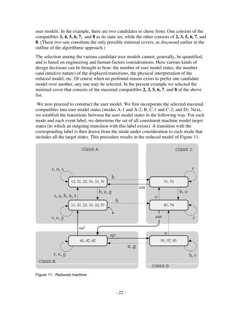
We now proceed to construct the <strong>user</strong> model. We first incorporate the selected maximal<br />
compatibles into <strong>user</strong> model states (modes A-1 <strong>and</strong> A-2; B; C-1 <strong>and</strong> C-2; <strong>and</strong> D). Next,<br />
we establish the transitions between the <strong>user</strong> model states in the following way: For each<br />
mode <strong>and</strong> each event label, we determine the set <strong>of</strong> all constituent machine model target<br />
states (to which an outgoing transition with this label exists). A transition with the<br />
corresponding label is then drawn from the mode under consideration to each mode that<br />
includes all the target states. This procedure results in the reduced model <strong>of</strong> Figure 11.<br />
Figure 11. Reduced machine<br />
- 22 -