AIR-SUSPENSION - Marcle Leisure
AIR-SUSPENSION - Marcle Leisure
AIR-SUSPENSION - Marcle Leisure

Create successful ePaper yourself
Turn your PDF publications into a flip-book with our unique Google optimized e-Paper software.
<strong>AIR</strong>-<strong>SUSPENSION</strong><br />
Dunlop Systems and Components<br />
Het Wegdam 22<br />
7496 CA Hengevelde<br />
The Netherlands<br />
Tel.: +31-(0)547-333065<br />
Fax: +31-(0)547-333068<br />
Website: www.dunlopsystems.com<br />
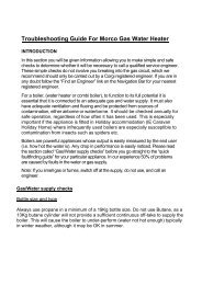
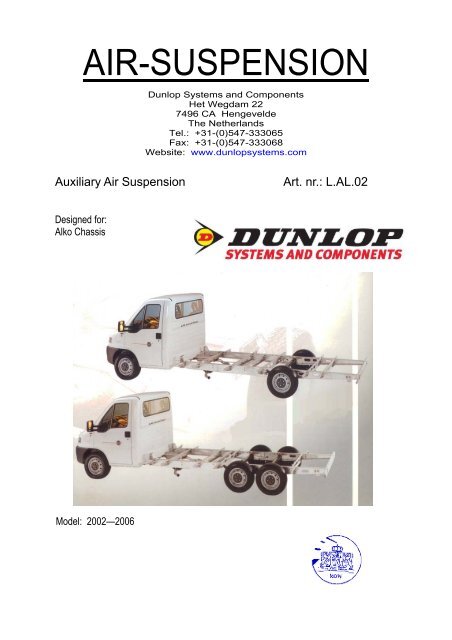
Auxiliary Air Suspension<br />
Art. nr.: L.AL.02<br />
Designed for:<br />
Alko Chassis<br />
Model: 2002—2006
ALKO Chassis 2002—2006<br />
Auxiliary Air Suspension<br />
1. FOREWORD<br />
This manual provides instructions for the installation of an auxiliary air<br />
suspension kit, developed specifically for Motorhomes with an ALKO<br />
torsion axle. To ensure correct installation of the kit, it is strongly<br />
recommend that these instructions are read thoroughly before<br />
commencing any installation work. Installation should only be carried out<br />
by a suitably qualified mechanic or specialist installation facility. Dunlop<br />
Systems and Components will not accept any responsibility for faults or<br />
defects arising from incorrect installation, which automatically renders<br />
the guarantee invalid.<br />
IMPORTANT : Manufacturer’s Declaration Form<br />
A manufacturer’s declaration form is provided with your kit.<br />
Following installation of the kit please ensure that this form is<br />
completed, signed by a qualified fitter and a copy is returned to<br />
Dunlop Systems and Components by post, fax or e-mail.<br />
Artikel number:<br />
L.AL.07<br />
- Auxiliary air suspension for Alko chassis<br />
1. FOREWORD ........................................................... 2<br />
2. INTRODUCTION ..................................................... 3<br />
3. VERY IMPORTANT NOTES ........................................ 3<br />
4. COMPLETE ASSEMBLY ............................................. 5<br />
5. INSTRUCTIONS FOR INSTALLATION .......................... 6<br />
5.1. Installing the lower brackets ................................................ 6<br />
5.2. Installing the upper brackets ............................................... 6<br />
5.3. Installing the air springs ..................................................... 7<br />
5.5. Tube Connection and Disconnection, Cutting and Routing ........ 8<br />
5.6. Brake modification ...................................................................... 9<br />
5.7. Spring inflation .......................................................................... 9<br />
5.8. Maintenance .............................................................................. 9<br />
6. EPILOGUE ............................................................ 10<br />
7. INSTALLATION DRAWINGS ..................................... 11<br />
L.AL.02 2
ALKO Chassis 2002—2006<br />
Auxiliary Air Suspension<br />
2. INTRODUCTION<br />
Thank you for choosing an auxiliary air suspension kit from the range<br />
offered by Dunlop Systems and Components. Auxiliary air suspension is<br />
fitted in tandem with the standard steel springs of the vehicle<br />
suspension, and provides enhancements in terms of both the stability of<br />
the vehicle and the comfort of the passengers…<br />
Vehicle Levelling<br />
Simply by varying the air pressure in the springs, the vehicle can be<br />
levelled both front-to-rear and side-to-side. Keeping the vehicle<br />
level optimises stability, ensures correct headlamp beam distribution<br />
and reduces tyre wear arising from uneven distribution of weight.<br />
Straight Line Stability<br />
Straight line stability is greatly increased at higher speeds, and when<br />
subjected to buffeting from cross-winds or large overtaking vehicles<br />
Reduced Body Roll<br />
Body roll when cornering or negotiating roundabouts is significantly<br />
reduced.<br />
Fatigue Reduction and Wear Compensation<br />
Suspension fatigue is reduced, so helping to prevent leaf springs<br />
from sagging under repeated or constant loading.<br />
Any sagging already present can be compensated-for. This is a<br />
particular benefit for motorhomes, which are always fully laden.<br />
Ride Comfort<br />
Air springs help to absorb shock loads from uneven road surfaces,<br />
therefore general ride quality is much improved.<br />
3. VERY IMPORTANT NOTES<br />
Gross Vehicle Weight (GVW)<br />
Air assist kits are not in themselves designed to increase<br />
the gross vehicle weight (GVW) rating of a vehicle. They<br />
do not legally allow for carriage of a load greater than the<br />
carrying capacity stated on the data plate of the vehicle.<br />
Do not exceed the maximum load specified by the vehicle<br />
manufacturer…<br />
♦ to avoid compromising passenger safety<br />
♦ to prevent possible damage to the vehicle<br />
♦ for legal reasons<br />
L.AL.02 3
ALKO Chassis 2002—2006<br />
Auxiliary Air Suspension<br />
Check the condition of your torsion axle<br />
• Be aware that the torsion axle(s) has to be in a good condition<br />
• Alko advises a revision of the axle every 100,000 – 120,000 km<br />
• Never install helper (air) springs if there are indication of a failure with the<br />
axle.<br />
• Helper (air) springs are only to help the (tired) torsion (springs)<br />
• Check if the vehicle is bending (a lot) to one side (indication of a broken<br />
torsion spring)<br />
• Lift the rear till the lever arm is resting on the bump stop<br />
• Watch the lever arm moving while you lift the rear, these have to move<br />
smoothly (indication of greasing)<br />
• Turn off the radio so you can also listen to the movement, if you indicate a<br />
noise what raises a question mark above your head, this can be a broken<br />
torsion spring<br />
• If you have doubts use a screwdriver (or a stethoscope with a needle if you<br />
have one) to listen on the housing while moving<br />
• Be aware, torsion bars are fixed in the middle and in the lever arm, if all are<br />
broken your lever arm will come out of its housing (While driving!!!!!!)<br />
• There are 2 types of torsion springs; blades 4 or 5 on top of each other to<br />
make a square and the other is; 3 torsion springs with splain teeth<br />
• If one torsion spring is broken, Alko insist in changing them all<br />
• Pull the hand brake and lift by hand a wheel and look at the lever arm in its<br />
housing for backlash, app. 0.5 mm is maximum.<br />
• Try to find out if the bearings have been galling<br />
• Remove the grease nipples and check the quality of the grease<br />
• Always grease the nipples if you have a vehicle where you have to work on.<br />
• If everything is fine you can start installing our air suspension.<br />
Vehicle Uprating<br />
Despite the above words of caution, it is possible to upgrade the weight rating<br />
of your vehicle. This must be carried-out by a specialist supplier that will…<br />
♦<br />
♦<br />
carry out any necessary modifications in addition to fitting the air assist kit<br />
complete documentation as necessary to inform the Vehicle and Operator<br />
Services Agency (VOSA) – a mandatory requirement<br />
♦ supply and fit a new weight plate to replace the original plate supplied with<br />
the vehicle<br />
This process applies to United Kingdom registered vehicles. The process in<br />
other countries may be different.<br />
L.AL.02 4
ALKO Chassis 2002—2006<br />
Auxiliary Air Suspension<br />
4. CONTENTS OF THE <strong>AIR</strong> <strong>SUSPENSION</strong> KIT<br />
Nr. Description<br />
1. Upper bracket – left hand<br />
2. Upper bracket – right hand<br />
3. Under bracket – left/right hand<br />
4. Air spring SZ 55-20<br />
Quantity<br />
1<br />
1<br />
2<br />
2<br />
Not in the assembly drawing<br />
• All bolt and nuts needed<br />
• Bleu and black air lines<br />
• Tie wraps<br />
• Schrader valves<br />
• Declaration of conformity<br />
• Installation manual<br />
L.AL.02 5
ALKO Chassis 2002—2006<br />
Auxiliary Air Suspension<br />
5. INSTRUCTIONS FOR INSTALLATION<br />
Preparation and Precaution<br />
Before beginning installation, ensure that you have sufficient<br />
clearance, the wheels need to be free from the floor. Use a jack<br />
if necessary.<br />
Pay attention to your safety at all times during installation -<br />
always use axle stands to support the vehicle!<br />
The following instructions make reference to the diagrams on pages 12 to<br />
16 inclusive.<br />
5.1 Installing the lower brackets<br />
1. Lift the rear side of the vehicle till there is no tension in the springs.<br />
(picture 1& 2)<br />
2. Insert the key into the centre hole of the suspension arm. (picture 3<br />
& 4)<br />
3. Push the under bracket into the hole till the ribs are in contact with<br />
the suspension arm. (picture 5 & 6).<br />
4. Insert the M12 x 25 bout with washer and spring washer in to the<br />
keyway. Do not tighten totally, alignment need to stay possible.<br />
(picture 7 and 8).<br />
5.2. Installing the upper brackets<br />
6. Remove the clamp strap of the brake hose en take the brake hose<br />
out of its fixing bracket. Remove now the fixing bracket of the chassis.<br />
(picture 9 and 10)<br />
7. Remove the 4 bolts as shown in picture 13 and 14.<br />
8. Prepare the upper bracket for installation, by putting the bolts<br />
trough the holes and to bring the spacer plate. (picture 11and 12)<br />
9. Install the upper bracket to the chassis. (picture 15 and 16)<br />
10. Install the brake line with the clamp to the upper bracket. (picture<br />
26)<br />
L.AL.02 6
ALKO Chassis 2002—2006<br />
Auxiliary Air Suspension<br />
5.3 Installing the air springs<br />
1. Connect the air tube to the air spring. Use black for the left side and<br />
blue for the right side. Than guide the tube through it’s designated<br />
hole in the upper bracket. (the one closest to the chassis, picture 17<br />
and 18)<br />
2. Attach the air spring to the upper bracket, using the M10 x 20 bolt<br />
with washer and locking ring. Do not tighten them yet. (picture 19 &<br />
20 )<br />
3. Lower the vehicle till desired drive height. (picture 21 )<br />
4. Carefully inflate the air spring a bit , so the piston will touch the bottom<br />
bracket.<br />
5. Attach the piston to the bottom bracket with the M12 x 25 bolt with<br />
washer and locking ring. These are also not to be tightened yet.<br />
6. Put a bit pressure (1 bar) on the air spring. Align the air spring and<br />
tighten the bolts on top and bottom of the air spring.<br />
7. Check also the position of the bottom bracket and take care of the<br />
alignment.<br />
8. If the positions are O.K. Tighten the bolt of the keyway. (picture 24<br />
and 25)<br />
L.AL.02 7
ALKO Chassis 2002—2006<br />
Auxiliary Air Suspension<br />
5.5 Tube Connection and Disconnection, Cutting and Routing<br />
Connection and Disconnection<br />
Tubes are connected as shown by the diagrams below...<br />
A B C<br />
A. Slide a nut over the end of the tube<br />
B. Push the tube onto the connector as far as possible<br />
C. Feed the nut up to the connector, fully tighten by hand and finally<br />
tighten one additional turn using spanners<br />
Cutting<br />
To achieve good sealing and air-tight fitting of tube ends to their<br />
connecting parts, it is very important to cut tubing cleanly and squarely.<br />
A dedicated guillotine action tubing cutter is recommended, or a craft<br />
knife if such a tool is not available. Do not use electrician’s side cutters.<br />
A dedicated tubing cutter -<br />
Recommended<br />
Electrician’s Side Cutters<br />
NOT Recommended<br />
Routing<br />
Study the underside of the vehicle and decide how to route each branch<br />
of the air circuit…<br />
• To minimise the risk of chafing, avoid running tubing over metal<br />
edges as much as possible<br />
• Avoid close proximity to heat sources such as the exhaust assembly<br />
• Choose a route that provides as much protection as possible from<br />
dirt, debris and any solid objects that may impact the underside of<br />
the vehicle<br />
It is recommended that tubes are guided alongside brake lines as much<br />
as possible.<br />
L.AL.02 8
ALKO Chassis 2002—2006<br />
Auxiliary Air Suspension<br />
5.6 Brake modification<br />
Your vehicle has ABS so there is no modification needed for your brakes.<br />
5.7 Spring Inflation<br />
Once installation of the air assist kit is complete, inflate the springs via<br />
the inflator console taking careful note of the following...<br />
Maximum and Minimum Pressure<br />
Maximum Pressure 7.0bar Minimum Pressure 0.5bar<br />
Do not exceed 7.0bar (101psi), which is the recommended<br />
maximum charge pressure for the air springs.<br />
The springs may be deflated if the vehicle is to be stored for a<br />
lengthy period without use, but a pressure of at least 0.5bar<br />
(7.25psi) should be maintained at all times in order to avoid<br />
possible compression damage to the springs.<br />
5.8 Maintenance<br />
Following installation, it is recommended that all metal parts are coated<br />
with a protective substance such as body wax.<br />
The system does not require very much maintenance other than…<br />
♦ to maintain air pressure in the springs. Much like a tyre, the system<br />
may lose a little air over time.<br />
♦ to keep the air bellows clean. It is suggested that, when washing<br />
the vehicle, the bellows are inspected and cleaned as necessary<br />
(preferable by spraying). Look in particular for stones or grit<br />
trapped between convolutes, as this may damage the bellow.<br />
L.AL.02 9
ALKO Chassis 2002—2006<br />
Auxiliary Air Suspension<br />
6. EPILOGUE<br />
Dunlop Systems and Components hopes that you enjoy the benefits that<br />
your air suspension system will provide for you. To ensure optimal<br />
performance, we advise that you have your system checked frequently<br />
by qualified personnel. As recommended in the fitting instructions, it is<br />
important to coat all the steel parts with a protective substance such as<br />
body wax.<br />
IMPORTANT : Manufacturer’s Declaration Form<br />
A manufacturer’s declaration form is provided with your kit.<br />
Following installation of the kit please ensure that this form is<br />
completed, signed by a qualified fitter and a copy is returned to<br />
Dunlop Systems and Components by fax, post or e-mail.<br />
As a condition of your warranty, modifications to the system may only be<br />
carried out by personnel of Dunlop Systems and Components.<br />
Enquiries<br />
For general enquiries please either telephone…<br />
Dunlop Systems and Components Nederland : +31 (0)547 33 30 65<br />
Dunlop Systems and Components UK : +44 (0)24 7629 3300<br />
...or e-mail info@dunlopsystems.com.<br />
L.AL.02 10
ALKO Chassis 2002—2006<br />
Auxiliary Air Suspension<br />
9. Installation drawings<br />
1<br />
2<br />
3<br />
4<br />
5<br />
6<br />
7<br />
8<br />
L.AL.02 11
ALKO Chassis 2002—2006<br />
Auxiliary Air Suspension<br />
9<br />
10<br />
11<br />
12<br />
13<br />
14<br />
15<br />
16<br />
L.AL.02 12
ALKO Chassis 2002—2006<br />
Auxiliary Air Suspension<br />
17<br />
18<br />
19<br />
20<br />
21<br />
22<br />
23<br />
24<br />
L.AL.02 13
ALKO Chassis 2002—2006<br />
Auxiliary Air Suspension<br />
25<br />
26<br />
L.AL.02 14