L.D84.C.M - Dunlop Systems & Components
L.D84.C.M - Dunlop Systems & Components
L.D84.C.M - Dunlop Systems & Components

Create successful ePaper yourself
Turn your PDF publications into a flip-book with our unique Google optimized e-Paper software.
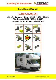
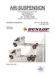
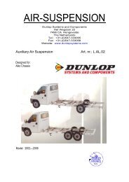
Auxiliary Air Suspension<br />
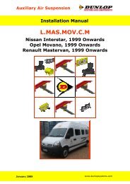
Installation Manual<br />
L.<strong>D84.C</strong>.M<br />
Citroën Jumper / Relay X280/X290 (1984—1993)<br />
Fiat Ducato X280/X290 (1984—1993)<br />
Peugeot Boxer X280/X290 (1984—1993)<br />
November 2008<br />
www.dunlopsystems.com
Citroën Jumper X280/X290 Fiat Ducato X280/X290 Peugeot Boxer X280/X290<br />
L.<strong>D84.C</strong>.M<br />
CONTENTS<br />
1. FOREWORD ........................................................... 3<br />
2. INTRODUCTION ..................................................... 4<br />
3. VERY IMPORTANT NOTES ........................................ 5<br />
4. COMPLETE ASSEMBLY ............................................. 7<br />
5. INSTRUCTIONS FOR INSTALLATION .......................... 8<br />
5.1. Bump Stop Removal and Fitting of Upper Bracket .................. 8<br />
5.2. Fitting of Lower Bracket ...................................................... 8<br />
5.3. Fitting of Air Bellow ............................................................ 9<br />
5.4. Fitting of Inflator Console .................................................. 10<br />
5.5. Tube Connection and Disconnection, Cutting and Routing ....... 11<br />
5.6. Spring Inflation ................................................................ 12<br />
5.7. Spring Alignment .............................................................. 13<br />
5.8. IMPORTANT! Load Sensing Valve (LSV) Adjustment ............... 13<br />
5.9. Maintenance .................................................................... 14<br />
5.10. Installation Drawings ....................................................... 15<br />
6. EPILOGUE ............................................................ 20<br />
<strong>Dunlop</strong> <strong>Systems</strong> and <strong>Components</strong><br />
Het Wegdam 22<br />
7496 CA Hengevelde<br />
Nederland<br />
Tel. +31 (0)547 33 30 65<br />
Fax. +31 (0)547 33 30 68<br />
<strong>Dunlop</strong> <strong>Systems</strong> and <strong>Components</strong><br />
Holbrook Lane<br />
Coventry CV6 4QX<br />
United Kingdom<br />
Tel. +44 (0)24 7629 3300<br />
Fax. +44 (0)24 7629 3390<br />
www.dunlopsystems.com<br />
© 2008, <strong>Dunlop</strong> <strong>Systems</strong> and <strong>Components</strong><br />
RDW : 71/320-015/95<br />
2<br />
www.dunlopsystems.com
Citroën Jumper X280/X290 Fiat Ducato X280/X290 Peugeot Boxer X280/X290<br />
L.<strong>D84.C</strong>.M<br />
1. FOREWORD<br />
This manual provides instructions for the installation of an auxiliary air<br />
suspension kit, developed specifically for the Citroën Jumper/Relay X280/<br />
X290 (C25), Fiat Ducato X280/X290 and Peugeot Boxer X280/X290 (J5).<br />
To ensure correct installation of the kit, it is strongly recommend that<br />
these instructions are read thoroughly before commencing any<br />
installation work. Installation should only be carried out by a suitably<br />
qualified mechanic or specialist installation facility. <strong>Dunlop</strong> <strong>Systems</strong> and<br />
<strong>Components</strong> will not accept any responsibility for faults or defects arising<br />
from incorrect installation, which automatically renders the guarantee<br />
invalid.<br />
IMPORTANT : Manufacturer’s Declaration Form<br />
A manufacturer’s declaration form is provided with your kit.<br />
Following installation of the kit please ensure that this form is<br />
completed, signed by a qualified fitter and returned to <strong>Dunlop</strong><br />
<strong>Systems</strong> and <strong>Components</strong>.<br />
This kit is suitable for motorhomes and other vehicles with a minimum<br />
rear axle load of 1550kg (3417lbs).<br />
RDW : 71/320-015/95<br />
3<br />
www.dunlopsystems.com
Citroën Jumper X280/X290 Fiat Ducato X280/X290 Peugeot Boxer X280/X290<br />
L.<strong>D84.C</strong>.M<br />
2. INTRODUCTION<br />
Thank you for choosing an auxiliary air suspension kit from the range<br />
offered by <strong>Dunlop</strong> <strong>Systems</strong> and <strong>Components</strong>. Auxiliary air suspension is<br />
fitted in tandem with the standard steel springs of the vehicle<br />
suspension, and provides enhancements in terms of both the stability of<br />
the vehicle and the comfort of the passengers…<br />
Vehicle Levelling<br />
Simply by varying the air pressure in the springs, the vehicle can be<br />
levelled both front-to-rear and side-to-side. Keeping the vehicle<br />
level optimises stability, ensures correct headlamp beam distribution<br />
and reduces tyre wear arising from uneven distribution of weight.<br />
Straight Line Stability<br />
Straight line stability is greatly increased at higher speeds, and when<br />
subjected to buffeting from cross-winds or large overtaking vehicles<br />
Reduced Body Roll<br />
Body roll when cornering or negotiating roundabouts is significantly<br />
reduced.<br />
Fatigue Reduction and Wear Compensation<br />
Suspension fatigue is reduced, so helping to prevent leaf springs<br />
from sagging under repeated or constant loading.<br />
Any sagging already present can be compensated-for. This is a<br />
particular benefit for motorhomes, which are always fully laden.<br />
Ride Comfort<br />
Air springs help to absorb shock loads from uneven road surfaces,<br />
therefore general ride quality is much improved.<br />
RDW : 71/320-015/95<br />
4<br />
www.dunlopsystems.com
Citroën Jumper X280/X290 Fiat Ducato X280/X290 Peugeot Boxer X280/X290<br />
L.<strong>D84.C</strong>.M<br />
3. VERY IMPORTANT NOTES<br />
Gross Vehicle Weight (GVW)<br />
Air assist kits are not in themselves designed to increase<br />
the gross vehicle weight (GVW) rating of a vehicle. They<br />
do not legally allow for carriage of a load greater than the<br />
carrying capacity stated on the data plate of the vehicle.<br />
Do not exceed the maximum load specified by the vehicle<br />
manufacturer…<br />
♦ to avoid compromising passenger safety<br />
♦ to prevent possible damage to the vehicle<br />
♦ for legal reasons<br />
Load Sensing Valve (LSV) Adjustment<br />
If your vehicle is not fitted with an antilock braking system<br />
(ABS) then it will have a load sensing valve (LSV) to<br />
automatically adjust braking force under varying load conditions.<br />
This valve must be adjusted immediately after the fitting of an<br />
air assist kit and before the vehicle is driven again on public<br />
roads.<br />
If the LSV is not adjusted following the fitting of an air assist kit,<br />
it may misjudge rear load conditions to the extent that the<br />
braking pressure applied to the rear brakes is not correct (e.g.<br />
the rear wheels may lock with no load on the rear axle). The<br />
consequences of this in terms of vehicle stability and safety are<br />
potentially serious.<br />
Vehicle Uprating<br />
Despite the above words of caution, it is possible to upgrade the weight<br />
rating of your vehicle. This must be carried-out by a specialist supplier<br />
that will…<br />
♦ carry out any necessary modifications in addition to fitting the air<br />
assist kit<br />
♦ complete documentation as necessary to inform the Vehicle and<br />
Operator Services Agency (VOSA) – a mandatory requirement<br />
♦<br />
supply and fit a new weight plate to replace the original plate<br />
supplied with the vehicle<br />
This process applies to United Kingdom registered vehicles. The process<br />
in other countries may be different.<br />
RDW : 71/320-015/95<br />
5<br />
www.dunlopsystems.com
Citroën Jumper X280/X290 Fiat Ducato X280/X290 Peugeot Boxer X280/X290<br />
L.<strong>D84.C</strong>.M<br />
Safety Guidance Note<br />
The following very useful guidance note is available for free download<br />
from the Health and Safety Executive (HSE)…<br />
PM85, July 2007 Safe recovery (and repair) of buses and coaches fitted<br />
with air suspension<br />
The uniform resource locator (URL) for this document is…<br />
http://www.hse.gov.uk/PUBNS/pm85.pdf<br />
RDW : 71/320-015/95<br />
6<br />
www.dunlopsystems.com
Citroën Jumper X280/X290 Fiat Ducato X280/X290 Peugeot Boxer X280/X290<br />
L.<strong>D84.C</strong>.M<br />
4. COMPLETE ASSEMBLY<br />
The complete assembly is shown by the diagrams below...<br />
Figure 1(a). Bellow and Brackets<br />
Figure 1(b)<br />
Configuration for vehicle with standard bump stop<br />
Figure 1(c)<br />
Configuration for vehicle with lowered bump stop<br />
Figures 1(b) and (c) above illustrate that the upper air spring brackets of<br />
your kit are adjustable according to whether your vehicle is fitted with a<br />
standard bump stop (1(b)) or a lowered bump stop (1(c)).<br />
RDW : 71/320-015/95<br />
7<br />
www.dunlopsystems.com
Citroën Jumper X280/X290 Fiat Ducato X280/X290 Peugeot Boxer X280/X290<br />
L.<strong>D84.C</strong>.M<br />
5. INSTRUCTIONS FOR INSTALLATION<br />
Preparation and Precaution<br />
Before beginning installation, ensure that you have sufficient<br />
clearance between the axle and the chassis. Use a jack if<br />
necessary. Install at one side of the vehicle at a time.<br />
Pay attention to your safety at all times during installation -<br />
always use axle stands to support the vehicle!<br />
The following instructions make reference to the diagrams on<br />
pages 16 to 19 inclusive.<br />
5.1 Bump Stop Removal and Fitting of Upper Bracket<br />
i. Remove the bump stop by prizing it away from its mount— Figures 1<br />
and 2. One of the two holes vacated by removal of the bump stop<br />
will be used for attachment of the upper bracket.<br />
ii. Attach the upper bracket to the chassis, such that the lower flange<br />
of the bracket presses against the lower part of the chassis rail—<br />
Figures 3 to 5. It is likely that you will need to loosen the two bolts<br />
that hold together the two slidable parts of the bracket and then retighten<br />
them once the bracket is in place against the chassis.<br />
iii. The upper bracket has a nut welded to it to which the small L-<br />
shaped bracket is attached. Attach this small bracket such that its<br />
‘lip’ part is over the seam of the chassis—Figures 6 and 7.<br />
5.2 Fitting of Lower Bracket<br />
The lower bracket is attached directly beneath the upper bracket, making<br />
use of two flanges built on to the axle with which the bump stop would<br />
have been in contact when the vehicle suspension was in its compressed<br />
(‘bump’) position—Figure 8.<br />
i. Place the lower bracket in position against the axle—Figures 9 and<br />
10<br />
ii. Secure the lower bracket to the axle flanges using the two small U-<br />
shaped brackets—Figures 11 and 12<br />
RDW : 71/320-015/95<br />
8<br />
www.dunlopsystems.com
Citroën Jumper X280/X290 Fiat Ducato X280/X290 Peugeot Boxer X280/X290<br />
5.3 Fitting of Air Bellow<br />
L.<strong>D84.C</strong>.M<br />
i. See Section 5.5 - “Tube Connection and Disconnection, Cutting and<br />
Routing” : Connect a tube to the bellow by pushing the tube into the<br />
air inlet port on the underside of the spring and then hand-rotating<br />
the tube by one screw turn. Use black tubing for the left-hand<br />
bellow and blue for the right-hand bellow. Feed the tube through<br />
the hole in the upper bracket.<br />
ii. Place the bellow into position between the upper and lower<br />
brackets—Figures 14 and 15<br />
iii. Attach the bellow to the upper bracket using two M8 x 16mm bolts<br />
and two spring washers—Figure 16. Do not fully tighten the bolts at<br />
this stage because the bellow may require alignment once inflated<br />
(Section 5.7).<br />
iv. Attach the bellow to the lower bracket using two M8 x 16mm bolts<br />
and two spring washers—Figure 16. Do not fully tighten the bolts at<br />
this stage because the bellow may require alignment once inflated<br />
(Section 5.7).<br />
RDW : 71/320-015/95<br />
9<br />
www.dunlopsystems.com
Citroën Jumper X280/X290 Fiat Ducato X280/X290 Peugeot Boxer X280/X290<br />
L.<strong>D84.C</strong>.M<br />
5.4 Fitting of Inflator Console<br />
Standard Option 1<br />
Option 2 Option 3<br />
Your kit is supplied with one of the inflator console options shown above…<br />
• ‘Standard’, having two valves only (above, top-left)<br />
• ‘Option 1’, ‘Option 2’ or ‘Option 3’, having both valves and pressure<br />
gauges<br />
Mount the console in a position of your choice whereby it is firmly fixed,<br />
has some protection from the environment (particularly important for the<br />
console with gauges) and is easily accessible. Suggested possible<br />
locations include...<br />
Console with Valves Only…<br />
• on the rear bumper<br />
• at the rear beside the license<br />
plate<br />
• on the chassis next to a rear<br />
wheel<br />
• in a service shutter<br />
• beside the fuel cap<br />
Console with Valves and Gauges…<br />
• in the vehicle cabin, within reach<br />
and sight of the driver<br />
• in the wall of a cupboard<br />
(motorhomes)<br />
• in a service shutter<br />
‘Comfort’ Packages<br />
The ‘Option 2’ and ‘Option 3’ panels, as shown above, are each part of a<br />
Comfort Package that is supplied with a compressor (and also an air<br />
reservoir in the case of the ‘Option 3’ panel) for ease of spring inflation<br />
and ride height setting. For further information please ask your dealer.<br />
RDW : 71/320-015/95<br />
10<br />
www.dunlopsystems.com
Citroën Jumper X280/X290 Fiat Ducato X280/X290 Peugeot Boxer X280/X290<br />
L.<strong>D84.C</strong>.M<br />
5.5 Tube Connection and Disconnection, Cutting and Routing<br />
Connection and Disconnection<br />
Tubes are connected as shown by the diagrams below...<br />
A B C<br />
A. Slide a nut over the end of the tube<br />
B. Push the tube onto the connector as far as possible<br />
C. Feed the nut up to the connector, fully tighten by hand and finally<br />
tighten one additional turn using spanners<br />
Cutting<br />
To achieve good sealing and air-tight fitting of tube ends to their<br />
connecting parts, it is very important to cut tubing cleanly and squarely.<br />
A dedicated guillotine action tubing cutter is recommended, or a craft<br />
knife if such a tool is not available. Do not use electrician’s side cutters.<br />
A dedicated tubing cutter -<br />
Recommended<br />
Electrician’s Side Cutters<br />
NOT Recommended<br />
RDW : 71/320-015/95<br />
11<br />
www.dunlopsystems.com
Citroën Jumper X280/X290 Fiat Ducato X280/X290 Peugeot Boxer X280/X290<br />
L.<strong>D84.C</strong>.M<br />
Routing<br />
Study the underside of the vehicle and decide how to route each branch<br />
of the air circuit…<br />
• To minimise the risk of chafing, avoid running tubing over metal<br />
edges as much as possible<br />
• Avoid close proximity to heat sources such as the exhaust assembly<br />
• Choose a route that provides as much protection as possible from<br />
dirt, debris and any solid objects that may impact the underside of<br />
the vehicle<br />
It is recommended that tubes are guided alongside brake lines as much<br />
as possible.<br />
Use cable ties (‘tie wraps’) to secure tubing to the chassis, taking<br />
care not to over-tighten them.<br />
5.6 Spring Inflation<br />
Once installation of the air assist kit is complete, inflate the springs via<br />
the inflator console taking careful note of the following...<br />
Maximum and Minimum Pressure<br />
Maximum Pressure 7.0bar Minimum Pressure 0.5bar<br />
Do not exceed 7.0bar (101psi), which is the recommended<br />
maximum charge pressure for the air springs.<br />
The springs may be deflated if the vehicle is to be stored for a<br />
lengthy period without use, but a pressure of at least 0.5bar<br />
(7.25psi) should be maintained at all times in order to avoid<br />
possible compression damage to the springs.<br />
RDW : 71/320-015/95<br />
12<br />
www.dunlopsystems.com
Citroën Jumper X280/X290 Fiat Ducato X280/X290 Peugeot Boxer X280/X290<br />
5.7 Spring Alignment<br />
L.<strong>D84.C</strong>.M<br />
Spring out of alignment—<br />
mounting plate axes offset<br />
Spring in alignment—<br />
mounting plates parallel<br />
and coaxial<br />
CAUTION!<br />
Before fully tightening the bolts that secure the air spring to the<br />
upper and lower brackets, set the vehicle at ride height (spring<br />
height approximately 14cm) and ensure that the springs are<br />
correctly aligned.<br />
5.8 IMPORTANT! Load Sensing Valve (LSV) Adjustment<br />
Once the auxiliary air suspension system is installed and the bellows are<br />
inflated such that the desired vehicle ride height is achieved, the LSV<br />
assembly must be modified—see Figures 19 to 29 inclusive. This<br />
involves fitting two brackets, as supplied in your kit, to the existing<br />
assembly.<br />
i. Detach and remove the upper of the two interconnected brackets—<br />
Figures 19 to 22 inclusive<br />
ii. Detach the LSV rod hinge from its supporting bracket—Figure 23<br />
iii. Mate the adaptor bracket to the hinge-supporting bracket and then<br />
reattach the hinge—Figures 24 and 25<br />
iv. Attach the slotted bracket supplied to the existing LSV axle bracket,<br />
with the exposed end of the LSV rod through the slot in the bracket<br />
—Figures 26 and 27<br />
v. Secure the exposed end of the LSV rod to the slotted bracket by<br />
push-fitting the clamping ring provided—Figures 28 and 29<br />
RDW : 71/320-015/95<br />
13<br />
www.dunlopsystems.com
Citroën Jumper X280/X290 Fiat Ducato X280/X290 Peugeot Boxer X280/X290<br />
5.9 Maintenance<br />
L.<strong>D84.C</strong>.M<br />
Following installation, it is recommended that all metal parts are coated<br />
with a protective substance such as body wax.<br />
The system does not require very much maintenance other than…<br />
♦ to maintain air pressure in the springs. Much like a tyre, the system<br />
may lose a little air over time.<br />
♦ to keep the air bellows clean. It is suggested that, when washing<br />
the vehicle, the bellows are inspected and cleaned as necessary<br />
(preferable by spraying). Look in particular for stones or grit<br />
trapped between convolutes, as this may damage the bellow.<br />
RDW : 71/320-015/95<br />
14<br />
www.dunlopsystems.com
Citroën Jumper X280/X290 Fiat Ducato X280/X290 Peugeot Boxer X280/X290<br />
5.10 Installation Drawings<br />
L.<strong>D84.C</strong>.M<br />
RDW : 71/320-015/95<br />
15<br />
www.dunlopsystems.com
Citroën Jumper X280/X290 Fiat Ducato X280/X290 Peugeot Boxer X280/X290<br />
L.<strong>D84.C</strong>.M<br />
1 2<br />
3 4<br />
5 6<br />
7 8<br />
RDW : 71/320-015/95<br />
16<br />
www.dunlopsystems.com
Citroën Jumper X280/X290 Fiat Ducato X280/X290 Peugeot Boxer X280/X290<br />
L.<strong>D84.C</strong>.M<br />
9 10<br />
11 12<br />
13 14<br />
15 16<br />
RDW : 71/320-015/95<br />
17<br />
www.dunlopsystems.com
Citroën Jumper X280/X290 Fiat Ducato X280/X290 Peugeot Boxer X280/X290<br />
L.<strong>D84.C</strong>.M<br />
17 18<br />
Spring out of<br />
alignment—mounting<br />
plate axes offset<br />
Spring in alignment—<br />
mounting plates parallel<br />
and coaxial<br />
19 20<br />
CAUTION!<br />
Before fully tightening the bolts that secure<br />
the air spring to the upper and lower<br />
brackets, set the vehicle at ride height<br />
(spring height approximately 13.5cm) and<br />
ensure that the springs are correctly aligned.<br />
21 22<br />
23 24<br />
RDW : 71/320-015/95<br />
18<br />
www.dunlopsystems.com
Citroën Jumper X280/X290 Fiat Ducato X280/X290 Peugeot Boxer X280/X290<br />
L.<strong>D84.C</strong>.M<br />
25<br />
26<br />
27 28<br />
29<br />
RDW : 71/320-015/95<br />
19<br />
www.dunlopsystems.com
Citroën Jumper X280/X290 Fiat Ducato X280/X290 Peugeot Boxer X280/X290<br />
L.<strong>D84.C</strong>.M<br />
6. EPILOGUE<br />
<strong>Dunlop</strong> <strong>Systems</strong> and <strong>Components</strong> hopes that you enjoy the benefits that<br />
your air suspension system will provide for you. To ensure optimal<br />
performance, we advise that you have your system checked frequently<br />
by qualified personnel. As recommended in the fitting instructions, it is<br />
important to coat all the steel parts with a protective substance such as<br />
body wax.<br />
IMPORTANT : Manufacturer’s Declaration Form<br />
A manufacturer’s declaration form is provided with your kit.<br />
Following installation of the kit please ensure that this form is<br />
completed, signed by a qualified fitter and returned to <strong>Dunlop</strong><br />
<strong>Systems</strong> and <strong>Components</strong>.<br />
As a condition of your warranty, modifications to the system may only be<br />
carried out by personnel of <strong>Dunlop</strong> <strong>Systems</strong> and <strong>Components</strong>.<br />
Enquiries<br />
For general enquiries please either telephone…<br />
<strong>Dunlop</strong> <strong>Systems</strong> and <strong>Components</strong> Nederland : +31 (0)547 33 30 65<br />
<strong>Dunlop</strong> <strong>Systems</strong> and <strong>Components</strong> UK : +44 (0)24 7629 3300<br />
...or e-mail info@dunlopsystems.com.<br />
RDW : 71/320-015/95<br />
20<br />
www.dunlopsystems.com
Auxiliary Air Suspension<br />
<strong>Dunlop</strong> <strong>Systems</strong> and <strong>Components</strong><br />
Het Wegdam 22<br />
7496 CA Hengevelde<br />
Nederland<br />
Tel. +31 (0)547 33 30 65<br />
Fax. +31 (0)547 33 30 68<br />
<strong>Dunlop</strong> <strong>Systems</strong> and <strong>Components</strong><br />
Holbrook Lane<br />
Coventry CV6 4QX<br />
United Kingdom<br />
Tel. +44 (0)24 7629 3300<br />
Fax. +44 (0)24 7629 3390<br />
www.dunlopsystems.com