Proper Exposure Calculation And the Compromise between ... - KIWO
Proper Exposure Calculation And the Compromise between ... - KIWO
Proper Exposure Calculation And the Compromise between ... - KIWO

Create successful ePaper yourself
Turn your PDF publications into a flip-book with our unique Google optimized e-Paper software.
<strong>Proper</strong> <strong>Exposure</strong> <strong>Calculation</strong><br />
<strong>And</strong> <strong>the</strong> <strong>Compromise</strong> <strong>between</strong> Resistance and Resolution<br />
<strong>Proper</strong> stencil exposure can be described as <strong>the</strong><br />
point at which <strong>the</strong> emulsion reaches a<br />
synergistic balance <strong>between</strong> resistance and<br />
resolution. <strong>Proper</strong> exposure is dynamic in<br />
nature, as it fluctuates with printing requirements<br />
and <strong>the</strong> quality and consistency not only of <strong>the</strong><br />
artwork and <strong>the</strong> screen, but also of <strong>the</strong><br />
equipment used to generate <strong>the</strong> art and <strong>the</strong><br />
screen. Environmental conditions constitute<br />
ano<strong>the</strong>r dynamic force in play. Understanding<br />
how each of <strong>the</strong>se variables impact proper<br />
exposure, helps us establish mechanisms for<br />
controlling <strong>the</strong>m. Likewise, this improves our<br />
ability to tighten production parameters, which<br />
leads to higher quality and more consistent<br />
product reliability.<br />
Since proper exposure is predicated on dynamic<br />
variables, it stands to reason frequent exposure<br />
calibrations are required to maintain exposure<br />
control and to assure quality control. They<br />
should be done for each mesh count and<br />
whenever changing mesh, emulsion, coating<br />
technique, exposure lamps and distance.<br />
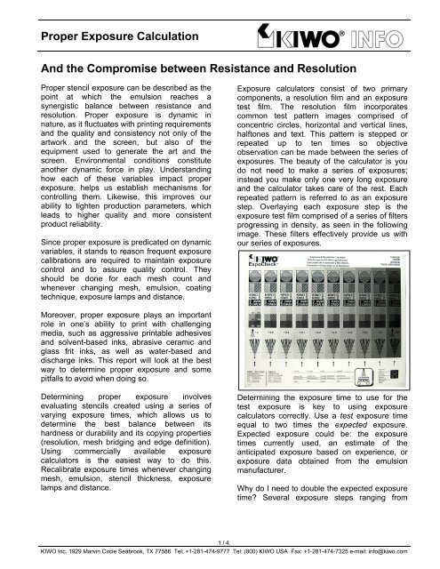
<strong>Exposure</strong> calculators consist of two primary<br />
components, a resolution film and an exposure<br />
test film. The resolution film incorporates<br />
common test pattern images comprised of<br />
concentric circles, horizontal and vertical lines,<br />
halftones and text. This pattern is stepped or<br />
repeated up to ten times so objective<br />
observation can be made <strong>between</strong> <strong>the</strong> series of<br />
exposures. The beauty of <strong>the</strong> calculator is you<br />
do not need to make a series of exposures;<br />
instead you make only one very long exposure<br />
and <strong>the</strong> calculator takes care of <strong>the</strong> rest. Each<br />
repeated pattern is referred to as an exposure<br />
step. Overlaying each exposure step is <strong>the</strong><br />
exposure test film comprised of a series of filters<br />
progressing in density, as seen in <strong>the</strong> following<br />
image. These filters effectively provide us with<br />
our series of exposures.<br />
Moreover, proper exposure plays an important<br />
role in one’s ability to print with challenging<br />
media, such as aggressive printable adhesives<br />
and solvent-based inks, abrasive ceramic and<br />
glass frit inks, as well as water-based and<br />
discharge inks. This report will look at <strong>the</strong> best<br />
way to determine proper exposure and some<br />
pitfalls to avoid when doing so.<br />
Determining proper exposure involves<br />
evaluating stencils created using a series of<br />
varying exposure times, which allows us to<br />
determine <strong>the</strong> best balance <strong>between</strong> its<br />
hardness or durability and its copying properties<br />
(resolution, mesh bridging and edge definition).<br />
Using commercially available exposure<br />
calculators is <strong>the</strong> easiest way to do this.<br />
Recalibrate exposure times whenever changing<br />
mesh, emulsion, stencil thickness, exposure<br />
lamps and distance.<br />
Determining <strong>the</strong> exposure time to use for <strong>the</strong><br />
test exposure is key to using exposure<br />
calculators correctly. Use a test exposure time<br />
equal to two times <strong>the</strong> expected exposure.<br />
Expected exposure could be: <strong>the</strong> exposure<br />
times currently used, an estimate of <strong>the</strong><br />
anticipated exposure based on experience, or<br />
exposure data obtained from <strong>the</strong> emulsion<br />
manufacturer.<br />
Why do I need to double <strong>the</strong> expected exposure<br />
time Several exposure steps ranging from<br />
1 / 4.<br />
<strong>KIWO</strong> Inc. 1929 Marvin Circle Seabrook, TX 77586 Tel: +1-281-474-9777 Tel: (800) <strong>KIWO</strong> USA Fax: +1-281-474-7325 e-mail: info@kiwo.com
under to overexposure are needed to properly<br />
identify <strong>the</strong> step where no visible color variation<br />
is seen <strong>between</strong> adjoining steps or <strong>between</strong><br />
adjacent filtered and unfiltered portions of <strong>the</strong><br />
calculator. In o<strong>the</strong>r words, which step shows no<br />
visible appearance of <strong>the</strong> rectangular filter<br />
covering <strong>the</strong> emulsion The following picture of<br />
an exposure test shows a black line at this point.<br />
All exposure steps left of <strong>the</strong> black line show no<br />
color variation <strong>between</strong> <strong>the</strong> facing arrows along<br />
<strong>the</strong> bottom of <strong>the</strong> stencil, while exposure steps<br />
right of <strong>the</strong> line do.<br />
diazo wanes <strong>the</strong> closer <strong>the</strong>y get to full exposure,<br />
thus <strong>the</strong> color change.<br />
Although I confess SBQ emulsions are more<br />
difficult to gauge, especially on fine meshes,<br />
because <strong>the</strong>y are comprised of only one color,<br />
and technically speaking I suppose <strong>the</strong>re cannot<br />
be a “color” change if only one color is present,<br />
but I still contend <strong>the</strong>re is a color shift attributed<br />
to density. This is illustrated in <strong>the</strong> following<br />
picture of a red pigmented SBQ emulsion.<br />
Notice <strong>the</strong> changes from step to step as viewed<br />
from right to left. Then about midway you no<br />
longer see any changes <strong>between</strong> <strong>the</strong> steps. The<br />
color changes because emulsion washes away<br />
from <strong>the</strong> squeegee side of <strong>the</strong> screen when<br />
developing <strong>the</strong> under exposed steps leaving a<br />
thin, lighter colored stencil. When <strong>the</strong> color stops<br />
changing you know <strong>the</strong> emulsion is adequately<br />
cured because no emulsion washes away.<br />
<strong>Proper</strong>ly cured emulsion solves common stencil<br />
related problems like excessive pinholes, stencil<br />
breakdown, reclaiming difficulties and emulsion<br />
stains.<br />
Therefore, <strong>the</strong> first exposure step left of <strong>the</strong><br />
black line is considered to have received<br />
enough UV to provide very good chemical and<br />
mechanical resistance. This completes step one<br />
of <strong>the</strong> two-step process of determining proper<br />
stencil exposure.<br />
Before we move on to step two, I would like to<br />
address a common belief in <strong>the</strong> industry as it<br />
relates to using color change as a way of<br />
determining proper exposure.<br />
A common misconception is that color variation,<br />
or <strong>the</strong> point of “no color change”, can only be<br />
used to gauge expose times of diazo sensitized<br />
emulsions, but not pre-sensitized SBQ<br />
emulsions a.k.a. “pure photopolymers”. This<br />
originates from <strong>the</strong> fact diazo sensitized<br />
emulsions consist of two colors, yellow (<strong>the</strong><br />
color of diazo) and whatever pigment (blue, red,<br />
violet, etc.) is used to color <strong>the</strong> emulsion. As<br />
<strong>the</strong>se emulsions cure, <strong>the</strong> yellow cast from <strong>the</strong><br />
Each step has an associated number (as seen<br />
in <strong>the</strong> image below) that is used as <strong>the</strong> multiplier<br />
for calculating <strong>the</strong> representative exposure for<br />
that step. This number is multiplied by <strong>the</strong> time<br />
used to expose <strong>the</strong> calculator.<br />
2 / 4
For example, if 60 seconds represents <strong>the</strong> time<br />
used to expose <strong>the</strong> calculator and 0.6<br />
represents <strong>the</strong> point of no color change, <strong>the</strong>n 36<br />
seconds (60x0.6) represents <strong>the</strong> exposure time<br />
of that step. 0.6 indicates <strong>the</strong> percentage (60%)<br />
of light transmission at that exposure step, or<br />
<strong>the</strong> inverse of <strong>the</strong> neutral density filter. The<br />
result is <strong>the</strong> recommended exposure time to<br />
properly harden <strong>the</strong> emulsion and achieve very<br />
good resistance.<br />
Identifying where no color change occurs can be<br />
done immediately after developing <strong>the</strong> screen<br />
while it is wet or after <strong>the</strong> screen dries. More<br />
steps of visible color change occur when<br />
evaluating a damp screen, thus reflecting a<br />
longer exposure time, and fewer steps of visible<br />
color change occur when viewing a dry screen.<br />
Why is <strong>the</strong>re a difference <strong>between</strong> a wet screen<br />
and a dry screen A wet screen is slightly<br />
swollen from absorbing water, which makes<br />
observing slight color variations easier.<br />
Which method should I use Debates reign.<br />
Arguments can be made supporting both<br />
methods. The size of <strong>the</strong> job and/or how<br />
detailed <strong>the</strong> artwork is may help determine <strong>the</strong><br />
method to use, however, <strong>the</strong> type of ink required<br />
for <strong>the</strong> job is <strong>the</strong> clear determining factor for me.<br />
When <strong>the</strong> job calls for characteristically<br />
challenging or aggressive inks, I use a wet<br />
screen to select and calculate exposures.<br />
Textile printers using water-based and<br />
discharge inks, for example, should choose <strong>the</strong>ir<br />
exposure times from a wet screen to enhance<br />
screen longevity. Longer exposure times offer<br />
extra insurance especially for long runs.<br />
Far too often printers err on <strong>the</strong> side of shorter<br />
exposures instead of erring on <strong>the</strong> side of longer<br />
exposures, and it is not always because <strong>the</strong>y<br />
are pressed for time. Often times it is attributed<br />
to one or more of <strong>the</strong> following:<br />
• Film positives lack density (poor D-max)<br />
• Using inappropriate mesh count for <strong>the</strong><br />
detail involved<br />
• Using stencils that are too thick<br />
• Printing halftones or process color from<br />
linearly output film<br />
• Using exposure units with poor vacuum<br />
drawdown<br />
• Starting exposure before adequate<br />
vacuum is reached<br />
• Using poorly designed exposure systems<br />
Get <strong>the</strong>se variables under control and you will<br />
be amazed by <strong>the</strong> amount of processing latitude<br />
you have and how forgiving <strong>the</strong> process<br />
becomes.<br />
As mentioned earlier, determining <strong>the</strong> point of<br />
no color change is just <strong>the</strong> first step of a twostep<br />
process for calibrating proper expose.<br />
Step two is determining whe<strong>the</strong>r <strong>the</strong> stencils<br />
copying properties (resolution, mesh bridging,<br />
and edge definition) meet or exceed production<br />
requirements. Make sure to evaluate <strong>the</strong><br />
appropriate exposure step selecting in step one.<br />
A common mistake made in evaluating copying<br />
properties, especially resolution, is making an<br />
assessment based on whe<strong>the</strong>r or not <strong>the</strong> finest<br />
details of <strong>the</strong> exposure calculator are open. Use<br />
this as a gauge only if production art details are<br />
as fine. Do not sacrifice <strong>the</strong> stencils durability by<br />
selecting a step with a shorter exposure time in<br />
order to capture details you will not print in<br />
production.<br />
Ano<strong>the</strong>r common mistake is trying to capture<br />
details that are not even printable. Much of <strong>the</strong><br />
halftone artwork I see today contains some<br />
highlight and shadow dots that are too small to<br />
be printed successfully. This is not to say I<br />
cannot resolve most of <strong>the</strong>m in <strong>the</strong> screen, as<br />
often times i can, but <strong>the</strong>y will not print properly,<br />
if at all. Unknowingly, but innocently, <strong>the</strong> screen<br />
department adjusts exposure times lower in an<br />
effort to open up every highlight dot on <strong>the</strong> film<br />
positive. This is one of <strong>the</strong> root causes why <strong>the</strong><br />
vast majority of screen printers under expose<br />
screens, <strong>the</strong>n suffer from <strong>the</strong> consequences.<br />
3 / 4
Take for example <strong>the</strong> following stenciled image of<br />
fine highlight dots. The emulsion did resolve <strong>the</strong><br />
dots but it doesn’t look like it because <strong>the</strong> dots are<br />
too small to print properly, meaning over half of<br />
<strong>the</strong> dots are fully or partially blocked by <strong>the</strong><br />
threads. Only <strong>the</strong> dots positioned directly over <strong>the</strong><br />
mesh openings will print. This is a leading cause<br />
of regional moiré in highlight areas of <strong>the</strong> print.<br />
To help avoid falling into <strong>the</strong> trap of under<br />
exposing screens and suffering from printing<br />
inconsistencies, control <strong>the</strong> artwork so <strong>the</strong> finest<br />
detail width is equal <strong>the</strong> width of at least two mesh<br />
openings plus one thread, or twice <strong>the</strong> screen<br />
(mesh + emulsion) thickness. Of course this is not<br />
always possible but <strong>the</strong> closer you adhere to this<br />
rule, <strong>the</strong> less likely you will be to encounter<br />
inexplicable printing problems often caused by<br />
underexposed screens, and <strong>the</strong> simpler <strong>the</strong><br />
printing process will be.<br />
Now take a look at ano<strong>the</strong>r example this time<br />
looking at shadow dots. Again, <strong>the</strong> emulsion<br />
resolved <strong>the</strong> dots however, because <strong>the</strong> dots are<br />
so small, <strong>the</strong> print from this stencil will result in<br />
solid 100% coverage as a result of dot gain once<br />
<strong>the</strong> ink levels out leaving no shadow detail.<br />
Ano<strong>the</strong>r example below shows poor art-to-mesh<br />
relationship as it relates to text. In this example<br />
you see <strong>the</strong> letter F – although fully resolved by<br />
<strong>the</strong> emulsion – falls directly on a thread, while <strong>the</strong><br />
letter L luckily falls in <strong>between</strong> <strong>the</strong> threads. This<br />
case illustrates how choosing <strong>the</strong> wrong mesh<br />
count also causes problems. The mesh count<br />
here is a 156-64, which clearly is unable to<br />
support this fine detail. This artwork requires a<br />
much finer mesh count.<br />
It is in situations like <strong>the</strong>se we’ve just looked at<br />
that throws off <strong>the</strong> synergistic balance <strong>between</strong><br />
stencil durability and resolution. It becomes<br />
wrongly skewed towards <strong>the</strong> resolution side<br />
unjustly sacrificing durability. What can we do to<br />
circumvent this from happening<br />
Understanding <strong>the</strong> art-to-mesh relationship and<br />
how it impacts not only your printing but also your<br />
process, helps you make more informed decisions<br />
as <strong>the</strong>y relate to artwork limitations, mesh<br />
selection, and screen making.<br />
Written by:<br />
Dave Dennings<br />
Product Manager<br />
Screen Making Products<br />
<strong>KIWO</strong> Inc.<br />
Member of <strong>the</strong> Academy of Screen Printing<br />
Technology (ASPT)<br />
4 / 4.<br />
<strong>KIWO</strong> Inc. 1929 Marvin Circle Seabrook, TX 77586 Tel: +1-281-474-9777 Tel: (800) <strong>KIWO</strong> USA Fax: +1-281-474-7325 e-mail: info@kiwo.com