Lamination of Volvo Penta IPS hull mold plugs - Haisma Scheeps
Lamination of Volvo Penta IPS hull mold plugs - Haisma Scheeps
Lamination of Volvo Penta IPS hull mold plugs - Haisma Scheeps
- No tags were found...

You also want an ePaper? Increase the reach of your titles
YUMPU automatically turns print PDFs into web optimized ePapers that Google loves.
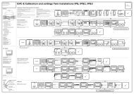
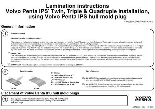
<strong>Lamination</strong> instructions<br />
<strong>Volvo</strong> <strong>Penta</strong> <strong>IPS</strong> * Twin, Triple & Quadruple installation,<br />
using <strong>Volvo</strong> <strong>Penta</strong> <strong>IPS</strong> <strong>hull</strong> <strong>mold</strong> plug<br />
General information<br />
* <strong>IPS</strong>350/400/450/500/550G/600<br />
1<br />
<strong>Lamination</strong> policy<br />
Why use <strong>Volvo</strong> <strong>Penta</strong> <strong>hull</strong> requirements<br />
The purpose <strong>of</strong> this lamination poster is to guide the design and integration <strong>of</strong> the <strong>Volvo</strong> <strong>Penta</strong> <strong>IPS</strong> system into the <strong>hull</strong> structure. These requirements emphasize the stringer design and<br />
<strong>hull</strong> construction requirements established by <strong>Volvo</strong> <strong>Penta</strong> to minimize the risk <strong>of</strong> water intrusion in the event <strong>of</strong> groundings.<br />
Normal scantling rules (e.g., ISO 12215) focus on variables such as propeller thrust, steering forces, mass <strong>of</strong> machinery, etc. The <strong>Volvo</strong> <strong>Penta</strong> <strong>IPS</strong> <strong>hull</strong> requirements focus on ensuring an<br />
adequate structure to keep the <strong>hull</strong> intact in a hard grounding where the drives are designed to shear <strong>of</strong>f under certain conditions. Extensive full scale testing and calculations conducted<br />
by <strong>Volvo</strong> <strong>Penta</strong> show that forces generated in an underwater collision or grounding are more than 10 times higher than protection afforded by following traditional scantling rules.<br />
IMPORTANT!<br />
The <strong>Volvo</strong> <strong>Penta</strong> <strong>IPS</strong> is designed to function as an integrated part <strong>of</strong> the <strong>hull</strong> and laminate structure. The strength <strong>of</strong> the entire system is dependant on the integrated strength <strong>of</strong> the <strong>IPS</strong><br />
and the <strong>hull</strong> and laminate structure. The strength <strong>of</strong> the <strong>hull</strong> structure is dependant upon a number <strong>of</strong> factors including shape, fiberglass quality and strength, type and quality <strong>of</strong> resin,<br />
lamination conditions, laminator skill, etc. The ultimate responsibility to ensure that all <strong>Volvo</strong> <strong>Penta</strong> <strong>IPS</strong> <strong>hull</strong> are produced consistently with these requirements rests exclusively with the<br />
boat builder.<br />
IMPORTANT! This instruction replace prevoius lamination instructions found in drawing no. 3591073<br />
2<br />
E-LTM<br />
Glass information<br />
E-BXM<br />
E = E-Glass<br />
L = Longitudinal direction (0°)<br />
T = Transverse direction (90°)<br />
LT = 0°/90° Biaxial<br />
BX = +45°/-45° Biaxial or Double Bias<br />
M = Chopped strand mat (CSM)<br />
Placement <strong>of</strong> <strong>Volvo</strong> <strong>Penta</strong> <strong>IPS</strong> <strong>hull</strong> <strong>mold</strong> <strong>plugs</strong><br />
Core information<br />
IMPORTANT! Core material must be <strong>of</strong>f balsa, plywood or plastic foam material<br />
with hardness ≥ 60 kg/m 3 (3.8 lb/ft 3 ) (also known as 60H) or similar<br />
IMPORTANT! The use <strong>of</strong> general <strong>hull</strong> core material does not yield any deviations<br />
from the instructions regarding <strong>Volvo</strong> <strong>Penta</strong> <strong>IPS</strong> reinforcements<br />
3<br />
See separate poster; Installation Reference, <strong>Volvo</strong> <strong>Penta</strong> <strong>IPS</strong> Hull Plug and<br />
Engine Foundation or Installation Manual for placing <strong>of</strong> <strong>Volvo</strong> <strong>Penta</strong> <strong>IPS</strong><br />
<strong>hull</strong> <strong>mold</strong> <strong>plugs</strong><br />
47700596 - 1(6) 09-2009
<strong>Lamination</strong> <strong>of</strong> <strong>Volvo</strong> <strong>Penta</strong> <strong>IPS</strong> <strong>hull</strong> <strong>mold</strong> <strong>plugs</strong><br />
<strong>Lamination</strong> layers<br />
4 5<br />
NOTE! All pictures in this poster show a standard 2 degree toe-in installation<br />
NOTE! Pictures do not<br />
show correct scale<br />
IMPORTANT! If narrower mats are used a mat overlap <strong>of</strong> minimum 50 mm (2”) on the <strong>hull</strong> <strong>mold</strong> plug must be<br />
applied<br />
Cross sections<br />
Mat contour fit<br />
IMPORTANT! Alternative directed fiber mats<br />
(not CSM) <strong>of</strong> density less than 1500 g/m 2<br />
(44.3 oz/yd 2 ) may be used from layer # 4 as<br />
long as minimum requirements for number <strong>of</strong><br />
layers, total density and total mat thickness<br />
are met. All mats must be <strong>of</strong> both type +45°/-<br />
45° and 0°/90°. These mats should be altered<br />
in similar way as in recommended layup (see<br />
table above).<br />
IMPORTANT! If vacuum infusion is used a<br />
total thickness <strong>of</strong> minimum 21 mm (0.8”) must<br />
still be met<br />
IMPORTANT! Secondary bondings must be<br />
avoided for the lamination<br />
NOTE! Ensure good mat contour fit. Extend mats up<br />
to at least 35 mm (1.4”) from top <strong>of</strong>f <strong>hull</strong> <strong>mold</strong> plug<br />
6<br />
Result in <strong>hull</strong> <strong>mold</strong><br />
NOTE! Mats should be extended at least 150<br />
mm (6”) up on the aft bulkhead (transom)<br />
IMPORTANT! The mat lengths must be<br />
extended for every layer to ensure proper<br />
slope, see cross section figures. First layer<br />
must extend minimum 100 mm (4”) from the<br />
<strong>hull</strong> <strong>mold</strong> plug.<br />
Placement <strong>of</strong> reinforcement rings<br />
Sectional view<br />
7 8<br />
IMPORTANT! Putty must be high glass fiber<br />
content mix<br />
IMPORTANT! Putty must not be used in the v-<br />
groove before glass fiber layout is completed<br />
Top view<br />
NOTE! The reinforcement ring core<br />
can be made <strong>of</strong> several segments<br />
Sectional view<br />
IMPORTANT! Core material<br />
must be <strong>of</strong>f balsa, plywood<br />
or plastic foam material with<br />
density ≥60 kg/m 3 (3.8 lb/ft 3 )<br />
or similar<br />
Final measurement requirements<br />
IMPORTANT!<br />
Adjust core dimensions to<br />
meet final ring measurement<br />
requirements (see figure)<br />
9<br />
Result in <strong>hull</strong> <strong>mold</strong><br />
47700596 - 2(6) 09-2009
<strong>Lamination</strong> <strong>of</strong> reinforcement rings<br />
10<br />
<strong>Lamination</strong> layers<br />
IMPORTANT! Alternative directed fiber mats (not CSM)<br />
<strong>of</strong> density less than 1500 g/m2 (44.3 oz/yd2) may be<br />
used as long as minimum requirements for number <strong>of</strong><br />
layers, mat density and total mat thickness are met<br />
11 Sectional view<br />
IMPORTANT! Secondary bondings must be avoided<br />
for the lamination<br />
IMPORTANT! Putty must be high<br />
glass fiber content mix<br />
12<br />
Cross section<br />
13<br />
Result in <strong>hull</strong> <strong>mold</strong><br />
IMPORTANT! Minimum 50 mm (2”)<br />
overlap must be applied between the<br />
mats. This yields even if narrower<br />
mats are used<br />
NOTE! In order to avoid thicker areas<br />
each layer should be rotated<br />
Mat contour fit<br />
NOTE! Mats should be extended up on the<br />
aft bulkhead (transom) when applicable<br />
NOTE! Ensure good mat contour fit. Extend<br />
mats up to at least 35 mm (1.4”) from top <strong>of</strong>f<br />
<strong>Volvo</strong> <strong>Penta</strong> <strong>IPS</strong> <strong>hull</strong> <strong>mold</strong> plug<br />
IMPORTANT! The mat lengths must be<br />
extended for every layer to ensure proper<br />
slope, see cross section figure. First layer<br />
must extend minimum 100 mm (4”) from the<br />
ring core<br />
Placement <strong>of</strong> reinforcement beams<br />
Sectional view<br />
14 15<br />
Result in <strong>hull</strong> <strong>mold</strong><br />
IMPORTANT! The aft beam must be<br />
placed aft <strong>of</strong> the reinforcement ring and in<br />
line with the centerline <strong>of</strong> the <strong>hull</strong> plug<br />
IMPORTANT! Beams must be long enough<br />
to meet both reinforcement ring and inner<br />
transom bulkhead or compartment sides<br />
IMPORTANT! Core material must be <strong>of</strong>f balsa,<br />
plywood or plastic foam material with density<br />
≥60 kg/m3 (3.8 lb/ft3) or similar<br />
IMPORTANT!<br />
Drainage holes in any reinforcement beam must not have a<br />
diameter larger than 25 mm (1”). For the aft reinforcement<br />
beam the hole should be placed in the center <strong>of</strong> the beam<br />
IMPORTANT! Dimension the core<br />
so that final ring measurement<br />
requirements are met, see<br />
8<br />
47700596 - 3(6) 09-2009
<strong>Lamination</strong> <strong>of</strong> reinforcement beams<br />
16<br />
<strong>Lamination</strong> layers<br />
17<br />
IMPORTANT! Fill transition first with putty <strong>of</strong> high fiber<br />
content mix to ease the mat layup<br />
IMPORTANT! If lamination mats are divided into several<br />
segments a minimum overlap <strong>of</strong> 50 mm (2”) must be applied<br />
IMPORTANT! Alternative directed fiber mats (not CSM)<br />
<strong>of</strong> density less than 1500 g/m2 (44.3 oz/yd2) may be<br />
used as long as minimum requirements for number <strong>of</strong><br />
layers, mat density and total mat thickness are met<br />
Attachment <strong>of</strong> engine bed<br />
IMPORTANT! Secondary bondings must be avoided for the lamination<br />
IMPORTANT! Mat length must be extended for each layer. There must be is a minimum<br />
extension <strong>of</strong> 50 mm (2”) for every layer to ensure a proper slope. First layer must extend<br />
minimum 100 mm (4”) from the beam core (see figure to the right)<br />
Construction <strong>of</strong> engine bed<br />
18<br />
W2 ≈ W1<br />
IMPORTANT! Attachment <strong>of</strong> the engine bed<br />
stringers must be made to the forward part <strong>of</strong><br />
the reinforcement ring and approximately at a<br />
90 degree angle from the ring<br />
IMPORTANT! Maintain the width <strong>of</strong> the<br />
engine bed stringers all the way up to the<br />
reinforcement ring<br />
19<br />
See Installation Manual and drawings for engine bed construction<br />
and dimensions<br />
Final result after lamination<br />
Final geometry<br />
20 21<br />
Zones <strong>of</strong> requirements<br />
IMPORTANT! Within zone A, both <strong>Volvo</strong> <strong>Penta</strong> requirements found in<br />
"<strong>Lamination</strong> <strong>of</strong> <strong>Volvo</strong> <strong>Penta</strong> <strong>IPS</strong> <strong>hull</strong> mould <strong>plugs</strong>" ( 4 - 6 ) and<br />
general scantling rules applies. Minimum required <strong>hull</strong> bottom thickness<br />
within this zone is given by the thickest requirement <strong>of</strong> these.<br />
IMPORTANT! Zone B refers to the lamination <strong>of</strong> the<br />
reinforcement rings and the reinforcement beams.<br />
See requirements in 10 - 13 and 18 - 19<br />
47700596 - 4(6) 09-2009
Triple and Quadruple installations<br />
NOTE! The lamination geometry may vary in a Triple <strong>Volvo</strong> <strong>Penta</strong> <strong>IPS</strong><br />
installation depending on the tunnel design<br />
Placement <strong>of</strong> <strong>Volvo</strong> <strong>Penta</strong> <strong>IPS</strong> <strong>hull</strong> <strong>mold</strong> <strong>plugs</strong><br />
22<br />
See separate poster; Installation Reference, <strong>Volvo</strong> <strong>Penta</strong> <strong>IPS</strong> Hull Plug and Engine<br />
Foundation or Installation Manual for placing <strong>of</strong> <strong>Volvo</strong> <strong>Penta</strong> <strong>IPS</strong> <strong>hull</strong> <strong>mold</strong> <strong>plugs</strong><br />
<strong>Lamination</strong> <strong>of</strong> <strong>Volvo</strong> <strong>Penta</strong> <strong>IPS</strong> <strong>hull</strong> <strong>mold</strong> <strong>plugs</strong><br />
23<br />
See procedure as for Twin <strong>Volvo</strong> <strong>Penta</strong> <strong>IPS</strong> installation; ⇒ 4 - 6<br />
24<br />
Result in <strong>hull</strong> <strong>mold</strong> - Triple<br />
Result in <strong>hull</strong> <strong>mold</strong> - Quadruple<br />
Placement <strong>of</strong> reinforcement rings<br />
25<br />
See procedure as for Twin <strong>Volvo</strong> <strong>Penta</strong> <strong>IPS</strong> installation; ⇒ 7 - 9<br />
<strong>Lamination</strong> <strong>of</strong> reinforcement rings<br />
26<br />
See procedure as for Twin <strong>Volvo</strong> <strong>Penta</strong> <strong>IPS</strong> installation; ⇒ 10 - 13<br />
27<br />
Result in <strong>hull</strong> <strong>mold</strong> - Triple<br />
Result in <strong>hull</strong> <strong>mold</strong> - Quadruple<br />
Placement <strong>of</strong> reinforcement beams<br />
28<br />
See procedure as for Twin <strong>Volvo</strong> <strong>Penta</strong> <strong>IPS</strong> installation; ⇒ 14 - 15<br />
29<br />
Result in <strong>hull</strong> <strong>mold</strong> - Triple<br />
Result in <strong>hull</strong> <strong>mold</strong> - Quadruple<br />
Triple<br />
Quadruple<br />
47700596 - 5(6) 09-2009
NOTE! The lamination geometry may vary in a Triple <strong>Volvo</strong> <strong>Penta</strong> <strong>IPS</strong><br />
installation depending on the tunnel design<br />
<strong>Lamination</strong> <strong>of</strong> reinforcement beams<br />
Triple and Quadruple installations<br />
30<br />
See procedure as for Twin <strong>Volvo</strong> <strong>Penta</strong> <strong>IPS</strong> installation; ⇒ 16 17 31<br />
-<br />
Result in <strong>hull</strong> <strong>mold</strong> - Triple<br />
Result in <strong>hull</strong> <strong>mold</strong> - Quadruple<br />
Attachment <strong>of</strong> engine bed<br />
Construction <strong>of</strong> engine bed<br />
See procedure as for Twin <strong>Volvo</strong> <strong>Penta</strong> <strong>IPS</strong> installation; ⇒ 18<br />
32 33 See Installation Manual for engine bed construction and dimensions<br />
Final result<br />
34<br />
Final geometry<br />
35<br />
Zones <strong>of</strong> requirements<br />
Triple<br />
IMPORTANT! Within zone A, both <strong>Volvo</strong> <strong>Penta</strong> requirements found in<br />
"<strong>Lamination</strong> <strong>of</strong> <strong>Volvo</strong> <strong>Penta</strong> <strong>IPS</strong> <strong>hull</strong> mould <strong>plugs</strong>" ( 4 - 6 ) and<br />
general scantling rules applies. Minimum required <strong>hull</strong> bottom thickness<br />
within this zone is given by the thickest requirement <strong>of</strong> these.<br />
Triple<br />
IMPORTANT! Zone B refers to the lamination <strong>of</strong> the<br />
reinforcement rings and the reinforcement beams.<br />
See requirements in 10 - 13 and 18 - 19<br />
Quadruple<br />
Quadruple<br />
47700596 - 6(6) 09-2009