Telemecanique LADN40 datasheet: pdf - Octopart
Telemecanique LADN40 datasheet: pdf - Octopart
Telemecanique LADN40 datasheet: pdf - Octopart
- No tags were found...

You also want an ePaper? Increase the reach of your titles
YUMPU automatically turns print PDFs into web optimized ePapers that Google loves.
Table of Contents<br />
Section 18<br />
TeSys ® IEC Contactors and Starters<br />
TeSys D Contactors (p. 18-4)<br />
New!<br />
Contactors<br />
TeSys D 18-4<br />
TeSys D Reversing 18-6<br />
TeSys F 18-5<br />
TeSys K 18-24<br />
TeSys D and F Accessories 18-8<br />
TeSys K Accessories 18-27<br />
TeSys F Contactors (p. 18-5)<br />
Motor Starters and Protectors<br />
TeSys U 18-28<br />
GV2, GV3, GV7 Manual Motor Protectors 18-33<br />
Enclosed D-Line 18-21<br />
GV Accessories 18-34<br />
LS1D Fuse Block 18-36<br />
Overload Relays<br />
TeSys D 18-4<br />
TeSys F 18-5<br />
TeSys D and F Accessories 18-16<br />
TeSys K 18-24<br />
TeSys K Accessories 18-27<br />
TeSys T 16-92<br />
IEC CONTACTORS AND<br />
18 STARTERS<br />
GV7 Manual Motor Starters<br />
and Protectors (p. 18-35)<br />
Soft Start Module ATS01 18-32<br />
Replacement Parts<br />
TeSys D Coils 18-17<br />
TeSys F Coils 18-20<br />
TeSys F Contact Tips, etc. 18-13<br />
Wiring Systems<br />
GV-Line Bus Bars 18-37<br />
TeSys D Quickfit 18-38<br />
AK5 18-39<br />
GV3P (p.18-33)<br />
LUB•2 (p. 18-28)<br />
GV2P21 (p.18-33)<br />
Dimensions 18-40<br />
For more information on lighting, definite purpose (DP), and elevator ratings for TeSys D<br />
and TeSys F contactors, please refer to catalog 8502CT9901.<br />
For more information on machine safety applications using TeSys D and TeSys F,<br />
please refer to catalog MKTED208051EN-US.<br />
See our website, www.schneider-electric.us, for UL 508A short circuit ratings (SCCR).<br />
© 2009 Schneider Electric<br />
All Rights Reserved<br />
18-1
3 Pole Contactors TeSys ® D AC and DC Contactors<br />
Refer to Catalog 8502CT9901<br />
www.schneider-electric.us<br />
LC _____ D _____ _____ _____ _____<br />
IEC CONTACTORS AND<br />
18 STARTERS<br />
Full Voltage, Non-Reversing 1<br />
Full Voltage, Reversing 2<br />
TeSys D 3 Pole Contactors 9A to 150A<br />
Contactor AC-3 Full Load Amps (FLA)<br />
9A FLA 09<br />
12A FLA 12<br />
18A FLA 18<br />
25A FLA 25<br />
32A FLA 32<br />
38A FLA (not marketed in US) 38<br />
40A FLA 40<br />
50A FLA 50<br />
65A FLA 65<br />
80A FLA 80<br />
95A FLA (not marketed in US) 95<br />
115A FLA 115<br />
150A FLA 150<br />
Everlink Power Connection (40A to 65A only)<br />
No Everlink Power Connection (9A to 32A, 80A to 150A)<br />
s<br />
t<br />
Termination Options (choose one)<br />
On LC1D09 - LC1D65A, for spring terminals versions add '3' to the catalog number prior to adding the voltage code (ex. LC1D12G7 becomes<br />
LC1D123G7 and LC1D40AG7 becomes LC1D40A3G7 - Note that 40A to 65A spring terminals are only on the control terminations and not on power<br />
terminations). No price adder for this modification.<br />
On LC1D09 - LC1D65A and LC1DT20 through LC1DT80A, for ring tongue versions add '6' to the catalog number prior to adding the voltage code<br />
(ex. LC1D09G7 becomes LC1D096G7 and LC1D50AG7 becomes LC1D50A6G7). No price adder for this modification.<br />
A<br />
Blank<br />
Screw Termination<br />
Blank<br />
Spring Terminations s 3<br />
Ring Tongue Terminations t 6<br />
Slip-on Terminations (9A to 12A only) 9<br />
Coil Voltage (choose one)<br />
AC Coils (50/60 Hz) DC Coils (standard)<br />
DC Coils<br />
low consumption available<br />
for 9 to 38 amp only<br />
12V J7 12V JD 5V AL<br />
21V Z7 21V ZD 12V JL<br />
24V B7 24V BD 21V ZL<br />
36V C7 36V CD 24V BL<br />
42V D7 48V ED 48V EL<br />
48V E7 60V ND 72V SL<br />
60V EE7 72V SD 96V DL<br />
100V K7 110V FD 110V FL<br />
110V F7 125V GD 220V ML<br />
115V FE7 220V MD 250V UL<br />
120V G7 250V UD<br />
127V FC7 440V RD<br />
200V L7<br />
208V LE7<br />
220V M7<br />
230V P7<br />
240V U7<br />
277V W7<br />
380V Q7<br />
400V V7<br />
415V N7<br />
440V R7<br />
480V T7<br />
500V S7<br />
575V SC7<br />
600V X7<br />
660V<br />
Y5<br />
(50 Hz only)<br />
Note:<br />
To be used for interpretation of current catalog numbers only.<br />
18-2 © 2009 Schneider Electric<br />
All Rights Reserved
www.schneider-electric.us<br />
2, 3, and 4 Pole<br />
Contactors<br />
TeSys ® F AC and DC Contactors<br />
Refer to Catalog 8502CT9901<br />
LC _____ F _____ _____ _____ _____<br />
Full Voltage, Non-Reversing 1<br />
Full Voltage, Reversing 2<br />
TeSys F 2, 3, and 4 Pole Contactors 115A to 800A<br />
Contactor AC-3 Full Load Amps (FLA)<br />
115A FLA 115<br />
150A FLA 150<br />
185A FLA 185<br />
225A FLA 225<br />
265A FLA 265<br />
330A FLA 330<br />
400A FLA 400<br />
500A FLA 500<br />
630A FLA 630<br />
780A FLA 780<br />
800A FLA 800<br />
Number of Poles<br />
2 Poles (400A, 500A, and 630A only) 2<br />
3 Poles (all sizes) Blank<br />
4 Poles (all sizes except 800A) 4<br />
Termination Options - Purchase Lugs Separately<br />
Blank<br />
Coil Voltage (choose one and note contactor size it can be used on)<br />
AC Coils For use on: DC Coils For use on:<br />
24V (50 Hz) B5 LC1F115 - F225 24V BD LC1F115 - F400<br />
24V (60 Hz) B6 LC1F115 - F225 48V ED LC1F115 - F630<br />
24V (40-400 Hz) B7 LC1F225 - F400 110V FD LC1F115 - F780<br />
42V (50 Hz) D5 LC1F115 - F225 110V FW LC1F800<br />
48V (50 Hz) E5 LC1F115 - F225 125V GD LC1F115 - F780<br />
48V (60 Hz) E6 LC1F115 - F225 220V MD LC1F265 - F780<br />
48V (40-400 Hz) E7 LC1F115 - F630 220/240V MW LC1F800<br />
110V (50 Hz) F5 LC1F115 - F225 250V UD LC1F115 - F780<br />
110V (60 Hz) F6 LC1F115 - F225 380/400V QW LC1F800<br />
110V (40-400 Hz) B7 LC1F115 - F780 440V RD LC1F115 - F780<br />
115V (50 Hz) FE5 LC1F115 - F225<br />
115V (40-400 Hz) FE7 LC1F115 - F780<br />
120V (60 Hz) G6 LC1F115 - F225<br />
120V (40-400 Hz) G7 LC1F115 - F400<br />
120V (40-400 Hz) F7 LC1F500 - F780<br />
127V (60 Hz) G6 LC1F115 - F225<br />
127V (40-400 Hz) G7 LC1F115 - F780<br />
200/208V (60 Hz) L6 LC1F115 - F225<br />
200/208V (40-400 Hz) L7 LC1F265 - F780<br />
208V (40-400 Hz) L7 LC1F115 - F225<br />
220V (50 Hz) M5 LC1F115 - F225<br />
220V (60 Hz) M6 LC1F115 - F225<br />
220V (40-400 Hz) M7 LC1F115 - F780<br />
230V (50 Hz) P5 LC1F115 - F225<br />
230V (40-400 Hz) P7 LC1F115 - F800<br />
240V (50 Hz) U5 LC1F115 - F225<br />
240V (60 Hz) U6 LC1F115 - F225<br />
240V (40-400 Hz) U7 LC1F115 - F780<br />
277V (50 Hz) W5 LC1F115 - F225<br />
277V (40-400 Hz) W7 LC1F115 - F780<br />
380V (50 Hz) Q5 LC1F115 - F225<br />
380V (60 Hz) Q6 LC1F115 - F225<br />
380V (40-400 Hz) Q7 LC1F115 - F780<br />
400V (50 Hz) V5 LC1F115 - F225<br />
400V (40-400 Hz) V7 LC1F115 - F800<br />
415V (50 Hz) N5 LC1F115 - F225<br />
415V (40-400 Hz) N7 LC1F115 - F780<br />
440V (50 Hz) R5 LC1F115 - F225<br />
440V (40-400 Hz) R7 LC1F115 - F780<br />
460/480V (60 Hz) Q6 LC1F115 - F225<br />
480V (40-400 Hz) N7 LC1F780<br />
500V (50 Hz) S5 LC1F115 - F225<br />
500V (40-400 Hz) S7 LC1F115 - F780<br />
600V (40-400 Hz) X7 LC1F500 - F630<br />
660V (60 Hz) Y6 LC1F115 - F225<br />
IEC CONTACTORS AND<br />
18 STARTERS<br />
© 2009 Schneider Electric<br />
All Rights Reserved<br />
18-3
IEC CONTACTORS AND<br />
18 STARTERS<br />
Contactors &<br />
Overload Relays<br />
LC1D09<br />
LC1D093<br />
LC1D40A<br />
LC1D115<br />
LRD22<br />
LRD3<br />
E164862<br />
CCN NLDX<br />
LR43364<br />
Class 3211 04<br />
Table 18.1:<br />
3- or 4-Pole Screw Terminal Connections<br />
Maximum Current<br />
Maximum Horsepower Ratings<br />
Utilization<br />
Categories<br />
Single Phase Three Phase Inductive Resistive<br />
AC3 AC1<br />
Amperes Amperes<br />
0.5 1 2 2 5 7.5 9<br />
20<br />
TeSys ® D Non-reversing<br />
Refer to Catalog 8502CT9901<br />
No of Poles<br />
Instantaneous<br />
Auxiliary<br />
Contacts<br />
Catalog<br />
Number a<br />
0.10–0.16<br />
LRD01 LR3D01 — —<br />
0.16–0.25 LRD02 LR3D02 — —<br />
0.25–0.40 LRD03 LR3D03 — —<br />
0.40–0.63 LRD04 LR3D04 — —<br />
0.63–1 D09–D32<br />
LRD05 LR3D05 — —<br />
1–1.6 LRD06 LR3D06 — —<br />
1.6–2.5 LRD07 LR3D07 — —<br />
2.5–4 LRD08 LR3D08 LRD1508 LR3D1508A1<br />
4–6 LRD10 LR3D10 LRD1510 LR3D1510A1<br />
5.5–8 D09–D32 LRD12 LR3D12 LRD1512 LR3D1512A1<br />
7–10 D09–D32 LRD14 LR3D14 LRD1514 LR3D1514A1<br />
9–13 D12–D32 LRD16 LR3D16 LRD1516 LR3D1516A1<br />
12–18 D18–D32 LRD21 LR3D21 LRD1521 LR3D1521A1<br />
16–24 D25–D32 LRD22 LR3D22 — —<br />
17–25 D25–D32 — — LRD1522 LR3D1522A1<br />
23–32 D25–D32 LRD32 LR3D32 — —<br />
23–28 D25–D32 — — LRD1530 LR3D1530A1<br />
25–32 D25–D32 — — LRD1532 LR3D1532A1<br />
30–38 D32 LRD35 LR3D35 — —<br />
9-13 D40A-D65A f LRD313 LR3D313 LRD313L —<br />
12-18 D40A-D65A f LRD318 LR3D318 LRD318L —<br />
16-25 D40A-D65A f LRD325 LR3D325 LRD325L —<br />
23-32 D40A-D65A f LRD332 LR3D332 LRD332L —<br />
30-40 D40A-D65A f LRD340 LR3D340 LRD340L —<br />
37-50 D40A-D65A f LRD350 LR3D350 LRD350L —<br />
48-65 D40A-D65A f LRD365 LR3D365 LRD365L —<br />
17-25 D40-D80 g LRD3322 LR3D3322 LR2D3522 LR3D3522<br />
23-32 D40-D80 g LRD3353 LR3D3353 LR2D3553 LR3D3553<br />
30-40 D40-D80 g LRD3355 LR3D3355 LR2D3555 LR3D3555<br />
37-50 D50-D80 g LRD3357 LR3D3357 LR2D3557 LR3D3557<br />
48-65 D50-D80 g LRD3359 LR3D3359 LR2D3559 LR3D3559<br />
55–70 D65–D80 LRD3361 LR3D3361 LR2D3561 LR3D3561<br />
63–80 D65–D80 LRD3363 LR3D3363 LR2D3563 LR3D3563<br />
80–104 D80 LRD3365 — — —<br />
80–104 D115–D150 LRD4365 — — —<br />
95–120 D115–D150 LRD4367 — — —<br />
110–140 D150 LRD4369 — — —<br />
f Overload relays with Everlink termination - direct mount to D40A to D65A only.<br />
g Direct mount to old D2 style D40 to D65 (no Everlink terminations) and to D80 only.<br />
TeSys D contactor accessories . . . . . . . . . . . . . . . . . . . . pages 18-8 to 18-11<br />
TeSys D overload relay accessories . . . . . . . . . . . . . . . . . . . . . . . page 18-16<br />
TeSys D replacement coils. . . . . . . . . . . . . . . . . . . . . . . pages 18-17 to 18-19<br />
Dimensions. . . . . . . . . . . . . . . . . . . . . . . . . . . . . . . . . . . pages 18-40 to 18-46<br />
TeSys T. . . . . . . . . . . . . . . . . . . . . . . . . . . . . . . . . . . . . . . . . . . . . pages 16-91<br />
www.schneider-electric.us<br />
N.O. N.C. N.O. N.C.<br />
115 V hp 230 V hp 200 V hp 230 V hp 460 V hp 575 V hp AC Coils DC Coils<br />
3<br />
LC1D09 cde 94.00 119.00<br />
0<br />
— — — — — — — 4 1 1 LC1DT20 c 94.00 119.00<br />
— — — — — — — 2 2 LC1D098 c 94.00 119.00<br />
1 2 3 3 7.5 10 12<br />
3<br />
LC1D12 cde 119.00 149.00<br />
0<br />
— — — — — — — 25 4 1 1 LC1DT25 c 119.00 149.00<br />
— — — — — — — 2 2 LC1D128 c 119.00 149.00<br />
1 3 5 5 10 15 18<br />
3<br />
LC1D18 cd 136.00 160.00<br />
0<br />
— — — — — — — 32 4 1 1 LC1DT32 c 149.00 183.00<br />
— — — — — — — 2 2 LC1D188 c 149.00 183.00<br />
2 3 7.5 7.5 15 20 25<br />
3<br />
LC1D25 cd 151.00 181.00<br />
0<br />
— — — — — — — 40 4 1 1 LC1DT40 c 193.00 240.00<br />
— — — — — — — 2 2 LC1D258 c 193.00 240.00<br />
2 5 10 10 20 30 32 50 3 0 1 1 LC1D32 cd 172.00 213.00<br />
3 5 10 10 30 30 40<br />
3<br />
1 1 LC1D40A 218.00 275.00<br />
60<br />
0<br />
— — — — — — — 4 0 0 LC1DT60A 296.00 353.00<br />
3 7.5 15 15 40 40 50<br />
3<br />
LC1D50A 234.00 291.00<br />
0 1 1<br />
5 10 20 20 40 50 65 80 3 LC1D65A 322.00 379.00<br />
— — — — — — — 4 0 0 0 LC1DT80A 446.00 503.00<br />
7.5 15 25 30 60 60 80<br />
3<br />
1 1 LC1D80 363.00 420.00<br />
0<br />
— — — — — — — 125 4<br />
LC1D80004 b 489.00 524.00<br />
0 0<br />
— — — — — — — 2 2 LC1D80008 b 489.00 524.00<br />
— — 30 40 75 100 115<br />
3<br />
LC1D115 479.00 479.00<br />
1 1<br />
— — 40 50 100 125 150 200 3 0<br />
LC1D150 696.00 696.00<br />
— — — — — — — 4 0 0 LC1D115004 630.00 630.00<br />
a Complete catalog number with coil voltage code from table on page 18-6; example, LC1D09G7.<br />
b For DC version of these devices replace the 'C' with 'P' (ex. LC1D80004** becomes LP1D80004**). This applies only to 80A 4 pole devices.<br />
c On LC1D09 - LC1D65A and LC1DT20 through LC1DT80A, for ring tongue versions add '6' to the catalog number prior to adding the voltage code<br />
(ex. LC1D09G7 becomes LC1D096G7 and LC1D50AG7 becomes LC1D50A6G7). No price adder for this modification.<br />
d On LC1D09 - LC1D65A, for spring terminals versions add '3' to the catalog number prior to adding the voltage code (ex. LC1D12G7 becomes<br />
LC1D123G7 and LC1D40AG7 becomes LC1D40A3G7 - Note that 40A to 65A spring terminals are only on the control terminations and not on power<br />
terminations). No price adder for this modification.<br />
e<br />
On LC1D09 and LC1D12 only, for slip-on connector versions add "9" to the catalog number prior to adding the voltage code (ex. LC1D09G7 becomes<br />
LC1D099G7). No price adder for this modification.<br />
Table 18.2:<br />
Current Setting<br />
Range Amperes<br />
TeSys D Overload Relays — Ambient Compensated, Bi-Metallic Direct Mount<br />
For Direct Mounting<br />
to LC1...<br />
Class 10 with<br />
Single Phase<br />
Sensitivity<br />
Class 10 without<br />
Single Phase<br />
Sensitivity<br />
Class 20 with<br />
Single Phase<br />
Sensitivity<br />
Class 20 without<br />
Single Phase<br />
Sensitivity<br />
18-4 © 2009 Schneider Electric<br />
I12 Discount<br />
Schedule<br />
All Rights Reserved<br />
$ Price<br />
$ Price<br />
60.00<br />
62.00<br />
73.00<br />
107.00<br />
107.00<br />
127.00<br />
362.00
www.schneider-electric.us<br />
Contactors &<br />
Overload Relays<br />
TeSys ® F Non-reversing<br />
Refer to Catalog 8502CT9901<br />
LC1F115<br />
E164862<br />
CCN NLDX<br />
LR43364<br />
Class 3211 04<br />
© 2009 Schneider Electric<br />
All Rights Reserved<br />
Table 18.3:<br />
a<br />
TeSys D Overload Relays — Solid State<br />
Current Setting Range Amperes<br />
For Direct Mounting Beneath<br />
Contractor LC1<br />
Class 10 Class 20 $ Price<br />
60–100 D115–D150 LR9D5367 LR9D5567 298.00<br />
90–150 D115–D150 LR9D5369 LR9D5569 298.00<br />
Table 18.4:<br />
TeSys F 2-, 3-, and 4-Pole Contactors<br />
Standard power ratings of 3-phase motors 50/60 Hz in<br />
category AC-3<br />
200 V<br />
208 V<br />
220 V<br />
240 V<br />
460 V<br />
480 V<br />
575 V<br />
600 V<br />
Maximum Current<br />
AC-3<br />
— 450 800 900 800 1000 3 LC1F800 6676.00<br />
Complete part number by adding coil voltage code from table below. For example: LC1F115G7. All contactors (except F780) include 1 N.O. coil<br />
interlock contact.<br />
TeSys F contactor accessories. . . . . . . . . . . . . . . . . . . . . . . . . . . .page 18-11<br />
TeSys F overload relay accessories . . . . . . . . . . . . . . . . . . . . . . . .page 18-16<br />
TeSys F replacement coils and parts . . . . . . . . . . pages 18-13, 18-18, 18-20<br />
Dimensions . . . . . . . . . . . . . . . . . . . . . . . . . . . . . . . . . . pages 18-42 to 18-49<br />
AC-1<br />
HP HP HP HP A A<br />
30 40 75 100 115 200<br />
40 50 100 125 150 250<br />
50 60 125 150 185 275<br />
Current Rated 225 315<br />
60 75 150 175 265 350<br />
75 100 200 250 330 400<br />
100 125 250 300 400 500<br />
150 200 400 500 500 700<br />
250 300 600 800 630 1000<br />
Current Rated 780 1600<br />
Number of<br />
Poles<br />
Catalog<br />
Number a<br />
Panel Mount with Screws<br />
$ Price<br />
3 LC1F115 479.00<br />
4 LC1F1154 630.00<br />
3 LC1F150 696.00<br />
4 LC1F1504 825.00<br />
3 LC1F185 938.00<br />
4 LC1F1854 1439.00<br />
3 LC1F225 1059.00<br />
4 LC1F2254 1935.00<br />
3 LC1F265 1179.00<br />
4 LC1F2654 1646.00<br />
3 LC1F330 1621.00<br />
4 LC1F3304 1846.00<br />
2 LC1F4002 1521.00<br />
3 LC1F400 1874.00<br />
4 LC1F4004 2133.00<br />
2 LC1F5002 4324.00<br />
3 LC1F500 4970.00<br />
4 LC1F5004 5617.00<br />
2 LC1F6302 5917.00<br />
3 LC1F630 6474.00<br />
4 LC1F6304 7582.00<br />
3 LC1F780 7788.00<br />
4 LC1F7804 9940.00<br />
Table 18.5: TeSys F 3-Phase Overload Relays — Solid State Separate Mount b<br />
Current Setting Range<br />
Amps<br />
For Direct Mounting to Contactor<br />
LC1●●●●<br />
Class 10 Trip c<br />
Catalog Number<br />
Class 20 c<br />
Catalog Number<br />
b<br />
c<br />
d<br />
30–50 F115–F185 LR9F5357 LR9F5557 298.00<br />
48–80 F115–F185 LR9F5363 LR9F5563 298.00<br />
60–100 F115–F185 LR9F5367 LR9F5567 298.00<br />
90–150 F115–F185 LR9F5369 LR9F5569 298.00<br />
132–220 F185 d –F265 LR9F5371 LR9F5571 298.00<br />
200–330 F265–F500 LR9F7375b LR9F7575b 333.00<br />
300–500 F265–F500 LR9F7379b LR9F7579b 737.00<br />
380–630 F400–F630 LR9F7381b LR9F7581b 905.00<br />
When mounting overload relays LR9F5●57 to LR9F5●71 directly beneath the contactor, supporting the relays with a mounting plate is recommended.<br />
With overload relays LR9F7●75 to LR9F7●81, use of a support mounting plate is mandatory.<br />
IEC standard 60947-4 specifies the following trip times when the overload relay senses 7.2 times the setting current:<br />
Class 10 — between 4 and 10 seconds<br />
Class 20 — between 6 and 20 seconds<br />
Interconnection kit LA7F407 is required to mount an LR9F●71 to an LC1F185.<br />
Table 18.6: Coil Voltage Codes h<br />
Contactor Hz 24 V 48 V 110 V 120 V 125 V 208 V 220 V 240 V 250 V 440 V 480 V 600 V<br />
AC<br />
D09–D150 50/60 B7 E7 F7 G7 — LE7 M7 U7 — — T7 e X7 ef<br />
LC1D80–LC1D150 only<br />
60 B6 E6 F6 G6 — L6 M6 U6 — — T6 X6 f<br />
50 B5 E5 F5 — — — M5 e U5 — — — —<br />
F115, F150, and F185<br />
50 B5 E5 F5 — — — M5 U5 — — — —<br />
60 B6 E6 F6 G6 — L6 M6 U6 — — Q5 SC<br />
F265, and F330 40–400 B7 E7 F7 G7 — L7 M7 U7 — — S7i X7<br />
F400— F780 40–400 — E7 F7 G7 — L7 M7 U7 — — N7 X7 g<br />
DC<br />
D09-D32, DT20-D258<br />
Low Consumption<br />
— BL EL FL — — — ML — UL — — —<br />
D09–D150 — BD ED FD — GD — MD — UD RD — —<br />
F115-F330 — BD ED FD — GD — MD — UD RD — —<br />
F400–F780 — — ED FD — GD — MD — UD RD — —<br />
e Not available for LC1D80 - LC1D150<br />
f Not available for LC1D115 or LC1D150<br />
g Not available for LC1F780. The 600 V coils for the LC1F400 - LC1F630 do not include an auxiliary contact for holding circuits.<br />
h For additional voltage codes refer to the IEC Contactor and Starter Catalog 8502CT9901.<br />
i For use with F265—F330 only.<br />
Table 18.7:<br />
Coil Voltage Codes for AC and DC Voltages for F800 (includes built-in surge suppressor)<br />
Volts AC/DC 24 48 110 120 127 208 220 240 277 380 415 440 480 575 600 660<br />
50/60 HZ — — FW FW FW — MW MW — QW QW QW — — — —<br />
I12<br />
Discount<br />
Schedule<br />
$ Price<br />
18-5<br />
IEC CONTACTORS AND<br />
18 STARTERS
IEC CONTACTORS AND<br />
18 STARTERS<br />
Contactors<br />
LC2D09<br />
TeSys ® D 3- and 4-Pole Reversing, AC or DC Operating Coil<br />
Refer to Catalog 8502CT9901<br />
Each 3-pole device is pre-wired with line and load side power wiring for reversing applications.<br />
Each 4-pole device is pre-wired with load side power wiring<br />
Table 18.8:<br />
3-Pole & 4-Pole Mechanically Interlocked Contactors<br />
www.schneider-electric.us<br />
Maximum Horsepower Ratings<br />
Maximum Current<br />
Built In Auxiliary<br />
$ Price<br />
No. of N.O. Contacts Catalog<br />
Single Phase Three Phase Inductive Resistive Power (per contactor) Number<br />
AC3 AC1<br />
AC DC<br />
Poles<br />
ab<br />
115 V hp 230 V hp 200 V hp 230 V hp 460 V hp 575 V hp Amperes Amperes<br />
N.O. N.C.<br />
Control Control<br />
0.5 1 2 2 5 7.5 9<br />
3 1 1 LC2D09c 234.00 317.00<br />
20<br />
— — — — — — — 4 1 1 LC2DT20 234.00 317.00<br />
1 2 3 3 7.5 10 12<br />
3 1 1 LC2D12c 317.00 368.00<br />
25<br />
— — — — — — — 4 1 1 LC2DT25 317.00 368.00<br />
1 3 5 5 10 15 18 35 3 1 1 LC2D18c 344.00 400.00<br />
— — — — — — — 32 4 1 1 LC2DT32 419.00 443.00<br />
2 3 7.5 7.5 15 20 25<br />
3 1 1 LC2D25c 374.00 436.00<br />
40<br />
— — — — — — — 4 1 1 LC2DT40 456.00 477.00<br />
2 5 10 10 20 30 32 50 3 1 1 LC2D32c 415.00 503.00<br />
3 5 10 10 30 30 40 60 3 1 1 LC2D40A 565.00 650.00<br />
3 7.5 15 15 40 40 50 70 3 1 1 LC2D50A 596.00 680.00<br />
5 10 20 20 50 50 65 80 3 1 1 LC2D65A 778.00 857.00<br />
7.5 15 30 30 60 60 80<br />
3 1 1 d —<br />
125<br />
— — — — — — — 4 — — d —<br />
— — 30 40 75 100 115<br />
3 1 1 LC2D115 e 1165.00 1165.00<br />
200<br />
— — — — — — — 4 — — LC2D115004 e 1391.00 1391.00<br />
— — 40 50 100 125 150 200 3 1 1 LC2D150e 1598.00 1598.00<br />
a Use voltage codes from the “Voltage Codes” table below to complete the catalog number. For example: LC2D09G7<br />
b Includes mechanical interlock without electrical contacts. Installer to complete wiring for electronically interlocking contactor operating coils by utilizing<br />
a N.C. auxiliary contact integrated in the contactor or optional LADN or LAD8N auxiliary contact block.<br />
c For LC2D09–LC2D32, electrical interlock can be included by adding a ”V” to the end of the catalog number (ex: LC2DO9B7V). List price adder: $5.00.<br />
d For these items, order two non-reversing contactors and one mechanical interlock separately. See page 18-4 and 18-14 for selection.<br />
e Includes mechanical interlock (Type LA9D11502) with pre-wired electrical contacts for interlocking contactor operating coils.<br />
Table 18.9: Coil Voltage Codes i<br />
Contactor Hz 24 V 48 V 110 V 120 V 125 V 208 V 220 V 240 V 250 V 440 V 480 V 600 V<br />
AC<br />
D09–D150 50/60 B7 E7 F7 G7 — LE7 M7 U7 — — T7 f X7 f<br />
LC1D80–LC1D150<br />
50 B5 E5 F5 — — — M5 f U5 — — — —<br />
60 B6 E6 F6 G6 — L6 M6 U6 — — T6 X6 gf<br />
F115, F150, F185<br />
50 Hz B5 E5 F5 — — — M5 U5 — — — —<br />
60 Hz B6 E6 F6 G6 — L6 M6 U6 — — Q5 SC<br />
F265, F330 40–400 Hz B7 E7 F7 G7 — L7 M7 U7 — — S7 j X7<br />
F400–F780 40–400 Hz — E7 F7 F7 — L7 M7 U7 — — N7 X7 h<br />
DC<br />
D09-D32,<br />
DT20-D258 — BL EL FL — — — ML — UL — — —<br />
Low Consumption<br />
D09–D150 — BD ED FD — GD — MD — UD RD — —<br />
F115–F330 — BD ED FD — GD — MD — UD RD — —<br />
F400–F780 — — ED FD — GD — MD — UD RD — —<br />
f Not available for LC1D80 - LC1D150.<br />
g Not available for LC1D115 or LC1D150.<br />
h Not available for LC1F780. The 600 V coils for the LC1F400 - LC1F630 do not include an auxiliary contact for holding circuits.<br />
i For additional voltage codes refer to the IEC Contactor and Starter Catalog 8502CT9901.<br />
j For use with F265—F330 only.<br />
Table 18.10: Coil Voltage Codes for AC and DC Coil Voltages for F800 (includes built-in surge suppressor)<br />
Volts AC/DC 24 48 110 120 127 208 220 240 277 380 415 440 480 575 600 660<br />
50/60 Hz — — FW FW FW — MW MW — QW QW QW — — — —<br />
TeSys D contactor accessories . . . . . . . . . . . . . . . . . . . . pages 18-8 to 18-11<br />
TeSys D overload relay accessories . . . . . . . . . . . . . . . . . . . . . . . page 18-16<br />
TeSys D replacement coils. . . . . . . . . . . . . . . . . . . . . . . pages 18-17 to 18-19<br />
Dimensions. . . . . . . . . . . . . . . . . . . . . . . . . . . . . . . . . . . pages 18-40 to 18-46<br />
E164862<br />
CCN NLDX<br />
LR43364<br />
Class 3211 04<br />
18-6 © 2009 Schneider Electric<br />
I12 Discount<br />
Schedule<br />
All Rights Reserved
www.schneider-electric.us<br />
LC1F265<br />
Contactors<br />
TeSys ® F 3-Pole Reversing, AC or DC Operating Coil<br />
Refer to Catalog 8502CT9901<br />
HOW TO ORDER:<br />
Components are available for customer assembly of TeSys F reversing contactors. For<br />
example, the following components must be ordered to build a 75 hp @ 460 V reversing<br />
contactor with a 120 V/60 Hz coil:<br />
Table 18.11:<br />
Quantity Catalog Number Description<br />
2 LC1F115G6 Contactors<br />
6 DZ2FF1 Lugs (page 18-12)<br />
2 LADN11 Auxiliary contacts<br />
1 LA9FF976 Power connections<br />
1 LA9FF970 Mechanical interlock<br />
Table 18.12: 3-Pole Contactors<br />
Maximum Horsepower Ratings<br />
Three Phase<br />
Maximum Current Holding Circuit<br />
Contact Built<br />
Into Coil<br />
200 V<br />
hp<br />
230 V<br />
hp<br />
460 V<br />
hp<br />
575 V<br />
hp<br />
Inductive<br />
AC3<br />
Amperes<br />
Resistive<br />
AC1<br />
Amperes<br />
N.O.<br />
N.C.<br />
Catalog<br />
Numbera<br />
$ Price<br />
30 40 75 100 115 200 1 0 LC1F115 479.00<br />
40 50 100 125 150 250 1 0 LC1F150 696.00<br />
50 60 125 150 185 275 1 0 LC1F185 938.00<br />
60 75 150 200 265 350 1 0 LC1F265 1179.00<br />
75 100 200 250 330 400 1 0 LC1F330 1621.00<br />
100 125 250 300 400 500 1 0 LC1F400 1874.00<br />
150 200 400 500 500 700 1 0 LC1F500 4970.00<br />
250 300 600 800 630 1000 1 0 LC1F630 6872.00<br />
Current rated 780 1600 0 0 LC1F780 7788.00<br />
— 450 800 900 800 1000 0 0 LC1F800 6676.00<br />
a Use coil voltage codes from the “Voltage Codes” table on page 18-6 to complete the contactor catalog number.<br />
Table 18.13: Auxiliary contact (electrical interlocking) - 2 must be purchased<br />
b<br />
For use with<br />
LC1F<br />
to be ordered<br />
separately<br />
Number of<br />
Contacts<br />
Maximum Number<br />
of Blocks<br />
Per Contactor<br />
1 1<br />
2 2<br />
4 2<br />
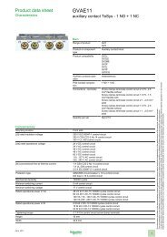
including 1 N.O. + 1 N.C. make-before-break<br />
Contact Arrangement Catalog Number $ Price<br />
1 — LADN10 13.10<br />
— 1 LADN01 13.10<br />
1 1 LADN11 20.70<br />
2 - LADN20 20.70<br />
2 2 LADN22 41.50<br />
1 3 LADN13 41.50<br />
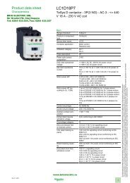
4 — <strong>LADN40</strong> 41.50<br />
— 4 LADN04 41.50<br />
3 1 LADN31 41.50<br />
2 2 b LADC22 41.50<br />
Table 18.14: Accessories—For the assembly of three-pole reversing contactors<br />
(horizontal mounting)<br />
With 2 Identical<br />
Contactors c<br />
Set Of Power Connections<br />
Catalog Number<br />
$ Price<br />
Horizontal Mounting<br />
Mechanical Interlock Kit<br />
Catalog Number<br />
$ Price<br />
LC1F115 LA9FF976 106.00 LA9FF970 53.00<br />
LC1F150 LA9F15076 96.00 LA9FF970 53.00<br />
LC1F185 LA9FG976 113.00 LA9FG970 53.00<br />
LC1F265 LA9FH976 151.00 LA9FJ970 76.00<br />
LC1F330 LA9FJ976 225.00 LA9FJ970 76.00<br />
LC1F400 LA9FJ976 198.00 LA9FJ970 76.00<br />
LC1F500 LA9FK976 306.00 LA9FJ970 76.00<br />
LC1F630, F800 LA9FL976 568.00 LA9FL970 76.00<br />
c For two contactors of different size, refer to pages 18-15.<br />
IEC CONTACTORS AND<br />
18 STARTERS<br />
TeSys F contactor accessories. . . . . . . . . . . . . . . . . . . . . . . . . . . .page 18-11<br />
TeSys F overload relay accessories. . . . . . . . . . . . . . . . . . . . . . . .page 18-16<br />
TeSys F replacement coils and parts . . . . . . . . . . pages 18-13, 18-18, 18-20<br />
Dimensions . . . . . . . . . . . . . . . . . . . . . . . . . . . . . . . . . . . . . . . . . . .page 18-42<br />
E164862<br />
CCN NLDX<br />
LR43364<br />
Class 3211 04<br />
© 2009 Schneider Electric<br />
All Rights Reserved<br />
I12<br />
Discount<br />
Schedule<br />
18-7
Contactor<br />
Accessories<br />
TeSys ® D & F Auxiliary Contacts, Time Delay, Mechanical Latch<br />
Refer to Catalog 8502CT9901<br />
www.schneider-electric.us<br />
IEC CONTACTORS AND<br />
18 STARTERS<br />
Front Mounted<br />
Auxiliary Blocks<br />
(shown on TeSys D<br />
contactor)<br />
Table 18.15: Standard, instantaneous auxiliary contact blocks<br />
a<br />
b<br />
c<br />
d<br />
e<br />
Snap-On<br />
Mounting<br />
To front of<br />
LC●DT20–D258 (4P),<br />
LC●D09–D150a<br />
or<br />
To right side of<br />
LC●F<br />
To front of<br />
LC●D80 and D115<br />
or<br />
To left side of<br />
LC●F<br />
Number of<br />
Contacts<br />
4 a<br />
2<br />
1<br />
Composition<br />
N.O.<br />
N.C.<br />
Catalog Number a<br />
$ Price<br />
2 2 LADN22 b 41.50<br />
1 3 LADN13 b 41.50<br />
4 0 <strong>LADN40</strong> b 41.50<br />
0 4 LADN04 b 41.50<br />
3 1 LADN31 b 41.50<br />
2 c 2 c LADC22 bc 41.50<br />
1 1 LADN11 b 20.70<br />
2 0 LADN20 b 20.70<br />
0 2 LADN02b 20.70<br />
1 0 LADN10 d 13.10<br />
0 1 LADN01 d 13.10<br />
To side of<br />
LC●D09 to D150 only<br />
2 1 1 LAD8N11 e 20.70<br />
(not for use on TeSys F)<br />
2 0 LAD8N20 e 20.70<br />
For low consumption coils (LC1D09 to D32 only), only one front-mounted two-contact block allowed. No sidemounted<br />
contact blocks allowed.<br />
For spring terminal versions of these blocks, add a “3” to the end of the catalog number. (Ex. LADN223). No price<br />
adder for this modification.<br />
Including 1 N.O. + 1 N.C. make before break overlapping contacts.<br />
This block cannot be added to the LC1D 09 to D32 contactors; a maximum of 2 blocks can be mounted on the<br />
LC1D40A to LC1/LP1D80 contactors only.<br />
1 block may be added to the left side of the LC1D 09 to D32, AC coils only; 1 block may be added to each side of<br />
the LC1D 40A to D80 contactors, AC coils only. Cannot be installed on TeSys D contactors with DC coils.<br />
Table 18.16: Instantaneous blocks with dust-tight auxiliary contacts (IP54)<br />
NEMA 12<br />
Snap-On<br />
Mounting<br />
To front of<br />
LP●D40–D80, LC●DT20–D258 (4P),<br />
LC●D09 to D80<br />
or<br />
To right side of<br />
LC●F<br />
f<br />
Device supplied with 4 ground terminal points.<br />
Standard Contacts Dusttight Contacts<br />
N.O. N.C. N.O. N.C.<br />
Table 18.17: Pneumatic time delay contact blocks<br />
Snap-On<br />
Mounting<br />
To front of<br />
LP●D40–D80,<br />
LC●DT20–D258 (4P),<br />
LC●D09 to D150<br />
or<br />
To right side of<br />
LC●F<br />
Time Delay<br />
Contacts<br />
N.O. N.C.<br />
1 1<br />
1 1<br />
Catalog Number<br />
$ Price<br />
— — 2 — LA1DX20 65.00<br />
2 — 2 — LA1DZ40 82.00<br />
1 1 2 — LA1DZ31 82.00<br />
— — 2 — LA1DY20f 77.00<br />
Type<br />
On energization<br />
(on delay)<br />
On de-energization<br />
(off-delay)<br />
Range of<br />
Time Delay<br />
Catalog<br />
Number h<br />
$ Price<br />
0.1 to 3 sg LADT0 131.00<br />
0.1 to 30 s LADT2 131.00<br />
10 to 180 s LADT4 131.00<br />
1 to 30 si LADS2 131.00<br />
0.1 to 3 sg LADR0 131.00<br />
0.1 to 30 s LADR2 131.00<br />
10 to 180 s LADR4 131.00<br />
g Scale range is expanded between 0.1 and 0.6 seconds on the dial for more accurate settings at the lower end of<br />
the range.<br />
h For spring terminal versions of these blocks, add a “3” to the end of the catalog number. (Ex. LADT23). No price<br />
adder for this modification.<br />
i With switching time of 40 ms ± 15 ms between the opening of the N.C. contact to the closing of the N.O. contact.<br />
Table 18.18: Mechanical latch blocks with manual or electrical unlatch<br />
(TeSys D only)<br />
Front snap-on<br />
mounting onto<br />
Application<br />
Catalog number<br />
to be completed<br />
by the code corresponding<br />
to the coil voltage<br />
$ Price<br />
LC●D09 to D65A<br />
For silent operation and energy<br />
conservation<br />
LAD6K10jk 77.00<br />
LC1 D80 to D150 LP1 D80<br />
For silent operation and energy<br />
conservation<br />
LA6DK20jk 77.00<br />
j Does not include internal coil clearing contact.<br />
k Complete catalog number by adding coil voltage code. For example: LAD6K10F.<br />
Table 18.19: Coil Voltage Codes for LA6DK mechanical latch blocks<br />
Volts 12 24 32/36 42/48 60/72 100<br />
AC or DC J B C E EN K F L M Q R S<br />
110/<br />
127<br />
200/<br />
208<br />
220/<br />
240<br />
380/<br />
415<br />
440/<br />
480<br />
500/<br />
600<br />
E164862<br />
CCN NLDX<br />
LR43364<br />
Class 3211 04<br />
TeSys D contactors . . . . . . . . . . . . . . . . . . . . . . . . . . . . . . . .pages 18-4, 18-6<br />
TeSys D overload relay accessories . . . . . . . . . . . . . . . . . . . . . . . page 18-16<br />
TeSys D replacement coils . . . . . . . . . . . . . . . . . . . . . . pages 18-18 to 18-19<br />
Dimensions. . . . . . . . . . . . . . . . . . . . . . . . . . . . . . . . . . . pages 18-40 to 18-46<br />
18-8 © 2009 Schneider Electric<br />
I12 Discount<br />
Schedule<br />
All Rights Reserved
www.schneider-electric.us<br />
LA4DA1U<br />
LA4DA2U<br />
LA4DC3U<br />
LAD4BB• •<br />
© 2009 Schneider Electric<br />
All Rights Reserved<br />
Contactor Accessories<br />
TeSys ® D Coil Suppressors, Cabling Accessories<br />
Refer to Catalog 8502CT9901<br />
RC Coil Suppressor<br />
• Limitation of transient voltage to 300% of nominal voltage maximum<br />
• Oscillating frequency limited to 400 Hz maximum. Slight increase in drop-out time (1.2 to 2 times normal)<br />
Table 18.20: Resistor/capacitor circuit (RC) for reduction of “electrical noise” in AC contactor coils<br />
Installed by Mounting on Operating voltage 50/60 Hz Catalog Number $ Price<br />
Snapping into cavity on right side without toolsb<br />
Snap-on mounting and connection without tools to the<br />
contactor coil terminals<br />
Screw connection to the contactor coil terminals<br />
LC1D09 to LC1D32 (3P)<br />
LC●DT20 to DT40 (4P),<br />
LC1D40A to LC1D65A (3P),<br />
LC1DT60A to LC1DT80A<br />
(4P)<br />
LC●D80 to D150 (3 or 4P)<br />
LC●D80 to D115 (4P)<br />
Varistor Coil Suppressor<br />
• Limitation of transient voltage value to 200% of nominal voltage maximum<br />
• Maximum reduction of transient voltage peaks. Slight increase in drop-out time (1.1 to 1.5 times normal)<br />
Diode Coil Suppressor<br />
• No overvoltage or oscillating frequency<br />
• Polarized component. Increased drop-out time (6 to 10 times normal)<br />
Bidirectional Diode Coil Suppressor<br />
• Protection provided by limiting the transient voltage to 2 Uc max.<br />
• Maximum reduction of transient voltage peaks<br />
TeSys D contactors . . . . . . . . . . . . . . . . . . . . . . . . . . . . . . . . pages 18-4, 18-6<br />
TeSys D overload relay accessories. . . . . . . . . . . . . . . . . . . . . . . .page 18-16<br />
TeSys D replacement coils . . . . . . . . . . . . . . . . . . . . . . pages 18-18 to 18-19<br />
Dimensions . . . . . . . . . . . . . . . . . . . . . . . . . . . . . . . . . . pages 18-40 to 18-46<br />
24–28 V LAD4RCE 26.20<br />
50–127 V LAD4RCG 26.20<br />
110–240 V LAD4RCU 26.20<br />
24-48 V LAD4RC3E 26.20<br />
50-127 V LAD4RC3G 26.20<br />
110-240 V LAD4RC3U 26.20<br />
380-415 V LAD4RC3N 26.20<br />
24–48 V LA4DA2E 26.20<br />
50–127 V LA4DA2G 26.20<br />
110–240 V LA4DA2U 26.20<br />
380–415 V LA4DA2N 26.20<br />
Table 18.21: Varistor (peak limiting) for reduction of “electrical noise” in AC or DC contactor coils<br />
Installed by Mounting on Operating voltage 50/60 Hz Catalog Number $ Price<br />
Snapping into cavity on right side without toolsb<br />
Snap-on mounting and connection without tools to the<br />
contactor coil terminals<br />
Screw connection to the contactor coil terminals<br />
LC●D09 to D32a<br />
TeSys D contactors<br />
LC1D40A to LC1D65A (3P),<br />
LC1DT60A to LC1DT80A<br />
(4P)<br />
LC●D80 to D115 (3P or 4P)<br />
LC●D12, D25 (4P)<br />
Screw connection to the contactor coil terminals LC●D80 (3P or 4P)<br />
a<br />
For DC coils 3-pole contactors are fitted with built-in surge suppression as standard.<br />
Table 18.22: Diode for reduction of “electrical noise” in DC contactor coils<br />
24–48 V LAD4VE 26.20<br />
50–127 V LAD4VG 26.20<br />
110–250 V LAD4VU 26.20<br />
24-48 V LAD4V3E 26.20<br />
50-127 V LAD4V3G 26.20<br />
110-250 V LAD4V3U 26.20<br />
24–48 Vac LA4DE2E 26.20<br />
50–127 Vac LA4DE2G 26.20<br />
110–250 Vac LA4DE2U 26.20<br />
24–48 Vdc LA4DE3E 26.20<br />
50–127 Vdc LA4DE3G 26.20<br />
110–250 Vdc LA4DE3U 26.20<br />
Installed on the upper part by Mounting on Operating voltage DC Catalog Number $ Price<br />
Snap-on mounting and connection w/o tools to the contactor coil terminals LC●D09 - D32 24–250 V LAD4DDL 26.20<br />
Clip-on front mounting<br />
LC●D40A to D65,<br />
D65A to DT80A<br />
24–250 V LAD4D3U 26.20<br />
Screw connection of wire to the contactor coil terminals<br />
D80 (3P)<br />
D80 (4P)<br />
24–250 V LA4DC3U 26.20<br />
Table 18.23: Bidirectional peak limiting diode<br />
Installed by Mounting on Operating Voltage 50/60 Hz and DC Catalog Number $ Price<br />
Snapping into cavity on right side of contactor b<br />
LC●D09 to LC●D32 (3P)c<br />
24 (AC only) LAD4TB 26.20<br />
DT20 to DT40 (4P)<br />
72 (AC only) LAD4TS 26.20<br />
12 - 24 V LAD4T3B 26.20<br />
Clip-on front mounting and connection without tools<br />
LC1D40A to LC1D65A (3P),<br />
25 - 72 V LAD4T3S 26.20<br />
to the contactor coil terminals c<br />
LC1DT60A to LC1DT80A<br />
73 - 125 V LAD4T3G 26.20<br />
(4P)<br />
126 - 250 V LAD4T3U 26.20<br />
251 - 440 V LAD4T3R 26.20<br />
24 (AC only) LA4DB2B 56.00<br />
Screw Mounting d<br />
LC●D80<br />
72 (AC only) LA4DB2S 26.20<br />
24 (DC only) LA4DB3B 56.00<br />
72 (DC only) LA4DB3S 56.00<br />
b Installing suppressor into the cavity makes the electrical connection. Overall width of contactor remains the same.<br />
c For LC●D09 through LC●D65A with DC or low consumption DC coils, 3-pole contactors are fitted with built-in bidirectional diode suppression as<br />
standard.<br />
d Mounting at the top of the contactor on coil terminals A1 and A2.<br />
Table 18.24: Cabling Accessories<br />
Usage Mounting on Operating voltage 50/60 Hz Catalog Number $ Price<br />
For adapting existing wiring to a new product or for use with<br />
top mount accessory.<br />
For adapting existing wiring to a new product or for use with<br />
top mount accessory<br />
I12<br />
Discount<br />
Schedule<br />
LC1D09 to D38<br />
LC1DT20 to DT60<br />
AC only<br />
LC1D40A to LC1D65A<br />
(with no coil suppressor)<br />
Without coil suppression LAD4BB 23.00<br />
With coil 24-48 V LAD4BBVE 23.00<br />
suppression 50-127 V LAD4BBVG 23.00<br />
(varistor) 110-250 V LAD4BBVU 23.00<br />
— LAD4BB3 26.20<br />
18-9<br />
IEC CONTACTORS AND<br />
18 STARTERS
IEC CONTACTORS AND<br />
18 STARTERS<br />
Contactor Accessories<br />
LA4DFB<br />
www.schneider-electric.us<br />
The following accessories require use of cabling accessories (LAD4BB●●) for proper mounting. See page 18-9 for<br />
illustration.<br />
Electronic Serial Timer Modules<br />
These solid state modules delay the energizing and de-energizing of the contactor coil.<br />
Table 18.25:<br />
Type<br />
24–250 Vac<br />
Operational Voltage a<br />
100–250 Vac<br />
Time Delay Catalog Number $ Price<br />
0.1–2 s LA4DT0U 82.<br />
On-delay LC1D09–D65A LC1D80–D150<br />
1.5–30 s LA4DT2U 82.<br />
25–500 s LA4DT4U 82.<br />
a For 24 V operation, the contactor must be fitted with a 21 V coil: coil voltage code Z5 for 50 Hz; Z6 for 60 Hz; ZD for DC.<br />
Interface Modules b<br />
These modules allow the contactor coils to be energized from low voltage and low current level signals. They come in<br />
mechanical relay and solid state versions. The relay plus manual operation versions include a lever for manually<br />
turning the contactor on and off. When a module receives a low level signal, it allows the separate sourced control<br />
voltage to flow to the contactor coil. It saves space and wiring time compared to conventional interposing relays.<br />
Table 18.26:<br />
Interface Type<br />
Operational Voltage<br />
24–250 Vac 100–250 Vac<br />
Input Voltage Catalog Number $ Price<br />
Relay<br />
LC1D09–D150 24 Vdc LA4DFB 55.<br />
LC1D09–D150 48 Vdc LA4DFE 55.<br />
Relay Plus LC1D09–D150 24 Vdc LA4DLB 71.<br />
Manual Operation LC1D09–D150 48 Vdc LA4DLE 71.<br />
Solid State LC1D09–D65 LC1D80–D115 24 Vdc LA4DWB 71.<br />
b Adapter required for D09 - D65A, see table 18.24.<br />
Automatic-Manual-Stop Control Modules<br />
These modules allow for local and/or remote operation of the contactor coil. Each module includes a lever to switch<br />
from automatic to manual operation and a dial to turn the contactor on and off.<br />
Table 18.27:<br />
Operational Voltage<br />
24–100 Vac 100–250 Vac<br />
Catalog Number $ Price<br />
LC1D09–D150 — LA4DMK 35.<br />
Low Voltage Ride Through Module (meets SEMI F47 requirements)<br />
By ensuring SEMI F47 compliance of AC powered IEC contactors and relays, the low voltage ride through modules can<br />
be used to increase the voltage sag immunity of semiconductor processing equipment. These modules make it<br />
possible for AC powered <strong>Telemecanique</strong> contactors and relays to exceed the requirements of SEMI F47, both in the<br />
magnitude and duration of a voltage sag event—even with accessories such as auxiliary contact blocks and pneumatic<br />
timers.<br />
The low voltage ride through modules can be used with <strong>Telemecanique</strong> contactors from 9 A through 80 A, as well as<br />
the CAD series of control relays<br />
Table 18.28:<br />
TeSys ® D Electronic Timers and Interface Modules<br />
Refer to Catalog 8502CT9901<br />
For use on:<br />
Contactor<br />
Relay<br />
Catalog Number<br />
$ Price<br />
LC1D●●B7 CAD●●B7 LADLVRT24V c 124.<br />
LC1D●●G7 CAD●●G7 LADLVRT120V c 124.<br />
LC1D●●LE7 CAD●●LE7 LADLVRT208V c 124.<br />
Top mount bracket (required when using above modules) D09 - D32 LAD4BB c 23.<br />
Top mount bracket (required when using above modules) D40 - D65 LAD4BB3 c 23.<br />
Fuse LA9D941 120.<br />
c LAD4BB must be used when the low voltage ride through module is being used with contactors 32 A and less, and TeSys CAD Series of Control Relays.<br />
The LAD4BB3 must be used with the D40 - D65A. See table 18.24 on page 18-10.<br />
TeSys D contactors . . . . . . . . . . . . . . . . . . . . . . . . . . . . . . . .pages 18-4, 18-6<br />
TeSys D overload relay accessories . . . . . . . . . . . . . . . . . . . . . . . page 18-16<br />
TeSys D replacement coils. . . . . . . . . . . . . . . . . . . . . . . pages 18-18 to 18-19<br />
Dimensions. . . . . . . . . . . . . . . . . . . . . . . . . . . . . . . . . . . pages 18-40 to 18-46<br />
LADLVRT<br />
A1<br />
E1<br />
E2<br />
1.85<br />
47<br />
A2<br />
A1<br />
A2<br />
LADLVRT<br />
A1<br />
E1<br />
E2<br />
1.25<br />
32<br />
A2<br />
LAD4BB<br />
Contactors 32 A and less<br />
Contactors 40 A–80 A<br />
18-10 © 2009 Schneider Electric<br />
I12 Discount<br />
Schedule<br />
All Rights Reserved
www.schneider-electric.us<br />
Contactor Accessories<br />
TeSys ® D and F Accessories<br />
Refer to Catalog 8502CT9901<br />
LA9D1260<br />
LA9D2561<br />
LA9D40961<br />
LA9D6567<br />
Table 18.29: For Power Pole or Control Connection<br />
Connectors for<br />
larger cable sizes<br />
Everlink® terminal<br />
block<br />
Links<br />
for the parallel<br />
connection of<br />
Description<br />
For use with<br />
contactors<br />
LC1/LP1<br />
Sold in<br />
lots of<br />
Catalog<br />
Number<br />
$ Price each<br />
4 poles #8 AWG (10 mm 2 ) D09, D12 1 LAD92560 8.70<br />
3 poles #4 AWG (25 mm 2 ) D09–D32 1 LA9D3260 12.00<br />
3 poles D40A-D65A 1 LAD96560 10.00<br />
2 poles<br />
3 poles<br />
(Wye-Delta<br />
Shorting Strap)<br />
4 poles<br />
D09–D32 10 LA9D2561 26.20<br />
D40A–D65A 1 LAD9P32 6.00<br />
D80 2 LA9D80961 6.50<br />
F115 4 LA9FF602 55.00<br />
F150, F185 4 LA9FG602 65.00<br />
F265, F330, F400 4 LA9FH602 169.00<br />
F500 4 LA9FK602 228.00<br />
F630, F800 4 LA9FL602 278.00<br />
D09–D32 10 LAD9P3 10.00<br />
D40A-D65A 1 LAD9P33 25.00<br />
D80 1 LA9D80962 6.50<br />
F115 1 LA9FF601 6.80<br />
F150, F185 1 LA9FG601 8.20<br />
F265, F330, F400 1 LA9FH601 12.00<br />
F500 1 LA9FK601 21.80<br />
F630, F800 1 LA9FL601 38.20<br />
DT20, DT25 2 LA9D1263 8.70<br />
D80 2 LA9D80963 17.50<br />
Second coil connection LP1D40–D80 10 LA9D09966 2.20<br />
D115, D150 10 LA9D11567 4.00<br />
Control circuit take-off from main pole<br />
D80 10 LA9D8067 5.50<br />
Spreaders for increasing pole pitch to 45 mm D115, D150 3 GV7AC03 31.10<br />
Table 18.30: For Marking<br />
Description<br />
For use with<br />
contactors<br />
LC1/LP1<br />
Sold in<br />
lots of<br />
Catalog<br />
Number<br />
$ Price each<br />
Reference label holder snap-on 8 x 22 mm<br />
4-pole contactors<br />
D80 - D115<br />
100 LA9D92 .06<br />
Reference label holder snap-on 8 x 18 mm 3 poles<br />
D09-D65A, DT20-DT80A,<br />
LADN, LADT, LADR<br />
100 LAD90 .06<br />
Sheet of 300 labels self adhesive 7 x 21 mm For holder LA9D92 1 LA9D93 4.30<br />
Table 18.31: For Mounting<br />
Description<br />
For use with<br />
contactors<br />
LC1/LP1<br />
Sold in<br />
lots of<br />
Catalog<br />
Number<br />
$ Price each<br />
Set of shims for mounting LAD8N and LA8DN D80 1 LA9D511 9.80<br />
Retrofit plate for replacement of LC1D40-D65 with<br />
LC1D40A-D65A<br />
D40A-D65A 1 LAD7X3 25.00<br />
35 mm DIN Rail – 2 meters long LC1D09 to D80 10 AM1DP200 5.20<br />
Table 18.32: Replacement contacts<br />
For use with<br />
contactors<br />
Catalog<br />
Number<br />
LC1D115 3 poles LA5D1158031 239.00<br />
Three-pole<br />
LC1D150 3 poles LA5D150803 239.00<br />
Four-pole LC1D115 4 poles LA5D115804 318.00<br />
Table 18.33: Arc chambers<br />
For use with<br />
contactors<br />
Catalog<br />
Number<br />
LC1D115 3 poles LA5D11550 90.00<br />
Three-pole<br />
LC1D150 3 poles LA5D15050 90.00<br />
Four-pole LC1D115 4 poles LA5D115450 119.00<br />
$ Price<br />
$ Price<br />
IEC CONTACTORS AND<br />
18 STARTERS<br />
TeSys D contactors . . . . . . . . . . . . . . . . . . . . . . . . . . . . . . . . pages 18-4, 18-6<br />
TeSys D overload relay accessories. . . . . . . . . . . . . . . . . . . . . . . .page 18-16<br />
TeSys D replacement coils . . . . . . . . . . . . . . . . . . . . . . pages 18-18 to 18-19<br />
Dimensions . . . . . . . . . . . . . . . . . . . . . . . . . . . . . . . . . . pages 18-40 to 18-47<br />
TeSys F contactors . . . . . . . . . . . . . . . . . . . . . . . . . . . . . . . . pages 18-5, 18-7<br />
TeSys F replacement coils and parts . . . . . . . . . . pages 18-13, 18-18, 18-20<br />
LA9D511<br />
© 2009 Schneider Electric<br />
All Rights Reserved<br />
I12<br />
Discount<br />
Schedule<br />
18-11
Contactor Accessories<br />
LA9D09981<br />
Table 18.34: Suppressor Blocks<br />
TeSys ® F Contactors<br />
Refer to Catalog 8502CT9901<br />
www.schneider-electric.us<br />
Operating limit: up to 220 V, 50/60 Hz coils<br />
Description For Use Catalog Number $ Price<br />
With coils LX1FF, FG, FH, F115, F150, F185, F225, F265, F330 LA9F980 21.80<br />
Suppressor block<br />
(clip-on mounting to coil) With coils<br />
LX1FJ, FK, FL, FX, F400, F500, F630, F780, LX9FF, FG, FH, F115, F150, F185, F225,<br />
F265, F330<br />
LA9D09980 20.70<br />
Mounting bracket (for 35 mm DIN rail or panel mounting) for suppressor block LA9D09981 5.50<br />
IEC CONTACTORS AND<br />
18 STARTERS<br />
LA9F980<br />
Table 18.35: Lugs and Lug Kits a<br />
Contactor<br />
Lug Kit Catalog<br />
Type LC1<br />
Number<br />
Contactor Only<br />
Cable Size AWG<br />
range<br />
Overload Relay<br />
Directly<br />
mounted to<br />
contactor<br />
LC1•<br />
Lugs Required<br />
Cable size AWG range<br />
Line side of<br />
contactor<br />
Load side of<br />
overload<br />
Line side of<br />
contactor<br />
Load side of<br />
overload<br />
F115 DZ2FF6 14 to 2/0 LR9F5•57 to F5•69 F115 3 each DZ2FF1 3 each DZ2FG1 14 to 2/0 6 to 3/0<br />
F150, F185 DZ2FG6 6 to 3/0 LR9F5•57 to F5•71 F150 to F185 1 each DZ2FG6 6 to 3/0<br />
— LR9F5•71 F225, F265 1 each DZ2FH6 6 to 300 MCM<br />
F225, F265,<br />
F330<br />
DZ2FH6 6 to 300 MCM LR9F7•75 to F7•79 F265 or F330 3 each DZ2FH1 6 to 300 MCM 4 to 500 MCM<br />
F400 DZ2FJ6 4 to 500 MCM LR9F7•75 to F7•81 F400 3 each DZ2FJ1 4 to 500 MCM 4 to 500 MCM<br />
F500 DZ2FK6 2 x 2 to 600 MCM LR9F7•75 to F7•81 F500 3 each DZ2FK1 2x2 to 600 MCM 4 to 500 MCM<br />
F630, F800 DZ2FL6 3 x 2 to 600 MCM LR9F7•81 F630<br />
1 each DZ2FL1<br />
DZ2FL2<br />
DZ2FL3<br />
1 each DZ2FR1 3x2 to 600 MCM 4 to 500 MCM<br />
F780 DZ2FX6 4 x 1/0 to 750 MCM — — — —<br />
a Lug kits ending in the number “6” include 6 identical lugs. In some cases the LR9F overload relay mounted directly on the load side of an LC1F contactor<br />
will require a different size lug for your choice of contactor and overload. If the two sizes are different, order 3 of each size lug. Mounting hardware (screws,<br />
washers, and nuts) are provided with the contactors and overload relays, not with the lugs. See Table 18.37 for pricing.<br />
Table 18.36: Lugs—2 and 4-Pole c<br />
b<br />
c<br />
Contactor<br />
Type LC1<br />
Lug Kit<br />
Catalog Number<br />
Qty. Required<br />
AL/CU<br />
Cable Size<br />
F115 DZ2FF1 4 8 14 to 2/0<br />
F150, F185 DZ2FG1 4 8 6 to 3/0<br />
F225, F265, F330 DZ2FH1 4 8 6 to 300 MCM<br />
F400 DZ2FJ1 4 8 4 to 500 MCM<br />
F500 DZ2FK1 4 8 2 X 2 to 600 MCM<br />
F630 DZ2FLb b b 3 X 2 to 600 MCM<br />
F780 DZ2FX1 4 8 4 X 1/0 to 750 MCM<br />
For 2-pole F630 contactors, order 2 DZ2FL1 (L1 and T2), and 2 DZ2FL3 (L2 and T1).<br />
For 4-pole F6304, order 2 DZ2FL1 (L1 and T4), 4 DZ2FL2 (L2, T2, L3, T3) and 2 DZ2FL3 (L4 and T1).<br />
Lugs for LC1F contactors and overload relays must be ordered separately. Each kit consists of one (1) lug. Mounting hardware (screws, washers, nuts)<br />
are provided with the contactors, not the lugs. See Table 18.37 for pricing.<br />
Table 18.37: Lugs Pricing<br />
Lug Catalog Number $ Price Lug Catalog Number $ Price<br />
DZ2FF6 39.30 DZ2FH1 11.00<br />
DZ2FG6 65.00 DZ2FJ1 11.00<br />
DZ2FH6 65.00 DZ2FK1 21.80<br />
DZ2FJ6 65.00 DZ2FL1 27.30<br />
DZ2FK6 131.00 DZ2FL2 55.00<br />
DZ2FL6 164.00 DZ2FL3 27.30<br />
DZ2FX6 163.80 DZ2FR1 173.30<br />
DZ2FF1 6.50 DZ2FX1 27.30<br />
DZ2FG1 11.00<br />
These clear plastic protective shrouds are an effective means to meet international touch-safe requirements for power<br />
terminals. They are designed to be used with power cables that have been bolted to the terminal.<br />
NOTE: The protection shrouds do not attach to contactors or overloads utilizing DZ2F lug kits.<br />
2-Pole<br />
4-Pole<br />
LA9F70•<br />
Table 18.38: Power Terminal Protection Shrouds<br />
For Use With 2-, 3-, And 4-pole Contactors<br />
Number of Shrouds<br />
Per Set<br />
Catalog Number<br />
$ Price<br />
LC1F115 6 LA9F701 42.40<br />
LC1F150, F185 6 LA9F702 61.00<br />
LC1F225, F265, F330, F400 and F4002, F500 and F5002 6 LA9F703 82.00<br />
LC1F630, F6302 and F800 6 LA9F704 93.00<br />
LC1F1154 8 LA9F706 58.00<br />
LC1F1504 and F1854 8 LA9F707 80.00<br />
LC1F2254, F2654, F3304, F4004, F5004 8 LA9F708 111.00<br />
LC1F6304 8 LA9F709 120.00<br />
For contactors LC1F115, LC1F150, and LC1F185, an available touch-safe terminal block may be used in place of lugs<br />
for power connections.<br />
Table 18.39: Insulated Terminal Blocks<br />
For contactor<br />
type LC1<br />
For overload<br />
relay LR9<br />
Maximum<br />
Cable Size<br />
Catalog Number<br />
$ Price<br />
F115, F150, F185 F5•57, F5•63, F5•67, F5•69 300 MCM LA9F103 55.00<br />
TeSys F contactors . . . . . . . . . . . . . . . . . . . . . . . . . . . . . . . .pages 18-5, 18-7<br />
TeSys F overload relay accessories . . . . . . . . . . . . . . . . . . . . . . . page 18-16<br />
TeSys F replacement coils and parts . . . . . . . . . .pages 18-18, 18-18, 18-20<br />
Dimensions. . . . . . . . . . . . . . . . . . . . . . . . . . . . . . . . . . . pages 18-40 to 18-47<br />
18-12 © 2009 Schneider Electric<br />
I12 Discount<br />
Schedule<br />
All Rights Reserved
www.schneider-electric.us<br />
Replacement Parts<br />
TeSys ® F Contact Kits, Arc Chambers<br />
Refer to Catalog 8502CT9901<br />
LA5FG431<br />
LA5F11550<br />
Table 18.40: Replacement contact sets a<br />
For use on contactors Catalog Number $ Price<br />
Two-pole<br />
Three-pole<br />
Four-pole<br />
Table 18.41: Arc chambers<br />
a<br />
b<br />
c<br />
d<br />
Two-pole<br />
Three-pole<br />
Four-pole<br />
LC1F4002 2 poles LA5F400802 717.<br />
LC1F5002 2 poles LA5F500802 1111.<br />
LC1F6302 2 poles LA5F630802 1651.<br />
LC1F115, F150 3 poles LA5FF431 239.<br />
LC1F185 3 poles LA5FG431 418.<br />
LC1F265 3 poles LA5FH431 793.<br />
LC1F330, F400 3 poles LA5F400803 1076.<br />
LC1F500 3 poles LA5F500803 1589.<br />
LC1F630 3 poles LA5F630803 2488.<br />
LC1F780 1 pole LA5F780801d 1651.<br />
LC1F800 3 poles LA5F800803 2488.<br />
LC1F1504, F1154 4 poles LA5FF441 318.<br />
LC1F1854 4 poles LA5FG441 549.<br />
LC1F2654 4 poles LA5FH441 966.<br />
LC1F3304, F400, F4004 4 poles LA5F400804 1435.<br />
LC1F5004 4 poles LA5F500804 2461.<br />
LC1F6304 4 poles LA5F630804 3304.<br />
LC1F7804 1 pole LA5F780801d 1651.<br />
For use on contactors Catalog Number $ Price<br />
LC1F4002 2 poles LA5F400250 280.<br />
LC1F5002 2 poles LA5F500250 305.<br />
LC1F6302 2 poles LA5F630250 431.<br />
LC1F115 3 poles LA5F11550 90.<br />
LC1F150 3 poles LA5F15050 101.<br />
LC1F185 3 poles LA5F18550 179.<br />
LC1F265 3 poles LA5F26550 269.<br />
LC1F330 3 poles LA5F33050 287.<br />
LC1F400 3 poles LA5F40050 305.<br />
LC1F500 3 poles LA5F50050 341.<br />
LC1F630 3 poles LA5F63050 646.<br />
LC1F780 1 pole LA5F780150d 431.<br />
LC1F800 3 poles LA5F80050 750.<br />
LC1F1154 4 poles LA5F115450 119.<br />
LC1F1504 4 poles LA5F150450 131.<br />
LC1F1854 4 poles LA5F185450 248.<br />
LC1F2654 4 poles LA5F265450 299.<br />
LC1F3304 4 poles LA5F330450 414.<br />
LC1F4004 4 poles LA5F400450c 573.<br />
LC1F5004 4 poles LA5F500450c 610.<br />
LC1F6304 4 poles LA5F630450b 861.<br />
LC1F7804 1 pole LA5F780150d 431.<br />
Supplied per pole are: 2 fixed contacts, 1 moving contact, 2 deflectors, 1 backplate, mounting screws and washers.<br />
Comprises single-pole components.<br />
Comprises 2-pole components.<br />
2 identical components per pole are supplied.<br />
IEC CONTACTORS AND<br />
18 STARTERS<br />
TeSys F contactors . . . . . . . . . . . . . . . . . . . . . . . . . . . . . . . . pages 18-5, 18-7<br />
TeSys F overload relay accessories . . . . . . . . . . . . . . . . . . . . . . . .page 18-16<br />
TeSys F replacement coils and parts . . . . . . . . . . pages 18-13, 18-18, 18-20<br />
Dimensions . . . . . . . . . . . . . . . . . . . . . . . . . . . . . . . . . . pages 18-42 to 18-47<br />
© 2009 Schneider Electric<br />
All Rights Reserved<br />
I12<br />
Discount<br />
Schedule<br />
18-13
Contactors Accessories<br />
TeSys ® D Reversing Contactors<br />
Refer to Catalog 8502CT9901<br />
www.schneider-electric.us<br />
Table 18.42: Contactors Mechanical interlock Set of power connections<br />
Reversing contactors comprising two identical,<br />
horizontally mounted contactors:<br />
Without electrical<br />
interlock<br />
With incorporated<br />
electrical interlock<br />
(2 N.C. contacts)<br />
Reversing contactors<br />
for motor control<br />
Four pole<br />
contactors<br />
Catalog<br />
Number<br />
$ Price Catalog Number $ Price Catalog Number $ Price Catalog Number $ Price<br />
LC1D09, LC1D12, LC1D18, LC1D25, LC1D32 LAD9R1e 32.10 LAD9R1Ve 45.50 Included with kit Not Available<br />
LC1DT20, LC1DT25, LC1DT32, LC1DT40 LADT9R1e 36.90 LADT9R1Ve 45.50 Not Available Included with kit<br />
e Kit including mechanical interlock and wiring.<br />
IEC CONTACTORS AND<br />
18 STARTERS<br />
LC1D40, LC1D50, LC1D/LP1D65 LA9D50978 31.70 LA9D4002 45.90 LA9D6569 53.00 LA9D6570 63.00<br />
LC1D40A, D50A, D65A LAD4CM 45.00 Not Available LA9D65A69 75.00 Not Available<br />
LC1D80 AC coil LA9D50978 31.70 LA9D4002 45.90 LA9D8069 65.00 LA9D8070 79.00<br />
LC1D80 DC coil LA9D80978 31.70 LA9D8002 65.00 LA9D8069 65.00 LA9D8070 79.00<br />
LC1D115 and LC1D150 Not Available LA9D11502 78.00 LA9D11569 129.00<br />
LA9D11571<br />
(3P)<br />
LA9D11570<br />
(4P) (D115 only)<br />
53.00<br />
53.00<br />
TeSys D contactors . . . . . . . . . . . . . . . . . . . . . . . . . . . . . . . .pages 18-4, 18-6<br />
TeSys D overload relay accessories . . . . . . . . . . . . . . . . . . . . . . . page 18-16<br />
TeSys D replacement coils. . . . . . . . . . . . . . . . . . . . . . . pages 18-17 to 18-19<br />
Dimensions. . . . . . . . . . . . . . . . . . . . . . . . . . . . . . . . . . . pages 18-40 to 18-46<br />
18-14 © 2009 Schneider Electric<br />
I12 Discount<br />
Schedule<br />
All Rights Reserved
www.schneider-electric.us<br />
Contactors Accessories<br />
TeSys ® F Reversing Contactors<br />
Refer to Catalog 8502CT9901<br />
LA9F•970<br />
LA9F•977<br />
LA9F•976<br />
LA9F•4•<br />
Table 18.43: Component parts for the assembly of F-Line 3-pole reversing<br />
contactors<br />
With<br />
2 Identical<br />
Contactors a<br />
Horizontal Mounting<br />
Set of Power Connections<br />
Catalog Number<br />
$ Price<br />
Mechanical Interlock Kit<br />
Catalog Number<br />
$ Price<br />
LC1F115 LA9FF976 106.00 LA9FF970 53.00<br />
LC1F150 LA9F15076 96.00 LA9FF970 53.00<br />
LC1F185 LA9FG976 113.00 LA9FG970 53.00<br />
LC1F265 LA9FH976 151.00 LA9FJ970 76.00<br />
LC1F330 LA9FJ976 225.00 LA9FJ970 76.00<br />
LC1F400 LA9FJ976 225.00 LA9FJ970 76.00<br />
LC1F500 LA9FK976 306.00 LA9FJ970 76.00<br />
LC1F630 or F800 LA9FL976 568.00 LA9FL970 76.00<br />
Vertical Mounting<br />
LC1F115 or F150 d — LA9FF4F 97.00<br />
LC1F185 d — LA9FG4G 113.00<br />
LC1F265 d — LA9FH4H 126.00<br />
LC1F330 d — LA9FJ4J 149.00<br />
LC1F400 d — LA9FJ4J 149.00<br />
LC1F500 d — LA9FK4K 149.00<br />
LC1F630 or F800 d — LA9FL4L 149.00<br />
LC1F780 b — LA9FX970 b 508.00<br />
Table 18.44:<br />
Horizontal<br />
Mounting<br />
Component parts for the assembly of TeSys F 3-pole or 4-pole transfer<br />
contactors<br />
Set of Power Connections<br />
Three-Pole<br />
Four-Pole<br />
$ Price<br />
Mechanical<br />
Interlock Kit<br />
Catalog Number<br />
$ Price<br />
LC1F115/4 LA9FF982 LA9FF977 53.00 LA9FF970 53.00<br />
LC1F150/4 LA9F15082 LA9F15077 53.00 LA9FF970 53.00<br />
LC1F185/4 LA9FG982 LA9FG977 53.00 LA9FG970 53.00<br />
LC1F265/4 LA9FH982 LA9FH977 83.00 LA9FJ970 76.00<br />
LC1F330/4 LA9FJ982 LA9FJ977 113.00 LA9FJ970 76.00<br />
LC1F400/4 LA9FJ982 LA9FJ977 113.00 LA9FJ970 76.00<br />
LC1F500/4 LA9FK982 LA9FK977 154.00 LA9FJ970 76.00<br />
LC1F630/4 LA9FL982 LA9FL977 233.00 LA9FL970 76.00<br />
Vertical Mounting<br />
LC1F115/4 d d — LA9FF4F 97.00<br />
LC1F185/4 d d — LA9FG4G 113.00<br />
LC1F265/4 d d — LA9FH4H 149.00<br />
LC1F330/4 d d — LA9FJ4J 149.00<br />
LC1F400/4 d d — LA9FJ4J 149.00<br />
LC1F500/4 d d — LA9FK4K 149.00<br />
LC1F630/4 d d — LA9FL4L 149.00<br />
LC1F780/4 b c — LA9FX970 c 508.00<br />
IEC CONTACTORS AND<br />
18 STARTERS<br />
A1<br />
A2<br />
LA9FX970<br />
1N 1L2 2L1 2L3<br />
1L3 1L1 2L2 2N<br />
1 3 5 7 1 3 5 7<br />
2 4 6 8 2 4 6 8<br />
A1<br />
A2<br />
L1 L2 L3<br />
1 3 5 1 3 5<br />
2 4 6 2 4 6<br />
A1<br />
A2<br />
U V W<br />
Reversing (motors) Application<br />
A1<br />
A2<br />
Table 18.45: Vertical mounting of 2 contactors of different ratings a<br />
Upper Contactor<br />
Lower Contactor e<br />
Mechanical Interlock Kit<br />
Catalog Number<br />
$ Price<br />
LC1F185 or 1854 LC1F115/150 or 1154/1504 LA9FG4F 113.00<br />
LC1F265 or 2654 LC1F115/150 or 1154/1504 LA9FH4F 126.00<br />
LC1F330 or 3304 LC1F185/1854 or 265/265A LA9FH4G 126.00<br />
LC1F115/150 or 1154/1504 LA9FJ4F 126.00<br />
LC1F400 or 4004 LC1F185 or 1854 LA9FJ4G 126.00<br />
LC1F265/2654 or 330/330A LA9FJ4H 149.00<br />
LC1F115/150 or 1154/1504 LA9FK4F 149.00<br />
LC1F500 or 5004<br />
LC1F185 or 1854 LA9FK4G 126.00<br />
LC1F265/2654 or 330/330A LA9FK4H 149.00<br />
LC1F400 or 4004 LA9FK4J 149.00<br />
LC1F630, 6304 or<br />
LC1F800<br />
LC1F115/150 or 1154/1504 LA9FL4F 116.00<br />
LC1F185 or 1854 LA9FL4G 126.00<br />
LC1F265/2654 or 330/330A LA9FL4H 149.00<br />
LC1F400 or 4004 LA9FL4J 149.00<br />
LC1F500 or 5004 LA9FL4K 149.00<br />
a With identical or different numbers of poles.<br />
b Double mechanical interlock with 2 mechanical links and 3 power connection bars.<br />
c Double mechanical interlock with 2 mechanical links and 4 power connection bars.<br />
d Power connection to be assembled by the customer, except for contactors LC1F780 and F7804.<br />
e Lower contactor must have equal or lower current rating.<br />
TeSys F contactors . . . . . . . . . . . . . . . . . . . . . . . . . . . . . . . . pages 18-5, 18-7<br />
TeSys F overload relay accessories. . . . . . . . . . . . . . . . . . . . . . . .page 18-16<br />
TeSys F replacement coils and parts . . . . . . . . . . . . . . .pages 18-18 to 18-20<br />
Dimensions . . . . . . . . . . . . . . . . . . . . . . . . . . . . . . . . . . .pages 18-42 to 18-47<br />
L1 L2 L3 N<br />
Transfer/Changeover Applications<br />
© 2009 Schneider Electric<br />
All Rights Reserved<br />
I12<br />
Discount<br />
Schedule<br />
18-15
Overload Relays<br />
TeSys D Overload Relay Accessories<br />
TeSys ® D and F Overload Relay Accessories<br />
Refer to Catalog 8502CT9901<br />
www.schneider-electric.us<br />
IEC CONTACTORS AND<br />
18 STARTERS<br />
LA7D901<br />
LA7D03<br />
Table 18.46: Mounting Kits and Platesa<br />
Description For use with overload relays: Catalog Number $ Price<br />
LRD01–35 and LR3D01–35 LAD7B10 8.70<br />
LRD01–35 and LRD01–35<br />
for ring tongue terminals<br />
LAD7B106 8.70<br />
Separate mounting kits for mounting to 35 mm LRD15•• LAD7B105 10.40<br />
DIN rail or for panel mounting with screws<br />
LR2D15•• LA7D1064 8.70<br />
LR2D25•• LA7D2064 13.10<br />
LRD3•••, LR3D3•••, LR2D35•• LA7D3064 17.50<br />
LRD01–35, LR3D01–35, LR2D15•• DX1AP25 11.00<br />
Mounting plates for screw mounting<br />
at 110 mm (4.3") centers<br />
LR2D25•• DX1AP26 12.00<br />
LRD3•••, LR3D3••, LR2D35•• LA7D902 16.40<br />
a When using mounting plates, separate mounting kits are also required.<br />
Table 18.47: Accessories<br />
Description<br />
For use with<br />
Standard<br />
Packaging<br />
Catalog Number $ Price<br />
Pre wiring kit allows direct connection of the N.C. contact LC1D09 through D18 10 LAD7C1 8.70<br />
of relay LRD01–D32 or LR3D01–D32 to the contactor LC1D25, D32 10 LAD7C2 8.70<br />
Stop button locking device<br />
All relays except LRD01–D32, LR3D01–D32 and<br />
LR9D<br />
10 LA7D901 2.20<br />
Remote stop/tripping or electrical resetc<br />
LRD01-D32, LRD3, LR3D01-D32, LR3D3 1 LAD703b 43.70<br />
All relays except LRD01–D32, LR3D01–D31 1 LA7D03b 43.70<br />
Reset by flexible cable 500 mm (19.6 in.) LRD01-D32, LRD3, LR3D3 1 LAD7305 100.00<br />
b Part number to be completed by adding coil voltage code. For example: LAD703F.<br />
Table 18.48: Control Circuit Voltages for LA7D03 and LAD703<br />
Volts 12 24 48 110 220/230 380/400 415/440<br />
AC 50/60 Hz Jd B E F M Q N<br />
DC J B E F M — —<br />
c The time that the LA7D03 can remain energized depends on its rest time; 1 s pulse with 9 s rest time; 5 s pulse with 30 s rest time; 10 s pulse with 90 s<br />
rest time; maximum pulse duration of 20 s with rest time of 300 s. Consumption on inrush and sealed: < 100 VA<br />
d Not available for LRD01-D32, LR3D01-D32.<br />
TeSys F Overload Relay Accessories<br />
LA7F90•<br />
LA9F70•<br />
LA7F701<br />
Table 18.49: Mounting plate for overload relay<br />
For use with relays Catalog Number $ Price<br />
LR9F5•57, F5•63, F5•67, F5•69 and F5•71 LA7F901 27.30<br />
LR9F7•75, F7•79 and F7•81 LA7F902 38.20<br />
These clear plastic protective shrouds are an effective means to meet international finger-safe requirements for power<br />
terminals. They are designed to be used with power cables that have been bolted to the terminal.<br />
NOTE: The protection shrouds do not attach to contactors or overloads utilizing DZ2F lug kits.<br />
Table 18.50: Power terminal protection shrouds, single-pole<br />
For use with relays Catalog Number $ Price<br />
LR9F5•57 LA9F701 42.40<br />
LR9F5•63, F5t67, F5•69 LA9F702 61.00<br />
LR9F5•71 LA9F705 86.00<br />
LR9F7•75, F7•79, F7•81 LA9F703 82.00<br />
Table 18.51: Power terminal protection shrouds, 3-pole<br />
For use with relays Catalog Number $ Price<br />
LR9F5•57, F5•63, F5•67, F5•69 LA7F701 27.30<br />
LR9F5•71 LA7F702 38.20<br />
LR9F7•75, F7•79, F7•81 LA7F703 49.20<br />
Table 18.52: Connection accessories (for mounting overload relays beneath reversing contactors)e<br />
Application<br />
Set of 3 bars<br />
For relays<br />
For contactor<br />
Catalog Number<br />
$ Price<br />
LR9F5•57, F5•63, F5•67, F5•69 LC1F115 LA7F401 19.70<br />
LR9F5•57, F5t63 LC1F150 and F185 LA7F402 21.80<br />
LR9F5•71 LC1F265 LA7F403 27.30<br />
LR9F7•75, F7••79 LC1F265...F400 LA7F404 30.50<br />
LR9F7•81 LC1F400 LA7F404 30.50<br />
LR9F7•75, F7•79, F7•81 LC1F500 LA7F405 38.20<br />
LR9F7•81 LC1F630 LA7F406 43.70<br />
e Mounting plate required.<br />
Table 18.53: Marking accessories<br />
Description Sold in units of: Catalog Number $ Price<br />
Marker holder, snap-in 100 LA7D903 .03 each<br />
Main overload selection . . . . . . . . . . . . . . . . . . . . . . . . . . . . .pages 18-2, 18-3<br />
Dimensions. . . . . . . . . . . . . . . . . . . . . . . . . . . . . . . . . . . pages 18-45 to 18-47<br />
TeSys T. . . . . . . . . . . . . . . . . . . . . . . . . . . . . . . . . . . . . . . . . . . . . pages 16-91<br />
18-16 © 2009 Schneider Electric<br />
I12 Discount<br />
Schedule<br />
All Rights Reserved
www.schneider-electric.us<br />
LX1D2<br />
Contactors Repair Parts<br />
Table 18.54: For LC1D09–D32, LC1DT20–40<br />
(TeSys D) Contactors and CAD Relays<br />
Rated Nominal Voltage Catalog Number 50/60 Hz $ Price<br />
12 LXD1J7<br />
21a<br />
LXD1Z7<br />
24 LXD1B7<br />
26.20<br />
32 LXD1C7<br />
36 LXD1CC7<br />
42 LXD1D7<br />
48 LXD1E7<br />
60 LXD1EE7<br />
26.20<br />
100 LXD1K7<br />
110 LXD1F7<br />
115 LXD1FE7<br />
120 LXD1G7<br />
127 LXD1FC7<br />
26.20<br />
200 LXD1L7<br />
208 LXD1LE7<br />
220/230 LXD1M7<br />
230 LXD1P7<br />
230/240 LXD1U7<br />
26.20<br />
277 LXD1W7<br />
380/400 LXD1Q7<br />
400 LXD1V7<br />
415 LXD1N7<br />
440 LXD1R7<br />
26.20<br />
480 LXD1T7<br />
575 LXD1SC7<br />
600 LXD1X7<br />
690 LXD1Y7<br />
26.20<br />
Specifications<br />
50/60 Hz<br />
a<br />
Average consumption<br />
- Inrush (inductance .75)<br />
- Sealed (inductance .3)<br />
70 VA<br />
7 VA<br />
Operating range@ 60 o C<br />
80–110% of nominal @ 50 Hz,<br />
85–110% of nominal @ 60 Hz<br />
Voltage for special coils fitted in contactors with serial timer modules,<br />
with 24 V supply.<br />
TeSys ® D and Old D2 AC Coils<br />
Refer to Catalog 8502CT9901<br />
Table 18.55: For LC1D09, D12, D18—For old D2 style<br />
contactors where the catalog number<br />
includes the auxiliary contact<br />
arrangement<br />
Rated Nominal<br />
Voltage V<br />
Catalog<br />
Number<br />
50 Hz<br />
Catalog<br />
Number<br />
60 Hz<br />
Catalog<br />
Number<br />
50/60 Hz<br />
$ Price<br />
21 b LX1D2Z5 LX1D2Z6 LX1D2Z7<br />
24 LX1D2B5 LX1D2B6 LX1D2B7<br />
32 LX1D2C5 — — 52.40<br />
42 LX1D2D5 — LX1D2D7<br />
48 LX1D2E5 LX1D2E6 LX1D2E7<br />
110 LX1D2F5 LX1D2F6 LX1D2F7<br />
120 — LX1D2G6 LX1D2G7<br />
127 LX1D2G5 — — 52.40<br />
208 — LX1D2L6 —<br />
220 LX1D2M5 LX1D2M6 LX1D2M7<br />
230 LX1D2P5 — LX1D2P7<br />
240 LX1D2U5 LX1D2U6 LX1D2U7<br />
256 LX1D2W5 — — 52.40<br />
277 — LX1D2W6 —<br />
380 LX1D2Q5 LX1D2Q6 LX1D2Q7<br />
400 LX1D2V5 — LX1D2V7<br />
415 LX1D2N5 — LX1D2N7<br />
440 LX1D2R5 LX1D2R6 LX1D2R7 52.40<br />
480 — LX1D2T6 —<br />
500 LX1D2S5 — —<br />
575 — LX1D2S6 —<br />
600 — LX1D2X6 — 52.40<br />
660 LX1D2Y5 — —<br />
Specifications<br />
Average<br />
consumption<br />
50 Hz 60 Hz 50/60 Hz<br />
Inrush<br />
(inductance .75)<br />
60 VA 70 VA 70 VA at 50 or 60 Hz<br />
Sealed<br />
(inductance .3)<br />
7 VA 7.5 VA 8 VA at 50 or 60 Hz<br />
Operating range 80–110 % of 80–110% of 85–110% of<br />
at θ < 55 o C / 131 o F nominal voltage nominal voltage nominal voltage<br />
Table 18.56: For LC1D25, D32—For old D2 style contactors where the catalog number includes the auxiliary<br />
contact arrangement<br />
Rated Nominal Voltage (V) Catalog Number 50 Hz Catalog Number 60 Hz Catalog Number 50/60 Hz $ Price<br />
21b LX1D4Z5 LX1D4Z6 LX1D4Z7<br />
24 LX1D4B5 LX1D4B6 LX1D4B7<br />
32 LX1D4C5 — —<br />
72.00<br />
42 LX1D4D5 — LX1D4D7<br />
48 LX1D4E5 LX1D4E6 LX1D4E7<br />
110 LX1D4F5 LX1D4F6 LX1D4F7<br />
120 — LX1D4G6 LX1D4G7<br />
127 LX1D4G5 — —<br />
72.00<br />
208 — LX1D4L6 —<br />
220 LX1D4M5 LX1D4M6 LX1D4M7<br />
230 LX1D4P5 — LX1D4P7<br />
240 LX1D4U5 LX1D4U6 LX1D4U7<br />
256 LX1D4W5 — —<br />
72.00<br />
277 — LX1D4W6 —<br />
380 LX1D4Q5 LX1D4Q6 LX1D4Q7<br />
400 LX1D4V5 — LX1D4V7<br />
415 LX1D4N5 — LX1D4N7<br />
440 LX1D4R5 LX1D4R6 LX1D4R7<br />
72.00<br />
480 — LX1D4T6 —<br />
500 LX1D4S5 — —<br />
575 — LX1D4S6 —<br />
600 — LX1D4X6 —<br />
72.00<br />
660 LX1D4Y5 — —<br />
Specifications<br />
50 Hz 60 Hz 50/60 Hz<br />
Limited Stock<br />
Will be replaced with TeSys<br />
Limited Stock<br />
Will be replaced with TeSys<br />
IEC CONTACTORS AND<br />
18 STARTERS<br />
Average consumption<br />
- Inrush (inductance .75)<br />
- Sealed (inductance .3)<br />
90 VA<br />
7.5 VA<br />
100 VA<br />
8.5 VA<br />
100 VA at 50 or 60 Hz<br />
8.5 VA at 50 or 60 Hz<br />
Operating range<br />
80–110% of<br />
80–110% of<br />
85–110% of<br />
at θ < 55 o C / 131 o F<br />
nominal voltage<br />
nominal voltage<br />
nominal voltage<br />
b For use in 24 volt applications involving serial timer modules refer to page 18-10.<br />
TeSys D overload relay accessories. . . . . . . . . . . . . . . . . . . . . . . .page 18-16<br />
TeSys D replacement coils . . . . . . . . . . . . . . . . . . . . . . pages 18-17 to 18-19<br />
Dimensions . . . . . . . . . . . . . . . . . . . . . . . . . . . . . . . . . . pages 18-40 to 18-46<br />
TeSys D contactors. . . . . . . . . . . . . . . . . . . . . . . . . . . . . . . . pages 18-4, 18-6<br />
© 2009 Schneider Electric<br />
All Rights Reserved<br />
I12<br />
Discount<br />
Schedule<br />
18-17
Contactors Repair Parts<br />
TeSys ® D, Old D2, and F AC Coils<br />
Refer to Catalog 8502CT9901<br />
www.schneider-electric.us<br />
IEC CONTACTORS AND<br />
18 STARTERS<br />
Table 18.57: For old D2 style LC1D40, D50,<br />
D65, D80<br />
Rated<br />
Nominal<br />
Voltage V<br />
Catalog<br />
Number<br />
50 Hz<br />
Catalog<br />
Number<br />
60 Hz<br />
Catalog<br />
Number<br />
50/60 Hz<br />
$ Price<br />
Table 18.58: For TeSys D LC1D40A, D50A,<br />
D65A, DT60A, DT80A<br />
Rated<br />
Nominal<br />
Voltage V<br />
Catalog<br />
Number<br />
50 Hz<br />
Catalog<br />
Number<br />
60 Hz<br />
Catalog<br />
Number<br />
50/60 Hz<br />
$ Price<br />
Table 18.59: For TeSys D LC1D115, D150<br />
Rated<br />
Nominal<br />
Voltage V<br />
Catalog<br />
Number<br />
50 Hz<br />
Catalog<br />
Number<br />
60 Hz<br />
Catalog<br />
Number<br />
50/60 Hz<br />
24 LX1D6B5 LX1D6B6 LX1D6B7 41.50 12 LXD3J5 — — 41.50 24 LX1D8B5 LX1D8B6 LX1D8B7 78.00<br />
32 LX1D6C5 — — 41.50 24 — — LXD3B7 41.50 32 LX1D8C5 — LX1D8C7 78.00<br />
42 LX1D6D5 — LX1D6D7 41.50 32 — — LXD3C7 41.50 42 LX1D8D5 — LX1D8D7 78.00<br />
48 LX1D6E5 LX1D6E6 LX1D6E7 41.50 42 — — LXD3D7 41.50 48 LX1D8E5 LX1D8E6 LX1D8E7 78.00<br />
110 LX1D6F5 LX1D6F6 LX1D6F7 41.50 48 — — LXD3E7 41.50 110 LX1D8F5 LX1D8F6 LX1D8F7 78.00<br />
120 — LX1D6G6 LX1D6G7 41.50 100 — — LXD3K7 41.50 115 LX1D8FE5 — LX1D8FE7 78.00<br />
127 LX1D6G5 — — 41.50 110 — — LXD3F7 41.50 120 — LX1D8G6 LX1D8G7 78.00<br />
208 — LX1D6L6 LX1D6LE7 41.50 115 — — LXD3FE7 41.50 127 LX1D8FC5 — LX1D8FC7 78.00<br />
220 LX1D6M5 LX1D6M6 LX1D6M7 41.50 120 — — LXD3G7 41.50 208 — LX1D8L6 LX1D8L7 78.00<br />
230 LX1D6P5 — LX1D6P7 41.50 127 — — LXD3FC7 41.50 220/230 LX1D8M5 LX1D8M6 LX1D8M7 78.00<br />
240 LX1D6U5 LX1D6U6 LX1D6U7 41.50 200 — — LXD3L7 41.50 230 LX1D8P5 — LX1D8P7 78.00<br />
256 LX1D6W5 — — 170.00 208 — — LXD3LE7 41.50 240 LX1D8U5 LX1D8U6 LX1D8U7 78.00<br />
277 — LX1D6W6 — 41.50 220 — — LXD3M7 41.50 277 — LX1D8W6 LX1D8W7 78.00<br />
380 LX1D6Q5 LX1D6Q6 LX1D6Q7 41.50 230 — — LXD3P7 41.50 380/400 LX1D8Q5 LX1D8Q6 LX1D8Q7 78.00<br />
400 LX1D6V5 — LX1D6V7 41.50 240 — — LXD3U7 41.50 400 LX1D8V5 — LX1D8V7 78.00<br />
415 LX1D6N5 — LX1D6N7 41.50 277 — — LXD3W7 41.50 415 LX1D8N5 — LX1D8N7 78.00<br />
440 LX1D6R5 LX1D6R6 LX1D6R7 41.50 380 — — LXD3Q7 41.50 440 LX1D8R5 LX1D8R6 LX1D8R7 78.00<br />
480 — LX1D6T6 — 41.50 400 — — LXD3V7 41.50 480 — LX1D8T6 LX1D8T7 78.00<br />
500 LX1D6S5 — — 170.00 415 — — LXD3N7 41.50 500 LX1D8S5 — LX1D8S6 78.00<br />
575 — LX1D6S6 — 41.50 440 — — LXD3R7 41.50<br />
600 — LX1D6X6 — 41.50 480 — — LXD3T7 41.50<br />
660 LX1D6Y5 — — 41.50 500 — — LXD3S7 41.50<br />
575 — — LXD3SC7 41.50<br />
For old style and new TeSys style contactors where the catalog 600 — — LXD3X7 41.50<br />
number may or may not include the auxiliary contact arrangement. 660 — — LXD3YC7 41.50<br />
690 — — LXD3Y7 41.50<br />
$ Price<br />
For old style and new TeSys style contactors where the catalog<br />
number may or may not include the auxiliary contact arrangement.<br />
Specification 50 Hz 60 Hz 50/60 Hz Specification 50 Hz 60 Hz 50/60 Hz Specification 50 Hz 60 Hz 50/60 Hz<br />
Average consumption:<br />
-inrush (inductance .75)<br />
-sealed (inductance .3)<br />
Operating range<br />
at θ < 55 o C / 131 o F<br />
200 VA<br />
20 VA<br />
220 VA<br />
22 VA<br />
80–110% 80–110%<br />
of nominal of nominal<br />
voltage voltage<br />
245 VA at 50 or 60 Hz<br />
26 VA at 50 or 60 Hz<br />
85–110%<br />
of nominal voltage<br />
Average consumption:<br />
-inrush (inductance .3)<br />
-sealed (inductance .3)<br />
Operating range at<br />
θ < 55 o C / 131 o F<br />
160 VA<br />
7.0 VA<br />
85–110%<br />
of nominal<br />
voltage<br />
140 VA<br />
7.5 VA<br />
85–110%<br />
of nominal<br />
voltage<br />
140 Va (Inductance: .9)<br />
7.5 Va (Inductance: .9)<br />
80–115%<br />
of nominal voltage<br />
Average consumption:<br />
-inrush (inductance .3)<br />
-sealed (inductance .3)<br />
Operating range at<br />
θ < 55 o C / 131 o F<br />
300 VA<br />
22 VA<br />
300 VA<br />
22 VA<br />
85–110% 85–110%<br />
of nominal of nominal<br />
voltage voltage<br />
350 Va (Inductance: .9)<br />
18 Va (Inductance: .9)<br />
80–115%<br />
of nominal voltage<br />
LX1D6<br />
Table 18.60: For LC1F115, F150, F185, F265, F330, F400, F500, F630, F780, F800 —<br />
LX1 coils are the standard coils that are included when a voltage code is added to the contactor part number. The LX9 coils may be ordered separately for special<br />
applications. LX9 coils do not include a built-in normally open holding circuit contact; a separate auxiliary contact block with a N.O. contact should be added to the<br />
contactor. Both the LX1 and LX9 coils can be used on the previous F-line contactors.<br />
Device<br />
Type<br />
F115–F150<br />
F185<br />
F225<br />
F265–F330<br />
F400d<br />
F500d<br />
F630d<br />
Hz<br />
Catalog<br />
Number<br />
Catalog Number Suffixg<br />
24 V 48 V 110 V 120 V 208 V 220 V 240 V 277 V 380 V 415 V 440 V 480 V 600 V $ Price<br />
50 LX1FF• 024 048 110 127 200 220 240 264 380 415 415 500 600 78.00<br />
60 LX1FF• 020 040 092 095 162 184 187 220 316 340 360 380 475 78.00<br />
40–400 LX9FF• — 048 110 127 200 220 220 260 380 415 415 500 — 78.00<br />
50 LX1FG• 024 048 110 127 200 220 240 264 380 415 415 450 600 108.00<br />
60 LX1FG• 020 040 092 095 162 184 187 220 316 340 360 380 475 108.00<br />
40–400 LX9FG• — 048 110 127 200 220 220 260 380 415 415 500 — 108.00<br />
40–400 LX1FH• 0242 0482 1102 1272 2002 2202 2402 2772 3802 3802 4402 5002 6002 138.00<br />
40–400 LX9FH• — 0482 1102 1272 2002 2202 2402 2772 3802 3802 . . . 5002 — 138.00<br />
40–400 LX1FJ• — 048 110 110 200 220 240 280 380 415 415 415 600 287.00<br />
40–400 LX9FJ• f 910 917 925 925 930 931 932 932 936 936 937 937 — 287.00<br />
40–400 LX1FK• — 048 110 110 200 220 240 280 380 415 415 415 600 360.00<br />
40–400 LX9FK• f 910 917 925 925 930 931 932 932 936 936 937 937 — 360.00<br />
40–400 LX1FL• — 048 110 110 200 220 240 260 380 415 415 415 600 398.00<br />
40–400 LX9FL• f 910 917 924 925 930 930 931 932 935 936 936 937 — 483.00<br />
F780, FX c 40–400 LX1FX• — — 110 110 200 220 220 280 380 415 415 415 — 795.00<br />
F800 50/60 LX4F8• e — — FW FW — MW MW — QW QW QW — — 725.00<br />
c<br />
d<br />
e<br />
f<br />
g<br />
LC1F780 contactors operate on 2 coils as a set. The LX1FX part<br />
number includes both coils.<br />
The 600 V coils for the F400, F500 and F630 do not include an auxiliary<br />
contact for holding circuits. If required, select appropriate contacts from<br />
page 18-8.<br />
Also requires rectifier DR5TE4U for 110 V–240 V coils, DR5TE4S for<br />
380 V–440 V coils. See table below for pricing.<br />
Coil circuit requires a separately mounted rectifier. Order from<br />
Rectifier Table.<br />
Complete catalog number by adding suffix. For example: LX1FF024.<br />
Application Note on Contactor Drop-out Times:<br />
Contactors using LX1, FH, FJ, FK, FL, and FX coils have<br />
longer drop-out times. For critical applications such as<br />
emergency stop functions:<br />
• Select a fast drop-out coil (LX9), or<br />
• Use a maintained contact Stop button, or<br />
• Use an interposing relay.<br />
Table 18.61: Rectifier Table<br />
Coil Rectifier Catalog Number $ Price<br />
LX9F•910 DR5TF4V 75.00<br />
LX9F•917 DR5TF4V 75.00<br />
LX9F•925 DR5TE4U 75.00<br />
LX9F•926 DR5TE4U 75.00<br />
LX9F•931 DR5TE4U 75.00<br />
LX9F•936 DR5TE4S 75.00<br />
LX9F•937 DR5TE4S 75.00<br />
LX9F•938 DR5TE4S 75.00<br />
TeSys D contactors . . . . . . . . . . . . . . . . . . . . . . . . . . . . . . . . . . . pages 18-4, 18-6<br />
TeSys F contactors. . . . . . . . . . . . . . . . . . . . . . . . . . . . . . . . . . . . pages 18-5, 18-7<br />
TeSys D overload relay accessories . . . . . . . . . . . . . . . . . . . . . . . . . . .page 18-16<br />
TeSys D replacement coils. . . . . . . . . . . . . . . . . . . . . . . . . . .pages 18-17 to 18-19<br />
Dimensions. . . . . . . . . . . . . . . . . . . . . . . . . . . . . . . . . . . . . . .pages 18-40 to 18-47<br />
18-18 © 2009 Schneider Electric<br />
I12 Discount<br />
Schedule<br />
All Rights Reserved
www.schneider-electric.us<br />
Contactors Repair Parts<br />
Table 18.62: For old D2 LP1D09, D12, D18 Contactors<br />
ac<br />
Rated<br />
Nominal Voltage Catalog Number<br />
Catalog Number<br />
V<br />
Wide range<br />
$ Price<br />
12 LX4D2JD LX4D2JW 79.00<br />
21b LX4D2ZD — 79.00<br />
24 LX4D2BD LX4D2BW 79.00<br />
36 LX4D2CD LX4D2CW 79.00<br />
48 LX4D2ED LX4D2EW 79.00<br />
60 LX4D2ND — 79.00<br />
72 LX4D2SD LX4D2SW 79.00<br />
110 LX4D2FD LX4D2FW 79.00<br />
125 LX4D2GD — 79.00<br />
220 LX4D2MD LX4D2MW 79.00<br />
250 LX4D2UD — 79.00<br />
440 LX4D2RD — 79.00<br />
600 LX4D2XD — 79.00<br />
Limited Stock<br />
Will be replaced with TeSys<br />
Specifications<br />
Average consumption 9 W 11 W<br />
Note:<br />
Operating range at<br />
θ–55 o C / 131 o F<br />
80–110% of<br />
nominal voltage<br />
70–125% of<br />
nominal voltage<br />
Table 18.63: For old D2 LP1D25, D32 ac<br />
Rated<br />
Nominal Voltage<br />
Catalog Catalog Number<br />
V<br />
Number Wide range<br />
$ Price<br />
12 LX4D4JD LX4D4JW 110.00<br />
21 b LX4D4ZD — 110.00<br />
24 LX4D4BD LX4D4BW 110.00<br />
36 LX4D4CD LX4D4CW 110.00<br />
48 LX4D4ED LX4D4EW 110.00<br />
60 LX4D4ND — 110.00<br />
72 LX4D4SD LX4D4SW 110.00<br />
110 LX4D4FD LX4D4FW 110.00<br />
125 LX4D4GD — 110.00<br />
220 LX4D4MD LX4D4MW 110.00<br />
250 LX4D4UD — 110.00<br />
440 LX4D4RD — 110.00<br />
600 LX4D4XD — 110.00<br />
Limited Stock<br />
Will be replaced with TeSys<br />
Specifications<br />
Average consumption 11 W 13 W<br />
Operating range at<br />
θ < 55 o C / 131 o F<br />
80–110% of nominal<br />
voltage<br />
70–125% of nominal<br />
voltage<br />
a For old style contactors where the catalog number includes the auxiliary<br />
contact arrangement (ex. LP1D2510). The new style TeSys DC<br />
controlled contactors (ex. LC1D25BD) do not have replaceable coils.<br />
b For use in 24 volt applications with serial timer modules. Refer<br />
to page 18-10.<br />
c No replacement DC coils for TeSys D contactors.<br />
DC coils for LC1D09-D32, LC1DT20 - LC1DT40, and LCIDttA<br />
contactors are not replaceable.<br />
LC1D09-D32,<br />
LC1DT20 - LC1DT40<br />
LCIDttA<br />
LC1D09-D32,<br />
LC1DT20 - LC1DT40<br />
Specifications<br />
Average consumption<br />
Inrush 5.4 w<br />
Sealed 5.4 w<br />
Inrush 19 w<br />
Sealed 7.4 w<br />
Low consumption<br />
Inrush 2.4 w<br />
Sealed 2.4 w<br />
Operating range<br />
70 - 125% @ 60 o C<br />
75 - 125% @ 60 o C<br />
70 - 125% @ 60 o C<br />
TeSys ® D, and Old D2 DC Coils<br />
Refer to Catalog 8502CT9901<br />
Table 18.64: For old D2 LP1D40, D50, D65 ac<br />
Rated<br />
Nominal Voltage<br />
V<br />
Catalog<br />
Number<br />
Catalog Number<br />
Wide range<br />
12 LX4D6JD LX4D6JW<br />
24 LX4D6BD LX4D6BW<br />
36 LX4D6CD LX4D6CW<br />
48 LX4D6ED LX4D6EW<br />
60 LX4D6ND —<br />
72 LX4D6SD LX4D6SW<br />
110 LX4D6FD LX4D6FW<br />
125 LX4D6GD —<br />
220 LX4D6MD LX4D6MW<br />
250 LX4D6UD —<br />
440 LX4D6RD —<br />
600 LX4D6XD —<br />
Specifications<br />
Average consumption 22 W 23 W<br />
Operating range at<br />
θ < 55 o C /131 o F<br />
80–110% 75–120%<br />
of nominal voltage of nominal voltage<br />
Table 18.65: For old D2 LP1D80 and LC1D80a<br />
Rated<br />
Nominal Voltage<br />
V<br />
Catalog Number<br />
Catalog Number<br />
Wide Range d<br />
12 LX4D7JD LX4D7JW<br />
24 LX4D7BD LX4D7BW<br />
36 LX4D7CD LX4D7CW<br />
48 LX4D7ED LX4D7EW<br />
60 LX4D7ND —<br />
72 LX4D7SD LX4D7SW<br />
110 LX4D7FD LX4D7FW<br />
125 LX4D7GD —<br />
220 LX4D7MD LX4D7MW<br />
250 LX4D7UD —<br />
440 LX4D7RD —<br />
600 LX4D7XD —<br />
$ Price<br />
124.00<br />
124.00<br />
124.00<br />
$ Price<br />
134.00<br />
134.00<br />
134.00<br />
Specifications<br />
Average consumption 22 W 23 W<br />
Operating range<br />
at θ < 55 o C / 131 o F<br />
80–110%<br />
nominal voltage<br />
70–120%<br />
nominal voltage<br />
d Wide range coils cannot be used with contactors utilizing both front and<br />
side mount auxiliaries.<br />
Table 18.66: For TeSys D LC1D115, 150<br />
Rated Nominal Voltage<br />
V<br />
Catalog Number<br />
24 LX4D8BD<br />
48 LX4D8ED<br />
60 LX4D8ND<br />
72 LX4D8SD<br />
110 LX4D8FD<br />
125 LX4D8GD<br />
220 LX4D8MD<br />
250 LX4D8UD<br />
440 LX4D8RD<br />
Average consumption<br />
Operating range at<br />
θ < 55 o C / 131 o F<br />
Inrush 365 W, Sealed 5 W<br />
70%–120% of<br />
nominal voltage<br />
$ Price<br />
TeSys D contactors . . . . . . . . . . . . . . . . . . . . . . . . . . . . . . . . pages 18-4, 18-6<br />
TeSys D overload relay accessories. . . . . . . . . . . . . . . . . . . . . . . .page 18-16<br />
TeSys D replacement coils . . . . . . . . . . . . . . . . . . . . . . pages 18-17 to 18-19<br />
Dimensions . . . . . . . . . . . . . . . . . . . . . . . . . . . . . . . . . . pages 18-40 to 18-46<br />
78.00<br />
78.00<br />
IEC CONTACTORS AND<br />
18 STARTERS<br />
© 2009 Schneider Electric<br />
All Rights Reserved<br />
I12<br />
Discount<br />
Schedule<br />
18-19
IEC CONTACTORS AND<br />
18 STARTERS<br />
Contactors Repair Parts<br />
TeSys ® F DC Coils<br />
Refer to Catalog 8502CT9901<br />
www.schneider-electric.us<br />
TeSys F DC Coils<br />
LX4 coils are the standard coils when a voltage code is added to the part number. The LX9 coils may be ordered<br />
separately for special applications. LX9 coils do not include a built-in normally open holding circuit contact; a separate<br />
auxiliary contact block with a N.O. contact should be added to the contactor. Both the LX4 and LX9 coils can be used<br />
on previous F-line devices.<br />
Table 18.67: LX4 coils for LC1F115, F150, F185, F265, F400, F500, F630, F780, F800<br />
Device Catalog<br />
• Catalog Number Suffix<br />
Type Number 24 V 36V 48 V 60 V 72 V 110 V 125 V 220 V 250 V 440 V $ Price<br />
F115, F150 LX4FF• 024 035 048 060 070 110 125 220 250 440 78.00<br />
F185, F225 LX4FG• 024 035 048 060 070 110 125 220 250 440 108.00<br />
F265, F330 LX4FH• 024 035 048 060 070 110 125 220 250 440 138.00<br />
F400<br />
F500<br />
F630<br />
LX4FJ• — — 048 060 070 110 125 220 250 440 287.00<br />
LX9FJ•c — — 918 — — 926 927 932 — 938 287.00<br />
LX4FK• — — 048 060 070 110 125 220 250 440 360.00<br />
LX9FK•c — — 918 — — 926 927 932 — 938 360.00<br />
LX4FL• — — 048 060 070 110 125 220 250 440 398.00<br />
LX9FK•c — — 918 — — 926 927 932 — 938 398.00<br />
F780 LX4FX•a — — — — — 110 125 220 250 440 795.00<br />
F800 LX4F8•b — — — — — FW FW MW — QW 725.00<br />
a LC1F780 contactors operate on 2 coils as a set. The LX4FX part number includes both coils.<br />
b Also requires rectifier DR5TE4U, $72.00 list price.<br />
c Coil Circuit requires a separately mounted resistor. Order from Table 18.68 below.<br />
Table 18.68:<br />
Coil<br />
Resistor<br />
Catalog<br />
Number<br />
Qty.<br />
Required $ Price Coil Resistor<br />
Catalog<br />
Number<br />
TeSys F contactors . . . . . . . . . . . . . . . . . . . . . . . . . . . . . . . .pages 18-5, 18-7<br />
TeSys F overload relay accessories . . . . . . . . . . . . . . . . . . . . . . . page 18-16<br />
TeSys F replacement coils and parts . . . . . . . . . .pages 18-18, 18-18, 18-20<br />
Dimensions. . . . . . . . . . . . . . . . . . . . . . . . . . . . . . . . . . . pages 18-42 to 18-47<br />
Qty.<br />
Required<br />
$ Price Coil<br />
Resistor<br />
Catalog<br />
Number<br />
Qty.<br />
Required<br />
LX9FJ918 DR2SC0047 1 13.70 LX9FK918 DR2SC0039 1 13.70 LX9FL918 DR2SC0047 2 13.70<br />
LX9FJ926 DR2SC0030 1 13.80 LX9FK926 DR2SC0220 1 13.70 LX9FL925 DR2SC0270 2 13.70<br />
LX9FJ927 DR2SC0390 1 13.70 LX9FK927 DR2SC0330 1 13.70 LX9FL926 DR2SC0330 2 13.70<br />
LX9FJ932 DR2SC1200 1 13.70 LX9FK932 DR2SC1000 1 13.70 LX9FL931 DR2SC1000 2 13.70<br />
LX9FJ938 DR2SC4700 1 13.70 LX9FK938 DR2SC3300 1 13.70 LX9FL937 DR2SC3900 2 13.70<br />
$ Price<br />
18-20 © 2009 Schneider Electric<br />
I12 Discount<br />
Schedule<br />
All Rights Reserved
www.schneider-electric.us<br />
Enclosed Starters<br />
TeSys ® D in Metal Enclosures<br />
Refer to Catalog 8502CT9901<br />
TeSys D enclosed full voltage starters are available in Type 1 and Type 12/3R enclosures through 50 hp at 460 V. The<br />
enclosed D-line accepts standard D-Line accessories and all Insta-Kits control units and control power transformer<br />
kits. Standard capacity control power transformers with built-in fuse block can be installed in the standard enclosure.<br />
For extra capacity, please refer to your local distributor or nearest Square D/Schneider Electric sales office.<br />
Table 18.69: Enclosed Full Voltage Non-reversing Starters<br />
Max. Horsepower Ratings (AC3)<br />
1 Phase 3 Phase<br />
Auxiliary Contacts Current Rating Catalog Number<br />
Catalog Number<br />
of Contactor<br />
$ Price<br />
$ Price<br />
115 230 200 V 230 V 460 V 575V N.O. N.C. Type 1 Type 12/3R<br />
0.333 1 2 2 5 7.5 1 1 9 LE1D093A62••••• 109. LE1D093A72••••• 175.<br />
0.5 2 3 3 7.5 10 1 1 12 LE1D123A62••••• 137. LE1D123A72••••• 202.<br />
1 3 5 5 10 15 1 1 18 LE1D183A62••••• 153. LE1D183A72••••• 219.<br />
2 3 5 7.5 15 20 1 1 25 LE1D253A62••••• 170. LE1D253A72••••• 235.<br />
2 5 7.5 10 20 25 1 1 32 LE1D323A62••••• 191. LE1D323A72••••• 245.<br />
3 5 10 10 30 30 1 1 40 LE1D403A62••••• 273. LE1D403A72••••• 393.<br />
3 7.5 12 15 40 40 1 1 50 LE1D503A62••••• 300. LE1D503A72••••• 420.<br />
5 10 20 20 40 50 1 1 65 LE1D653A62••••• 393. LE1D653A72••••• 514.<br />
7.5 15 30 30 60 60 1 1 80 LE1D803A62••••• 473. LE1D803A72••••• 610.<br />
Table 18.70: Enclosed Full Voltage Reversing Starters<br />
Max. Horsepower Ratings (AC3) 3 Phase<br />
Auxiliary Contacts On Each<br />
Contactor<br />
Current Rating Catalog Number<br />
Catalog Number<br />
of Contactor<br />
$ Price<br />
200V 230 V 460 V 575 V N.O. N.C. Type 1 Type 12/3R<br />
$ Price<br />
2 2 5 7.5 1 1 9 LE2D093A62••••• 305. LE2D093A72••••• 382.<br />
3 3 7.5 10 1 1 12 LE2D123A62••••• 355. LE2D123A72••••• 453.<br />
5 5 10 15 1 1 18 LE2D183A62••••• 385. LE2D183A72••••• 483.<br />
5 7.5 15 20 1 1 25 LE2D253A62••••• 415. LE2D253A72••••• 513.<br />
7.5 10 20 25 1 1 32 LE2D323A62••••• 464. LE2D323A72••••• 573.<br />
10 10 30 30 1 1 40 LE2D403A62••••• 655. LE2D403A72••••• 819.<br />
12 15 40 40 1 1 50 LE2D503A62••••• 710. LE2D503A72••••• 874.<br />
20 20 40 50 1 1 65 LE2D653A62••••• 900. LE2D653A72••••• 1030.<br />
30 30 60 60 1 1 80 LE2D803A62••••• 1248. LE2D803A72••••• 1412.<br />
Table 18.71: Catalog Number Nomenclature<br />
Catalog Number Example:<br />
Base Catalog Number<br />
Wiring Method<br />
Control Power Transformer f<br />
Contactor/Starter Coil Voltage g<br />
Coil Frequency h<br />
Overload Relay Type j<br />
Overload Relay Range i<br />
fControl Power Transformer<br />
Add price from page 18-23. Select letter for primary<br />
voltage of CPT:<br />
Voltage No Transformer used 208 240 480 600<br />
Code O a L M T X<br />
a Letter O, not zero.<br />
Note: If control transformer is used, the only options available are 24 or 120<br />
volts as the secondary of the transformer. Also, DC voltages are not<br />
available when control power transformer is used.<br />
gContactor/Starter Coil Voltage<br />
Select coil voltage from table:<br />
Voltage 24 120 208 240 480 600<br />
AC B G L U T X<br />
DC B — — — — —<br />
hCoil Frequency<br />
Select:<br />
7 = dual frequency coils (50/60 Hz.)<br />
6 = 60 Hz.<br />
D=DC<br />
Note: For 9 to 65 A contactors, only dual frequency coils are available; 80<br />
A contactors, the 24 V to 240 V coils are dual frequency only (50/60<br />
Hz.). The 480 V to 600 V coils are 60 Hz. only. See catalog for other<br />
restrictions.<br />
jOverload relay type<br />
LE1D093A62 O G 7 1 07<br />
iOverload Relay Range<br />
Select code from the below:<br />
b<br />
c<br />
Note:<br />
Code<br />
Range<br />
For use on<br />
Contactors<br />
$ Price Adder<br />
01 0.1–0.16 D09–D32b 60.<br />
02 0.16–0.25 D09–D32b 60.<br />
03 0.25–0.40 D09–D32b 60.<br />
04 0.40–0.63 D09–D32b 60.<br />
05 0.63–1.0 D09–D32b 60.<br />
06 1.0–1.6 D09–D32b 60.<br />
07 1.6–2.5 D09–D32b 60.<br />
08 2.5–4 D09–D32 60.<br />
10 4–6 D09–D32 60.<br />
12 5.5–8 D09–D32 60.<br />
13 9–13 D40, D50, D65 107.<br />
14 7–10 D09–D32 62.<br />
16 9–13 D12–D32 62.<br />
18 12–18 D40, D50, D65 107.<br />
21 12–18 D18–D32 62.<br />
16–24 D25–D32b 62.<br />
22<br />
17–25 D25–D32c 62.<br />
17–25 D80 107.<br />
25 17–25 D40, D50, D65 107.<br />
30 23-28 D25–D32c 73.<br />
32 23–32 D25–D32 73.<br />
32 23–32 D40, D50, D65 107.<br />
40 30–40 D40, D50, D65 107.<br />
50 37–50 D40, D50, D65 107.<br />
53 30–38 D80 107.<br />
55 30–40 D80 107.<br />
57 37–50 D80 107.<br />
59 48–65 D80 107.<br />
61 55–70 D65–D80 107.<br />
63 63–80 D65–D80 107.<br />
65 48–65 D40, D50, D65 107.<br />
Available for Class 10 only.<br />
Available for Class 20 only.<br />
If no overload relay is required, leave this portion of the catalog blank.<br />
Add appropriate Price Adder to the base price of the starter.<br />
Dimensions . . . . . . . . . . . . . . . . . . . . . . . . . . . . . . . . . . . . . . . . . . .page 18-48<br />
IEC CONTACTORS AND<br />
18 STARTERS<br />
Select:<br />
0 = No overload relay<br />
1 = Class 10 Trip<br />
2 = Class 20 Trip<br />
© 2009 Schneider Electric<br />
All Rights Reserved<br />
I11<br />
Discount<br />
Schedule<br />
18-21
Enclosed Combination<br />
Starters<br />
TeSys ® D Fusible Disconnect Switch or Circuit Breaker<br />
Refer to Catalog 8502CT9901<br />
www.schneider-electric.us<br />
IEC combination starters combine the requirements of motor overload and short circuit protection in one convenient<br />
compact package. All devices provide Type 2 Coordination through 30 hp at 460 V. Devices are available in Type 1 and<br />
Type 12/3R enclosures. The IEC combination starter line accepts standard TeSys D accessories and all Insta-Kits <br />
pilot devices and control power transformer kits. Standard capacity control power transformers with built-in fuse block<br />
can be installed in the standard enclosure. For extra capacity, please refer to your local distributor or nearest<br />
Square D/Schneider Electric sales office.<br />
NOTE: Use tables and notes from page 18-21 to complete the catalog numbers.<br />
Table 18.72: Enclosed full voltage non-reversing fusible combination starters<br />
Max. Horsepower Ratings (AC3)<br />
Fuse Clip Rating<br />
Auxiliary Current<br />
Contacts<br />
Catalog Number<br />
Catalog Number<br />
3 Phase<br />
Rating of<br />
$ Price<br />
$ Price<br />
200 V 230 V 460 V 575 V Amperes UL Class N.O. N.C.<br />
Contactor<br />
Type 1 Type 12/3R<br />
2 2 5 7.5 30 A CC 1 1 9 LE1D096B62••••• 426. LE1D096B72••••• 551.<br />
3 3 7.5 10 30 A CC 1 1 12 LE1D126B62••••• 468. LE1D126B72••••• 592.<br />
5 5 10 15 30 A J 1 1 18 LE1D186B62••••• 484. LE1D186B72••••• 607.<br />
5 7.5 15 20 30 A J 1 1 25 LE1D256B62••••• 500. LE1D256B72••••• 623.<br />
7.5 10 20 25 60 A J 1 1 32 LE1D326C62••••• 653. LE1D326C72••••• 829.<br />
10 10 30 30 60 A J 1 1 40 LE1D406C62••••• 708. LE1D406C72••••• 877.<br />
IEC CONTACTORS AND<br />
18 STARTERS<br />
Table 18.73: Enclosed full voltage reversing fusible combination starters<br />
Max. Horsepower Ratings (AC3)<br />
Fuse Clip Rating<br />
Aux. Contacts Current<br />
Each Contactor<br />
Catalog Number<br />
Catalog Number<br />
3 Phase<br />
Rating of<br />
$ Price<br />
$ Price<br />
200 V 230 V 460 V 575 V Amperes UL Class N.O. N.C.<br />
Contactor<br />
Type 1 Type 12/3R<br />
2 2 5 7.5 30 A CC 1 1 9 LE2D096B62••••• 712. LE2D096B72••••• 837.<br />
3 3 7.5 10 30 A CC 1 1 12 LE2D126B62••••• 778. LE2D126B72••••• 915.<br />
5 5 10 15 30 A J 1 1 18 LE2D186B62••••• 808. LE2D186B72••••• 950.<br />
5 7.5 15 20 30 A J 1 1 25 LE2D256B62••••• 833. LE2D256B72••••• 980.<br />
7.5 10 20 25 60 A J 1 1 32 LE2D326C62••••• 1089. LE2D326C72••••• 1281.<br />
10 10 30 30 60 A J 1 1 40 LE2D406C62••••• 1179. LE2D406C72••••• 1371.<br />
Table 18.74: Enclosed full voltage non-reversing circuit breaker combination starters<br />
Max. Horsepower Ratings (AC3)<br />
Auxiliary Circuit Breaker Current<br />
Contacts<br />
Catalog Number<br />
Catalog Number<br />
3 Phase<br />
Maximum Rating of<br />
$ Price<br />
$ Price<br />
200 V 230 V 460 V 575 V N.O. N.C.<br />
Current Rating Contactor<br />
Type 1 Type 12/3R<br />
2 2 5 7.5 1 1 15 A 9 LE1D097D62••••• 569. LE1D097D72••••• 730.<br />
3 3 7.5 10 1 1 15 A 12 LE1D127D62••••• 622. LE1D127D72••••• 789.<br />
5 5 10 15 1 1 30 A 18 LE1D187E62••••• 647. LE1D187E72••••• 808.<br />
5 7.5 15 20 1 1 30 A 25 LE1D257E62••••• 668. LE1D257E72••••• 834.<br />
7.5 10 20 25 1 1 50 A 32 LE1D327F62••••• 870. LE1D327F72••••• 1088.<br />
10 10 30 30 1 1 50 A 40 LE1D407F62••••• 944. LE1D407F72••••• 1179.<br />
Table 18.75: Enclosed full voltage reversing circuit breaker combination starters<br />
Max. Horsepower Ratings (AC3)<br />
Auxiliary Contacts Circuit Breaker Current<br />
Each Contactor<br />
Catalog Number<br />
Catalog Number<br />
3 Phase<br />
Maximum Rating of<br />
$ Price<br />
$ Price<br />
200 V 230 V 460 V 575 V N.O. N.C.<br />
Current Rating Contactor<br />
Type 1 Type 12/3R<br />
2 2 5 7.5 1 1 15 A 9 LE2D097D62••••• 836. LE2D097D72••••• 972.<br />
3 3 7.5 10 1 1 15 A 12 LE2D127D62••••• 944. LE2D127D72••••• 1096.<br />
5 5 10 15 1 1 30 A 18 LE2D187E62••••• 1010. LE2D187E72••••• 1174.<br />
5 7.5 15 20 1 1 30 A 25 LE2D257E62••••• 1075. LE2D257E72••••• 1251.<br />
7.5 10 20 25 1 1 50 A 32 LE2D327F62••••• 1403. LE2D327F72••••• 1631.<br />
10 10 30 30 1 1 50 A 40 LE2D407F62••••• 1522. LE2D407F72••••• 1770.<br />
Table 18.76: Enclosed full voltage non-reversing non-fused combination starters<br />
Max. Horsepower Ratings (AC3)<br />
Fuse Clip Rating<br />
Auxiliary Current<br />
Contacts<br />
Catalog Number<br />
Catalog Number<br />
3 Phase<br />
Rating of<br />
$ Price<br />
$ Price<br />
200 V 230 V 460 V 575 V Amperes UL Class N.O. N.C.<br />
Contactor<br />
Type 1 Type 12/3R<br />
2 2 5 7.5 30 A CC 1 1 9 LE1D096A62••••• 416. LE1D096A72••••• 541.<br />
3 3 7.5 10 30 A CC 1 1 12 LE1D126A62••••• 458. LE1D126A72••••• 532.<br />
5 5 10 15 30 A J 1 1 18 LE1D186A62••••• 474. LE1D186A72••••• 597.<br />
5 7.5 15 20 30 A J 1 1 25 LE1D256A62••••• 490. LE1D256A72••••• 613.<br />
7.5 10 20 25 60 A J 1 1 32 LE1D326A62••••• 643. LE1D326A72••••• 819.<br />
10 10 30 30 60 A J 1 1 40 LE1D406A62••••• 698. LE1D406A72••••• 867.<br />
Table 18.77: Enclosed full voltage reversing non-fused combination starters<br />
Max. Horsepower Ratings (AC3)<br />
Fuse Clip Rating<br />
Aux. Contacts Current<br />
Each Contactor<br />
Catalog Number<br />
Catalog Number<br />
3 Phase<br />
Rating of<br />
$ Price<br />
$ Price<br />
200 V 230 V 460 V 575 V Amperes UL Class N.O. N.C.<br />
Contactor<br />
Type 1 Type 12/3R<br />
2 2 5 7.5 30 A CC 1 1 9 LE2D096A62••••• 702. LE2D096A72••••• 827.<br />
3 3 7.5 10 30 A CC 1 1 12 LE2D126A62••••• 768. LE2D126A72••••• 905.<br />
5 5 10 15 30 A J 1 1 18 LE2D186A62••••• 798. LE2D186A72••••• 940.<br />
5 7.5 15 20 30 A J 1 1 25 LE2D256A62••••• 823. LE2D256A72••••• 970.<br />
7.5 10 20 25 60 A J 1 1 32 LE2D326A62••••• 1079. LE2D326A72••••• 1271.<br />
10 10 30 30 60 A J 1 1 40 LE2D406A62••••• 1169. LE2D406A72••••• 1361.<br />
Dimensions. . . . . . . . . . . . . . . . . . . . . . . . . . . . . . . . . . . . . . . . . . . page 18-48<br />
18-22 © 2009 Schneider Electric<br />
I11 Discount<br />
Schedule<br />
All Rights Reserved
www.schneider-electric.us<br />
B<br />
F A<br />
L1<br />
START<br />
STOP<br />
1 23 4<br />
A B<br />
M<br />
L1<br />
OFF ON<br />
X1 X2<br />
1 2 3 4A<br />
PL<br />
M<br />
B<br />
L1<br />
13 14<br />
Enclosed Combination<br />
Starters<br />
OLR<br />
95 96<br />
61 62 X1 X2<br />
PL<br />
OFF<br />
HAND AUTO<br />
3 4<br />
B<br />
M A<br />
98<br />
97<br />
3 4<br />
Start/Stop<br />
On-Off Selector Switch<br />
61 62<br />
X1 X2<br />
PL<br />
M<br />
X1<br />
OLR<br />
95 96<br />
PL<br />
95 96<br />
X2<br />
L2<br />
L2<br />
L2<br />
Remote by Customer Connection<br />
HOA Selector Switch<br />
L1 L2 L3<br />
T1 T2 T3<br />
D-Line AC Magnetic Starter<br />
2-3 Poll<br />
L1 L2 L3<br />
21<br />
22<br />
+<br />
+<br />
B<br />
R A<br />
13<br />
14<br />
96<br />
95<br />
21<br />
22<br />
+<br />
+<br />
Enclosure Modifications/Insta-Kits/Overload Relay<br />
Refer to Catalog 8502CT9901<br />
Factory Modifications and INSTA-KITS selection<br />
Add the Factory Modification Code to the end of the catalog number created from page<br />
18-21. With the use of INSTA-KITS , only one operator scheme is allowed. Only the<br />
combinations of operators and pilot lights shown below can be ordered.<br />
Pilot lights will be at the coil voltage indicated in the catalog number for the starter.<br />
Table 18.78:<br />
Description<br />
Factory<br />
Modification<br />
Codea<br />
$ Price<br />
Insta-Kits<br />
(for field<br />
installation)<br />
$ Price<br />
Control Units Only<br />
For-rev-stop Push Button A06L 131. LA9CA06LT 71.00<br />
Start/Stop Push Button A06G 65. LA9CA06GT 32.80<br />
I/O (Start/Stop) Push Button N/A — N/A —<br />
I/O Push Button (double touch) A06I 83. LA9CA06IO 41.50<br />
Emergency Stop N/A — N/A —<br />
Hand-Off-Auto Selector Switch A06E 65. LA9CA06ET 32.80<br />
On/off Selector Switch A06D 65. LA9CA06DT 41.50<br />
Start/Mushroom Head Stop Push Button A06X 65. LA9CA06XT 63.00<br />
Pilot Lights only<br />
LED Pilot light, 24, 120 or 240 V A16S 134. LA9CA16STd 66.00<br />
Green-Red Pilot light, Direct supply, 24 or 120 V b A06S 112. LA9CA06STd 62.00<br />
Green-Red Transformer Pilot Light, 120, 208/240, 480<br />
or 600 V b<br />
A06F 207. LA9CA06FTd 113.00<br />
Available combination of control units and pilot lights<br />
Hand-Off-Auto Selector Switch w/24, 120 or 240 V<br />
LED Pilot Light<br />
A16U 213. LA9CA16UTd 177.00<br />
Start/Stop Push Button w/ 24, 120 or 240 V LED Pilot<br />
Light<br />
A16V 213. LA9CA16VTd 177.00<br />
On/off Selector w/ 24, 120 or 240 V LED Pilot Light A16W 213. LA9CA16WTd 177.00<br />
Start/Stop Push Button w/ Green-Red Transformer<br />
Pilot Light<br />
A06N 177. LA9CA06NTd 95.00<br />
Start/Stop Push Button w/Green-Red Pilot Light A06V 177. LA9CA06VT 95.00<br />
Hand-Off-Auto Selector Switch w/Green-Red Pilot<br />
Light<br />
A06U 273. LA9CA06UT 97.00<br />
Hand-Off-Auto Selector Switch w/Green-Red<br />
Transformer Pilot Light<br />
A06J 273. LA9CA06JTd 147.00<br />
On/off Selector w/Green-Red Pilot Light A06W 177. LA9CA06WT 95.00<br />
On/off Selector w/Green-Red Transformer Pilot Light A06H 273. LA9CA06HTd 147.00<br />
Control Power Transformer<br />
Standard VA, 2 fuses in Primary, 1 Fuse in secondary A206P 260. c —<br />
50 VA extra, 2 fuses in Primary, 1 Fuse in secondary A207P 456. c —<br />
100 VA extra, 2 fuses in Primary, 1 Fuse in secondary A208P 634. c —<br />
a Add these forms to the catalog number selected on page 18-21. The numbers as shown are for use in NEMA 1<br />
Enclosures. For uses in NEMA 12/3R change the 6 to a 7 (ex A06U becomes A07U). Price remains the same. The<br />
change DOES NOT apply to control power transformer forms.<br />
b<br />
c<br />
Pilot lights are wired such that the light is on when the contactor is energized. For non-LED type pilot lights, a green<br />
lens is installed on the unit when shipped. A red lens is included for use as applicable.<br />
Select Insta-Kits from table below.<br />
Table 18.79:<br />
d<br />
Total VA Insta-Kits Catalog Number $ Price<br />
50 LA9TFD32d 140.00<br />
100 LA9TFD80d 246.00<br />
150 LA9TFD15d 343.00<br />
Complete the part number for the Insta-Kits by selecting the voltage code from the appropriate tables below.<br />
Table 18.80: Voltage Codes for pilot lights<br />
Voltage (Vac) 24 120 208/240 480 600<br />
Code B G M T X<br />
Table 18.81: Voltage Codes for control power transformers<br />
Primary Voltage 120 208 240 480 600 208 240 480 600<br />
Secondary Voltage 24 120<br />
Code E D C B A L M T X<br />
IEC CONTACTORS AND<br />
18 STARTERS<br />
97<br />
95<br />
98 96<br />
"C"<br />
T1 T2 T3<br />
D-Line AC Magnetic Reversing Starter<br />
3-Pole<br />
© 2009 Schneider Electric<br />
All Rights Reserved<br />
I11<br />
Discount<br />
Schedule<br />
18-23
Contactors<br />
3-Pole Non-Reversing Mini-Contactors<br />
TeSys ® K 3-Pole Non-Reversing Contactors<br />
Refer to Catalog 8502CT9901<br />
www.schneider-electric.us<br />
LC1K0610G7<br />
Table 18.82: AC operating coils<br />
Maximum Horsepower Ratings<br />
Maximum Current<br />
Auxiliary<br />
1 Ø 3 Ø Inductive Resistive Type of<br />
Contacts<br />
AC3 AC1 Connection<br />
115 V hp 230 V hp 200 V hp 230 V hp 460 V hp 575 V hp Amperes Amperes<br />
N.O. N.C.<br />
0.5 1.5 1.5 1.5 3 3 6 15 Screw-clamp<br />
0.5 1.5 2 3 5 5 9 20 Screw-clamp<br />
0.5 1.5 3 3 7.5 10 12 20 Screw-clamp<br />
1<br />
—<br />
Catalog<br />
Number<br />
$ Price<br />
— LC1K0610 a b 57.<br />
1 LC1K0601 ab 57.<br />
1 — LC1K0910 ab 75.<br />
— 1 LC1K0901 ab 75.<br />
1 — LC1K1210 ab 86.<br />
— 1 LC1K1201 ab 86.<br />
IEC CONTACTORS AND<br />
18 STARTERS<br />
LP1K0610<br />
Table 18.83: Coil voltage codes for AC contactors<br />
Up to and including 240 V coil with integral suppression device available. Add 2 to the code<br />
required. Example J72. Price adder $10.00.<br />
Volts AC 50/60 Hz 12 24 42 48 110 120 127<br />
200/<br />
208<br />
220/<br />
230<br />
230<br />
230/<br />
240<br />
277<br />
380/<br />
400<br />
400/<br />
415<br />
440 480<br />
Code J7 B7 D7 E7 F7 G7 FC7 L7 M7 P7 U7 UE7 Q7 N7 R7 T7 Y7<br />
Table 18.84: DC operating coils<br />
0.5 1.5 1.5 1.5 3 3 6 15 Screw-clamp<br />
0.5 1.5 2 3 5 5 9 20 Screw-clamp<br />
0.5 1.5 3 3 7.5 10 12 20 Screw-clamp<br />
660/<br />
690<br />
1 — LP1K0610 ab 75.<br />
— 1 LP1K0601 ab 75.<br />
1 — LP1K0910 ab 92.<br />
— 1 LP1K0901 ab 92.<br />
1 — LP1K1210 ab 106.<br />
— 1 LP1K1201 ab 106.<br />
Table 18.85: Coil voltage codes for DC contactors<br />
Coil with integral suppression device available. Add 3 to the code required. Example JD3. Price<br />
adder $10.00.<br />
Volts DC 12 20 24 36 48 60 72 100 110 125 200 220 230 240 250<br />
Code JD ZD BD CD ED ND SD KD FD GD LD MD MPD MUD UD<br />
LP4K06105●<br />
,<br />
Table 18.86: DC–Low consumption operating coils (devices have built-in transient suppression)<br />
0.5 1.5 1.5 1.5 3 3 6 15 Screw-clamp<br />
0.5 1.5 2 3 5 5 9 20 Screw-clamp<br />
0.5 1.5 3 3 7.5 10 12 20 Screw-clamp<br />
1 — LP4K0610 ab 92.<br />
— 1 LP4K0601 ab 92.<br />
1 — LP4K0910 ab 110.<br />
— 1 LP4K0901 ab 110.<br />
1 — LP4K1210 ab 126.<br />
— 1 LP4K1201 ab 126.<br />
Table 18.87: Coil voltage codes for DC contactors—Low consumption<br />
a<br />
b<br />
Volts DC 12 24 48 72<br />
Code JW3 BW3 EW3 SW3<br />
For TeSys K contactors with spring terminal clamps, add a “3” before the coil voltage code (ex. LC1K06103G7).<br />
For TeSys K contactors with solder pin terminals, add a “5” before the coil voltage code (ex. LC1K09105B7).<br />
For TeSys K contactors with slip-on terminals, add a “7” before the coil voltage code (ex. LC1K12107M7).<br />
Complete the catalog number with the appropriate coil voltage code. For example: LC1K0610G7.<br />
LR2K0316<br />
E164862<br />
CCN NLDX<br />
(screw terminals)<br />
LR43364<br />
Class 3211 04<br />
Table 18.88: Overload relays for 3-Pole contactors with screw-clamp terminals<br />
Class 10, Relay setting range–A Catalog Number $ Price<br />
0.1 to 0.16 LR2K0301 59. LR2K overload relays:<br />
0.16 to 0.23 LR2K0302 59.<br />
0.23 to 0.36 LR2K0303 59.<br />
0.36 to 0.54 LR2K0304 59.<br />
0.54 to 0.8 LR2K0305 59.<br />
0.8 to 1.2 LR2K0306 59.<br />
1.2 to 1.8 LR2K0307 59.<br />
1.8 to 2.6 LR2K0308 59.<br />
2.6 to 3.7 LR2K0310 59.<br />
3.8 to 5.5 LR2K0312 59.<br />
5.5 to 8 LR2K0314 59.<br />
8 to 11.5 LR2K0316 59.<br />
10 to 14 LR2K0321 59.<br />
• AC or DC protection<br />
• Ambient compensated bimetallic<br />
• Class 10<br />
• Single phase sensitivity<br />
• Manual or auto reset<br />
• Full load current dial<br />
E164862<br />
CCN NLDX2<br />
(slip-on &<br />
solder-pin<br />
terminals)<br />
Accessories . . . . . . . . . . . . . . . . . . . . . . . . . . . . . . . . . . . . . . . . . . page 18-27<br />
Dimensions. . . . . . . . . . . . . . . . . . . . . . . . . . . . . . . . . . . . . . . . . . . page 18-49<br />
18-24 © 2009 Schneider Electric<br />
I11 Discount<br />
Schedule<br />
All Rights Reserved
www.schneider-electric.us<br />
LC2K09107<br />
LP2K0910<br />
LP2K09105<br />
Contactors<br />
3-Pole Reversing Mini-Contactors<br />
Table 18.89: AC operating coils<br />
115V<br />
hp<br />
Maximum Horsepower Ratings<br />
Maximum Current<br />
1Ø 3Ø Inductive<br />
230V 200V 230V 460V 575V AC3<br />
hp hp hp hp hp A<br />
Resistive<br />
AC1<br />
A<br />
TeSys ® K 3-Pole Reversing Contactors<br />
Type of<br />
Connection<br />
0.5 1.5 1.5 1.5 3 3 6 15 Screw-clamp<br />
0.5 1.5 2 3 5 5 9 20 Screw-clamp<br />
0.5 1.5 3 3 7.5 10 12 20 Screw-clamp<br />
Auxiliary<br />
Contacts<br />
N.O.<br />
Refer to Catalog 8502CT9901<br />
N.C.<br />
Catalog Number<br />
$ Price<br />
1 — LC2K0610 ab 130.<br />
— 1 LC2K0601 ab 130.<br />
1 — LC2K0910 ab 167.<br />
— 1 LC2K0901 ab 167.<br />
1 — LC2K1210 ab 191.<br />
— 1 LC2K1201 ab 191.<br />
Table 18.90: Coil voltage codes for AC contactors<br />
Up to and including 240 V coil with integral suppression device available. Add 2 to the code<br />
required. Example J72. Price adder $20.00.<br />
Volts AC<br />
50/60 Hz<br />
12 24 42 48 110 120 127<br />
200/2<br />
08<br />
220/<br />
230<br />
230<br />
230/<br />
240<br />
277<br />
380/<br />
400<br />
400/<br />
415<br />
440 480<br />
Code J7 B7 D7 E7 F7 G7 FC7 L7 M7 P7 U7 UE7 Q7 N7 R7 T7 Y7<br />
Table 18.91: DC operating coils<br />
0.5 1.5 1.5 1.5 3 3 6 15 Screw-clamp<br />
0.5 1.5 2 3 5 5 9 20 Screw-clamp<br />
0.5 1.5 3 3 7.5 10 12 20 Screw-clamp<br />
660/<br />
690<br />
1 — LP2K0610 ab 167.<br />
— 1 LP2K0601 ab 167.<br />
1 — LP2K0910 ab 202.<br />
— 1 LP2K0901 ab 202.<br />
1 — LP2K1210 ab 232.<br />
— 1 LP2K1201 ab 232.<br />
Table 18.92: Coil voltage codes for DC contactors<br />
Coil with integral suppression device available. Add 3 to the code required. Example JD3. Price<br />
adder $20.00.<br />
Volts DC 12 20 24 36 48 60 72 100 110 125 200 220 230 240 250<br />
Code JD ZD BD CD ED ND SD KD FD GD LD MD MPD MUD UD<br />
Table 18.93: DC–Low Consumption Operating Coils (devices have built-in transient suppression)<br />
0.5 1.5 1.5 1.5 3 3 6 15 Screw-clamp<br />
0.5 1.5 2 3 5 5 9 20 Screw-clamp<br />
0.5 1.5 3 3 7.5 10 12 20 Screw-clamp<br />
Table 18.94: Coil voltage codes for DC contactors—Low consumption<br />
a<br />
b<br />
1 — LP5K0610 ab 202.<br />
— 1 LP5K0601 ab 202.<br />
1 — LP5K0910 ab 238.<br />
— 1 LP5K0901 ab 238.<br />
1 — LP5K1210 ab 274.<br />
— 1 LP5K1201 ab 274.<br />
Volts DC 12 24 48 72<br />
Code JW3 BW3 EW3 SW3<br />
For TeSys K contactors with spring terminal clamps, add a “3” before the coil voltage code (ex. LP2K09103BD).<br />
For TeSys K contactors with solder pin terminals, add a “5” before the coil voltage code (ex. LP5K09105BW3).<br />
For TeSys K contactors with slip-on terminals, add a “7” before the coil voltage code (ex. LC2K06107B7).<br />
Complete the catalog number with the appropriate coil voltage code. For example: LC1K0610G7.<br />
IEC CONTACTORS AND<br />
18 STARTERS<br />
Overload Relays . . . . . . . . . . . . . . . . . . . . . . . . . . . . . . . . . . . . . . .page 18-24<br />
Accessories . . . . . . . . . . . . . . . . . . . . . . . . . . . . . . . . . . . . . . . . . . .page 18-27<br />
Dimensions . . . . . . . . . . . . . . . . . . . . . . . . . . . . . . . . . . . . . . . . . . .page 18-49<br />
© 2009 Schneider Electric<br />
All Rights Reserved<br />
I11<br />
Discount<br />
Schedule<br />
18-25
Contactors<br />
LC2K090045<br />
TeSys ® K 4-Pole Contactors<br />
Refer to Catalog 8502CT9901<br />
www.schneider-electric.us<br />
Table 18.95: AC Operating Coils<br />
Maximum Horsepower Ratings<br />
Maximum Current<br />
Power<br />
1 PH 3 PH Poles<br />
Inductive Resistive Type of Connection<br />
Catalog<br />
Number<br />
$ Price<br />
115 V 230 V 200 V 230 V 460 V 575 V AC3 AC1<br />
hp hp hp hp hp hp A A<br />
N.O. N.C.<br />
4-Pole Mini Contactor<br />
0.5 1.5 2 3 5 5 9 15 Screw-clamp<br />
4<br />
2<br />
—<br />
2<br />
LC1K09004 ab<br />
LC1K09008 ab<br />
75.<br />
81.<br />
0.5 1.5 3 3 7.5 10 12 20 Screw-clamp 4 — LC1K12004 ab 86.<br />
4-Pole Mechanically Interlocked Contactors<br />
0.5 1.5 2 3 5 5 9 20 Screw-clamp 4 — LC2K09004 ab 167.<br />
0.5 1.5 3 3 7.5 10 12 20 Screw-clamp 4 — LC2K12004 ab 191.<br />
Table 18.96: Coil voltage codes for AC contactors<br />
Up to and including 240 V coil with integral suppression device available. Add 2 to the code<br />
required. Example J72. Price adder $10.00 ($20.00 for mechanically interlocked contactors)<br />
Volts AC 50/60 Hz 12 24 42 48 110 120 127 200/208 220/230 230 230/ 240 277 380/400 400/415 440 480 660/690<br />
Code J7 B7 D7 E7 F7 G7 FC7 L7 M7 P7 U7 UE7 Q7 N7 R7 T7 Y7<br />
IEC CONTACTORS AND<br />
18 STARTERS<br />
Table 18.97: DC operating coils<br />
4-Pole Mini Contactor<br />
0.5 1.5 2 3 5 5 9 15 Screw-clamp<br />
4<br />
2<br />
—<br />
2<br />
LP1K09004 ab<br />
LP1K09008 ab<br />
92.<br />
98.<br />
0.5 1.5 3 3 7.5 10 12 20 Screw-clamp 4 — LP1K12004 ab 106.<br />
4-Pole Mechanically Interlocked Contactors<br />
0.5 1.5 2 3 5 5 9 20 Screw-clamp 4 — LP2K09004 ab 202.<br />
0.5 1.5 3 3 7.5 10 12 20 Screw-clamp 4 — LP2K12004 ab 232.<br />
Table 18.98: Coil voltage codes for DC contactors<br />
Coil with integral suppression device available. Add 3 to the code required. Example JD3. Price<br />
adder $10.00 ($20.00 for mechanically interlocked contactors)<br />
Volts DC 12 20 24 36 48 60 72 100 110 125 200 220 230 240 250<br />
Code JD ZD BD CD ED ND SD KD FD GD LD MD MPD MUD UD<br />
Table 18.99: DC–Low consumption operating coils (devices have built-in transient suppression)<br />
4-Pole Mini Contactor<br />
0.5 1.5 2 3 5 5 9 15 Screw-clamp<br />
4<br />
2<br />
—<br />
2<br />
LP4K09004 ab<br />
LP4K09008 ab<br />
110.<br />
116.<br />
0.5 1.5 3 3 7.5 10 12 20 Screw-clamp 4 — LP4K12004 ab 126.<br />
4-Pole Mechanically Interlocked Contactors<br />
0.5 1.5 2 3 5 5 9 20 Screw-clamp 4 —<br />
LP5K09004<br />
ab<br />
238.<br />
0.5 1.5 3 3 7.5 10 12 20 Screw-clamp 4 — LP5K12004 ab 274.<br />
Table 18.100: Coil voltages for DC contactors—Low consumption<br />
a<br />
b<br />
Volts DC 12 24 48 72<br />
Code JW3 BW3 EW3 SW3<br />
For TeSys K contactors with spring terminal clamps, add a “3” before the coil voltage code (ex. LC1K09103L7).<br />
For TeSys K contactors with solder pin terminals, add a “5” before the coil voltage code (ex. LP4K06015JW3).<br />
For TeSys K contactors with slip-on terminals, add a “7” before the coil voltage code (ex. LP2K090047BD).<br />
Complete the catalog number with the appropriate coil voltage code. For example: LC1K0610G7.<br />
Overload Relays. . . . . . . . . . . . . . . . . . . . . . . . . . . . . . . . . . . . . . . page 18-24<br />
Accessories . . . . . . . . . . . . . . . . . . . . . . . . . . . . . . . . . . . . . . . . . . page 18-27<br />
Dimensions. . . . . . . . . . . . . . . . . . . . . . . . . . . . . . . . . . . . . . . . . . . page 18-49<br />
18-26 © 2009 Schneider Electric<br />
I11 Discount<br />
Schedule<br />
All Rights Reserved
www.schneider-electric.us<br />
LA1KN11<br />
LA1KN22<br />
LA2KT2U<br />
Contactors and<br />
Accessories<br />
Table 18.101: Instantaneous auxiliary contact blocks<br />
Clip-on front mounting, 1 block per contactor and 2 blocks per pair of mechanically interlocked contactors.<br />
a<br />
Type of connection<br />
N.O.<br />
Auxiliary Contacts<br />
N.C.<br />
TeSys ® K Contactors and Accessories<br />
Catalog<br />
Number<br />
Refer to Catalog 8502CT9901<br />
2 — LA1KN20 14.20<br />
— 2 LA1KN02 14.20<br />
1 1 LA1KN11 14.20<br />
Screw clamp<br />
4 — LA1KN40 a 27.30<br />
3 1 LA1KN31 a 27.30<br />
2 2 LA1KN22 a 27.30<br />
1 3 LA1KN13 a 27.30<br />
— 4 LA1KN04 a 27.30<br />
2 — LA1KN207 14.20<br />
— 2 LA1KN027 14.20<br />
1 1 LA1KN117 14.20<br />
Slip-on 1 x .250" or 2 x .110"<br />
4 — LA1KN407 a 27.30<br />
3 1 LA1KN317 a 27.30<br />
2 2 LA1KN227 a 27.30<br />
1 3 LA1KN137a 27.30<br />
— 4 LA1KN047 a 27.30<br />
Block of 4 contacts cannot be used with LP4K or LP5K contactors.<br />
Table 18.102: Electronic time delay auxiliary contact blocks<br />
Clip-on front mounting, 1 block per contactor and 2 blocks per pair of mechanically interlocked contactors.<br />
Voltage (V)<br />
Type<br />
Timing Range<br />
(S)<br />
Contacts<br />
Catalog<br />
Number<br />
$ Price<br />
24 to 48 Vac or Vdc On-delay 1 to 30 SPDT LA2KT2E 32.80<br />
110 to 240 Vac On-delay 1 to 30 SPDT LA2KT2U 32.80<br />
Note: Relay outputs, with single pole double throw, 240 Vac/dc, 2 A max.<br />
Note: Maximum switching capacity 250 VA / 150 W<br />
Note: Operating temperature: -10 to + 60°C (14 to 140°F)<br />
Note: Reset time: 1.5 s during time delay, 0.5 after time delay<br />
Table 18.103: Suppressor Module with incorporated LED indicator<br />
Voltage range<br />
Clip-on front mounting<br />
Type<br />
Sold in<br />
lots of<br />
Catalog<br />
Number<br />
$ Price<br />
$ Price<br />
each<br />
12 to 24 Vac and dc Varistor 5 LA4KE1B b 9.80<br />
32 to 48 Vac and dc Varistor 5 LA4KE1E b 9.80<br />
50 to 129 Vac and dc Varistor 5 LA4KE1FC b 9.80<br />
130 to 250 Vac and dc Varistor 5 LA4KE1UG b 9.80<br />
12 to 24 Vdc Diode + Zener 5 LA4KC1B c 9.80<br />
32 to 48 Vdc Diode + Zener 5 LA4KC1E c 9.80<br />
220 to 250 Vac RC 5 LA4KA1U d 9.80<br />
b Protection by limitation of the transient voltage to 2 Uc maximum. Maximum reduction of the transient voltage peaks. Slight time delay on drop-out (1.1<br />
to 1.5 times normal).<br />
c No overvoltage or oscillation frequency. Polarized component. Slight time delay on drop-out (1.1 to 1.5 times normal).<br />
d Protection by limitation of the transient voltage to 3 Uc maximum and limitation of the oscillation frequency. Slight time delay on drop-out<br />
(1.2 times normal).<br />
Table 18.104: Paralleling Links<br />
Description<br />
Sold in<br />
lots of<br />
Catalog<br />
Number<br />
$ Price<br />
each<br />
For 2 poles with screw-clamp terminals 4 LA9E01 2.20<br />
For 4 poles with screw-clamp terminals 2 LA9E02 3.50<br />
Table 18.105: Power Connectors<br />
Description<br />
Set of 6 power connections for reversing<br />
contactors with screw-clamp terminals<br />
Set of 4 power connections for changeover<br />
contactors with screw-clamp terminals<br />
Sold in<br />
lots of<br />
Catalog<br />
Number<br />
$ Price<br />
each<br />
100 LA9K0969 6.20<br />
100 LA9K0970 6.20<br />
IEC CONTACTORS AND<br />
18 STARTERS<br />
Table 18.106: Marking strips<br />
Description<br />
Sold in<br />
lots of<br />
Catalog<br />
Number<br />
$ Price<br />
each<br />
Clips onto front of the contactor 100 LA9D90 .06<br />
Table 18.107: Accessories for overload relays<br />
Description Type of Connection Catalog Number $ Price<br />
Terminal block for separate clip-on mounting of the overload relay onto 35 mm<br />
omega rail (AM1DP200)<br />
Screw-clamp LA7K0064 11.90<br />
E164862<br />
CCN NLDX<br />
LR43364<br />
Class 3211 04<br />
© 2009 Schneider Electric<br />
All Rights Reserved<br />
I11<br />
Discount<br />
Schedule<br />
18-27
Motor Starters<br />
TeSys ® U Simple Motor Starter<br />
Refer to Catalog 8502CT0201<br />
www.schneider-electric.us<br />
The TeSys U motor starter is integrated, simple to choose and to install, consisting of a control unit snapped in a power<br />
base. TeSys U can be configured to fit specific applications as well. Optional accessories: reverser, current limiter,<br />
predictive maintenance options and communication options.<br />
To get details information about TeSys U, visit our web at www.us.schneider-electric.com/TeSysU.<br />
1<br />
Power Base<br />
2<br />
Control Unit<br />
3<br />
Function Modules<br />
Auxiliary Contacts<br />
+<br />
=<br />
TeSys ® U Motor Starter<br />
Selecting TeSys U Motor Starters in Three Steps<br />
IEC CONTACTORS AND<br />
18 STARTERS<br />
Power Base<br />
Control Unit<br />
Auxiliary Contact<br />
Table 18.108: Step 1. Select Power Base (Only two different bases up to 32 amps.)<br />
Control<br />
Connection<br />
Max. Current<br />
(Amps)<br />
Three Phase (HP max.) Single Phase (HP max.) Self-Protected Power Base<br />
200/208 V 220/240 V 460 V 575/600 V 120 V 240 V<br />
Catalog<br />
Number<br />
$ Price<br />
With screw<br />
12 3 3 7.5 10 1.5 2 LUB12 246.00<br />
terminations 32 10 10 20 25 2 5 LUB32 345.00<br />
Table 18.109: Step 2. Select Control Unit g<br />
Setting Range<br />
(Amps)<br />
e<br />
f<br />
g<br />
Standard<br />
3-phase<br />
Class 10 trip e<br />
$ Price<br />
Advanced<br />
3-phase<br />
Class 10 trip e<br />
$ Price<br />
Advanced<br />
single-phase<br />
Class 10 trip e<br />
$ Price<br />
Advanced<br />
3-phase<br />
Class 20 trip e<br />
0.15–0.6 LUCAX6•• 120.00 LUCBX6•• 150.00 LUCCX6•• 150.00 LUCDX6•• 150.00<br />
0.3–1.4 LUCA1X•• 120.00 LUCB1X•• 150.00 LUCC1X•• 150.00 LUCD1X•• 150.00<br />
1.25–5.0 LUCA05•• 120.00 LUCB05•• 150.00 LUCC05•• 150.00 LUCD05•• 150.00<br />
3–12 LUCA12•• 120.00 LUCB12•• 150.00 LUCC12•• 150.00 LUCD12•• 150.00<br />
4.5–18 f LUCA18•• 120.00 LUCB18•• 150.00 LUCC18•• 150.00 LUCD18•• 150.00<br />
8–32 f LUCA32•• 120.00 LUCB32•• 150.00 LUCC32•• 150.00 LUCD32•• 150.00<br />
Complete catalog number by adding appropriate code from voltage code table below. For example: LUCAX6FU.<br />
Control units for 4.5–18 and 8–32 can be used ONLY with 32 amp rated power bases (LUB32 / LU2B32).<br />
The control unit contains solid state overload relay and control power source for TeSys U. For more details on the different control units, their functions,<br />
and placement on the power base, see 18-29<br />
Table 18.110: Voltage Codes<br />
Volts 24 48–72 110–240<br />
DC BLh — —<br />
AC B — —<br />
DC or AC — ESi FU<br />
h DC voltage with range of 0.90 to 1.10 of nominal.<br />
i 48–72 Vdc; 48 Vac<br />
Table 18.111: Step 3. Select Auxiliary Contacts (optional)<br />
Auxiliary Contact Blocks<br />
Terminals<br />
Contact<br />
Indicates<br />
Contact<br />
Normal<br />
Status<br />
Off Ready Run<br />
Contact State for Each Modea<br />
Short<br />
Circuit<br />
Trip<br />
Overload<br />
Trip<br />
(Manual<br />
Reset)<br />
Overload<br />
Trip<br />
(Remote/<br />
Auto<br />
Reset)b<br />
Catalog<br />
Number<br />
Ready condition N.O. O I I O O I<br />
Screw<br />
LUA1C11<br />
Fault condition N.C. I I I O O I<br />
Ready condition N.O. O I I O O I<br />
Screw<br />
LUA1C20<br />
Fault condition N.O. O O O I I O<br />
Auxiliary Contact Function Modules<br />
Screw Pole state 2 N.O. O O I O O LUFN20<br />
Screw Pole state 1 N.O. and 1 N.C. O I O I I O O I O I LUFN11<br />
Screw Pole state 2 N.C. 1 I O I I LUFN02<br />
a I–indicates closed contact; O–indicates open contact<br />
b Requires multifunction or advanced control unit plus fault differentiation module LUFDA10.<br />
$ Price<br />
$ Price<br />
34.5<br />
34.5<br />
E164862<br />
CCN NLDX<br />
LR43364<br />
Class 3211 08<br />
Accessory Quick Description For details & selection, see pages:<br />
Current Limiter Increases the breaking capacity to 130kA @ 460 V 18-30<br />
Reverser Stacked or side mounted 18-30<br />
Line phase barrier Required for use as a self-protected combination starter (UL508E) 18-30<br />
Multifunction Control Unit Has functions for monitoring and predictive maintenance 18-30<br />
Function modules Fault differentiation, Thermal overload, Motor load indication 18-30<br />
Communication modules Integrates into existing networks, major portocols are available 18-31<br />
Soft Starter + TeSys U Use Altistart U01Soft Starter with TeSys U 18-32<br />
Powerbus Use TeSys U with a prewired system 18-31<br />
Configuration and connection accessories PowerSuite software, busbar, external handle 18-31<br />
Accessories . . . . . . . . . . . . . . . . . . . . . . . . . . . . . . . . . . pages 18-29 to 18-31<br />
Dimensions. . . . . . . . . . . . . . . . . . . . . . . . . . . . . . . . . . . . . . . . . . . page 18-50<br />
18-28 © 2009 Schneider Electric<br />
I11 Discount<br />
Schedule<br />
All Rights Reserved
www.schneider-electric.us<br />
Control Units<br />
Table 18.112: Control Units and Functions<br />
TeSys ® U Simple Motor Starter<br />
Refer to Catalog 8502CT0201<br />
Standard Advanced Multifunction<br />
Reference LUCA LUCB LUCC LUCD LUCM<br />
Protection type<br />
Class 10<br />
Class 20<br />
Class 5…30<br />
Single Phase: LUCC Class 10 only<br />
Protection functions<br />
Short circuit<br />
Over current<br />
Thermal overload<br />
Phase loss<br />
Phase imbalance<br />
Ground fault<br />
Under load, long start, jam<br />
Control functions<br />
Manual reset<br />
Automatic or local/remote reset<br />
Fault differentiation<br />
Thermal alarm<br />
Motor load display<br />
Fault history<br />
Alarm Threshold adjustment<br />
Tripping test<br />
= built-in the control unit<br />
= works with the related function modules (see Table 18.119 on page 30)<br />
Power Base and plug-in accessories<br />
Find below where to install the accessories to the power base. Only one accessory can be installed in each location.<br />
b<br />
b Line Phase Barrier<br />
e Reverser Unit mounts under power base<br />
j Current Limiter attaches under power base<br />
m Multifunction Control Unit<br />
IEC CONTACTORS AND<br />
18 STARTERS<br />
<br />
<br />
Control Unit or<br />
mMultifunction Control<br />
Auxiliary<br />
Function or Communication Module<br />
Control Circuit<br />
Contact Block<br />
<br />
Auxiliary Contact Block<br />
e j<br />
Power Base (front view)<br />
Side View<br />
© 2009 Schneider Electric<br />
All Rights Reserved<br />
18-29
Accessories<br />
TeSys ® U Simple Motor Starter<br />
Refer to Catalog 8502CT0201<br />
www.schneider-electric.us<br />
Line Phase Barrier<br />
Table 18.113: Line Phase Barrier (optional) a<br />
Description<br />
Catalog<br />
Number<br />
$ Price<br />
For use as a self protected combination starter, UL508E, incoming line phase barrier must be used. LU9SP0 15.00<br />
a See page 18-29 for placement on the power base.<br />
Table 18.114: Reverser b<br />
Control<br />
Connection<br />
Max. Current<br />
(Amps)<br />
Three Phase<br />
(HP max.)<br />
200/208 V 220/240 V 460 V 575 V<br />
Catalog<br />
Number<br />
Self-Protected<br />
Starter Base<br />
12 3 3 7.5 10 LU2B12c 488.00<br />
With screw terminations<br />
32 10 10 20 25 LU2B32c 720.00<br />
b See page 18-29 for placement on the power base.<br />
c Voltage code required.<br />
$ Price<br />
IEC CONTACTORS AND<br />
18 STARTERS<br />
Reverser Unit assembled<br />
under the Power Base<br />
Select Control Unit Optionsef<br />
Setting Range<br />
(Amps)<br />
Standard<br />
3-phase<br />
Class 10 trip d<br />
$ Price<br />
Advanced<br />
3-phase<br />
Class 10 trip d<br />
$ Price<br />
Advanced<br />
single-phase<br />
Class 10 trip d<br />
$ Price<br />
Advanced<br />
3-phase<br />
Class 20 trip d<br />
0.15–0.6 LUCAX6•• 120.00 LUCBX6•• 150.00 LUCCX6•• 150.00 LUCDX6•• 150.00<br />
0.3–1.4 LUCA1X•• 120.00 LUCB1X•• 150.00 LUCC1X•• 150.00 LUCD1X•• 150.00<br />
1.25–5.0 LUCA05•• 120.00 LUCB05•• 150.00 LUCC05•• 150.00 LUCD05•• 150.00<br />
3–12 LUCA12•• 120.00 LUCB12•• 150.00 LUCC12•• 150.00 LUCD12•• 150.00<br />
4.5–18 d LUCA18•• 120.00 LUCB18•• 150.00 LUCC18•• 150.00 LUCD18•• 150.00<br />
8–32 d LUCA32•• 120.00 LUCB32•• 150.00 LUCC32•• 150.00 LUCD32•• 150.00<br />
d Complete catalog number by adding appropriate code from voltage code table below. For example: LUCAX6FU.<br />
e Control units for 4.5–18 and 8–32 can be used ONLY with 32 amp rated power bases (LUB32 / LU2B32).<br />
f The control unit contains solid state overload relay and control power source for TeSys U.<br />
For more details on the different control units, their functions, and placement on the power base see page 18-29.<br />
Table 18.115: Voltage Codes<br />
Volts 24 48–72 110–240<br />
DC BLgb — —<br />
AC B — —<br />
DC or AC — ESj FU<br />
g Voltage code to use for a power base with a communication module.<br />
h DC voltage with range of 0.90 to 1.10 of nominal.<br />
i 48–72 Vdc; 48 Vac<br />
$ Price<br />
Current Limiter and its<br />
Cartridge<br />
Control Unit<br />
Multifunction<br />
Alarm differentiation<br />
Parallel wiring<br />
Table 18.116: Current Limiter jk<br />
Accessory Application Technical Data Mounting<br />
Catalog<br />
Number<br />
$ Price<br />
Current limiter/isolator<br />
Additional current limiting aspects<br />
130 kA at 460 V<br />
for the starter<br />
60 kA at 575 V<br />
Direct mounting to LUB•<br />
and LU2B•<br />
LUALB1 171.00<br />
Limiter cartridge<br />
Replacement cartridge for LUALB1<br />
130 kA at 460 V<br />
65 kA at 575 V<br />
— LUALF1 78.00<br />
j Increases the breaking capacity of the motor starter.<br />
k See page 18-29 for placement on the power base.<br />
Table 18.117: Control Unit Multifunction lm<br />
Setting Range<br />
(Amps)<br />
Multifunction programmable<br />
0.15–0.6 LUCMX6BL<br />
0.3–1.4 LUCM1XBL<br />
1.25–5.0 LUCM05BL<br />
3–12 LUCM12BL<br />
4.5–18 LUCM18BL<br />
8–32 LUCM32BL<br />
l Offers motor management system capabilities. For more details see the LUCM on page 18-31.<br />
m See page 18-29 for placement on the power base.<br />
Table 18.118: Function Modules no<br />
Module Description For use with:<br />
Fault differentiation with<br />
manual reset<br />
(thermal overload)<br />
Fault differentiation with<br />
auto reset<br />
Thermal overload<br />
pre-alarm<br />
Motor load indication<br />
Provides indication between an overload trip<br />
and a short circuit trip.<br />
Advanced control units only<br />
Signals when the motor current reaches 1.05<br />
of the full load setting on the control unit.<br />
Advanced control units only<br />
Provides a signal proportional to the average<br />
currents in the three phases divided by the full<br />
load current setting of the control unit. The<br />
Advanced or multi-function<br />
output corresponds to a load status of 0–2<br />
control units<br />
times the full load setting of the control unit.<br />
Operation<br />
Requirements<br />
24–250 Vac or Vdc<br />
(power from control unit)<br />
24–250 Vac or Vdc<br />
(power from control unit)<br />
4–20 mA<br />
(requires separate 24 Vdc power<br />
supply)<br />
Provides a convenient way to reduce control Advanced or multi-function<br />
Parallel wiring<br />
wiring and allow for connecting starters to a control units(24 Vdc only) and LU9G02<br />
communications network by providing 24 Vdc LU9BN11C or LU9MRC prewired<br />
connector<br />
splitter box and PLC network<br />
for the starters.<br />
n Offers customization for specific application requirements.<br />
o See page 18-29 for placement on the power base.<br />
Catalog<br />
Number<br />
$ Price<br />
615.00<br />
$ Price<br />
LUFDH20 156.00<br />
LUFDA10 156.00<br />
LUFW10 156.00<br />
LUFV2 188.00<br />
LUFC00 57.00<br />
Motor load indicator<br />
18-30 © 2009 Schneider Electric<br />
I11 Discount<br />
Schedule<br />
All Rights Reserved
www.schneider-electric.us<br />
AS-Interface<br />
Modbus<br />
DeviceNet<br />
Profibus<br />
CANopen<br />
Accessories<br />
Table 18.119: Communication Modules de<br />
AS-Interface<br />
Communication<br />
AS-Interface V2<br />
Communication<br />
Configuration and Connection Accessories<br />
\<br />
Powerbus<br />
Module Description For use with:<br />
Modbus ® Communication<br />
Protocol<br />
Advantys STB<br />
Communication<br />
CANopen<br />
Communication<br />
Beckoff Communication<br />
Profibus Communication<br />
DeviceNet ®<br />
Communication<br />
p<br />
q<br />
Allows the TeSys U starter to be connected<br />
directly to the network using AS-Interface<br />
protocols.<br />
Allows the TeSys U starter to be connected<br />
directly to the network using AS-Interface V2<br />
protocols.<br />
Allows the TeSys U starter to be connected<br />
directly to the network using<br />
Modbus protocols.<br />
TeSys ® U Simple Motor Starter<br />
Refer to Catalog 8502CT0201<br />
Operation<br />
Requirements<br />
Advanced or multi-function<br />
control units (24 Vdc only)<br />
Requires separate 24 Vdc<br />
and LU9BN11C or LU9MRC<br />
power supply and AS-Interface<br />
pre-wired connector<br />
network<br />
Advanced or multi-function<br />
control units (24 Vdc only)<br />
and LU9BN11C or LU9MRC<br />
pre-wired connector<br />
Requires separate 24 Vdc<br />
power supply and AS-Interface<br />
V2 network<br />
Advanced or multi-function<br />
control units (24 Vdc only) Requires separate 24 Vdc<br />
and LU9BN11C or LU9MRC power supply<br />
pre-wired connector<br />
Advanced or multi-function<br />
Allows the TeSys U starter to be connected to control units (24 Vdc only)<br />
the network using the Advantsys STB protocol and LU9BN11L or LU9MRL<br />
pre-wired connector<br />
Advanced or multi-function<br />
Allows the TeSys U starter to be connected to control units (24 Vdc only)<br />
the network using the Can Open protocol and LU9BN11L or LU9MRL<br />
pre-wired connector<br />
Allows the TeSys Ustarter to be connected to<br />
the network using the Beckoff protocol<br />
Allows the TeSys Ustarter to be connected to<br />
the network using the Profibus protocol<br />
Allows the TeSys U starter to be connected to<br />
the network using the Device Net protocol<br />
Advanced or multi-function<br />
control units (24 Vdc only)<br />
and LU9BN11L or LU9MRL<br />
pre-wired connector<br />
Advanced or multi-function<br />
control units (24 Vdc only)<br />
and LU9BN11L or LU9MRL<br />
pre-wired connector<br />
Advanced or multi-function<br />
control units (24 Vdc only)<br />
and LU9BN11L or LU9MRL<br />
pre-wired connector<br />
Requires separate 24 Vdc<br />
power supply<br />
Requires separate 24 Vdc<br />
power supply<br />
Requires separate 24 Vdc<br />
power supply<br />
Requires separate 24 Vdc<br />
power supply<br />
Requires separate 24 Vdc<br />
power supply<br />
Communication capabilities can be integrated into existing automation architecture via a variety of protocols.<br />
See 18-29 for placement on the power base.<br />
Table 18.120: Control Circuit Accessories f<br />
Accessory Application Technical Data Mounting<br />
Control circuit contact block<br />
Through-the-door operating<br />
mechanism<br />
Operating handle (NEMA 12) Use with LU9AP00<br />
Control circuit filters<br />
r<br />
Switches control circuit power via LUB•<br />
handle<br />
(NEC430-74 compliance)<br />
Use in enclosures 7.5 to<br />
20 inches deep. Use with LUB• only.<br />
Use with electronic or triac output<br />
controllers<br />
See page 29 for placement on the power base.<br />
5 amp at 600 Vac<br />
5 amp at 250 Vdc<br />
Table 18.121: PowerSuite Configuration Software and Accessories<br />
Side mounting to LUB•<br />
and LU2B• only<br />
Catalog<br />
Number<br />
$ Price<br />
ASILUFC5 188.00<br />
ASILUFC51 188.00<br />
LULC033 218.00<br />
LULC15 218.00<br />
LULC08 218.00<br />
LULC14 218.00<br />
LULC07 218.00<br />
LULC09 218.00<br />
Catalog<br />
Number<br />
$ Price<br />
LUA8E20 71.00<br />
— — LU9AP00 125.00<br />
Black / Blue Enclosure door LU9AP11 31.50<br />
Red / Yellow Enclosure door LU9AP12 31.50<br />
Non-reversing LUA4F11 39.30<br />
Up to 150 VAC max. Directly to coil terminals<br />
Reversing LUA4F12 39.30<br />
Itema Catalog Number $ Priceb<br />
PowerSuite software VW3A8104 225.00<br />
PC connection kit VW3A8106 113.00<br />
Pocket PC connection kit VW3A8111 143.00<br />
a For complete details on all components included with each item, refer to Catalog #8502CT0201.<br />
b Items under Discount Schedule CP4C.<br />
Table 18.122: GV2 Cabling Accessories—Bus Bars<br />
3-Pole, 63 A Bus Bar<br />
Description Application Pitch Standard Pack Catalog Number $ Price Each<br />
For feeding 2 GV2 starters or TeSys U<br />
45<br />
54<br />
72<br />
1<br />
1<br />
1<br />
GV2G245<br />
GV2G254<br />
GV2G272<br />
23.30<br />
23.30<br />
23.30<br />
For feeding 3 GV2 starters or TeSys U<br />
45<br />
54<br />
1<br />
1<br />
GV2G345<br />
GV2G354<br />
28.70<br />
28.70<br />
For feeding 4 GV2 starters or TeSys U<br />
45<br />
54<br />
72<br />
1<br />
1<br />
1<br />
GV2G445<br />
GV2G454<br />
GV2G472<br />
34.20<br />
34.20<br />
34.20<br />
For feeding 5 GV2 starters or TeSys U 54 1 GV2G554 34.20<br />
IEC CONTACTORS AND<br />
18 STARTERS<br />
Additional accessories and components are available, including:<br />
• Mounting accessories<br />
• Gateways<br />
• Cabling accessories<br />
• Magelis ® remote display unit<br />
For the complete line of TeSys U-Line motor starter accessories and all technical details (specifications,<br />
wiring diagrams, etc.) pertaining to the product line, refer to Catalog 8502CT0201.<br />
© 2009 Schneider Electric<br />
All Rights Reserved<br />
I11<br />
Discount<br />
Schedule<br />
18-31
Soft Starters<br />
ATSU01 Altistart ® Drive and TeSys ® U Simple Motor Starter<br />
Refer to Catalog 8502CT9901<br />
Altistart Drive and TeSys U Motor Starter<br />
www.schneider-electric.us<br />
Table 18.123: Soft Start/Soft Stop Unit for 0.75 to 15 kW Motors (Can be combined with the TeSys U Starter)<br />
Motor<br />
Starter<br />
Motor Power (1)<br />
Nominal Current<br />
230 V 460 V<br />
Part Number<br />
$ Price<br />
HP HP A<br />
3-Phase supply voltage: 200 ... 480 V 50/60 Hz<br />
1 2<br />
6 ATSU01N206LT 133.00<br />
1.5 3<br />
2 5 9 ATSU01N209LT 152.00<br />
3 7.5 12 ATSU01N212LT 175.00<br />
5 10<br />
22 ATSU01N222LT 219.00<br />
7.5 15<br />
10 20 32 ATSU01N232LT 300.00<br />
a Standard motor power ratings, HP power ratings indicated according to standard UL 508.<br />
IEC CONTACTORS AND<br />
18 STARTERS<br />
ATSU01••<br />
Table 18.124: Accessories<br />
Description Used for Starter Reference $ Price<br />
Power connector between<br />
ATSU 01N2••LT<br />
ATSU01N2••T VW3G4104 10.00<br />
and TeSys U<br />
Table 18.125: TeSys U Starter and Soft Start Unit Combinations<br />
b<br />
Motor Power<br />
TeSys U<br />
Voltage<br />
Soft Starter<br />
200 V 460 V<br />
Power Base<br />
Control Unit b<br />
HP<br />
HP<br />
1 2 ATSU01N206LT<br />
LUC•05BL<br />
1.5 3 ATSU01N206LT LUC•12BL<br />
2 5 ATSU01N209LT<br />
3 — ATSU01N212LT<br />
LUB 12<br />
LUC•12BL<br />
LUC•12BL<br />
— 7.5 ATSU01N212LT LUC •18BL<br />
5 10 ATSU01N222LT LUC•18BL<br />
7.5 15 ATSU01N222LT<br />
10 20 ATSU01N232LT<br />
LUB 32<br />
LUC•32BL<br />
LUC•32BL<br />
Depending on the configuration of the chosen TeSys U starter, replace the • with “A” for standard, “B” for advanced, and “M” for multifunction. See<br />
page 18-28 for a complete list of available control units. Control voltage must be 24 Vdc.<br />
E231693<br />
CCN NLDX<br />
LR96921<br />
Class 3211 06<br />
18-32 © 2009 Schneider Electric<br />
CP1G I11 Discount<br />
Schedule<br />
All Rights Reserved
www.schneider-electric.us<br />
GV2ME<br />
GV2P21 with<br />
GV2GH7 installed<br />
Starters<br />
TeSys ® GV2 and GV3 Manual Starter and Protector<br />
Refer to Catalog 2520CT0001<br />
The GV family of products are 3-pole, horsepower rated, UL 508 listed, manual starters. They include a manual<br />
disconnect, class 10 ambient-compensated thermal overload relay, and an instantaneous magnetic trip mechanism in<br />
one compact unit.<br />
Any GV manual starter can be used alone for local manual control of a motor with individual full-load currents up to 220<br />
amps. The GV family of products may also be used in group motor installations in accordance with National Electric<br />
Code article 430-53. Group motor installations give you greater panel density for smaller size and require fewer parts<br />
and less wiring necessary for installation when compared to conventional panel designs.<br />
The GV2P and GV3P products also have an additional UL 508 type E rating as a stand alone self-protected manual<br />
combination starter. The UL 508 type E rating requires the addition of line side insulating barrier GV2GH7 for the GV2P<br />
or part number GV3G66 for the GV3P. The GV2P and the GV3P self-protected manual combination starter may also<br />
be combined with specific size contactors from the LC1D product family for a UL 508 Type F combination starter<br />
construction. These products have UL-listed short circuit current rating from 10–100 KA depending on application size<br />
and voltage. See www.us.telemecanique.com for more information.<br />
How to Order<br />
To order the basic motor starter, select the model number (GV2ME••, GV2P••, or GV3P••) with the appropriate thermal<br />
setting from the table below. The thermal trip range and setting should be determined from the motor nameplate fullload<br />
current.<br />
Table 18.126:<br />
Thermal<br />
Setting<br />
(A)<br />
115 V<br />
hp<br />
1Ø<br />
Maximum Horsepower Ratings<br />
230 V<br />
hp<br />
200 V<br />
hp<br />
230 V<br />
hp<br />
3Ø<br />
460 V<br />
hp<br />
575 V<br />
hp<br />
Group Motor<br />
Applications<br />
Max. Fuse or<br />
Circuit Breaker<br />
GV2/3M push button<br />
Catalog<br />
Number<br />
$ Price<br />
GV2/3P rotary handle<br />
Catalog<br />
Number<br />
0.11–0.16 — — — — — — 450 A GV2ME01a 159. GV2P01 212.<br />
0.16–0.25 — — — — — — 450 A GV2ME02a 159. GV2P02 212.<br />
0.25–0.40 — — — — — — 450 A GV2ME03a 159. GV2P03 212.<br />
0.40–0.63 — — — — — — 450 A GV2ME04a 180. GV2P04 233.<br />
0.63–1 — — — — 0.5 0.5 450 A GV2ME05a 180. GV2P05 233.<br />
1–1.6 — 0.1 — — 0.75 1 450 A GV2ME06a 180. GV2P06 233.<br />
1.6–2.5 — 0.667 0.5 0.5 1 1.5 450 A GV2ME07a 180. GV2P07 233.<br />
2.5–4 1/8 0.333 0.75 1 2 3 450 A GV2ME08a 180. GV2P08 233.<br />
4–6.3 1/4 0.5 1.5 1.5 3 5 450 A GV2ME10a 180. GV2P10 233.<br />
6–10 0.5 1.5 2 3 5 7.5 450 A GV2ME14a 180. GV2P14 233.<br />
9–14 0.75 2 3 3 10 10 450 A GV2ME16a 224. GV2P16 278.<br />
13–18 1 3 5 5 10 15 450 A GV2ME20a 224. GV2P20 278.<br />
17–23 1.5 3 5 7.5 15 20 450 A GV2ME21a 224. GV2P21 278.<br />
20–25 2 3 5 7.5 15 20 450 A GV2ME22a 224. GV2P22 278.<br />
24–32 2 5 10 10 20 30 450 A GV2ME32 224. GV2P32 278.<br />
9–13 0.5 1.5 3 3 7.5 10 — — GV3P13 404.<br />
12–18 0.75 2 5 5 7.5 10 — — New! GV3P18 404.<br />
17–25 1.5 3 7.5 7.5 15 20 — — GV3P25 404.<br />
23–32 2 3 10 7.5 20 25 — — GV3P32 404.<br />
30–40 3 5 10 10 25 30 — — GV3P40 504.<br />
37–50 3 7.5 15 10 30 40 — — GV3P50 504.<br />
48–65 3 10 20 15 40 50 — — GV3P65 504.<br />
a For spring terminals add 3 to the catalog number, for example, GV2ME013. GV2ME32 is not available with spring terminals.<br />
$ Price<br />
IEC CONTACTORS AND<br />
18 STARTERS<br />
GV3P<br />
GV7RE20<br />
Table 18.127:<br />
Thermal<br />
Setting<br />
(A)<br />
115 V<br />
hp<br />
Maximum Horsepower Ratings<br />
1Ø 3Ø Toggle Operator<br />
230 V<br />
hp<br />
200 V<br />
hp<br />
230 V<br />
hp<br />
460 V<br />
hp<br />
575 V<br />
hp<br />
Specifications. . . . . . . . . . . . . . . . . . . . . . . . . . . . . . . . . . . . . . . . . .page 18-36<br />
Accessories . . . . . . . . . . . . . . . . . . . . . . . . . . . . . . . . . . pages 18-34 to 18-35<br />
Dimensions . . . . . . . . . . . . . . . . . . . . . . . . . . . . . . . . . . pages 18-52 to 18-55<br />
Standard Interrupt<br />
Catalog<br />
Number<br />
$ Price<br />
Catalog<br />
Number<br />
High Interrupt<br />
$ Price<br />
12–20 — — — 5 10 15 GV7RE20 417. GV7RS20 813.<br />
15–25 — — — 7.5 15 20 GV7RE25 417. GV7RS25 813.<br />
25–40 — — — 10 30 30 GV7RE40 417. GV7RS40 813.<br />
30–50 — — — 15 30 40 GV7RE50 417. GV7RS50 813.<br />
48–80 — — — 30 60 75 GV7RE80 417. GV7RS80 813.<br />
60–100 — — — 30 75 100 GV7RE100 456. GV7RS100 891.<br />
90–150 — — — 50 100 150 GV7RE150 502. GV7RS150 978.<br />
132–220 — — — 75 150 200 GV7RE220 502. GV7RS220 978.<br />
E164864<br />
CCN NLRV<br />
LR81630<br />
Class 3211 05<br />
© 2009 Schneider Electric<br />
All Rights Reserved<br />
I11<br />
Discount<br />
Schedule<br />
18-33
IEC CONTACTORS AND<br />
18 STARTERS<br />
Starters Accessories<br />
GVAU116<br />
GVAE11<br />
GVAD0101<br />
Table 18.128: Voltage Trips<br />
a<br />
Voltage trips<br />
GV2 & GV3P<br />
TeSys ® GV2 and GV3 Manual Starters and Protectors<br />
Refer to Catalog 2520CT0001<br />
Undervoltage or<br />
Shunt trip<br />
(external mount,<br />
1 block right side only)<br />
www.schneider-electric.us<br />
Only one trip or fault signaling contact can be installed per GV2/GV3 device.<br />
Description Characteristics Voltage Frequency Catalog Numbera $ Price<br />
24 V<br />
50 Hz<br />
60 Hz<br />
GVA•025<br />
GVA•026<br />
48 V<br />
50 Hz<br />
60 Hz<br />
GVA•055<br />
GVA•056<br />
100–110 V 50/60 Hz GVA•107<br />
110–115 V<br />
50 Hz GVA•115<br />
60 Hz GVA•116<br />
120–127 V 50 Hz GVA•125<br />
127 V 60 Hz GVA•115<br />
200 V 50 Hz GVA•207<br />
200–220 V 60 Hz GVA•207<br />
81.00<br />
220–240 V<br />
50 Hz<br />
60 Hz<br />
GVA•225<br />
GVA•226<br />
380–400 V<br />
50 Hz GVA•385<br />
60 Hz GVA•386<br />
415–440 V 50 Hz GVA•415<br />
415 V 60 Hz GVA•416<br />
440 V 60 Hz GVA•385<br />
480 V 60 Hz GVA•415<br />
500 V 50 Hz<br />
600 V 60 Hz<br />
GVA•505<br />
To order an under voltage trip: replace the bullet (•) with a U, example: GVAU025. To order a shunt trip: replace the bullet (•) with an S, example:<br />
GVAS025.<br />
Table 18.129: Auxiliary Contact Blocks<br />
Description<br />
Instantaneous auxiliary contacts<br />
GV2 + GV3P<br />
Fault signaling contact +<br />
instantaneous auxiliary contact<br />
GV2 + GV3P<br />
Mounting<br />
Location<br />
Max. No. of<br />
Blocks<br />
Frontbg 1<br />
Left Hand Side 2<br />
Left Hand Sided 1<br />
Contact Type Sold in lots of Catalog Number $ Price<br />
N.O. or N.C.c 1 GVAE1 21.80<br />
N.O. + N.C. 10 GVAE11e 35.70<br />
N.O. + N.O. 1 GVAE20e 35.70<br />
N.O. + N.C. 1 GVAN11e 35.70<br />
N.O. + N.O. 1 GVAN20e 35.70<br />
N.O. (fault) + N.O. 1 GVAD1010 54.00<br />
N.O. (fault) + N.C. 1 GVAD1001 54.00<br />
N.C. (fault) + N.O. 1 GVAD0110 54.00<br />
N.C. (fault) + N.C. 1 GVAD0101 54.00<br />
Short circuit signaling contact<br />
GV2 + GV3P<br />
Left Hand Side 1 SPDT 1 GVAM11 35.70<br />
b Mounting of a GVAE contact block or a GV2AK00 visible isolation block on GV2P.<br />
c Choice of N.C. or N.O. contact operation, depending on which way the reversible block is mounted.<br />
d The GVAD is always mounted next to the starter.<br />
e For spring terminals add 3 to the catalog number. Example: GVAE113<br />
f One trip or one fault signaling can be fitted per GV3.<br />
g Cannot be used with GV2GH7 insulator.<br />
Table 18.130: Voltage Trips–Technical Data (GV2AU, GV2AS)<br />
h<br />
Rated Voltage–660 Vac<br />
Model Inrush Sealed Pick-Up Voltage Drop-Out Voltage Operating Timeh<br />
GVAU 12 VA / 8 W 3.5 VA / 1.1 W 0.8 to 1.1 0.35 to 0.7 10 to 15 ms<br />
GVAS 14 VA / 10.5 W 5 VA / 1.6 W 0.7 to 1.1 0.2 to 0.75 10 to 15 ms<br />
From the loss of voltage at the trip terminals to the opening of the starter contacts.<br />
Table 18.131: GV3P Accessories New!<br />
Description For GV3P Catalog Number $ Price<br />
Set of 3-pole 115 A busbars<br />
(tap-offs: 2, pitch: 64 mm)<br />
GV3P•• GV3G264 25.00<br />
Set of 3-pole 115 A busbars<br />
(tap-offs: 3, pitch: 64 mm)<br />
GV3P•• GV3G364 45.00<br />
Cover “Larger Spacing” UL 508 type E<br />
(Only one cover required on supply side)<br />
GV3P•• GV3G66 18.00<br />
IP 20 cover<br />
(Two covers required per starter)<br />
GV3P•• LAD96570 12.00<br />
Padlocking device<br />
For use with up to 4 padlocks (not supplied)<br />
GV3P••<br />
GV3P•••<br />
Ø 6 mm shank maximum<br />
GV2V03 15.00<br />
GVAN11<br />
18-34 © 2009 Schneider Electric<br />
CP10 I11 Discount<br />
Schedule<br />
All Rights Reserved
www.schneider-electric.us<br />
Starters Accessories<br />
TeSys ® GV7 Manual Starters and Protectors<br />
Refer to Catalog 2520CT0001<br />
Table 18.132: Auxiliary contact blocks (auxiliary contact functions depends on location inside the device)<br />
Description Mounting Location Max. No. of Blocks Contact Type Catalog Number $ Price<br />
Standard<br />
Instantaneous<br />
2 per device N.O. + N.C.<br />
Trip Indication Inside Device<br />
1 per device N.O. + N.C.<br />
GV7AE11 35.70<br />
Fault Indication 1 per device N.O. + N.C.<br />
Low Level<br />
Instantaneous<br />
2 per device N.O. + N.C.<br />
Trip Indication Inside Device<br />
1 per device N.O. + N.C.<br />
GV7AB11 35.70<br />
Fault Indication 1 per device N.O. + N.C.<br />
GV7AC01<br />
Table 18.133: Voltage Trips<br />
Description Mounting Location Max. No. of Blocks Voltage Catalog Number $ Price<br />
Undervoltage Trip Inside Device 1 per device<br />
Shunt Trip Inside Device 1 per device<br />
Fault Indication Inside Device 1 per device<br />
48 Vac 50 Hz GV7AU055<br />
110–130 Vac 50/60 Hz GV7AU107<br />
200–240 Vac 50/60 Hz GV7AU207<br />
380–440/480 Vac 50/60 Hz GV7AU387<br />
525 Vac 50 Hz GV7AU525<br />
48 Vac 50 Hz GV7AS055<br />
110–130 Vac 50/60 Hz GV7AS107<br />
200–240 Vac 50/60 Hz GV7AS207<br />
380–440/480 Vac 50/60 Hz GV7AS387<br />
525 Vac 50 Hz GV7AS525<br />
24–130 GV7AD111<br />
110–415 GV7AD112<br />
64.00<br />
64.00<br />
72.00<br />
GV7RE20<br />
GV7AD111<br />
Table 18.134: Wiring Accessories<br />
Box Lugs<br />
Description Application Catalog Number $ Price<br />
Sold in lots of 3 for GV7R•20–150i GV7AC021 19.70 each<br />
Sold in lots of 3 for GV7R•220i GV7AC022 24.90 each<br />
Phase Barriers, Bus Bars & Shrouds<br />
Terminal Extension Kit Increases center distance between phases to 45 mm GV7AC03 46.70<br />
Terminal Shroud Kit Covers terminal connections for touch safe protection GV7AC01 41.90<br />
Phase Barriers Provides maximum phase separation at connection points GV7AC04 31.10<br />
Insulating Barriers Provides insulation between connectors and backplate GV7AC05 24.90<br />
Busbars and Covers<br />
Connect to LC1F115–185 contactor GV7AC06 46.70<br />
Connect to LC1F225–265 contactor GV7AC07 46.70<br />
Operating Handles and Accessories<br />
Black rotary operating handle with black legend plate (mounts directly on device) GV7AP03 86.00<br />
Red rotary operating handle with yellow legend plate (mounts directly on device) GV7AP04 86.00<br />
Conversion accessory to mount device directly on panel door GV7AP05 14.00<br />
Black rotary operating handle with black legend plate and extension kit (185–600 mm) GV7AP01 102.00<br />
Red rotary operating handle with yellow legend plate and extension kit (185–600 mm) GV7AP02 102.00<br />
Padlocking device for toggle handle (max. 38 mm padlocks) GV7V01 14.00<br />
i Wire size: GV7AC021—#14–3/0; GV7AC022—#14–350 kcmil.<br />
IEC CONTACTORS AND<br />
18 STARTERS<br />
GV7AS055<br />
Dimensions . . . . . . . . . . . . . . . . . . . . . . . . . . . . . . . . . . pages 18-52 to 18-55<br />
GV7AP03<br />
GV7AC021<br />
GV7V01<br />
GV7AE11<br />
© 2009 Schneider Electric<br />
All Rights Reserved<br />
I11<br />
Discount<br />
Schedule<br />
18-35
IEC CONTACTORS AND<br />
18 STARTERS<br />
Starters Accessories<br />
LS1D30<br />
TeSys ® Manual Starters and Protectors LS1 Fuseholders<br />
Refer to Catalog 2502CT0001<br />
• 45 mm wide (same dimensions as GV2ME)<br />
• Available with screw clamp and spring type terminals<br />
• Mounts directly to LC1D09–D32 contactors (with use of GV2AF3 or GV2AF4)<br />
• Meets application needs for fusible starter<br />
• Uses GV2AE instantaneous contact blocks to open control circuits<br />
• DIN rail mounted<br />
www.schneider-electric.us<br />
Table 18.135:<br />
Dimensions<br />
Description<br />
Fuse Type<br />
IN<br />
mm<br />
Use In Catalog Number $ Price<br />
Spring terminals, 3-pole CC, KTK-R 0.41 x 1.5 10.3 x 38 US Markets LS1D303 86.<br />
Screw clamp terminals, 3-pole CC, KTK-R 0.41 x 1.5 10.3 x 38 US Markets LS1D30 86.<br />
Spring terminals, 3-pole aM, gG 0.39 x 1.5 10 x 38 European Markets LS1D323 101.<br />
Screw clamp terminals, 3-pole aM, gG 0.39 x 1.5 10 x 38 European Markets LS1D32 86.<br />
Auxiliary main pole adder aM, gG 0.39 x 1.5 10 x 38 European Markets LA8D324a 65.<br />
a Can be mounted on left-hand or right-hand side of the 3-pole LS1D32 block.<br />
Table 18.136: Specifications<br />
Type LS1D30, LS1D303 LS1D32, LS1D323, LS1DT32<br />
Max. voltage<br />
600 V 3 Phase<br />
Max. current<br />
30 A<br />
Conforming to standards<br />
IEC 60947-1, 60947-2, 60947-4-1, EN60204, BS4841, UL 508,<br />
CSA 222.2 No. 14, NFC 63-650, 63-120, 79-130, VDE 0113, 0660<br />
Product approvals UL, CSA BV<br />
Protective treatment “TH” “TH”<br />
Ambient air temperature<br />
—operation<br />
-58 to 158 o F<br />
(-50 to +70 o C)<br />
Wiring<br />
Number of conductors and cross sectional area (c.s.a.)<br />
Max.<br />
Min.<br />
Solid cable 2–#8 AWG (2–6 mm 2 ) 2–#16 (2–1 mm 2 )<br />
Flexible cable without cable end 2–#8 AWG (2–6 mm 2 ) 2–#14 (2–1 mm 2 )<br />
Flexible cable with cable end 2–#10 AWG (2–4 mm 2 ) 2–#16 AWB (2–1 mm 2 )<br />
Resistance to mechanical impact conforming to IEC 60947-1 §7-1-6<br />
0.5 J<br />
Tightening torque<br />
15 in-lb (1.7 N•m)<br />
Sensitivity to phase failure<br />
No<br />
Table 18.137: Specifications<br />
Operating Positions:<br />
30<br />
30<br />
90<br />
90<br />
File E164864<br />
CNN NLRV<br />
File LR81630<br />
Class 3211 05<br />
Rated voltage—600 V<br />
Rated thermal current—25 A (GV2), 63 A (GV3)<br />
Mechanical life:<br />
GV2:<br />
100,000 operations<br />
Shock resistance—30 g (conforming to IEC 600 68-2-27)<br />
Vibration resistance—5 g (5 to 150 Hz) (IEC 600 68-2-26)<br />
Ambient temperature:<br />
-40 to 176 o F (-40 to +80 o C) for storage<br />
-4 to 140 o F (-20 to +60 o C) open operation<br />
-4 to 104 o F (-20 to +40 o C) enclosed operation<br />
Maximum operating life—25 operations per hour<br />
Operating current of magnetic trip is approximately 13 times maximum<br />
thermal trip (non-adjustable setting)<br />
18-36 © 2009 Schneider Electric<br />
I11 Discount<br />
Schedule<br />
All Rights Reserved
www.schneider-electric.us<br />
GV2GH7<br />
LAD31<br />
LAD311<br />
Starters Accessories<br />
TeSys ® GV2 Manual Starters and Protectors<br />
Refer to Catalog 2520CT0001<br />
Table 18.138: GV2 Mounting Accessories<br />
Description<br />
Application<br />
Standard<br />
Pack b<br />
Catalog Number $ Price Each<br />
Common mounting plate<br />
For GV2 plus any 3-pole LC1D09 thru LC1D25 contactor.<br />
(supplied with GV1G02 connector) 1 GK2AF01 21.60<br />
Adapter plate For screw mounting of GV2M 10 GV2AF02 7.10<br />
Interconnect for GV2 plus any 3-pole LC1K or LP1K contactor 10 GV2AF01 14.00<br />
Combination block<br />
Interconnect GV2 and LC1D09 thru D32 10 GV2AF3 3.20<br />
Interconnect GV2 and LC1D09 thru D32 mounted on LAD31 10 GV2AF4 3.20<br />
7.5 mm compensation plate To allow mounting of GV2M and GV2P on a common bus bar 10 GV1F03 5.40<br />
Mounting plate<br />
For mounting GV2ME or GV2P and contactor LC1D09 thru D32<br />
10 LAD31 6.20<br />
10 LAD311 12.30<br />
Table 18.139: GV2 Cabling Accessories—Bus Bars<br />
3-Pole, 63 A Bus Bar<br />
Description Application Pitch Standard Pack b Catalog Number $ Price Each<br />
For feeding 2 GV2 starters<br />
Table 18.140: GV2 Other Cabling Accessories<br />
45<br />
54<br />
72<br />
1<br />
1<br />
1<br />
GV2G245<br />
GV2G254<br />
GV2G272<br />
23.30<br />
23.30<br />
23.30<br />
For feeding 3 GV2 starters<br />
45<br />
54<br />
1<br />
1<br />
GV2G345<br />
GV2G354<br />
28.70<br />
28.70<br />
For feeding 4 GV2 starters<br />
45<br />
54<br />
72<br />
1<br />
1<br />
1<br />
GV2G445<br />
GV2G454<br />
GV2G472<br />
34.20<br />
34.20<br />
34.20<br />
For feeding 5 GV2 starters 54 1 GV2G554 34.20<br />
Description Application Standard Pack b Catalog Number $ Price Each<br />
Top feed for use with bus bars 1 GV1G09 34.20<br />
Terminal blocks<br />
Bottom feed, to be used with bus bars; can be fitted with GV1L3<br />
current limiter<br />
1 GV2G05 34.20<br />
Protective end cover To cover unused bus bar outlets 5 GV1G10 3.60<br />
3-pole flexible connector For connecting a GV2 to an LC1D09 thru D25 contactor 10 GV1G02 14.30<br />
Conduit adapter (1•2" NPT) 1 GV2AK1 16.20<br />
Incoming line insulator For GV2P when used in UL 508 Type E applicationsa 10 GV2GH7 15.00<br />
a Cannot be used with front-mounted auxiliary contact block.<br />
Table 18.141: GV2 Other Accessories<br />
Description Application Standard Pack b Catalog Number $ Price Each<br />
Visible isolation block - GV2P Front mount, 3-pole visible isolation on incoming side of GV2P 1 GV2AK00 71.40<br />
Current limiter - GV2M Increases interrupt capacity when attached to GV2M 1 GV1L3 117.00<br />
Through-Door operator - GV2P<br />
For operating GV2P through enclosure door (red handle, yellow<br />
legend plate) For NEMA 1 use. IP54<br />
1 GV2AP02 135.00<br />
Table 18.142: GV2 Enclosures<br />
Description Mounting Rating Catalog Number $ Price Each<br />
Enclosures for GV2M<br />
with or without accessories<br />
(maximum of 1 accessory<br />
on right and left)<br />
Enclosures are not UL or CSA listed.<br />
Surface mount<br />
Flush mount<br />
Flush mount reduced width<br />
(max. of 1 accessory on right)<br />
Table 18.143: GV2 Enclosures Accessories<br />
NEMA 1, IP41<br />
IP55<br />
NEMA 1, IP41<br />
IP55<br />
NEMA 1, IP41<br />
IP55<br />
GV2MC01<br />
GV2MC02<br />
GV2MP01<br />
GV2MP02<br />
GV2MP03<br />
GV2MP04<br />
54.00<br />
78.00<br />
31.10<br />
54.00<br />
27.90<br />
49.70<br />
Description Type Standard Packb Catalog Number $ Price Each<br />
Padlocking device for GV2M (when<br />
padlocked, starter is automatically in Off<br />
1 GV2V01 26.90<br />
position)<br />
Spring return 1 GV2K011 35.90<br />
Mushroom head stop push button<br />
Key release (Ronis key no. 455) 1 GV2K021 104.00<br />
(40 mm, red) c<br />
Latching<br />
Turn to Release 1 GV2K031 52.00<br />
Latching / Padlockable Turn to Release 1 GV2K04 117.00<br />
Sealing kit For enclosures GV2MC01 and GV2MP01 10 GV2E01 18.00<br />
110 V Green 10 GV2SN13<br />
110 V Red 10 GV2SN14<br />
110 V Orange 10 GV2SN15<br />
110 V White 10 GV2SN17<br />
220/240 V Green 10 GV2SN23<br />
Pilot Light (neon)<br />
220/240 V<br />
220/240 V<br />
Red<br />
Orange<br />
10<br />
10<br />
GV2SN24<br />
GV2SN25<br />
26.90<br />
220/240 V White 10 GV2SN27<br />
380/440 V Green 10 GV2SN33<br />
380/440 V Red 10 GV2SN34<br />
380/440 V Orange 10 GV2SN35<br />
380/440 V White 10 GV2SN37<br />
b Orders must specify multiples of quantities listed.<br />
c Supplied with IP55 sealing kit.<br />
IEC CONTACTORS AND<br />
18 STARTERS<br />
GV2AF3 / GV2AF4<br />
© 2009 Schneider Electric<br />
All Rights Reserved<br />
I11<br />
Discount<br />
Schedule<br />
18-37
Wiring, Communications,<br />
and Busbar System<br />
APP2R4H1<br />
LAD35<br />
TeSys ® Contactors and Motor Protectors with Spring Terminals<br />
Refer to Catalog 8502CT0101<br />
www.schneider-electric.us<br />
Table 18.144: Splitter Boxes<br />
A total of up to eight starters is permissible after extensions. Use multiple quantities of the same catalog number to<br />
create the desired line-up.<br />
Description<br />
Type of Control-command<br />
Connection on<br />
Control System Side<br />
No. of I/O per<br />
Starter<br />
No. of Starters<br />
per Unit<br />
Catalog Number<br />
50 A power splitter box — —<br />
2 LAD322 52.00<br />
4 LAD324 93.00<br />
1 x HE10 8I/8O 1I/1O 4 APP2R4H1 124.00<br />
1 x HE10 16I and 1 x HE10 8O 2I/1O 4 APP2R4H2 124.00<br />
50 A power and control splitter box Via module APP1C••• a —<br />
2 APP2R2E 124.00<br />
4 APP2R4E 124.00<br />
AS-i<br />
2I/1O 2 APP2R2AS 124.00<br />
1I/1O 4 APP2R4AS 124.00<br />
a Connection to an APP1C••• module via APP2CX adaptor (LAD35).<br />
Table 18.145: Power Connection Components for One Starter<br />
Description Kit Consists of: Catalog Number $ Price<br />
Assembly and power connection kit One LAD31 plate for GV2ME and two LAD34 power connection modules LAD351 21.00<br />
Reversing kit b One set of bus bars and one mechanical interlock LAD32 20.70<br />
b To create a TeSys D reverser, use two LC1D contactors, one assembly and power connection kit, and one reversing kit.<br />
$ Price<br />
IEC CONTACTORS AND<br />
18 STARTERS<br />
LAD3B<br />
LAD33<br />
Table 18.146: Power Connection Accessories for One Starter<br />
Description<br />
Max. Connection<br />
Cross-Section<br />
Use Catalog Number $ Price<br />
Upstream terminal block (50 A max) 16 mm 2 (6 AWG) Power supply for one or two power splitter boxes LAD3B 83.00<br />
Downstream terminal block (50 A max) 6 mm 2 (10 AWG) Connection of motor cables LAD331 5.00<br />
Table 18.147: Control Connection Module for One Starter<br />
Description<br />
Control connection module<br />
(integrating contact block GVAE20)<br />
c<br />
d<br />
D-Line<br />
Coil Voltage<br />
12–240 Vac or<br />
24–125 Vdc<br />
Type of Coil Control<br />
Relay<br />
Electromechanical c<br />
24–48 Vdc Without relay d<br />
Relay supplied mounted on the front panel of the control connection.<br />
The use of TeSys D low consumption contactors is recommended.<br />
Table 18.148: Spare or Replacement Parts<br />
Description<br />
Type of Control-command<br />
Connection on Control<br />
System Side<br />
No. of I/O<br />
per Starter<br />
Type of Starter Catalog Number $ Price<br />
Non-reversing APP2D1 41.40<br />
Reversing APP2D2 72.00<br />
Non-reversing APP2D1D 31.10<br />
Reversing APP2D2D 31.10<br />
No. of<br />
Starters<br />
Sold in<br />
Lots of<br />
Catalog Number<br />
Plate for mounting a GV2ME manual starter — —<br />
1 10 LAD31 6.20<br />
1 10 LAD311 12.30<br />
Power connection module — — 1 10 LAD341 7.50<br />
1 x HE10 8I/8O 1I/1O 4 1 APP2R4H3 11.30<br />
1 x HE10 16I and 1 x HE10 8O 2I/1O 4 1 APP2R4H4 11.30<br />
Control-command splitter box (single, for<br />
2 1 APP2R2C 11.30<br />
mounting on a power splitter box)<br />
Per module APP1C••• e —<br />
4 1 APP2R4C 11.30<br />
AS-Interface<br />
2I/1O 2 1 APP2R2A 11.30<br />
1I/1O 4 1 APP2R4A 11.30<br />
Replacement electromechanical relay (for control connection module) — 1 10 APP2ER 7.50<br />
e Connection to an APP1C••• module via APP2CX adaptor (LAD35).<br />
$ Price<br />
APP2D1•<br />
18-38 © 2009 Schneider Electric<br />
I11 Discount<br />
Schedule<br />
All Rights Reserved
www.schneider-electric.us<br />
Busbar Accessories<br />
TeSys ® AK5 Panel Busbar System<br />
Refer to Catalog 8502CT0101<br />
The AK5 pre-fabricated bus bar system provides a quick and easy method of mounting control devices. All components<br />
are finger safe, UL Listed, CSA approved and CE marked. Although the AK5 system can be screw mounted onto any<br />
type of support, it must be mounted on the AM1DL201 DIN rail when component mounting plates incorporating a tapoff<br />
are used. When using tap-offs, the nominal operating current of the bus bar (160 Amperes @ 35 o ) must not be<br />
exceeded.<br />
Table 18.149: 160 Ampere Three Phase Busbar System<br />
Maximum number of mounting plates<br />
AK5JB143<br />
Tap-off Standard Width Plate Extension Plate<br />
Length<br />
Catalog Number<br />
$ Price<br />
IN mm IN mm IN mm<br />
1.42 36 2.13 54 2.80 71 IN mm<br />
6 4 2 13.39 344 AK5JB143 210.00<br />
9 6 3 17.64 452 AK5JB144 266.00<br />
12 8 4 21.85 560 AK5JB145 286.00<br />
15 10 5 26.05 668 AK5JB146 345.00<br />
24 16 8 38.69 992 AK5JB149 393.00<br />
27 18 9 42.90 1100 AK5JB1410 540.00<br />
Table 18.150: Mounting Plate Tap-off<br />
Plugs into busbar mounted on AM1DL201 DIN rail.<br />
AK5PA231<br />
AK5PA232S<br />
AK5PC33<br />
Width<br />
Thermal<br />
IN<br />
mm<br />
Current Amperes<br />
Application Catalog Number $ Price<br />
2.13 54 25 A LUS or LUB 12 and 32 & GV2 AK5PA231 98.00<br />
2.13 54 25 A GV2 & Contactor AK5PA232 120.00<br />
4.25 108 25 A GV2 & Reversing Contactor AK5PA232S 206.00<br />
Table 18.151: Bus Tap-off<br />
Plugs into busbar for wiring to a separately mounted device.<br />
Width<br />
Thermal<br />
Current Amperes<br />
Length of<br />
Leads<br />
Catalog Number<br />
$ Price<br />
IN mm IN mm<br />
1.42 36 32 A 9.84 250 AK5 PC33 23.00<br />
1.42 36 32 A 39.37 1000 AK5 PC33L 37.80<br />
Table 18.152: Extension Plates<br />
Used to mount wider components. Bolt to standard mounting plates<br />
(after DIN rails are removed).<br />
Width<br />
Application Catalog Number $ Price<br />
IN<br />
mm<br />
2.80 71 GV & Reversing contactor AK5PE27 26.30<br />
IEC CONTACTORS AND<br />
18 STARTERS<br />
Table 18.153: Mounting Rail<br />
Must be used for mounting plates with tap-offs.<br />
AM1DL201<br />
Depth<br />
Length<br />
Description<br />
Catalog<br />
Number<br />
$ Price<br />
mm<br />
mm<br />
75 mm Omega Rail 15 2000 AM1DL201 41.10<br />
Table 18.154: Approvals: IEC 439, UL, CSA, DNV, LROS<br />
File E161251<br />
CCN NMTR<br />
File LR 89150<br />
Class 6228-01<br />
© 2009 Schneider Electric<br />
All Rights Reserved<br />
I11<br />
Discount<br />
Schedule<br />
18-39
Dimensions<br />
Table 18.155: TeSys D Contactors AC Control Circuits<br />
LC1D09 to D18 (3-pole) and LC1DT12 to LC1DT40 (4 pole)<br />
TeSys ® D Contactors, AC Coil<br />
Refer to Catalog 8502CT9901<br />
LC1D25 to D38 (3-pole)<br />
www.schneider-electric.us<br />
Minimum electrical clearance<br />
Minimum electrical clearance<br />
1.73<br />
44<br />
Minimum electrical clearance<br />
Minimum electrical clearance<br />
LA4<br />
b1<br />
b<br />
b<br />
b<br />
b<br />
.39<br />
10<br />
c<br />
c1<br />
c2<br />
c3<br />
AC Coil<br />
.39<br />
10<br />
c<br />
c1<br />
c2<br />
c3<br />
DC Coil<br />
.51<br />
13<br />
(LAD8)<br />
1.77<br />
45<br />
.39<br />
10 c1<br />
c2<br />
c3<br />
c<br />
.39<br />
10 c1<br />
c2<br />
c3<br />
c<br />
1.77<br />
45<br />
IEC CONTACTORS AND<br />
18 STARTERS<br />
LC1<br />
D09 to D18 D093 to D18 D099 to D189 D25 to D38 D183 and D323 DT20 and DT25DT203 and DT253 DT32 to DT40 DT323 and DT403<br />
IN (mm) IN (mm) IN (mm) IN (mm) IN (mm) IN (mm) IN (mm) IN (mm) IN (mm)<br />
b<br />
AC coil, without add-on accessories 3.03 (77) 3.89 (99) 3.14 (80) 3.36 (85) 3.89 (99) 3.34 (85) 3.89 (99) 3.58 (91) 4.13 (105)<br />
DC coil<br />
AC coil, with LAD4BB b 3.70 (94) 4.21 (107) 3.75 (95.5) 3.85 (98) 4.21 (107) 3.85 (98) — — —<br />
b1<br />
AC coil, with LA4D*2 b 4.33 (110) a 4.84 (123) a 4.30 (111.5) a 4.48 (114) a 4.84 (123) a 4.48 (114) — — —<br />
AC coil, with LA4DF, DT b 4.68 (119) a 5.19 (132) a 4.76 (120.5) a 4.84 (123) a 5.19 (132) a 5.02 (129) — — —<br />
AC coil, with LA4DR, DW, DL b 4.96 (126) a 5.67 (139) a 5.0 (127.5) a 5.11 (130) a 5.47 (139) a 7.48 (190) — — —<br />
AC coil, without cover or add-on blocks 3.30 (84) 3.30 (84) 3.30 (84) 3.54 (90) 3.54 (90) 3.54 (90) 3.54 (90) 3.85 (98) 3.85 (98)<br />
c<br />
AC coil, with cover, without add-on blocks 3.38 (86) 3.38 (86) 3.38 (86) 3.62 (92) 3.62 (92) 3.62 (92) 3.62 (92) 3.93 (100) 3.93 (100)<br />
DC coil, without cover or add-on blocks 3.66 (93) 3.66 (93) 3.66 (93) 3.89 (99) 3.89 (99) — — — —<br />
DC coil, with cover, without add-on blocks 3.76 (95) 3.76 (95) 3.76 (95) 3.97 (101) 3.97 (101) 3.90 (99) 3.90 (99) 4.21 (107) 4.21 (107)<br />
c1<br />
AC coil, with LADN or C (two or four contacts) 4.60 (117) 4.60 (117) 4.60 (117) 4.84 (123) 4.84 (123) 4.84 (123) 4.84 (123) 5.15 (131) 5.15 (131)<br />
DC coil, with LADN or C (two or four contacts) 4.96 (126) 4.96 (126) 4.96 (126) 5.19 (132) 5.19 (132) 4.84 (123) 4.84 (123) 5.15 (131) 5.15 (131)<br />
c2<br />
AC coil, with LAD6K10 5.07 (129) 5.07 (129) 5.07 (129) 5.31 (135) 5.31 (135) 5.31 (135) 5.31 (135) 5.62 (143) 5.62 (143)<br />
DC coil, with LAD6K10 5.43 (138) 5.43 (138) 5.43 (138) 5.66 (144) 5.66 (144) 5.31 (135) 5.31 (135) 5.62 (143) 5.62 (143)<br />
AC coil, with LADT,R,S 5.39 (137) 5.39 (137) 5.39 (137) 5.62 (143) 5.62 (143) 5.62 (143) 5.62 (143) 5.94 (151) 5.94 (151)<br />
c3<br />
AC coil, with LADT,R,S and sealing cover 5.55 (141) 5.55 (141) 5.55 (141) 5.78 (147) 5.78 (147) 5.78 (147) 5.78 (147) 6.10 (155) 6.10 (155)<br />
DC coil with LADT,R,S 5.76 (146) 5.76 (146) 5.76 (146) 5.98 (152) 5.98 (152) 5.62 (143) 5.62 (143) 5.94 (151) 5.94 (151)<br />
DC coil with LADT,R,S and sealing cover 5.90 (150) 5.76 (146) 5.76 (146) 6.14 (156) 6.14 (156) 5.78 (147) 5.78 (147) 6.10 (155) 6.10 (155)<br />
a Including LAD4BB<br />
b Not applicable to devices with DC coils<br />
Table 18.156: AC Coil<br />
LC1D40, D50, D65 (3P), LC1D65004 (4P)<br />
LC1D80004 (4P)<br />
4.49<br />
114<br />
5.00<br />
127<br />
(LA4 DA2, DE2)<br />
(LA4 DF, DT)<br />
5.20<br />
132<br />
5.59<br />
142<br />
(LA4 DM, DR, DW, DZ)<br />
5.91<br />
150<br />
4.92<br />
125<br />
5.00<br />
127<br />
(LA4 DA2, DE2)<br />
5.51<br />
140<br />
(LA4 DF, DT)<br />
5.79<br />
147<br />
(LA4 DM, DR, DW, DZ)<br />
6.18<br />
157<br />
6.50**<br />
165<br />
5.75* (LA1)<br />
146<br />
(LA2, LA3, LA6 DK1)<br />
xcept LA1DN10, DN01 = 136<br />
+4 mm with lead sealing device<br />
.51<br />
13<br />
(LA8)<br />
2.95(3P) 3.34(4P)<br />
75 85<br />
.51<br />
13<br />
(LA8)<br />
6.77**<br />
172<br />
6.02* (LA1)<br />
153<br />
(LA2, LA3, LA6 DK2)<br />
*except LA1DN10, DN01 = 136<br />
** +4 mm with lead sealing device<br />
.51<br />
13<br />
(LA8)<br />
3.34(3P) 3.78(4P)<br />
85 96<br />
.51<br />
13<br />
(LA8)<br />
LC1 D40A…D65A (3P), LC1 DT60A…DT80A (4P) AC OR DC<br />
0.47<br />
12<br />
Minimum electrical clearance<br />
c<br />
c1<br />
c2<br />
c3<br />
4.80<br />
122<br />
4.61<br />
117<br />
b1<br />
0.49<br />
a<br />
0.49<br />
12.5<br />
12.5<br />
(LAD 8N) (LAD 8N)<br />
LC1<br />
D40A…D65A DT60A…DT80A D40008<br />
IN (mm) IN (mm) IN (mm)<br />
a 2.17 (55) 2.76 (70) 3.35 (85)<br />
with LA4 D•2 — — 5.31 (135)<br />
b1<br />
with LA4 DB3 or LAD 4BB3 5.35 (136) — —<br />
with LA4 DF, DT 6.18 (157) — 5.59 (142)<br />
with LA4 DM, DW, DL 6.54 (166) — 5.91 (150)<br />
c<br />
without cover or add-on blocks 4.65 (118) 4.65 (118) 4.92 (125)<br />
with cover, without add-on blocks 4.72 (120) 4.72 (120) —<br />
c1<br />
with LAD N (1 contact) — — 5.47 (139)<br />
with LAD N or C (2 or 4 contacts) 5.91 (150) 5.91 (150) 5.79 (147)<br />
c2 with LAD 6K10 or LA6 DK 6.42 (163) 6.42 (163) 6.26 (159)<br />
c3<br />
with LAD T, R, S 6.73 (171) 6.73 (171) 6.57 (167)<br />
with LAD T, R, S and sealing cover 6.89 (175) 6.89 (175) 6.73 (171)<br />
18-40 © 2009 Schneider Electric<br />
All Rights Reserved
www.schneider-electric.us<br />
Dimensions<br />
Table 18.157: DC Coil<br />
LC1D40, D50, D65 (3P), LC1D650004, (4P)<br />
LC1D80 (3P), LC1D800004(4P)<br />
TeSys ® D Contactors, DC Coil<br />
Refer to Catalog 8502CT9901<br />
.47<br />
12<br />
Minimum electrical clearance<br />
6.73<br />
171<br />
8.03* (LA1)<br />
204<br />
8.78d (LA6 DK2, LA2, LA3)<br />
223<br />
4.96<br />
126<br />
2.95(3P) 3.34(4P)<br />
75 85<br />
5.20 (LA4 DC3)<br />
132<br />
5.47 (LA4 DF, DT)<br />
139<br />
5.75 (LA4 DM, DR, DW, DZ)<br />
146<br />
.47<br />
12<br />
Minimum electrical clearance<br />
7.13<br />
181<br />
8.27* (LA1)<br />
210<br />
9.02d (LA6 DK3, LA2, LA3)<br />
223<br />
4.96<br />
126<br />
3.34 (3P) 3.78(4P)<br />
85 96<br />
5.51 (LA4 DC3)<br />
140<br />
5.79 (LA4 DF, DT)<br />
147<br />
6.06 (LA4 DM, DR, DW, DZ)<br />
154<br />
*except LA1DN10, DN01 = 136<br />
d + 4 mm with lead sealing device<br />
*except LA1DN10, DN01 = 143<br />
d + 4 mm with lead sealing device<br />
LC1D115, D150<br />
Panel mounted with 1/4” screws<br />
c<br />
LC1D115, D150<br />
6.61c (LA2, LA3)<br />
168<br />
6.22<br />
158<br />
= G =<br />
LA8<br />
LA4<br />
5.12 =<br />
130 6.22<br />
158<br />
=<br />
6.85 (LA4D•2, D•3)<br />
174<br />
7.28 (DF, DT)<br />
185<br />
7.40 (DM, DR, DW, DL)<br />
188<br />
LC1 D115 D1156 D150 D1506<br />
c 5.12 (132) 4.53 (115) 5.12 (132) 4.53 (115)<br />
G (3-poles) 3.78/4.33 (96/110) 3.78/4.33 (96/110) 3.78/4.33 (96/110) 3.78/4.33 (96/110)<br />
G (4-poles) 5.12/5.67 (130/144) 5.12/5.67 (130/144) — —<br />
LC1 C A<br />
D115, D150 5.12 (132) 4.72 (120)<br />
D115004 5.12 (132) 6.10 (155)<br />
D1156, D1506 4.53 (115) 4.72 (120)<br />
D1150046 4.53 (115) 6.10 (155)<br />
IEC CONTACTORS AND<br />
18 STARTERS<br />
c<br />
5.91q (LA1)<br />
150 6.10 (LA6-DK20)<br />
155<br />
a<br />
b<br />
a<br />
With 2 or 4 contacts.<br />
+ 4 mm with sealing cover.<br />
LR2D4 bimetallic overload relay<br />
Direct mounting beneath contactors<br />
LC1D115 and D150<br />
LR9D solid-state overload relay<br />
Direct mounting beneath contactors<br />
LC1D115 and D150<br />
7.44<br />
189<br />
5.91<br />
150<br />
6.85<br />
174<br />
5.35<br />
136<br />
10.51<br />
267<br />
10.04<br />
255<br />
5.20<br />
132<br />
d 4.72<br />
120<br />
35 mm DIN rail dimensions 35 mm DIN rail dimensions<br />
AM1DP200 and DR200 AM1DE••• and ED••• AM1DP200 and DR200 AM1DE••• and ED•••<br />
d 0.10 (2.5) .41 (10.5) d 0.10 (2.5) .41 (10.5)<br />
5.20<br />
132<br />
d<br />
4.72<br />
120<br />
Note:<br />
All dimensions are in Inches (mm).<br />
© 2009 Schneider Electric<br />
All Rights Reserved<br />
18-41
Dimensions<br />
TeSys ® F Contactors<br />
LC1F115 to F330<br />
S<br />
s1<br />
Refer to Catalog 8502CT9901<br />
All dimensions shown in mm.<br />
To convert to inches divide by 25.4.<br />
www.schneider-electric.us<br />
a<br />
=<br />
b<br />
b2<br />
c<br />
M<br />
Table 18.158:<br />
F115 F150 F185 F265 F330<br />
LC1<br />
3-Pole<br />
4- 3-<br />
Pole Pole 4-Pole 3- 4- 3- 4- 3- 4-<br />
Pole Pole Pole Pole Pole Pole<br />
a 163.5 200.5 163.5 200.5 168.5 208.5 201.5 243.5 213 261<br />
b 162 162 170 170 174 174 203 203 206 206<br />
b1 137 137 137 137 137 137 145 145 145 145<br />
b2 265 265 301 301 305 305 370 370 375 375<br />
c 165b 165b 165b 165b 176 176 207 207 219 219<br />
f 131 131 131 131 130 130 147 147 147 147<br />
G 106 143 106 143 111 151 142 190 154.5 202.5<br />
G1 80 80 80 80 80 80 96 96 96 96<br />
J 106 106 106 106 106 106 106 106 106 106<br />
J1 120 120 120 120 120 120 120 120 120 120<br />
IEC CONTACTORS AND<br />
18 STARTERS<br />
c<br />
X1 (see table 18.158)<br />
a<br />
L<br />
Protective cover Type<br />
LA9F70•.<br />
LC1F400 to F500<br />
=<br />
Z<br />
Q P P Q1<br />
a<br />
= G1 =<br />
G<br />
Y<br />
J<br />
J1<br />
f<br />
b1 =<br />
=<br />
L 107 107 107 107 113.5 113.5 141 141 145 145<br />
M 147 147 150 150 154 154 178 178 181 181<br />
P 37 37 40 40 40 40 48 48 48 48<br />
Q 29.5 29.5 26.5 26 29 29 39 34 43 43<br />
Q1 60 60 57.5 55.5 59.5 59.5 66.5 66.5 74 74<br />
S 15 15 20 20 20 20 25 25 25 25<br />
S1 27 27 34 34 34 34 38 38 44.5 44.5<br />
Y 44 44 44 44 44 44 38 38 38 38<br />
Z 13.5 13.5 13.5 13.5 13.5 13.5 21.5 21.5 20.5 20.5<br />
b +6 mm with time delay block (for F115 and F150).<br />
c Optimal terminal shroud<br />
Note: f = minimum distance required for coil removal.<br />
Table 18.159:<br />
Voltage in V 220/380 415/440 500 660 1000<br />
LC1F115, F150 20 25 30 40 20<br />
LC1F185 20 25 30 40 30<br />
LC1F265 20 25 40 50 40<br />
LC1F330 25 35 40 50 50<br />
Note: X1: Minimum clearance according to the operational voltage and the<br />
breaking capacity.<br />
(see table 18.160)<br />
X1<br />
2.20<br />
56<br />
c<br />
L<br />
8.23<br />
209<br />
=<br />
b<br />
=<br />
e<br />
b2<br />
S 1.49<br />
38<br />
Q P P Q1<br />
a<br />
M10 X 30 dia.<br />
M<br />
f<br />
8 X 8.5 dia.<br />
=<br />
4.7<br />
120<br />
=<br />
7.09<br />
180<br />
.92<br />
23.5<br />
G<br />
G1<br />
J<br />
=<br />
Table 18.160:<br />
LC1<br />
F400<br />
F500<br />
2-Pole 3-Pole 4-Pole 2-Pole 3-Pole 4-Pole<br />
a 213 213 261 233 233 288<br />
b 206 206 206 238 238 238<br />
b2 375 375 375 400 400 400<br />
c 213 213 213 226 226 226<br />
f 119 119 119 141 141 141<br />
Gd 80 80 80 80 80 140<br />
G min. 66 66 66 66 66 66<br />
G max. 102 102 150 120 120 175<br />
G1d 170 170 170 170 170 230<br />
G1 min. 156 156 156 156 156 156<br />
G1 max. 192 192 240 210 210 265<br />
d Supplied<br />
J 19.5 19.5 67.5 39.5 39.5 34.5<br />
L 145 145 145 146 146 146<br />
M 181 181 181 208 208 208<br />
P 48 48 48 55 55 55<br />
Q 69 43 43 76 46 46<br />
Q1 96 74 74 102 77 77<br />
S 25 25 25 30 30 30<br />
e Protective cover.<br />
Note: f = Minimum distance required for coil removal.<br />
Table 18.161:<br />
=<br />
Voltage in V 220/230 415/440 500 660 1000<br />
LC1F400 30 40 40 50 60<br />
LC1F500 40 45 50 60 60<br />
Note: X1: Minimum clearance according to the operational voltage and the<br />
breaking capacity.<br />
Dual Dimensions:<br />
INCHES<br />
Millimeters<br />
18-42 © 2009 Schneider Electric<br />
All Rights Reserved
www.schneider-electric.us<br />
Dimensions<br />
TeSys ® F Contactors<br />
Refer to Catalog 8502CT9901<br />
LC1F630 and LC1F800<br />
c<br />
2.83<br />
72<br />
1.57<br />
40<br />
2.52<br />
64<br />
6 x M12 x 45<br />
Dual Dimensions:<br />
INCHES<br />
Millimeters<br />
4 x Dia. 10.5 mm<br />
=<br />
11.02<br />
280<br />
18.28<br />
464<br />
11.97<br />
304<br />
10.39<br />
264<br />
7.09<br />
180<br />
=<br />
=<br />
X1<br />
6.10<br />
155<br />
7.76<br />
197<br />
9.84<br />
250<br />
=<br />
Q<br />
3.15<br />
80<br />
a<br />
3.15<br />
80<br />
Q1<br />
7.13*<br />
181<br />
2.38<br />
60<br />
G<br />
J1<br />
* = minimum distance<br />
required for coil<br />
removal.<br />
c Protective terminal<br />
cover.<br />
LC1F780, F7804<br />
LC1F630<br />
a G supplied G min. G max. J1 Q Q1<br />
IN mm IN mm IN mm IN mm IN mm IN mm IN mm<br />
2 P 12.17 309 7.09 180 3.94 100 7.68 195 2.70 68.5 4.02 102 5.00 127<br />
3 P 12.17 309 7.09 180 3.94 100 7.68 195 2.70 68.5 2.36 60 3.50 89<br />
4 P 15.31 389 9.45 240 5.91 150 10.83 275 2.70 68.5 2.36 60 3.50 89<br />
=<br />
11.02<br />
280<br />
17.08<br />
434<br />
2.36<br />
60<br />
12 x M14 x 45<br />
X1:Minimum clearance according to the<br />
operational voltage and the breaking capacity.<br />
Voltage in V 380 415/440 500 660 1000<br />
X1 in mm 60 60 60 70 80<br />
1.02<br />
26<br />
1.02<br />
26<br />
.86<br />
22<br />
13.70<br />
348<br />
=<br />
15.74<br />
400<br />
IEC CONTACTORS AND<br />
18 STARTERS<br />
X1<br />
6.50<br />
165<br />
9.84<br />
250<br />
7.20*<br />
183<br />
7.52<br />
191<br />
6.30<br />
160<br />
27.64f<br />
702<br />
6.30<br />
160<br />
33.93a<br />
862<br />
7.52<br />
191<br />
7.20*<br />
183<br />
X1: Minimum clearance according to the operational voltage and the breaking<br />
capacity.<br />
Voltage in V 380 415/440 660 1000<br />
X1 in mm 90 100 120 120<br />
f Overall length (3 poles)<br />
a Overall length (4 poles)<br />
*minimum distance required for coil removal.<br />
LC1F780 mounting<br />
LC1F7804 mounting<br />
5.00<br />
127<br />
7.09<br />
180<br />
5.00<br />
127<br />
5.00<br />
127<br />
6 x Dia. 10.5 mm<br />
8 x Dia. 10.5 mm<br />
5.00<br />
127<br />
7.09<br />
180<br />
3.50<br />
90<br />
9.45<br />
240<br />
9.45<br />
240<br />
5.20<br />
132<br />
3.50<br />
90<br />
9.45<br />
240<br />
7.48<br />
190<br />
9.45<br />
240<br />
4.00<br />
102<br />
© 2009 Schneider Electric<br />
All Rights Reserved<br />
18-43
Dimensions<br />
TeSys ® D Reversing Contactors<br />
Refer to Catalog 8502CT9901<br />
www.schneider-electric.us<br />
LC2D09 to D32<br />
LC2DT20 to DT60<br />
2 x LC1DT20 to DT60<br />
2 x LP1D40, D65, D80, D95<br />
6xØ0.26<br />
6xØ6.5<br />
b<br />
2xM0.16<br />
2xM4<br />
2.36 2.76 =<br />
60 70<br />
b e1<br />
= G1 =<br />
.31<br />
8<br />
4.33<br />
110<br />
3.94<br />
100<br />
c<br />
e2<br />
= G<br />
=<br />
a<br />
=<br />
c<br />
e2<br />
= 1.57 G 1.57 =<br />
40<br />
a<br />
40<br />
.51<br />
13<br />
IEC CONTACTORS AND<br />
18 STARTERS<br />
LC2 or 2 x LC1<br />
a b c G<br />
a b c e1 e2 G G1<br />
LC2 or 2 x LC1<br />
IN (mm) IN (mm) IN (mm) IN (mm) IN (mm) IN (mm) IN (mm) IN (mm) IN (mm) IN (mm) IN (mm)<br />
DT20 and DT25 3.54 (90) 3.34 (85) 3.54 (90) 3.14 (80) D40 to D65 7.16 (182) 5.0 (127) 7.4 (190) 1.19 (5) 0.43 (11) 2.2 (57) 3.8 (97)<br />
DT32 to DT60 3.54 (90) 3.58 (91) 3.85 (98) 3.14 (80) D80 and D95 8.14 (207) 5.0 (127) 8.4 (215) 0.51 (13) 0.78 (20) 3.7 (96) 4.3 (111)<br />
c, e2: includes cabling. c, e1 and e2: includes cabling.<br />
LC2D115 and D150<br />
2 x LC1D115 and D150<br />
Panel mounted with 1/4” screw<br />
e1<br />
Dimensions shown in millimeters<br />
(mm ÷ 25.4 = inches)<br />
6.22<br />
158<br />
5.12<br />
130<br />
=<br />
c<br />
e2<br />
= G<br />
=<br />
a<br />
=<br />
LC2 or 2 x LC1 (3-pole) a c e1 e2 G<br />
D115, D150 266 148 56 18 242/256<br />
LC2 or 2 x LC1 (4-pole) a c e1 e2 G<br />
D115 334 148 — 60 310/324<br />
c, e1 and e2 includes cabling<br />
NOTE: For dimensions of TeSys F reversing contactors, please refer to Catalog 8502CT9901.<br />
18-44 © 2009 Schneider Electric<br />
All Rights Reserved
www.schneider-electric.us<br />
Dimensions<br />
TeSys ® D Overload Relays<br />
Refer to Catalog 8502CT9901<br />
LRD-01-35<br />
Independent mounting on 50 mm centers or on rail AM1DP200 or DE200<br />
LAD7B106 1.38<br />
35<br />
.39<br />
10<br />
Independent mounting on 110 mm centers<br />
LAD7B106<br />
1.81<br />
46 =<br />
Remote tripping or electrical reset<br />
LAD703 a<br />
3.54<br />
90<br />
DX1AP25<br />
LRD, LR2D and LR9D<br />
“Reset” by flexible cable LA7D305 and LAD7305<br />
Mounting with cable straight<br />
=<br />
2xØ0.26<br />
2xØ6.5<br />
Mounting with cable bent<br />
1.50<br />
38<br />
3.15<br />
80<br />
1.97<br />
50<br />
4.92<br />
125<br />
4.33<br />
110<br />
.59<br />
15<br />
=<br />
=<br />
3.15<br />
80<br />
.08<br />
2<br />
1.77<br />
45<br />
.24<br />
6<br />
.20<br />
5<br />
1.26<br />
32<br />
a Can only be mounted on RH side of relay LRD-01 to 35 c: up to 21.6in (550 mm)<br />
e: up to 0.79in (20 mm)<br />
LRD3tt<br />
Beneath LC1DttA contactor<br />
Separate mounting<br />
LC1Dpp A<br />
7.28<br />
185<br />
4.57<br />
116<br />
e<br />
c<br />
2.17<br />
55<br />
e<br />
M10x0.04<br />
M10x1<br />
3.43<br />
87<br />
IEC CONTACTORS AND<br />
18 STARTERS<br />
4.84<br />
123<br />
2.17<br />
55<br />
LR2D1, LR3D1<br />
Separate mounting at 50 mm (1.97”) centers or on AM1DP200 or DE200 rail<br />
1.77<br />
45<br />
LA7-D1064<br />
= 1.38 =<br />
35<br />
1.48<br />
43.5<br />
3.11<br />
79<br />
0.16<br />
4<br />
1.97/2.56<br />
50/65<br />
LR2D2, LR3D2<br />
Separate mounting at 50 mm (1.97”) centers or on AM1DP200 or DE200 rail<br />
LA7-D2064<br />
1.71<br />
43.5<br />
3.54<br />
90<br />
0.12<br />
=<br />
3<br />
2.17<br />
55<br />
1.57<br />
40<br />
=<br />
1.97/2.56<br />
50/65<br />
3.86<br />
98<br />
d<br />
2xØ0.18<br />
2xØ4.5<br />
0.31<br />
8 0.67<br />
17<br />
3.86<br />
98<br />
d<br />
2xØ0.18<br />
2xØ4.5<br />
0.51<br />
0.87 13<br />
22<br />
LR2D1, LR3D1<br />
Separate mounting at 110 mm (4.33”) centers<br />
LA7D1064<br />
DX1AP25<br />
1.81<br />
46<br />
= =<br />
=<br />
Mounting<br />
Holes<br />
LR2D2, LR3D2<br />
Separate mounting at 110 mm (4.33”) centers<br />
LA7D2064<br />
DX1AP25<br />
2.24<br />
57<br />
= =<br />
=<br />
Mounting<br />
Holes<br />
=<br />
=<br />
4.92<br />
125<br />
4.33<br />
110<br />
1.97<br />
50<br />
4.92<br />
125<br />
4.33<br />
110<br />
1.97<br />
50<br />
4.25<br />
108<br />
2 x Ø6.5 mm<br />
Screws<br />
4.25<br />
108<br />
2 x Ø6.5 mm<br />
Screws<br />
© 2009 Schneider Electric<br />
All Rights Reserved<br />
18-45
Dimensions<br />
TeSys ® D Thermal Overload Relays<br />
Refer to Catalog 8502CT9901<br />
www.schneider-electric.us<br />
LRD-01-35<br />
Direct mounting beneath contactors with screw<br />
LRD-013-353<br />
Direct mounting beneath contactors with spring terminal connections<br />
IEC CONTACTORS AND<br />
18 STARTERS<br />
LC1• D09–D18 D25–D38 LC1• D093–383<br />
b 4.84 (123) 5.39 (137) b 4.84 (123)<br />
c<br />
See Catalog 8502CT9901<br />
pages 122, 123.<br />
c<br />
See Catalog 8502CT9901<br />
pages 122, 123.<br />
LRD-3•••<br />
Direct mounting beneath contactors<br />
LC1-D40 to D95 and LP1-D40 to D80<br />
AM1• DL201 DL200<br />
d 0.28 (7) 0.67 (17)<br />
b c e g(3P) g(4P)<br />
AC Control Circuit<br />
LC1D40 4.37 (111) 4.69 (119) 2.85 (72.4) 0.18 (4.5) 0.51 (13)<br />
LC1D50 4.37 (111) 4.69 (119) 2.85 (72.4) 0.18 (4.5) —<br />
LC1D65 4.37 (111) 4.69 (119) 2.85 (72.4) 0.18 (4.5) 0.51 (13)<br />
LC1D80 4.55 (115.5) 4.88 (124) 3.03 (76.9) 0.37 (9.5) 0.87 (22)<br />
LC1D95 4.55 (115.5) 4.88 (124) 3.03 (76.9) 0.37 (9.5) —<br />
DC Control Circuit<br />
LC1D40, LP1D40 4.37 (111) 6.93 (176) 2.85 (72.4) 0.18 (4.5) 0.51(13)<br />
LC1D50 4.37 (111) 6.93 (176) 2.85 (72.4) 0.18 (4.5) —<br />
LC1D65, LP1D65 4.37 (111) 6.93 (176) 2.85 (72.4) 0.18 (4.5) 0.51(13)<br />
LC1D80, D95, LP1D80 4.55 (115.5) 7.06 (179.4) 3.03 (76.9) 0.37 (9.5) 0.87(22)<br />
LRD4•••<br />
Direct mounting beneath contactors<br />
LC1D115 and D150<br />
LR9D<br />
Direct mounting beneath contactors<br />
LC1D115 and D150<br />
a<br />
AM1DL200 and DR200 AM1DE200 and ED••• AM1DP200 and DR200 AM1DE200 and ED•••<br />
d 0.10 (2.5) 0.41 (10.5) d 0.10 (2.5) 0.41 (10.5)<br />
For Additional characteristics and Catalog Number information, see Catalog 8502CT9901<br />
18-46 © 2009 Schneider Electric<br />
All Rights Reserved
www.schneider-electric.us<br />
Dimensions<br />
TeSys ® F Overload Relays<br />
Refer to Catalog 8502CT9901<br />
LR9F5•71<br />
Common side view<br />
qa<br />
4.88<br />
124<br />
.11<br />
3<br />
2.24<br />
57<br />
Ø11<br />
1.89<br />
48<br />
.98<br />
25<br />
1.89<br />
48<br />
.22<br />
6<br />
1.97<br />
50<br />
4.72<br />
120<br />
1.97<br />
50<br />
LR9F5•57, F5•63, F5•67, F5•69<br />
3.78<br />
96<br />
cb<br />
1.97<br />
50<br />
1.57<br />
40<br />
1.97<br />
50<br />
1.57<br />
40<br />
1.77<br />
45<br />
2.99<br />
76<br />
3.98<br />
101<br />
2.36<br />
60<br />
2.99<br />
76<br />
2.36<br />
60<br />
2.80<br />
71<br />
2.80<br />
71<br />
.22<br />
6<br />
a<br />
b<br />
4.53<br />
.11 1.85<br />
115<br />
3 47<br />
Terminal shroud LA9F70•<br />
6.5 x 13.5 for LR9F5•57 and 8.5 x 13.5 for LR9F5•63, F5•67, F5•69<br />
4xØ5.5<br />
4.53<br />
115<br />
.79<br />
20<br />
4xØ5.5<br />
LR9F7•75, F7•79, F7•81<br />
Common side view<br />
LR9F7•81<br />
(for mounting beneath LC1F630)<br />
c<br />
fc<br />
5.04<br />
128<br />
.24<br />
6<br />
1.65<br />
42<br />
1.77<br />
45<br />
.55<br />
14<br />
4.29<br />
109<br />
.87<br />
22<br />
2.76<br />
70<br />
2.60<br />
66<br />
1.18<br />
30<br />
P1<br />
P2<br />
LR9F7•75 48 48<br />
LR9F7•79, F7•81 55 55<br />
Terminal shroud LA9-F70•<br />
P1<br />
2.05<br />
52<br />
5.94<br />
151<br />
P2<br />
.98<br />
25<br />
2.05<br />
52<br />
Ø11<br />
2.60<br />
66<br />
4xØ5.5<br />
.24<br />
6<br />
3.23<br />
82<br />
5.39<br />
137<br />
9.02<br />
229<br />
.79<br />
20<br />
7.44<br />
189<br />
2.44<br />
62<br />
3.15<br />
80<br />
3.03<br />
77<br />
7.87<br />
200<br />
7.60<br />
193<br />
3.15<br />
80<br />
3.03<br />
77<br />
1.57<br />
40<br />
1.57<br />
40<br />
Ø13<br />
IEC CONTACTORS AND<br />
18 STARTERS<br />
Direct mounting beneath contactor LC1-F<br />
Direct mounting beneath reversing contactors or star-delta contactors<br />
H3<br />
H1<br />
b<br />
LA7F40 e<br />
Bus bar<br />
LA7F40p<br />
Bus Bar<br />
H2<br />
H2<br />
H4 H3<br />
b<br />
d<br />
d<br />
LC1 contactors With LR9 relays b H1 H2 H3 LC1 contactors With LR9 relays b H4 H2 H3<br />
F115 F5•57, F5•63, F5•67, F5•69 240 30 76 120 F115 F5•57, F5•63, F5•67, F5•69 279 60 76 120<br />
F150 F5•57, F5•63, F5•67, F5•69 246 30 76 120 F150 F5•57, F5•63, F5•67, F5•69 283 60 76 120<br />
F185 F5•57, F5•63, F5•67, F5•69 250 30 76 120 F185 F5•57, F5•63, F5•67, F5•69 285 60 76 120<br />
F225 F5•71 273 40 76 120 F225 F5•71 319 80 76 120<br />
F7•75, F7•79 308 50 108.8 120 F7•75, F7•79 360 100 108.8 120<br />
F265 F5•71 279 40 76 120 F265 F5•71 332 90 76 120<br />
F7•75, F7•79 314 60 108.8 120 F7•75, F7•79 363 100 108.8 120<br />
F330 F7•75, F7•79 317 60 108.8 120 F330 F7•75, F7•79 364 100 108.8 120<br />
F400 F7•75, F7•79, F7•81 317 60 108.8 180 F400 F7•75, F7•79, F7•81 364 100 108.8 180<br />
F500 F7•75, F7•79, F7•81 346 70 108.8 180 F500 F7•75, F7•79, F7•81 390 110 108.8 180<br />
F630 F7•81 510 110 108.8 180 F630 F7•81 509 120 108.8 180<br />
d Relay mounting plate, see page 18-16.<br />
e Connection Accessories, see page 18-16.<br />
© 2009 Schneider Electric<br />
All Rights Reserved<br />
18-47
Dimensions<br />
TeSys ® D Combination and Non-combination Starters<br />
NEMA 1<br />
Refer to Catalog 8502CT9901<br />
www.schneider-electric.us<br />
D09-25 (FVNR) D09-40 (FVR); D32-40 (FVNR)<br />
10.00<br />
254<br />
5.00<br />
127<br />
7.50<br />
191<br />
8.00<br />
203<br />
3.00<br />
76<br />
7.50<br />
191<br />
IEC CONTACTORS AND<br />
18 STARTERS<br />
.69<br />
18<br />
NEMA 12/3R<br />
R<br />
12.52<br />
318<br />
14.02<br />
356<br />
Provision for 1/4" Screw<br />
16.50<br />
419<br />
Provision for 1/4" Screw<br />
18.00<br />
457<br />
D09-25 (FVNR) D09-40 (FVR); D32-40 (FVNR)<br />
R<br />
10.00<br />
254<br />
5.00<br />
127<br />
7.75<br />
197<br />
8.00<br />
203 3.00<br />
76<br />
7.75<br />
197<br />
15.63<br />
397<br />
14.88<br />
378<br />
R<br />
14.00<br />
356<br />
19.63<br />
499<br />
18.88<br />
480<br />
R<br />
18.00<br />
457<br />
Provision for 1/4" Screw<br />
Provision for 1/4" Screw<br />
Non-combination Starter Dimensions<br />
A<br />
.50<br />
13<br />
J<br />
K<br />
.75<br />
19<br />
B<br />
R<br />
C<br />
E<br />
.56<br />
14<br />
D<br />
D/2<br />
Provision for 1/4" Screw<br />
F G H<br />
Table 18.162: Non-combination Starter Dimensions<br />
TYPE 1 TYPE 12/3R<br />
Non-reversing Reversing A B C D E F G H J K D E<br />
D09-32 — 6.77 10.04 6.25 5.38 9.00 1–1.25 0.5–0.75 — 1–0.25 0.5–0.75 5.38 11.37<br />
D40-65 D09-32 8.66 10.83 7.21 7.25 9.75 1.25–1.5 0.5–0.75 1–1.25 1–0.25 0.5–0.75 5.38 12.15<br />
D80 D40-80 10.63 13.98 7.21 9.22 12.94 1.25–1.5 0.5–0.75 1–1.25 1–1.25 0.5–0.75 5.38 15.30<br />
Note: All dimensions in inches.<br />
18-48 © 2009 Schneider Electric<br />
All Rights Reserved
www.schneider-electric.us<br />
Dimensions<br />
TeSys ® K Contactors<br />
Refer to Catalog 8502CT9901<br />
LR2K<br />
Direct mounting under the contactor<br />
Separate mounting with LA7-K0064 terminal block on 35 mm rail<br />
(AM1DP200 or AM1DE200)<br />
.31<br />
8<br />
1.38<br />
35<br />
4 x Ø4<br />
1.50<br />
38<br />
1.97<br />
50<br />
4.57<br />
116<br />
3.15<br />
80<br />
Three-phase<br />
2.56<br />
65<br />
1.77<br />
45<br />
2.28<br />
58<br />
Wiring Scheme<br />
2.95<br />
75<br />
3.09 (DP200)<br />
78<br />
3.38 (DE200)<br />
86<br />
1.77<br />
45<br />
LC1, LP1, LP4K<br />
mini-contactors<br />
On baseplate<br />
LA1-K<br />
2.28<br />
58<br />
1<br />
3<br />
5<br />
2<br />
4<br />
6<br />
A<br />
H<br />
Test<br />
Reset/Stop<br />
95<br />
97<br />
96<br />
98<br />
1.97<br />
50<br />
4 x Ø4<br />
1<br />
2<br />
2<br />
3<br />
4<br />
4<br />
5<br />
6<br />
6<br />
LC2, LC8, LP2, LP5K<br />
reversing mini-contactors<br />
On baseplate<br />
LA1-K<br />
13<br />
14<br />
A1<br />
A2<br />
97 95 98 96<br />
2.28<br />
58<br />
– KM1<br />
O<br />
– KM1<br />
A1 A2 96 95 14 13<br />
8 x Ø4<br />
95<br />
96<br />
Internal<br />
Links<br />
1.97<br />
50<br />
IEC CONTACTORS AND<br />
18 STARTERS<br />
1.22<br />
31<br />
2.24<br />
57<br />
On AM1DP200 or DE200 rail ( 35 mm)<br />
1.38<br />
35<br />
1.77<br />
45<br />
1.22<br />
31<br />
2.24<br />
57<br />
On AM1DP200 or DE200 rail ( 35 mm)<br />
3.15<br />
80 3.54<br />
90<br />
2.28<br />
58<br />
2.28<br />
58<br />
2.24<br />
57<br />
On printed circuit board<br />
1.77<br />
45<br />
2.24<br />
57<br />
3.54<br />
90<br />
On printed circuit board for reversing contactors or 2 mini-contactors side-by-side<br />
.34<br />
9<br />
A1<br />
.34<br />
9<br />
.34<br />
9 A1<br />
2.28<br />
58<br />
1.97<br />
50<br />
2.05<br />
52<br />
2.28<br />
58<br />
A1<br />
A2<br />
1.97<br />
50<br />
2.05<br />
52<br />
10 x Ø.051<br />
10 x Ø1.3<br />
1.77<br />
45<br />
A2<br />
20 x Ø.051<br />
20 x Ø1.3<br />
1.77<br />
45<br />
1.77<br />
45<br />
A2<br />
Table 18.163:<br />
LA2KT<br />
Electronic time delay contact blocks<br />
On mini-contactors or reversing mini-contactors<br />
LA2-KT<br />
1.06<br />
27<br />
1.34<br />
34<br />
1.50<br />
38<br />
2.28<br />
58<br />
Dual Dimensions:<br />
INCHES<br />
Millimeters<br />
1.34<br />
34<br />
2.24<br />
57<br />
© 2009 Schneider Electric<br />
All Rights Reserved<br />
18-49
Dimensions<br />
TeSys ® U Motor Starters<br />
Refer to Catalog 8502CT0201<br />
www.schneider-electric.us<br />
Starter Controllers<br />
Non-reversing<br />
Reversing<br />
Rail Mounting<br />
Screw Mounting<br />
Rail Mounting<br />
Screw Mounting<br />
126<br />
4.96<br />
X2<br />
X1<br />
126<br />
4.96<br />
30<br />
1.18<br />
Ø4<br />
.15<br />
29<br />
1.14<br />
Ø4<br />
.15<br />
154<br />
6.06<br />
163<br />
6.42<br />
224<br />
8.82<br />
120/125<br />
4.72/4.92<br />
233<br />
9.17<br />
73<br />
2.87<br />
135a<br />
5.31<br />
X1<br />
45<br />
1.77<br />
X2<br />
135a<br />
5.31<br />
45<br />
1.77<br />
IEC CONTACTORS AND<br />
18 STARTERS<br />
Note:<br />
a<br />
Minimum electrical clearance:<br />
X1 = 35 mm for Ue = 440 V and 70 mm for Ue = 500 and 690 V,<br />
X2 = 0<br />
Maximum depth (with MODBUS ® communication module)<br />
Reversing block for mounting separately from power base<br />
113<br />
4.45<br />
Limiter disconnector LUALB1<br />
45<br />
1.77<br />
115<br />
4.53<br />
Rail Mounting<br />
113<br />
4.45<br />
Screw Mounting<br />
Ø4<br />
.15<br />
36<br />
1.41<br />
154<br />
6.06<br />
93<br />
3.66<br />
104<br />
4.09<br />
a<br />
135a<br />
5.31<br />
45<br />
1.77<br />
Maximum depth (with MODBUS communication module)<br />
Door interlock mechanisms<br />
LU9AP00<br />
Door cut-out<br />
55<br />
2.16<br />
230<br />
9.06<br />
Ø43<br />
1.69<br />
= =<br />
54<br />
2.12<br />
= =<br />
54<br />
2.12<br />
Dual Dimensions:<br />
4xØ3.5<br />
.13<br />
INCHES<br />
Millimeters<br />
508<br />
20.01<br />
11.5<br />
.45<br />
8<br />
.31<br />
Ø7<br />
.27<br />
18-50 © 2009 Schneider Electric<br />
All Rights Reserved
www.schneider-electric.us<br />
Dimensions<br />
TeSys U combination<br />
(non-reversing power base) and ATSU 01N212LT<br />
Mounting on § (35mm) rail with VW3 G4104 connector<br />
45<br />
1.77<br />
Altistart ® U01 and TeSys ® U Soft Starters<br />
Refer to Catalog 8502CT9901<br />
135<br />
5.31<br />
TeSys U combination<br />
(non-reversing or reversing power base) and<br />
ATSU 01N2206LT to ATSU 01N212LT<br />
Side-by-side mounting<br />
99<br />
3.9<br />
284<br />
11.18<br />
150<br />
5.91<br />
154<br />
6.06<br />
124<br />
4.88<br />
72.2<br />
2.84<br />
9<br />
0.354<br />
9<br />
0.354<br />
TeSys U combination<br />
(non-reversing power base) and<br />
ATSU 01N222LT to ATSU 01N232LT<br />
Mounting on § (35mm) rail with VW3 G4104 connector<br />
45<br />
1.77<br />
TeSys U combination<br />
(non-reversing or reversing power base) and ATSU 01N222LT<br />
to ATSU 01N232LT<br />
Side-by-side mounting<br />
135<br />
5.31<br />
72.2<br />
2.84<br />
154<br />
6.06<br />
99<br />
3.9<br />
IEC CONTACTORS AND<br />
18 STARTERS<br />
314<br />
12.36<br />
170<br />
6.69<br />
9<br />
0.354<br />
VW3 G4104 Power connector<br />
9<br />
0.354<br />
46.6<br />
1.83<br />
20<br />
0.79<br />
44.8<br />
1.76<br />
6<br />
0.24<br />
28<br />
1.10<br />
© 2009 Schneider Electric<br />
All Rights Reserved<br />
18-51
Dimensions<br />
TeSys ® Manual Starters and Protectors<br />
Refer to Catalog 2520CT0001<br />
www.schneider-electric.us<br />
GV2M GV2AD, AM, AN, AU, AS, AX GV2AE Mounting of GV2M<br />
89<br />
3.5<br />
45 =<br />
1.77<br />
Block GV2AD, AM, AN<br />
Block GV2AU, AS, AX 15<br />
.59<br />
10<br />
.39<br />
On 35 mm rail<br />
C = 78.5 mm (3.09") on AM1DP200 (35 x 7.5 mm)<br />
C = 86 mm (3.39") on AM1DE200, ED200 (35 x 15 mm)<br />
16 44<br />
.63 1.73<br />
11 66<br />
.43 2.60<br />
44.5<br />
1.75<br />
=<br />
9.3 9.3 18<br />
.37 .37 .71<br />
81<br />
3.19<br />
c<br />
44.5 44.5<br />
1.75 1.75<br />
GV2P GV2AD, AM, AN, AU, AS, AX GV2AK00 Mounting of GV2P<br />
89<br />
3.50<br />
45<br />
1.77<br />
61 =<br />
2.40<br />
Block GV2AD, AM, AN<br />
Block GV2AU, AS, AX<br />
14 98<br />
.55 3.86<br />
32<br />
1.26<br />
On 35 mm rail<br />
C = 98.5 mm (3.88") on AM1DP200<br />
(35 x 7.5 mm)<br />
C = 106 mm (4.17") on AM1DE200, ED200<br />
(35 x 15 mm)<br />
IEC CONTACTORS AND<br />
18 STARTERS<br />
26 50<br />
1.02 1.97<br />
15 82<br />
.59 3.23<br />
44.5<br />
1.75<br />
=<br />
9.3 9.3<br />
18<br />
.37 .37<br />
81<br />
.71<br />
3.19<br />
GV2AF4 + LAD31 GV2P + GV2GH7 GV2P + GV2GH7 + TeSys D contactor<br />
Combination GV2ME + TeSys D range contactor<br />
Combination GV2P + TeSys D range<br />
contactor<br />
for UL 508 Type E application<br />
for UL 508 Type E application<br />
c1<br />
c<br />
d1<br />
d<br />
45<br />
1.77<br />
b<br />
c1<br />
c<br />
45<br />
1.77<br />
b<br />
103<br />
4.07<br />
44.5<br />
1.75<br />
44<br />
1.73<br />
c<br />
191<br />
7.50<br />
44.5 44.5<br />
1.75 1.75<br />
84<br />
3.31<br />
13.5<br />
.53<br />
3.6 (91.4)<br />
3.6 (91.4)<br />
3.8 (96.52)<br />
3.8 (96.52)<br />
GV2ME + LC2D09 to D18 LC2D25 and D32 GV2P + LC2D09 to D18 LC2D25 and D32<br />
b 7.4 (188.6) 7.8 (199) b 6.61 (168.1) 7.9 (199.5)<br />
c1 3.6 (92.7) 3.9 (99) c1 4.6 (116.8) 4.6 (116.8)<br />
c 3.9 (98.2) 4.11 (104.5) c 4.8 (122.3) 4.8 (122.3)<br />
d1 3.9 (98.3) 3.9 (98.3) — — —<br />
d 4.1 (103.8) 1.4 (103.8) — — —<br />
Surface mounting enclosure GV2MC0•<br />
Flush mounting enclosure GV2MP0• (bracket cut-out)<br />
a<br />
2xØ5.3x6.3<br />
147<br />
5.79<br />
130 =<br />
5.12<br />
=<br />
b1<br />
b<br />
84<br />
3.31<br />
a<br />
93<br />
=<br />
3.66<br />
4 knock-outs for 16 mm<br />
plastic cable glands or no.<br />
16 conduit.<br />
=<br />
=<br />
1...6 /0.04...0.24<br />
13<br />
84<br />
0.51 3.31<br />
=<br />
= 93.5 =<br />
3.68<br />
106.5<br />
4.19<br />
71<br />
2.8<br />
92.8<br />
3.65<br />
6.5<br />
0.25<br />
GV2<br />
b b1<br />
IN mm IN mm<br />
MP01, MP02 5.51 140 5.00 127<br />
MP03, MP04 5.24 133 4.61 117<br />
18-52 © 2009 Schneider Electric<br />
All Rights Reserved
www.schneider-electric.us<br />
Dimensions<br />
TeSys ® Manual Starters and Protectors<br />
Refer to Catalog 2520CT0001<br />
GV2M with GK2AF01 and LC1K GV2M with GV2AF01 and LC1K GV2M with GV2AF01 and LC2K Adapter plate GK2AF01<br />
dimensions in mm<br />
152<br />
6.0<br />
152<br />
6.0<br />
45 55<br />
1.77 135<br />
2.17<br />
5.31<br />
45<br />
1.77<br />
35<br />
1.38<br />
35<br />
1.38<br />
5<br />
.2<br />
Ø5.5<br />
.22<br />
105 ±5<br />
4.13 ±.2<br />
79<br />
3.11<br />
45<br />
1.77<br />
90<br />
3.54<br />
24 9.5<br />
.94 .37<br />
54<br />
2.13<br />
Mounting external operator GV2AP0•<br />
Door cut-out<br />
GV2M on panel with GV2AF02 adapter<br />
plate<br />
7.5 mm height compensation plate<br />
GV1F03<br />
65<br />
2.56<br />
.71<br />
18<br />
7<br />
.276<br />
1.5...5/0.06...0.20<br />
53 min.=150 max.=290 5.2<br />
2.1 5.91 11.42 0.21<br />
= =<br />
Sets of bus bars, GV2G445, GV2G454, GV2G472<br />
with terminal block GV2G05<br />
2.5<br />
63<br />
.12<br />
3<br />
1.8<br />
45<br />
l<br />
p<br />
4xØ3.5<br />
0.14<br />
= =<br />
54<br />
2.13<br />
Ø43<br />
1.7<br />
= =<br />
54<br />
2.13<br />
80<br />
3.15<br />
35<br />
1.38<br />
4.2<br />
.17<br />
50/60<br />
1.97/2.36<br />
Sets of bus bars with terminal block GV1G09<br />
1.2<br />
30<br />
13<br />
0.51<br />
35<br />
1.38<br />
39<br />
1.54<br />
Sets of bus bars GV2G245, GV2G254,<br />
GV2G272<br />
l<br />
IEC CONTACTORS AND<br />
18 STARTERS<br />
I<br />
P<br />
GV2G445 0.16 x 1.8" (4 x 45 mm) 7.0" (179 mm) 1.8" (45 mm)<br />
GV2G454 0.16 x 2.1" (4 x 54 mm) 8.1" (206 mm) 2.1" (54 mm)<br />
GV2G472 0.16 x 1.8" (4 x 45 mm) 10.2" (260 mm) 2.8" (72 mm)<br />
Dimensions<br />
GV3 P<br />
I<br />
GV2G245 0.08 x 1.8" (2 x 45 mm) 3.5" (89 mm)<br />
GV2G254 0.08 x 2.1" (2 x 54 mm) 3.9" (98 mm)<br />
GV2G272 0.08 x 2.8"(2 x 72 mm) 4.6" (116 mm)<br />
GV2G354 0.12 x 2.1" (3 x 54 mm) 6.0" (152 mm)<br />
Mounting on rail AM1 DE200 or AM1 ED201<br />
136<br />
X1 X1<br />
68<br />
64<br />
55<br />
132<br />
(1)<br />
(2)<br />
9 18<br />
144<br />
68<br />
64<br />
X1 = Electrical clearance (ISC max)<br />
40 mm for Ue < 500 V, 50 mm for Ue < 690 V<br />
Mounting on panel, using M4 screws<br />
Blocks GV ANpp , GV ADpp , GV AM11<br />
Block GV3 AUpp and GV3 ASpp<br />
Mounting on pre-slotted mounting plate AM1 PA<br />
183<br />
AF1 EA4<br />
16<br />
3xØ4<br />
137,5<br />
137,5<br />
136<br />
37,5 136 18,7 18,7<br />
Note:<br />
Leave a space of 9 mm between 2 manual motor protectors: either an empty space or side-mounting add-on contact blocks. Horizontal mounting is possible: please consult your regional<br />
sales office.<br />
© 2009 Schneider Electric<br />
All Rights Reserved<br />
18-53
Dimensions<br />
TeSys ® GV7 Manual Starters and Protectors<br />
www.schneider-electric.us<br />
1 GV7R<br />
Panel Mounting Flush Mounting side by side<br />
2xØ0.24<br />
2xØ6<br />
=<br />
4.92<br />
125<br />
1.85<br />
47<br />
3.0<br />
76<br />
1.14<br />
29<br />
1.38<br />
35<br />
1.38<br />
35<br />
1.38<br />
35<br />
=<br />
= =<br />
4.25<br />
108<br />
= =<br />
4.25<br />
108<br />
3.46<br />
88<br />
= =<br />
1.14<br />
29<br />
3.27<br />
83<br />
= =<br />
4.25<br />
108<br />
IEC CONTACTORS AND<br />
18 STARTERS<br />
Minimum clearance<br />
x1<br />
x2<br />
IN (mm)<br />
IN (mm)<br />
Painted or insulated metal plate, insulation or insulated bar 0 (0) 1.18 (30)<br />
Bare metal plate U < 440 V 0.20 (5) 1.38 (35)<br />
440 V < U < 600 V 0.39 (10) 1.38 (35)<br />
Note: Minimum distance between 2 units mounted side by side = 0.<br />
Motor controllers GV7R<br />
1/L1<br />
3/L2<br />
5/L3<br />
U > 600 V 0.79 (20) 1.38 (35)<br />
11 14<br />
Note:<br />
12<br />
Add-on auxiliary contacts, GV7AE11, GV7AB11<br />
91 94<br />
92<br />
A self-adhesive label, supplied with the contact, can be affixed to the front face of the starter<br />
to allow personalized marking according to the function of the contact or contacts.<br />
81 84<br />
x1<br />
x2<br />
x2<br />
x1<br />
2/T1<br />
4/T2<br />
6/T3<br />
82<br />
21 24<br />
22<br />
GV7AU••• GV7AS••• GV7AD111, AD112<br />
D1<br />
D4<br />
C1<br />
C2<br />
98 97<br />
50 ms<br />
98 97<br />
50 ms<br />
– KA1<br />
13<br />
14<br />
98 97<br />
50 ms<br />
23<br />
24<br />
– KA1<br />
21<br />
22<br />
– KA1<br />
– KA1<br />
A1<br />
– KM1<br />
A2<br />
A2<br />
B1<br />
A1<br />
18-54 © 2009 Schneider Electric<br />
All Rights Reserved
Dimensions<br />
TeSys ® GV7 Manual Starters and Protectors<br />
www.schneider-electric.us<br />
1.77<br />
45<br />
GV7AC03<br />
Spreaders<br />
4.49<br />
114<br />
1.77<br />
45<br />
1.61<br />
41<br />
1.18<br />
30<br />
Cabling Smooth Terminals Connectors<br />
Z<br />
0.41<br />
10.5<br />
a<br />
Z<br />
Z<br />
0.75<br />
19<br />
X<br />
2.76<br />
70<br />
2.76<br />
70<br />
X<br />
X<br />
GV7AP03, GV7A04<br />
6.10<br />
155<br />
4.76<br />
121<br />
Direct Rotary Handle<br />
3.58<br />
91<br />
60<br />
DD<br />
60<br />
I<br />
0<br />
2.17<br />
55<br />
1.42<br />
36<br />
1.77<br />
45<br />
2.87<br />
73<br />
1.10<br />
28<br />
a (in/mm)<br />
GV7R• 0.77/19.5<br />
GV7R•220 0.85/21.5<br />
3.5<br />
89<br />
Flush Mounting<br />
= =<br />
3.82<br />
97<br />
1.85<br />
47<br />
3.0<br />
76<br />
1.14<br />
29<br />
IEC CONTACTORS AND<br />
18 STARTERS<br />
© 2009 Schneider Electric<br />
All Rights Reserved<br />
18-55
Dimensions<br />
TeSys ® GV7 Manual Starters and Protectors<br />
GV7AP03 or GV7AP04, GV7AP05<br />
Direct Rotary Handle Front Fuse Center Enclosure viewed from top<br />
e 0.36<br />
9.25<br />
www.schneider-electric.us<br />
4.72<br />
120<br />
2.72<br />
69<br />
2.0<br />
51<br />
=<br />
=<br />
h<br />
4.92<br />
125<br />
0.35<br />
9<br />
4.72<br />
120<br />
= =<br />
3.94<br />
100<br />
2.32<br />
59<br />
3.94<br />
100<br />
1.61<br />
41<br />
d<br />
Door cutouts require a minimum distance between the center of the<br />
manual motor protector and the door hinge point (h) of d >/= 3.94 in<br />
(100 mm) + (h x 5)<br />
IEC CONTACTORS AND<br />
18 STARTERS<br />
GV7AP01, GV7AP02<br />
Note:<br />
l<br />
Extended Rotary Handle<br />
2.95<br />
75<br />
I: 7.28" (185 mm) minimum, 23.62" (600 mm) maximum. The shaft of the extended rotary handle GV7AP01 or<br />
GV7AP02 must be cut to length: I - 4.96" (126 mm)<br />
60<br />
60<br />
I<br />
0<br />
=<br />
0.36<br />
9.25<br />
=<br />
0.35<br />
9<br />
=<br />
=<br />
2.95<br />
75<br />
18-56 © 2009 Schneider Electric<br />
All Rights Reserved