Telemecanique LADN40 datasheet: pdf - Octopart
Telemecanique LADN40 datasheet: pdf - Octopart
Telemecanique LADN40 datasheet: pdf - Octopart
- No tags were found...

Create successful ePaper yourself
Turn your PDF publications into a flip-book with our unique Google optimized e-Paper software.
IEC CONTACTORS AND<br />
18 STARTERS<br />
Starters Accessories<br />
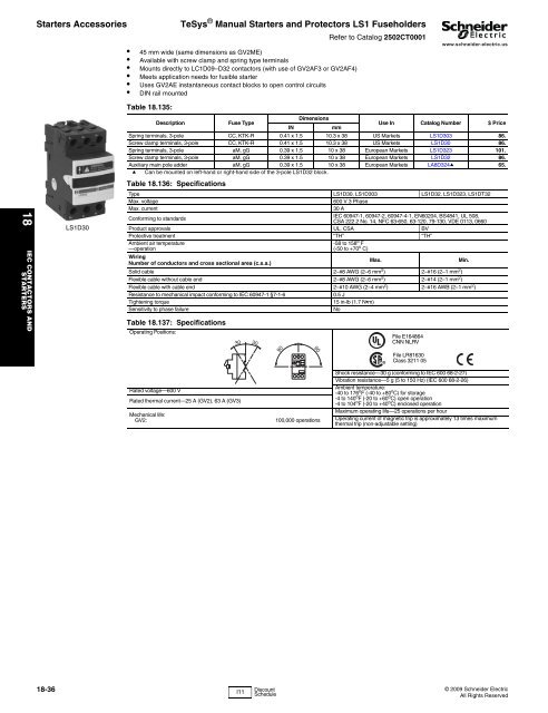
LS1D30<br />
TeSys ® Manual Starters and Protectors LS1 Fuseholders<br />
Refer to Catalog 2502CT0001<br />
• 45 mm wide (same dimensions as GV2ME)<br />
• Available with screw clamp and spring type terminals<br />
• Mounts directly to LC1D09–D32 contactors (with use of GV2AF3 or GV2AF4)<br />
• Meets application needs for fusible starter<br />
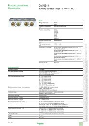
• Uses GV2AE instantaneous contact blocks to open control circuits<br />
• DIN rail mounted<br />
www.schneider-electric.us<br />
Table 18.135:<br />
Dimensions<br />
Description<br />
Fuse Type<br />
IN<br />
mm<br />
Use In Catalog Number $ Price<br />
Spring terminals, 3-pole CC, KTK-R 0.41 x 1.5 10.3 x 38 US Markets LS1D303 86.<br />
Screw clamp terminals, 3-pole CC, KTK-R 0.41 x 1.5 10.3 x 38 US Markets LS1D30 86.<br />
Spring terminals, 3-pole aM, gG 0.39 x 1.5 10 x 38 European Markets LS1D323 101.<br />
Screw clamp terminals, 3-pole aM, gG 0.39 x 1.5 10 x 38 European Markets LS1D32 86.<br />
Auxiliary main pole adder aM, gG 0.39 x 1.5 10 x 38 European Markets LA8D324a 65.<br />
a Can be mounted on left-hand or right-hand side of the 3-pole LS1D32 block.<br />
Table 18.136: Specifications<br />
Type LS1D30, LS1D303 LS1D32, LS1D323, LS1DT32<br />
Max. voltage<br />
600 V 3 Phase<br />
Max. current<br />
30 A<br />
Conforming to standards<br />
IEC 60947-1, 60947-2, 60947-4-1, EN60204, BS4841, UL 508,<br />
CSA 222.2 No. 14, NFC 63-650, 63-120, 79-130, VDE 0113, 0660<br />
Product approvals UL, CSA BV<br />
Protective treatment “TH” “TH”<br />
Ambient air temperature<br />
—operation<br />
-58 to 158 o F<br />
(-50 to +70 o C)<br />
Wiring<br />
Number of conductors and cross sectional area (c.s.a.)<br />
Max.<br />
Min.<br />
Solid cable 2–#8 AWG (2–6 mm 2 ) 2–#16 (2–1 mm 2 )<br />
Flexible cable without cable end 2–#8 AWG (2–6 mm 2 ) 2–#14 (2–1 mm 2 )<br />
Flexible cable with cable end 2–#10 AWG (2–4 mm 2 ) 2–#16 AWB (2–1 mm 2 )<br />
Resistance to mechanical impact conforming to IEC 60947-1 §7-1-6<br />
0.5 J<br />
Tightening torque<br />
15 in-lb (1.7 N•m)<br />
Sensitivity to phase failure<br />
No<br />
Table 18.137: Specifications<br />
Operating Positions:<br />
30<br />
30<br />
90<br />
90<br />
File E164864<br />
CNN NLRV<br />
File LR81630<br />
Class 3211 05<br />
Rated voltage—600 V<br />
Rated thermal current—25 A (GV2), 63 A (GV3)<br />
Mechanical life:<br />
GV2:<br />
100,000 operations<br />
Shock resistance—30 g (conforming to IEC 600 68-2-27)<br />
Vibration resistance—5 g (5 to 150 Hz) (IEC 600 68-2-26)<br />
Ambient temperature:<br />
-40 to 176 o F (-40 to +80 o C) for storage<br />
-4 to 140 o F (-20 to +60 o C) open operation<br />
-4 to 104 o F (-20 to +40 o C) enclosed operation<br />
Maximum operating life—25 operations per hour<br />
Operating current of magnetic trip is approximately 13 times maximum<br />
thermal trip (non-adjustable setting)<br />
18-36 © 2009 Schneider Electric<br />
I11 Discount<br />
Schedule<br />
All Rights Reserved