Lab 4.1 Configuring Frame Mode MPLS
Lab 4.1 Configuring Frame Mode MPLS
Lab 4.1 Configuring Frame Mode MPLS
- No tags were found...

Create successful ePaper yourself
Turn your PDF publications into a flip-book with our unique Google optimized e-Paper software.
<strong>Lab</strong> <strong>4.1</strong> <strong>Configuring</strong> <strong>Frame</strong> <strong>Mode</strong> <strong>MPLS</strong><br />
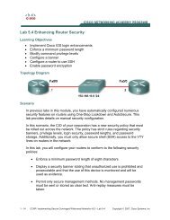
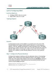
Learning Objectives<br />
• Configure EIGRP on a router<br />
• Configure <strong>Lab</strong>el Distribution Protocol on a router<br />
• Change the size of the Maximum Transmission Unit (MTU)<br />
• Verify <strong>MPLS</strong> behavior<br />
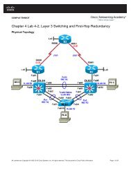
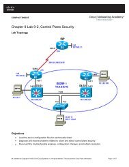
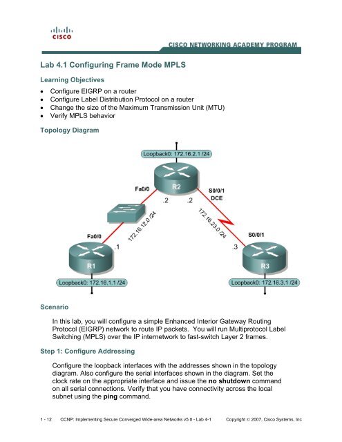
Topology Diagram<br />
Scenario<br />
In this lab, you will configure a simple Enhanced Interior Gateway Routing<br />
Protocol (EIGRP) network to route IP packets. You will run Multiprotocol <strong>Lab</strong>el<br />
Switching (<strong>MPLS</strong>) over the IP internetwork to fast-switch Layer 2 frames.<br />
Step 1: Configure Addressing<br />
Configure the loopback interfaces with the addresses shown in the topology<br />
diagram. Also configure the serial interfaces shown in the diagram. Set the<br />
clock rate on the appropriate interface and issue the no shutdown command<br />
on all serial connections. Verify that you have connectivity across the local<br />
subnet using the ping command.<br />
1 - 12 CCNP: Implementing Secure Converged Wide-area Networks v5.0 - <strong>Lab</strong> 4-1 Copyright © 2007, Cisco Systems, Inc
R1(config)# interface loopback 0<br />
R1(config-if)# ip address 172.16.1.1 255.255.255.0<br />
R1(config-if)# interface fastethernet 0/0<br />
R1(config-if)# ip address 172.16.12.1 255.255.255.0<br />
R1(config-if)# no shutdown<br />
R2(config)# interface loopback 0<br />
R2(config-if)# ip address 172.16.2.1 255.255.255.0<br />
R2(config-if)# interface fastethernet 0/0<br />
R2(config-if)# ip address 172.16.12.2 255.255.255.0<br />
R2(config-if)# no shutdown<br />
R2(config-if)# interface serial 0/0/1<br />
R2(config-if)# ip address 172.16.23.2 255.255.255.0<br />
R2(config-if)# clockrate 64000<br />
R2(config-if)# no shutdown<br />
R3(config)# interface loopback 0<br />
R3(config-if)# ip address 172.16.3.1 255.255.255.0<br />
R3(config-if)# interface serial 0/0/1<br />
R3(config-if)# ip address 172.16.23.3 255.255.255.0<br />
R3(config-if)# no shutdown<br />
Step 2: Configure EIGRP AS 1<br />
Configure EIGRP for AS1 on all three routers. Add the whole major network<br />
172.16.0.0 and disable automatic summarization.<br />
R1(config)# router eigrp 1<br />
R1(config-router)# no auto-summary<br />
R1(config-router)# network 172.16.0.0<br />
R2(config)# router eigrp 1<br />
R2(config-router)# no auto-summary<br />
R2(config-router)# network 172.16.0.0<br />
R3(config)# router eigrp 1<br />
R3(config-router)# no auto-summary<br />
R3(config-router)# network 172.16.0.0<br />
EIGRP neighbor adjacencies should form between R1 and R2 and between R2<br />
and R3. If the adjacencies do not form, troubleshoot by checking your interface<br />
configuration, EIGRP configuration, and physical connectivity.<br />
What impact does IP connectivity have on <strong>MPLS</strong><br />
Step 3: Observe CEF Operation<br />
Since all the routers have EIGRP adjacencies and are advertising the entire<br />
major 172.16.0.0 network, all routers should have full routing tables.<br />
2 - 12 CCNP: Implementing Secure Converged Wide-area Networks v5.0 - <strong>Lab</strong> 4-1 Copyright © 2007, Cisco Systems, Inc
R1# show ip route<br />
Codes: C - connected, S - static, R - RIP, M - mobile, B - BGP<br />
D - EIGRP, EX - EIGRP external, O - OSPF, IA - OSPF inter area<br />
N1 - OSPF NSSA external type 1, N2 - OSPF NSSA external type 2<br />
E1 - OSPF external type 1, E2 - OSPF external type 2<br />
i - IS-IS, su - IS-IS summary, L1 - IS-IS level-1, L2 - IS-IS level-2<br />
ia - IS-IS inter area, * - candidate default, U - per-user static route<br />
o - ODR, P - periodic downloaded static route<br />
Gateway of last resort is not set<br />
D<br />
C<br />
C<br />
D<br />
D<br />
172.16.0.0/24 is subnetted, 5 subnets<br />
172.16.23.0 [90/2172416] via 172.16.12.2, 00:01:56, FastEthernet0/0<br />
172.16.12.0 is directly connected, FastEthernet0/0<br />
172.16.1.0 is directly connected, Loopback0<br />
172.16.2.0 [90/156160] via 172.16.12.2, 00:01:56, FastEthernet0/0<br />
172.16.3.0 [90/2300416] via 172.16.12.2, 00:01:51, FastEthernet0/0<br />
On R1, if you perform a traceroute to the R3s loopback, you see the path the<br />
packet follows. This output changes slightly once we configure <strong>MPLS</strong>.<br />
R1# traceroute 172.16.3.1<br />
Type escape sequence to abort.<br />
Tracing the route to 172.16.3.1<br />
1 172.16.12.2 0 msec 0 msec 0 msec<br />
2 172.16.23.3 16 msec 12 msec *<br />
Cisco Express Forwarding (CEF) is Cisco’s proprietary Layer 3 switching<br />
algorithm for Cisco IOS routers. CEF allows forwarding to be distributed<br />
throughout the line cards on Cisco models like the Catalyst 6500. CEF also<br />
provides quicker switching than switching based on the routing table (process<br />
switching) or switching based on a standards-compliant forwarding information<br />
base (fast switching).<br />
What is the function of CEF<br />
Which information does CEF view as significant in making a forwarding<br />
determination for an IP packet<br />
You can also see that CEF is enabled by default by using the show ip cef<br />
command.<br />
3 - 12 CCNP: Implementing Secure Converged Wide-area Networks v5.0 - <strong>Lab</strong> 4-1 Copyright © 2007, Cisco Systems, Inc
R1# show ip cef<br />
Prefix Next Hop Interface<br />
0.0.0.0/0 drop Null0 (default route handler entry)<br />
0.0.0.0/32 receive<br />
172.16.1.0/24 attached Loopback0<br />
172.16.1.0/32 receive<br />
172.16.1.1/32 receive<br />
172.16.1.255/32 receive<br />
172.16.2.0/24 172.16.12.2 FastEthernet0/0<br />
172.16.3.0/24 172.16.12.2 FastEthernet0/0<br />
172.16.12.0/24 attached FastEthernet0/0<br />
172.16.12.0/32 receive<br />
172.16.12.1/32 receive<br />
172.16.12.2/32 172.16.12.2 FastEthernet0/0<br />
172.16.12.255/32 receive<br />
172.16.23.0/24 172.16.12.2 FastEthernet0/0<br />
224.0.0.0/4 drop<br />
224.0.0.0/24 receive<br />
255.255.255.255/32 receive<br />
Another important CEF command is the show ip cef non-recursive command<br />
which allows the user to display CEF forwarding information for prefixes<br />
installed in the routing table.<br />
R1# show ip cef non-recursive<br />
Prefix Next Hop Interface<br />
172.16.1.0/24 attached Loopback0<br />
172.16.2.0/24 172.16.12.2 FastEthernet0/0<br />
172.16.3.0/24 172.16.12.2 FastEthernet0/0<br />
172.16.12.0/24 attached FastEthernet0/0<br />
172.16.12.2/32 172.16.12.2 FastEthernet0/0<br />
172.16.23.0/24 172.16.12.2 FastEthernet0/0<br />
CEF records both the Layer 3 next-hop information and the Layer 2 frame nexthop<br />
information. CEF currently supports the following Layer 2 protocols: ATM,<br />
<strong>Frame</strong> Relay, Ethernet, Fiber Distributed Data Interface (FDDI), PPP, High-<br />
Level Datalink Control (HDLC), and tunnels.<br />
CEF is critical to the operation of <strong>MPLS</strong> on Cisco routers because <strong>MPLS</strong><br />
packets must be forwarded based on label. Since the CEF architecture can<br />
support multiple protocols such as IPv4, IPv6, CEF switching could naturally be<br />
extended to support <strong>MPLS</strong> labels as well.<br />
CEF should be enabled by default. If CEF is not enabled, issue the ip cef<br />
command in global configuration mode on each router.<br />
Step 4: Enable <strong>MPLS</strong> on All Physical Interfaces<br />
<strong>MPLS</strong> is a standardized protocol that allows routers to switch packets based on<br />
labels, rather than route switch packets based on standards in the protocol’s<br />
routing formula. Under normal IP routing, every intermediate system looks up<br />
the destination prefix of an IP packet in the Routing Information Base (RIB) of a<br />
router or in the Forwarding Information Base (FIB) of a fast switch at every<br />
Layer 3 node. Instead of switching that is based on prefix, the first router<br />
running <strong>MPLS</strong> can encapsulate the IP packet in an <strong>MPLS</strong> frame and then<br />
4 - 12 CCNP: Implementing Secure Converged Wide-area Networks v5.0 - <strong>Lab</strong> 4-1 Copyright © 2007, Cisco Systems, Inc
further encapsulate the packet in the Layer 2 frame before sending it across<br />
one of many supported Layer 2 media. At the next <strong>MPLS</strong>-enabled <strong>Lab</strong>el Switch<br />
Router (LSR), the <strong>MPLS</strong> frame is read and the IP packet is switched as an<br />
<strong>MPLS</strong> frame from router to router with little rewrite at each node.<br />
This allows routers to switch multiple protocols (hence the name) using the<br />
same switching mechanism, as well as perform some other functionality not<br />
available in traditional destination-based forwarding, including Layer 2 VPNs<br />
(AToM), Layer 3 VPNs, and traffic engineering. <strong>MPLS</strong> runs between Layers 2<br />
and 3 of the OSI model and, because of this, is sometimes said to run at Layer<br />
2½. The <strong>MPLS</strong> header is 4 bytes long and includes a 20-bit label.<br />
<strong>Configuring</strong> the interface-level command mpls ip on an interface tells the router<br />
to switch <strong>MPLS</strong> packets inbound and outbound on that interface as well as<br />
attempt to bring up <strong>MPLS</strong> adjacencies with the <strong>Lab</strong>el Distribution Protocol<br />
(LDP) out that egress interface. LDP facilitates communication between <strong>MPLS</strong><br />
peers by allowing them to inform each other of labels to assign packets to<br />
particular destinations based on Layer 2, Layer 3, or other significant<br />
information.<br />
Configure <strong>MPLS</strong> on all physical interfaces in the topology.<br />
NOTE: If you are running the 12.4 version of the IOS on your routers, then the<br />
mpls ip command is what you will use in this lab. However, when Cisco first<br />
developed packet-labeling technology, it was called tag switching. Therefore, if<br />
you are running an older version of the IOS, then you may see one of two<br />
different variations. The first variation is that your router will accept the mpls ip<br />
command. However, the commands will be stored in IOS as tag-switching<br />
commands. The second variation is that your router will not accept the mpls ip<br />
command. In this event, the mpls ip command may be entered as the tagswitching<br />
ip command. Try the newer commands first, beginning with the<br />
mpls keyword.<br />
R1(config)# interface fastethernet0/0<br />
R1(config-if)# mpls ip<br />
R2(config)# interface fastethernet0/0<br />
R2(config-if)# mpls ip<br />
*Jan 31 08:28:54.315: %LDP-5-NBRCHG: LDP Neighbor 172.16.1.1:0 (1) is UP<br />
R2(config-if)# interface serial0/0/1<br />
R2(config-if)# mpls ip<br />
R3(config)# interface serial0/0/1<br />
R3(config-if)# mpls ip<br />
*Jan 31 08:32:11.571: %LDP-5-NBRCHG: LDP Neighbor 172.16.2.1:0 (1) is UP<br />
Notice that as you configure <strong>MPLS</strong> on both ends of a connection, IOS logs a<br />
messages to the console on both routers indicating that an LDP neighbor<br />
adjacency has formed.<br />
5 - 12 CCNP: Implementing Secure Converged Wide-area Networks v5.0 - <strong>Lab</strong> 4-1 Copyright © 2007, Cisco Systems, Inc
Although you are going to use LDP in this lab, there is another Ciscoproprietary<br />
label exchanging protocol called Tag Distribution Protocol (TDP)<br />
which was part of the Cisco Tag Switching architecture. To change the protocol<br />
being used, use the mpls label protocol protocol command either on a global<br />
level at the global configuration prompt or on a per-interface basis, using the<br />
interface-level version of this command. Cisco TDP and <strong>MPLS</strong> LDP are nearly<br />
identical in function, but use incompatible message formats and some different<br />
procedures. Cisco is changing from TDP to a fully compliant LDP.<br />
Step 5: Verify <strong>MPLS</strong> Configuration<br />
<strong>MPLS</strong> has many show commands that you can use to verify proper <strong>MPLS</strong><br />
operation. Issue the show mpls interfaces command to see a quick summary<br />
of interfaces configured with <strong>MPLS</strong>. Keep in mind that you will see this output<br />
because you applied the mpls ip command to these interfaces.<br />
R1# show mpls interfaces<br />
Interface IP Tunnel Operational<br />
FastEthernet0/0 Yes (ldp) No Yes<br />
R2# show mpls interfaces<br />
Interface IP Tunnel Operational<br />
FastEthernet0/0 Yes (ldp) No Yes<br />
Serial0/0/1 Yes (ldp) No Yes<br />
R3# show mpls interfaces<br />
Interface IP Tunnel Operational<br />
Serial0/0/1 Yes (ldp) No Yes<br />
Issue the show mpls ldp discovery command to find out local sources for LDP<br />
exchanges and the show mpls ldp neighbor command to show LDP<br />
adjacencies. Notice that <strong>MPLS</strong> chooses its IDs based on loopback interfaces,<br />
similar to other protocols such asOpen Shortest Path First (OSPF), Border<br />
Gateway Protocol (BGP).<br />
R1# show mpls ldp discovery<br />
Local LDP Identifier:<br />
172.16.1.1:0<br />
Discovery Sources:<br />
Interfaces:<br />
FastEthernet0/0 (ldp): xmit/recv<br />
LDP Id: 172.16.2.1:0; no host route<br />
R1# show mpls ldp neighbor<br />
Peer LDP Ident: 172.16.2.1:0; Local LDP Ident 172.16.1.1:0<br />
TCP connection: 172.16.2.1.49525 - 172.16.1.1.646<br />
State: Oper; Msgs sent/rcvd: 29/26; Downstream<br />
Up time: 00:16:40<br />
LDP discovery sources:<br />
FastEthernet0/0, Src IP addr: 172.16.12.2<br />
Addresses bound to peer LDP Ident:<br />
172.16.12.2 172.16.23.2 172.16.2.1<br />
R2# show mpls ldp discovery<br />
6 - 12 CCNP: Implementing Secure Converged Wide-area Networks v5.0 - <strong>Lab</strong> 4-1 Copyright © 2007, Cisco Systems, Inc
Local LDP Identifier:<br />
172.16.2.1:0<br />
Discovery Sources:<br />
Interfaces:<br />
FastEthernet0/0 (ldp): xmit/recv<br />
LDP Id: 172.16.1.1:0; no host route<br />
Serial0/0/1 (ldp): xmit/recv<br />
LDP Id: 172.16.3.1:0; no host route<br />
R2# show mpls ldp neighbor<br />
Peer LDP Ident: 172.16.1.1:0; Local LDP Ident 172.16.2.1:0<br />
TCP connection: 172.16.1.1.646 - 172.16.2.1.49525<br />
State: Oper; Msgs sent/rcvd: 27/30; Downstream<br />
Up time: 00:17:06<br />
LDP discovery sources:<br />
FastEthernet0/0, Src IP addr: 172.16.12.1<br />
Addresses bound to peer LDP Ident:<br />
172.16.12.1 172.16.1.1<br />
Peer LDP Ident: 172.16.3.1:0; Local LDP Ident 172.16.2.1:0<br />
TCP connection: 172.16.3.1.34352 - 172.16.2.1.646<br />
State: Oper; Msgs sent/rcvd: 27/26; Downstream<br />
Up time: 00:16:23<br />
LDP discovery sources:<br />
Serial0/0/1, Src IP addr: 172.16.23.3<br />
Addresses bound to peer LDP Ident:<br />
172.16.23.3 172.16.3.1<br />
R3# show mpls ldp discovery<br />
Local LDP Identifier:<br />
172.16.3.1:0<br />
Discovery Sources:<br />
Interfaces:<br />
Serial0/0/1 (ldp): xmit/recv<br />
LDP Id: 172.16.2.1:0; no host route<br />
R3# show mpls ldp neighbor<br />
Peer LDP Ident: 172.16.2.1:0; Local LDP Ident 172.16.3.1:0<br />
TCP connection: 172.16.2.1.646 - 172.16.3.1.34352<br />
State: Oper; Msgs sent/rcvd: 27/28; Downstream<br />
Up time: 00:17:19<br />
LDP discovery sources:<br />
Serial0/0/1, Src IP addr: 172.16.23.2<br />
Addresses bound to peer LDP Ident:<br />
172.16.12.2 172.16.23.2 172.16.2.1<br />
What interface does LDP use on R1 to identify itself to other LDP peers<br />
What transport protocol does LDP use to communicate with other LDP peers<br />
7 - 12 CCNP: Implementing Secure Converged Wide-area Networks v5.0 - <strong>Lab</strong> 4-1 Copyright © 2007, Cisco Systems, Inc
In the configuration you set up in Step 4, all routers are acting as <strong>Lab</strong>el Switch<br />
Routers (LSRs) and running LDP. On LSRs, each forwarding equivalence class<br />
(in this case, each routable IP prefix) is assigned an <strong>MPLS</strong> label. LDP<br />
automatically distributes labels to peers to be used when sending traffic to<br />
specific destinations through the LSR. Once labels have been distributed,<br />
switching for <strong>MPLS</strong> packets is done through the <strong>Lab</strong>el Information Base (LIB).<br />
Display the contents of the LIB using the show mpls ldp bindings command.<br />
There is a binding for every routed prefix; however, the bindings may vary from<br />
router to router since they can get swapped at each hop. In a larger network,<br />
the way labels are swapped is easier to see. The LIB is also referred to on<br />
Cisco routers as the TIB, a legacy name from Tag Switching. Do not be<br />
alarmed to see the LIB entries listed instead as TIB entries: this does not signal<br />
that TDP is the protocol being used for distribution.<br />
R1# show mpls ldp bindings<br />
tib entry: 172.16.1.0/24, rev 6<br />
local binding: tag: imp-null<br />
remote binding: tsr: 172.16.2.1:0, tag: 16<br />
tib entry: 172.16.2.0/24, rev 8<br />
local binding: tag: 17<br />
remote binding: tsr: 172.16.2.1:0, tag: imp-null<br />
tib entry: 172.16.3.0/24, rev 10<br />
local binding: tag: 18<br />
remote binding: tsr: 172.16.2.1:0, tag: 17<br />
tib entry: 172.16.12.0/24, rev 4<br />
local binding: tag: imp-null<br />
remote binding: tsr: 172.16.2.1:0, tag: imp-null<br />
tib entry: 172.16.23.0/24, rev 2<br />
local binding: tag: 16<br />
remote binding: tsr: 172.16.2.1:0, tag: imp-null<br />
R2# show mpls ldp bindings<br />
tib entry: 172.16.1.0/24, rev 6<br />
local binding: tag: 16<br />
remote binding: tsr: 172.16.1.1:0, tag: imp-null<br />
remote binding: tsr: 172.16.3.1:0, tag: 17<br />
tib entry: 172.16.2.0/24, rev 8<br />
local binding: tag: imp-null<br />
remote binding: tsr: 172.16.1.1:0, tag: 17<br />
remote binding: tsr: 172.16.3.1:0, tag: 18<br />
tib entry: 172.16.3.0/24, rev 10<br />
local binding: tag: 17<br />
remote binding: tsr: 172.16.1.1:0, tag: 18<br />
remote binding: tsr: 172.16.3.1:0, tag: imp-null<br />
tib entry: 172.16.12.0/24, rev 4<br />
local binding: tag: imp-null<br />
remote binding: tsr: 172.16.1.1:0, tag: imp-null<br />
remote binding: tsr: 172.16.3.1:0, tag: 16<br />
tib entry: 172.16.23.0/24, rev 2<br />
local binding: tag: imp-null<br />
remote binding: tsr: 172.16.1.1:0, tag: 16<br />
remote binding: tsr: 172.16.3.1:0, tag: imp-null<br />
R3# show mpls ldp bindings<br />
tib entry: 172.16.1.0/24, rev 6<br />
local binding: tag: 17<br />
remote binding: tsr: 172.16.2.1:0, tag: 16<br />
8 - 12 CCNP: Implementing Secure Converged Wide-area Networks v5.0 - <strong>Lab</strong> 4-1 Copyright © 2007, Cisco Systems, Inc
tib entry: 172.16.2.0/24, rev 8<br />
local binding: tag: 18<br />
remote binding: tsr: 172.16.2.1:0, tag: imp-null<br />
tib entry: 172.16.3.0/24, rev 10<br />
local binding: tag: imp-null<br />
remote binding: tsr: 172.16.2.1:0, tag: 17<br />
tib entry: 172.16.12.0/24, rev 4<br />
local binding: tag: 16<br />
remote binding: tsr: 172.16.2.1:0, tag: imp-null<br />
tib entry: 172.16.23.0/24, rev 2<br />
local binding: tag: imp-null<br />
remote binding: tsr: 172.16.2.1:0, tag: imp-null<br />
The local bindings are generated by LDP on a <strong>Lab</strong>el Switch Router when LDP<br />
is enabled. A label is generated for every prefix in the routing table. These<br />
labels are then sent to all of the router’s LDP peers. A tag of implicit-NULL<br />
(“imp-null” in the output of the command show mpls ldp bindings ) is<br />
advertised when the packet with not be forwarded locally based on label, but<br />
based on prefix. This situation regularly occurs with connected networks.<br />
For instance, assume R2 and R3 have already peered with each other using<br />
LDP. Now R1 begins running <strong>MPLS</strong> and attempts to peer to R2:<br />
1. R1 generates the locally bound label, namely 18, for the prefix<br />
172.16.3.0/24 in its routing table.<br />
2. R1 advertises the local binding to its LDP peer, R2.<br />
3. R2 enters R1’s binding for the 172.16.3.0/24 prefix, now classified as a<br />
remote binding, into its LIB, regardless of whether it uses it to reach the<br />
destination network. The remote binding for this IP prefix through R1 is<br />
label 18.<br />
4. Based on the routing table, R2 will use R3 as the next hop for the<br />
172.16.3.0/24. R2 will not forward IP packets inside an <strong>MPLS</strong><br />
encapsulation, but rather simply as IP packets because R3 has<br />
advertised the label of implicit-NULL to R2.<br />
What is the significance of the “local binding” entry<br />
What is the significance of a “remote binding” entry<br />
9 - 12 CCNP: Implementing Secure Converged Wide-area Networks v5.0 - <strong>Lab</strong> 4-1 Copyright © 2007, Cisco Systems, Inc
On R2, why is there more than one remote binding for each of the networks in<br />
the diagram<br />
Note that LDP assigns local labels to all Interior Gateway Protocol (IGP)<br />
prefixes and advertises the bindings to all LDP peers. The concept of split<br />
horizon does not exist; an LDP peer assigns its own local label to a prefix and<br />
advertises that back to the other LDP peer, even though that other LDP peer<br />
owns the prefix (it is a connected prefix) or that other LDP peer is the<br />
downstream LSR.<br />
What is the meaning of the implicit NULL label<br />
As mentioned earlier, traceroute would differ slightly once <strong>MPLS</strong> was set up.<br />
The output now includes labels for each hop. Unfortunately, because of the size<br />
of this network, you only see one label. In a larger network, you would see more<br />
hops, and therefore more labels.<br />
R1# traceroute 172.16.3.1<br />
Type escape sequence to abort.<br />
Tracing the route to 172.16.3.1<br />
1 172.16.12.2 [<strong>MPLS</strong>: <strong>Lab</strong>el 17 Exp 0] 44 msec 44 msec 48 msec<br />
2 172.16.23.3 12 msec 12 msec *<br />
Step 6: Change <strong>MPLS</strong> MTU<br />
Because you are adding in extra header information to packets, the MTU of<br />
packets can change. Remember that each <strong>MPLS</strong> header is 4 bytes. The default<br />
MTU size of <strong>MPLS</strong> packets is taken from the interface it is running on, which in<br />
the case of Ethernet is 1500 bytes. To verify this, use the show mpls<br />
interfaces interface-type interface-number detail command to the Ethernet<br />
connections of R1 and R2.<br />
R1# show mpls interfaces fastethernet 0/0 detail<br />
Interface FastEthernet0/0:<br />
IP labeling enabled (ldp):<br />
Interface config<br />
LSP Tunnel labeling not enabled<br />
BGP tagging not enabled<br />
10 - 12 CCNP: Implementing Secure Converged Wide-area Networks v5.0 - <strong>Lab</strong> 4-1 Copyright © 2007, Cisco Systems, Inc
Tagging operational<br />
Fast Switching Vectors:<br />
IP to <strong>MPLS</strong> Fast Switching Vector<br />
<strong>MPLS</strong> Turbo Vector<br />
MTU = 1500<br />
R2# show mpls interfaces fastethernet 0/0 detail<br />
Interface FastEthernet0/0:<br />
IP labeling enabled (ldp):<br />
Interface config<br />
LSP Tunnel labeling not enabled<br />
BGP tagging not enabled<br />
Tagging operational<br />
Fast Switching Vectors:<br />
IP to <strong>MPLS</strong> Fast Switching Vector<br />
<strong>MPLS</strong> Turbo Vector<br />
MTU = 1500<br />
For this lab, we will change the Ethernet connection between R1 and R2 to<br />
support 2 <strong>MPLS</strong> headers, so we will change the <strong>MPLS</strong> MTU to 1508 on their<br />
Fast Ethernet interfaces. To change the <strong>MPLS</strong> MTU, use the mpls mtu size<br />
command in interface configuration mode. Verify the change using the show<br />
mpls interfaces interface detail command used earlier.<br />
R1(config)# interface fastethernet 0/0<br />
R1(config-if)# mpls mtu 1508<br />
R2(config)# interface fastethernet0/0<br />
R2(config-if)# mpls mtu 1508<br />
R1# show mpls interface fastethernet 0/0 detail<br />
Interface FastEthernet0/0:<br />
IP labeling enabled (ldp):<br />
Interface config<br />
LSP Tunnel labeling not enabled<br />
BGP tagging not enabled<br />
Tagging operational<br />
Fast Switching Vectors:<br />
IP to <strong>MPLS</strong> Fast Switching Vector<br />
<strong>MPLS</strong> Turbo Vector<br />
MTU = 1508<br />
R2# show mpls interface fastethernet 0/0 detail<br />
Interface FastEthernet0/0:<br />
IP labeling enabled (ldp):<br />
Interface config<br />
LSP Tunnel labeling not enabled<br />
BGP tagging not enabled<br />
Tagging operational<br />
Fast Switching Vectors:<br />
IP to <strong>MPLS</strong> Fast Switching Vector<br />
<strong>MPLS</strong> Turbo Vector<br />
MTU = 1508<br />
Final Configurations<br />
R1# show run<br />
!<br />
hostname R1<br />
!<br />
11 - 12 CCNP: Implementing Secure Converged Wide-area Networks v5.0 - <strong>Lab</strong> 4-1 Copyright © 2007, Cisco Systems, Inc
interface Loopback0<br />
ip address 172.16.1.1 255.255.255.0<br />
!<br />
interface FastEthernet0/0<br />
ip address 172.16.12.1 255.255.255.0<br />
mpls ip<br />
mpls mtu 1508<br />
no shutdown<br />
!<br />
router eigrp 1<br />
network 172.16.0.0<br />
no auto-summary<br />
!<br />
end<br />
R2# show run<br />
!<br />
hostname R2<br />
!<br />
interface Loopback0<br />
ip address 172.16.2.1 255.255.255.0<br />
!<br />
interface FastEthernet0/0<br />
ip address 172.16.12.2 255.255.255.0<br />
mpls ip<br />
mpls mtu 1508<br />
no shutdown<br />
!<br />
interface Serial0/0/1<br />
ip address 172.16.23.2 255.255.255.0<br />
mpls ip<br />
clock rate 64000<br />
no shutdown<br />
!<br />
router eigrp 1<br />
network 172.16.0.0<br />
no auto-summary<br />
!<br />
end<br />
R3# show run<br />
!<br />
hostname R3<br />
!<br />
interface Loopback0<br />
ip address 172.16.3.1 255.255.255.0<br />
!<br />
interface Serial0/0/1<br />
ip address 172.16.23.3 255.255.255.0<br />
mpls ip<br />
no shutdown<br />
!<br />
router eigrp 1<br />
network 172.16.0.0<br />
no auto-summary<br />
!<br />
end<br />
12 - 12 CCNP: Implementing Secure Converged Wide-area Networks v5.0 - <strong>Lab</strong> 4-1 Copyright © 2007, Cisco Systems, Inc