Lab 4.1 Configuring Frame Mode MPLS
Lab 4.1 Configuring Frame Mode MPLS
Lab 4.1 Configuring Frame Mode MPLS
- No tags were found...

You also want an ePaper? Increase the reach of your titles
YUMPU automatically turns print PDFs into web optimized ePapers that Google loves.
further encapsulate the packet in the Layer 2 frame before sending it across<br />
one of many supported Layer 2 media. At the next <strong>MPLS</strong>-enabled <strong>Lab</strong>el Switch<br />
Router (LSR), the <strong>MPLS</strong> frame is read and the IP packet is switched as an<br />
<strong>MPLS</strong> frame from router to router with little rewrite at each node.<br />
This allows routers to switch multiple protocols (hence the name) using the<br />
same switching mechanism, as well as perform some other functionality not<br />
available in traditional destination-based forwarding, including Layer 2 VPNs<br />
(AToM), Layer 3 VPNs, and traffic engineering. <strong>MPLS</strong> runs between Layers 2<br />
and 3 of the OSI model and, because of this, is sometimes said to run at Layer<br />
2½. The <strong>MPLS</strong> header is 4 bytes long and includes a 20-bit label.<br />
<strong>Configuring</strong> the interface-level command mpls ip on an interface tells the router<br />
to switch <strong>MPLS</strong> packets inbound and outbound on that interface as well as<br />
attempt to bring up <strong>MPLS</strong> adjacencies with the <strong>Lab</strong>el Distribution Protocol<br />
(LDP) out that egress interface. LDP facilitates communication between <strong>MPLS</strong><br />
peers by allowing them to inform each other of labels to assign packets to<br />
particular destinations based on Layer 2, Layer 3, or other significant<br />
information.<br />
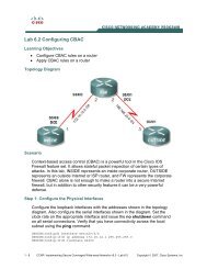
Configure <strong>MPLS</strong> on all physical interfaces in the topology.<br />
NOTE: If you are running the 12.4 version of the IOS on your routers, then the<br />
mpls ip command is what you will use in this lab. However, when Cisco first<br />
developed packet-labeling technology, it was called tag switching. Therefore, if<br />
you are running an older version of the IOS, then you may see one of two<br />
different variations. The first variation is that your router will accept the mpls ip<br />
command. However, the commands will be stored in IOS as tag-switching<br />
commands. The second variation is that your router will not accept the mpls ip<br />
command. In this event, the mpls ip command may be entered as the tagswitching<br />
ip command. Try the newer commands first, beginning with the<br />
mpls keyword.<br />
R1(config)# interface fastethernet0/0<br />
R1(config-if)# mpls ip<br />
R2(config)# interface fastethernet0/0<br />
R2(config-if)# mpls ip<br />
*Jan 31 08:28:54.315: %LDP-5-NBRCHG: LDP Neighbor 172.16.1.1:0 (1) is UP<br />
R2(config-if)# interface serial0/0/1<br />
R2(config-if)# mpls ip<br />
R3(config)# interface serial0/0/1<br />
R3(config-if)# mpls ip<br />
*Jan 31 08:32:11.571: %LDP-5-NBRCHG: LDP Neighbor 172.16.2.1:0 (1) is UP<br />
Notice that as you configure <strong>MPLS</strong> on both ends of a connection, IOS logs a<br />
messages to the console on both routers indicating that an LDP neighbor<br />
adjacency has formed.<br />
5 - 12 CCNP: Implementing Secure Converged Wide-area Networks v5.0 - <strong>Lab</strong> 4-1 Copyright © 2007, Cisco Systems, Inc