Design and Performance Evaluation of an Ice Block Making Machine
Design and Performance Evaluation of an Ice Block Making Machine
Design and Performance Evaluation of an Ice Block Making Machine

You also want an ePaper? Increase the reach of your titles
YUMPU automatically turns print PDFs into web optimized ePapers that Google loves.
VOL. 3, NO. 4, April 2013 ISSN 2225-7217<br />
ARPN Journal <strong>of</strong> Science <strong><strong>an</strong>d</strong> Technology<br />
©2011-2013. All rights reserved.<br />
http://www.ejournal<strong>of</strong>science.org<br />
<strong>Design</strong> <strong><strong>an</strong>d</strong> <strong>Perform<strong>an</strong>ce</strong> <strong>Evaluation</strong> <strong>of</strong> <strong>an</strong> <strong>Ice</strong> <strong>Block</strong> <strong>Making</strong> <strong>Machine</strong><br />
1 A. Nasir, 2 A. Mohammed, 3 A. S. Adegoke, 4 H. T. Abdulkarim<br />
1,2,3, Department <strong>of</strong> Mech<strong>an</strong>ical Engineering, Federal University <strong>of</strong> Technology, Minna, Nigeria<br />
4 Department <strong>of</strong> Electrical/Electronic Technology, College <strong>of</strong> Education, Minna, Nigeria<br />
ABSTRACT<br />
The ambient temperature <strong>of</strong> tropical countries like Nigeria is as high as 40 o C during the dry season. This ultimately gives<br />
rise to increase in dem<strong><strong>an</strong>d</strong> for ice which is used to reduce the temperature <strong>of</strong> water, s<strong>of</strong>t-drinks as well as other uses. This<br />
increase in dem<strong><strong>an</strong>d</strong> for ice block makes the design <strong><strong>an</strong>d</strong> construction <strong>of</strong> a machine which c<strong>an</strong> be used for the production <strong>of</strong><br />
ice within a short period <strong>of</strong> time in order to save energy <strong><strong>an</strong>d</strong> time imperative <strong><strong>an</strong>d</strong> a worthwhile venture. This paper presents<br />
the design <strong><strong>an</strong>d</strong> perform<strong>an</strong>ce evaluation <strong>of</strong> a model ice block making machine that c<strong>an</strong> freeze water quickly. In order to<br />
achieve quick freezing, certain design consideration, such as the qu<strong>an</strong>tity <strong>of</strong> water to be frozen, the choice <strong>of</strong> cooling<br />
system <strong><strong>an</strong>d</strong> the methodology <strong>of</strong> attaining the desired result. The methodology adopted involves increasing the area <strong>of</strong> heat<br />
tr<strong>an</strong>sfer <strong><strong>an</strong>d</strong> employing a vapour compression refrigerating system to generate the refrigerating effect. The design <strong>an</strong>alysis<br />
<strong>of</strong> the evaporator, compressor <strong><strong>an</strong>d</strong> condenser are presented in details. This paper also reports on the material selection,<br />
fabrication methods <strong><strong>an</strong>d</strong> the experimental procedures <strong><strong>an</strong>d</strong> results. A temperature <strong>of</strong> -14 0 C was achieved in the freezing<br />
chamber <strong><strong>an</strong>d</strong> a freezing duration <strong>of</strong> 70 minutes for 1kg <strong>of</strong> ice block as test results.<br />
Keywords: <strong>Design</strong>, Refrigeration, Quick Freezing, <strong>Ice</strong>-<strong>Block</strong>.<br />
1. INTRODUCTION<br />
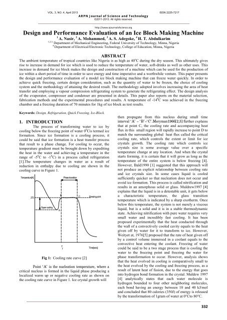
The process <strong>of</strong> tr<strong>an</strong>sforming water to ice by<br />
cooling below the freezing point <strong>of</strong> water 0 0 Cis termed ice<br />
formation. Since ice formation is a cooling process, it<br />
could be said that ice formation is a heat tr<strong>an</strong>sfer process<br />
that result to a phase ch<strong>an</strong>ge. For cooling to occur, the<br />
temperature gradient must be brought down by expediting<br />
the heat in the water <strong><strong>an</strong>d</strong> achieving a temperature in the<br />
r<strong>an</strong>ge <strong>of</strong> -5 0 C to -1 0 C) in a process called refrigeration<br />
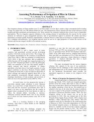
[1].The temperature ch<strong>an</strong>ges in water as a result <strong>of</strong><br />
reduction in enthalpy due to cooling are shown in the<br />
cooling curve in Figure 1.<br />
Temperature[K]<br />
273<br />
Super cooling<br />
A<br />
B<br />
T<br />
f<br />
Phase tr<strong>an</strong>sition<br />
Fig 1: Cooling rate curve [2]<br />
C<br />
Freezing point<br />
Time[secs]<br />
Point ‘A’ is the nucleation temperature, where a<br />
critical nucleus is formed in the liquid phase producing a<br />
localized warm up or negative cooling rate as shown on<br />
the cooling rate curve in Figure 1. <strong>Ice</strong> crystal growth will<br />
then propagate from this nucleus during small time<br />
interval ‘A’ – ‘B’–‘C’.Merym<strong>an</strong>1966[2,3] further explains<br />
that at point C, the cooling rate <strong><strong>an</strong>d</strong> accomp<strong>an</strong>ying heat<br />
flux in this small region will rapidly increase to point D to<br />
match the surrounding global heat flux called the critical<br />
cooling rate, which controls the extent or limit for ice<br />
crystals growth. The cooling rate which controls ice<br />
crystals size is some average value over a specific<br />
temperature ch<strong>an</strong>ge at <strong>an</strong>y location. And when the crystal<br />
starts forming, it is certain that it will grow as long as the<br />
temperature <strong>of</strong> the entire system is below freezing [4].<br />
However, Bald1990 [1] suggested that this approach will<br />
not produce <strong>an</strong> explicit relationship between cooling rate<br />
<strong><strong>an</strong>d</strong> ice crystals size. In some cases liquid is cooled<br />
sufficiently quicker so that nucleation does not occur <strong><strong>an</strong>d</strong><br />
avoid ice formation. This process is called nitrification <strong><strong>an</strong>d</strong><br />
results in <strong>an</strong> amorphous solid or glass. Muldrew1997 [4]<br />
explains that the liquid is in a detestable unit, it gets below<br />
a characteristic temperature, the glass tr<strong>an</strong>sition<br />
temperature which is indicated by a sharp exotherm. Once<br />
below this temperature, the system is not merely a viscous<br />
liquid, but is a solid <strong><strong>an</strong>d</strong> it is in a stable thermodynamic<br />
state. Achieving nitrification with pure water requires very<br />
small water <strong><strong>an</strong>d</strong> incredibly fast cooling. It has been<br />
proposed experimentally that the heat conducted through<br />
the wall <strong>of</strong> a convectively cooled cavity equals to the heat<br />
given <strong>of</strong>f by water for it to tr<strong>an</strong>sform to ice. However,<br />
Weityet at, 1976[5] proposed that the rate <strong>of</strong> heat given <strong>of</strong>f<br />
by a control volume immersed in a cool<strong>an</strong>t equals to the<br />
convective heat entering the cool<strong>an</strong>t. Freezing <strong>of</strong> water<br />
could be said to be a two stage process that is cooling the<br />
water to the freezing point <strong><strong>an</strong>d</strong> freezing the water for<br />
phase tr<strong>an</strong>sformation to occur. However, <strong>an</strong>alysis shows<br />
that the heat evolved in cooling is comparatively small to<br />
the heat evolved by the cooling <strong><strong>an</strong>d</strong> freezing process, as a<br />
result <strong>of</strong> latent heat <strong>of</strong> fusion, due to the energy that goes<br />
into hydrogen bond formation in the crystal. Muldew 1997<br />
[4] <strong>an</strong>alytically states that each water molecule is<br />
hydrogen bounded to four other neighboring molecules,<br />
each bond having <strong>an</strong> energy between 10 <strong><strong>an</strong>d</strong> 40 kJ/mol<br />
<strong><strong>an</strong>d</strong> concluded that 80 calories (350J) <strong>of</strong> energy is released<br />
by the tr<strong>an</strong>sformation <strong>of</strong> 1gram <strong>of</strong> water at 0°Cto 80°C.<br />
332
VOL. 3, NO. 4, April 2013 ISSN 2225-7217<br />
ARPN Journal <strong>of</strong> Science <strong><strong>an</strong>d</strong> Technology<br />
©2011-2013. All rights reserved.<br />
The applications <strong>of</strong> refrigeration include<br />
household (domestic) refrigerators, industrial freezers,<br />
cryogenics, air conditioning <strong><strong>an</strong>d</strong> heat pumps [3]. In<br />
developing tropical countries like Nigeria, the use <strong>of</strong><br />
refrigeration as a domestic refrigerators are the most<br />
prevalent due to very high temperatures. Domestic<br />
refrigerators are used for chilling beverages at homes,<br />
<strong>of</strong>fices, seminars, cocktail parties, general meetings,<br />
c<strong>an</strong>teens <strong><strong>an</strong>d</strong> conferences. Oladunjoye [6] designed <strong><strong>an</strong>d</strong><br />
constructed a two compartment freezing unit to enh<strong>an</strong>ce<br />
the availability <strong>of</strong> ice block. The need to have cold<br />
beverages during such meetings necessitated the design <strong>of</strong><br />
<strong>an</strong> innovative refrigerated cooling table to be used for<br />
conference services [7, 8]. The dem<strong><strong>an</strong>d</strong> for ice block has<br />
increased due to high temperature experienced in these<br />
tropical countries. <strong>Ice</strong> block making machine c<strong>an</strong> be<br />
accomplished by variety <strong>of</strong> refrigerating effect generating<br />
methods. The time <strong>of</strong> freezing <strong>of</strong> the water is <strong>of</strong><br />
considerable import<strong>an</strong>ce when designing <strong>an</strong> ice block<br />
making machine. The coefficient <strong>of</strong> perform<strong>an</strong>ce (COP)<br />
<strong><strong>an</strong>d</strong> the energy used per system is also a vital factor in ice<br />
block machine design. In order to increase the heat<br />
tr<strong>an</strong>sfer area, the coil was wound round the evaporator.<br />
Several designs were made at different time by different<br />
designers using adsorption system but they usually have a<br />
drawback <strong>of</strong> low C.O.P (0.12 to 0.23) [9]. This paper<br />
presents the design <strong><strong>an</strong>d</strong> evaluation <strong>of</strong> <strong>an</strong> ice-block making<br />
machine using the principle <strong>of</strong> a vapour compression<br />
system.<br />
2. VAPOUR COMPRESSION SYSTEM<br />
The ice-making machine was designed on the<br />
basis <strong>of</strong> vapour compression refrigeration cycle which is<br />
simply a refrigeration cycle that absorbs heat from a cool<br />
environment <strong><strong>an</strong>d</strong> rejects it to a warm environment by the<br />
vacuum vaporization <strong>of</strong> a volatile liquid. Vapour<br />
compression refrigeration cycles specifically have two<br />
adv<strong>an</strong>tages which made it best suitable for the design <strong>of</strong><br />
the ice making machine. First, it exploits the large thermal<br />
energy required to ch<strong>an</strong>ge a liquid to a vapour thus this<br />
will enh<strong>an</strong>ce the removal <strong>of</strong> high qu<strong>an</strong>tity <strong>of</strong> heat from<br />
water to cause a phase ch<strong>an</strong>ge. Second, the isothermal<br />
nature <strong>of</strong> the vaporization allows extraction <strong>of</strong> heat<br />
without raising the temperature <strong>of</strong> the working fluid to the<br />
temperature <strong>of</strong> whatever is being cooled, this is a benefit<br />
because the farther the cooling fluids temperature is from<br />
that <strong>of</strong> the body being cooled, the higher the rate <strong>of</strong> heat<br />
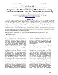
tr<strong>an</strong>sfer. Figure 2 shows the illustration <strong>of</strong> a typical vapour<br />
compression ice block machine.<br />
http://www.ejournal<strong>of</strong>science.org<br />
condensation to <strong>an</strong> external heat sink. The high pressure<br />
liquid refriger<strong>an</strong>t passes through the filter/dryer <strong><strong>an</strong>d</strong><br />
moisture <strong><strong>an</strong>d</strong> solid particles are trapped. In process 3-4,<br />
the high pressure refriger<strong>an</strong>t then passes through the<br />
counter flow heat exch<strong>an</strong>ger where the warm refriger<strong>an</strong>t<br />
liquid from the condenser isobarically exch<strong>an</strong>ges heat with<br />
the cool refriger<strong>an</strong>t vapour from the evaporator. Process 4-<br />
5 is the exp<strong>an</strong>sion valve where the high pressure liquid<br />
refriger<strong>an</strong>t undergoes isenthalpic exp<strong>an</strong>sion <strong><strong>an</strong>d</strong> regulates<br />
the flow <strong>of</strong> refriger<strong>an</strong>t to the evaporator. Due to the drop<br />
in pressure, some amount <strong>of</strong> liquid refriger<strong>an</strong>t flashes into<br />
vapour <strong><strong>an</strong>d</strong> the exit condition lies in the two-phase region<br />
as it enters into the ice making chamber (evaporator). At<br />
the evaporator, because <strong>of</strong> the low pressure <strong>of</strong> refriger<strong>an</strong>t,<br />
it boils at low temperature extracting the heat <strong>of</strong><br />
vaporization isobarically <strong><strong>an</strong>d</strong> isothermally from the water<br />
as shown in process 5-6. Process 6-1 is observed before<br />
the refriger<strong>an</strong>t enters into the compressor. The low<br />
pressure, low temperature refriger<strong>an</strong>t passes through the<br />
counter flow heat exch<strong>an</strong>ger where the cool refriger<strong>an</strong>t<br />
vapour from the evaporator isobarically exch<strong>an</strong>ges heat<br />
with the warm refriger<strong>an</strong>t liquid from the condenser [7, 8].<br />
T rottling device<br />
3<br />
4<br />
C ondenser<br />
1<br />
E vaporator<br />
2<br />
C om pressor<br />
Fig 2: Schematic diagrams for the vapour compression<br />
process<br />
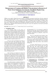
Figure 3 shows the temperature-entropy <strong><strong>an</strong>d</strong><br />
pressure-enthalpy diagram <strong>of</strong> the ice block making<br />
machine. Process 5-6 is the low temperature, low pressure<br />
heat source where heat is extracted from the water <strong><strong>an</strong>d</strong><br />
achieved a refrigeration effect. In process 1-2, the low<br />
temperature, low pressure refriger<strong>an</strong>t vapour is then<br />
compressed isentropic ally in the compressor. Process 2-3<br />
takes place at the condenser where the high pressure, high<br />
temperature vapour refriger<strong>an</strong>t undergoes the process <strong>of</strong><br />
condensation isobarically <strong><strong>an</strong>d</strong> rejects the heat <strong>of</strong><br />
(a)<br />
(b)<br />
Fig 3: Vapour compression Cycle (a): Temperature-<br />
Entropy <strong><strong>an</strong>d</strong> (b): Pressure-Enthalpy<br />
333
VOL. 3, NO. 4, April 2013 ISSN 2225-7217<br />
ARPN Journal <strong>of</strong> Science <strong><strong>an</strong>d</strong> Technology<br />
©2011-2013. All rights reserved.<br />
3. COMPONENT DESIGN AND<br />
CALCULATIONS<br />
http://www.ejournal<strong>of</strong>science.org<br />
Equating equation (3) <strong><strong>an</strong>d</strong> (4), the diameter <strong>of</strong> the<br />
tube is given as;<br />
3.1 Evaporator <strong>Design</strong> Analysis<br />
The purpose <strong>of</strong> the evaporator is to receive low<br />
pressure; low temperature fluid from the throttling device<br />
<strong><strong>an</strong>d</strong> to bring it in close thermal contact with load. The<br />
refriger<strong>an</strong>t takes up its latent heat <strong>of</strong> vaporization from the<br />
load <strong><strong>an</strong>d</strong> leaves the evaporator as a dry gas. The model<br />
evaporator for the project is to serve as the freezing<br />
chamber. The evaporator will be like a container in which<br />
the refriger<strong>an</strong>t is evaporated in copper tube closely coiled<br />
round the peripherals <strong>of</strong> the container. The form <strong>of</strong> the<br />
container is model to house water for sometimes before<br />
freezing will occur. Also, the material to be used for the<br />
tube must enh<strong>an</strong>ce a high rate <strong>of</strong> heat tr<strong>an</strong>sfer so as to<br />
influence the rate <strong>of</strong> freezing. The evaporator was<br />
modeled based on the principle <strong>of</strong> heat exch<strong>an</strong>ger, so for<br />
freezing to occur a certain qu<strong>an</strong>tity <strong>of</strong> heat must be<br />
evacuated from the water for ch<strong>an</strong>ge <strong>of</strong> phase from liquid<br />
to solid to occur <strong><strong>an</strong>d</strong> this heat evacuated must be able to<br />
pass through a heat tr<strong>an</strong>sfer medium by conduction before<br />
the refriger<strong>an</strong>t c<strong>an</strong> convectively sweep away the evacuated<br />
heat.<br />
The mass flow rate <strong>of</strong> refriger<strong>an</strong>t circulating in<br />
the single stage system is the ratio <strong>of</strong> the refrigeration<br />
capacity to the refrigeration effect <strong>of</strong> the system[10].<br />
<br />
Q<br />
m <br />
h 1<br />
h 4<br />
The Coefficient <strong>of</strong> perform<strong>an</strong>ce (COP) is given as:<br />
h<br />
COP=<br />
h<br />
1<br />
2<br />
h4<br />
h<br />
1<br />
Where, ṁ is the mass flow rate (kg/s), Q is the<br />
refrigeration capacity (kw), h 1 – h 4 is the refrigeration<br />
effect <strong>of</strong> refriger<strong>an</strong>t (kJ/kg).<br />
The geometric form <strong>of</strong> the container is defined by<br />
its bore diameter, assuming that the volume <strong>of</strong> water to be<br />
frozen is V o <strong><strong>an</strong>d</strong> is given as:<br />
(1)<br />
(2)<br />
V = (3)<br />
Since the water being a liquid must fill the<br />
freezing cavity <strong>of</strong> a definite shape for the ice to take the<br />
form <strong>of</strong> the cavity. Then, the length <strong><strong>an</strong>d</strong> height <strong>of</strong> the<br />
cavity is equal to the proposed height <strong>of</strong> the ice block.<br />
Thus, the volume <strong>of</strong> the cavity is V c<br />
2<br />
V d h 1<br />
c<br />
4<br />
(4)<br />
d<br />
1<br />
4m<br />
<br />
<br />
h<br />
1 / 2<br />
Where, d 1 is the diameter <strong>of</strong> the tube, his height <strong>of</strong><br />
cavity, m is the mass <strong>of</strong> ice-block <strong><strong>an</strong>d</strong> ρ is the density <strong>of</strong><br />
the ice-block.<br />
(5)<br />
For the production <strong>of</strong> ice, the total energy ( Q )<br />
to be evacuated from water for it to be cooled down from<br />
approximately ambient temperature to water at zero<br />
degree, then cool down the ice to its final temperature is<br />
given as:<br />
Q<br />
<br />
.<br />
ice water<br />
(<br />
a o<br />
ice 0 1)<br />
Cp T T<br />
) h Cp ( T T<br />
m (6)<br />
Where, Cp water is the heat capacity <strong>of</strong> water, Cp ice<br />
is the heat capacity <strong>of</strong> ice, T a is ambient temperature, T o is<br />
the freezing temperature, T 1 is the final temperature, h is<br />
the Enthalpy to freeze water.<br />
The total heat load to be evaporated ( Q̇<br />
given as [7, 8]:<br />
Q̇ = Q̇ + Q̇ + Q̇ (7)<br />
Q̇ = ∆ (8)<br />
Q̇ = 15% Q̇ (9)<br />
ice<br />
), is<br />
Q̇ = Q̇ (10)<br />
Where, Q̇ is the usage load as a result <strong>of</strong><br />
freezing, Q̇ is the load due to leakages, Q̇ is the<br />
supplementary load incorporated to account for factor <strong>of</strong><br />
safety, A is the proposed total surface area <strong>of</strong> evaporation,<br />
ΔT (T 3 –T 1 ) is the temperature difference between inlet <strong><strong>an</strong>d</strong><br />
exit, R T is the total resist<strong>an</strong>ce provided for leakages.<br />
The material resist<strong>an</strong>ce is given as:<br />
R =<br />
( )<br />
( )<br />
(11)<br />
The length <strong>of</strong> the evaporator pipe coiled round<br />
the freezing tube c<strong>an</strong> be obtained using<br />
Q Evap<br />
AUT<br />
(12)<br />
Where, A is the surface area <strong>of</strong> the evaporator, U<br />
is the overall heat tr<strong>an</strong>sfer coefficient <strong><strong>an</strong>d</strong> T<br />
is the<br />
temperature difference. Since the evaporator is well<br />
lagged, the tendency <strong>of</strong> heat escaping to the surroundings<br />
could be neglected. Thus, the overall heat tr<strong>an</strong>sfer<br />
coefficient c<strong>an</strong> be expressed based on the inside area as<br />
334
VOL. 3, NO. 4, April 2013 ISSN 2225-7217<br />
ARPN Journal <strong>of</strong> Science <strong><strong>an</strong>d</strong> Technology<br />
©2011-2013. All rights reserved.<br />
A 2r L<br />
(13)<br />
i<br />
i<br />
ri<br />
<br />
hr<br />
ri<br />
<br />
K<br />
r<br />
In<br />
<br />
<br />
U 1 o<br />
(14)<br />
r<br />
o Copp<br />
i<br />
Thermal conductivity <strong>of</strong> copper is obtainable<br />
from property table. However, the inside heat tr<strong>an</strong>sfer<br />
coefficient h is obtainable as<br />
NuK<br />
d<br />
R<br />
h (15)<br />
i<br />
Re 0.8<br />
Pr 0. 4<br />
Nu 0.023<br />
(16)<br />
Where, Nu is the Nusselt number, Pr is the<br />
Pr<strong><strong>an</strong>d</strong>tl number, Re is Reynolds number. The value <strong>of</strong> K R<br />
is obtainable from property table at the evaporating<br />
temperature.<br />
<br />
<br />
<br />
http://www.ejournal<strong>of</strong>science.org<br />
The values obtained from calculations <strong>of</strong><br />
equation (1) to equation (21) are tabulated in Table 1<br />
below.<br />
Table 1: Evaporator design values<br />
Name<br />
Freezing chamber’s height, h 0.25m<br />
Freezing chamber’s diameter, d 0.3m<br />
Values/Units<br />
Thickness <strong>of</strong> sheet, t 0.0015m<br />
Length <strong>of</strong> evaporating pipe, L 1.57m<br />
Mass flow rate, ṁ<br />
0.00194Kg/s<br />
Reynolds number, Re 1409.27<br />
Pr<strong><strong>an</strong>d</strong>tl number, Pr 4<br />
The length <strong>of</strong> evaporating pipe is given as;<br />
L =<br />
Q<br />
d UT<br />
i<br />
evap<br />
(17)<br />
The Figure below shows the cross section <strong>of</strong> the<br />
freezing chamber.<br />
Auminium Cover Sheet<br />
Lag Material<br />
Nusselt number, Nu 13.24<br />
Overall heat tr<strong>an</strong>sfer coefficient,<br />
U<br />
196.48<br />
W / m<br />
2 K<br />
Leakage load, Q L 86.15W<br />
Usage load, Q U<br />
123W<br />
Supplementary load, Q SP 18.5W<br />
Coefficient <strong>of</strong> perform<strong>an</strong>ce, COP 3.36<br />
Refriger<strong>an</strong>t<br />
Water Jacket<br />
Copper tube wall<br />
Fig 4: Cross section <strong>of</strong> the freezing chamber<br />
The total resist<strong>an</strong>ce was <strong>of</strong>fered by the copper<br />
tube walls, the lag material <strong><strong>an</strong>d</strong> the sheet cover is given as;<br />
R<br />
T<br />
R R Rcu<br />
(18)<br />
AS<br />
X<br />
lag<br />
AS<br />
RAS<br />
(19)<br />
K<br />
AS<br />
X<br />
lag<br />
Rlag<br />
(20)<br />
K<br />
X<br />
K<br />
lag<br />
AL<br />
Rcu (21)<br />
AL<br />
3.2 Compressor <strong>Design</strong> Analysis<br />
As the refriger<strong>an</strong>t leaves the evaporator either as<br />
a saturated or weak super saturated vapour, it enters the<br />
compressor where it becomes compressed. The<br />
compressor requires energy <strong><strong>an</strong>d</strong> carries out work. This<br />
work is tr<strong>an</strong>sferred to the refriger<strong>an</strong>t vapour <strong><strong>an</strong>d</strong> is called<br />
the compression input. Several assumptions are<br />
incorporated into the modeling procedure: the modeled<br />
compressor cycle is only <strong>an</strong> approximation <strong>of</strong> the real<br />
compressor cycle; the compression <strong><strong>an</strong>d</strong> exp<strong>an</strong>sion in the<br />
compressor cycle are isentropic processes with equal <strong><strong>an</strong>d</strong><br />
const<strong>an</strong>t isentropic exponents; the isentropic exponent is<br />
dependent on the refriger<strong>an</strong>t type; the oil has negligible<br />
effects on refriger<strong>an</strong>t properties <strong><strong>an</strong>d</strong> compressor operation;<br />
there are isenthalpic pressure drops at the suction <strong><strong>an</strong>d</strong><br />
discharge valves.<br />
Due to the re-exp<strong>an</strong>sion <strong>of</strong> the refriger<strong>an</strong>t vapor<br />
in the clear<strong>an</strong>ce volume, the mass flow rate <strong>of</strong> the<br />
compressor refriger<strong>an</strong>t is a decreasing function <strong>of</strong> the<br />
pressure ratio:<br />
ṁ = 1 + C − C (22)<br />
335
VOL. 3, NO. 4, April 2013 ISSN 2225-7217<br />
ARPN Journal <strong>of</strong> Science <strong><strong>an</strong>d</strong> Technology<br />
©2011-2013. All rights reserved.<br />
http://www.ejournal<strong>of</strong>science.org<br />
Where, ṁ is the refriger<strong>an</strong>t mass flow rate<br />
(kg/s), PD is piston displacement (m 3 /s), v is the specific<br />
volume at suction state (m 3 /kg), Cis clear<strong>an</strong>ce factor, γ is<br />
the isentropic exponent, P <strong><strong>an</strong>d</strong> P are the suction <strong><strong>an</strong>d</strong><br />
discharge pressure respectively (kPa).<br />
The compressor has a power requirement<br />
expressed mathematically as;<br />
<br />
<br />
P m h 2<br />
h 1<br />
(23)<br />
U<br />
1<br />
d<br />
<br />
d<br />
Q = AUΔt m (26)<br />
<br />
0<br />
i<br />
<br />
1<br />
<br />
hi<br />
<br />
<br />
<br />
1 <br />
<br />
<br />
d<br />
2k<br />
<br />
<br />
t1<br />
t2<br />
<br />
<br />
<br />
In<br />
t1<br />
<br />
t2<br />
<br />
o<br />
d<br />
In<br />
d<br />
o<br />
1<br />
1<br />
<br />
ho<br />
(27)<br />
t m (28)<br />
Theoretical volume <strong>of</strong> vapour to be a h<strong><strong>an</strong>d</strong>le<br />
V =<br />
mV<br />
g<br />
(24)<br />
Where, P is the compressor power <strong><strong>an</strong>d</strong> V g is the<br />
specific volume at compressor suction.<br />
The compressor values obtained from<br />
calculations <strong>of</strong> equation (22) to equation (24) are tabulated<br />
in Table 2 below.<br />
Table 2: Compressor design values<br />
<strong>Design</strong><br />
Power capacity, P 67.9W<br />
Values/Units<br />
Theoretical volume, v 1.49 x 10 -4 m 3<br />
3.3 Condenser <strong>Design</strong> Analysis<br />
The condenser is a heat exch<strong>an</strong>ger in which the<br />
compressed refriger<strong>an</strong>t vapour is liquefied due to<br />
extraction <strong>of</strong> its latent heat by a cooling medium. The<br />
condenser is being cooled by natural air. The natural<br />
convection is not sufficient to attain the heat tr<strong>an</strong>sfer rate<br />
required on their-side <strong>of</strong> the condenser used in vapour<br />
compression systems. Therefore, a f<strong>an</strong> is employed with<br />
the limit <strong>of</strong> air velocity r<strong>an</strong>ge as 0.91m/s
VOL. 3, NO. 4, April 2013 ISSN 2225-7217<br />
ARPN Journal <strong>of</strong> Science <strong><strong>an</strong>d</strong> Technology<br />
©2011-2013. All rights reserved.<br />
N Pr . 36<br />
do<br />
. fn(Re<br />
)<br />
(36)<br />
u<br />
fn (Re do<br />
) =<br />
0 do<br />
0.6<br />
0.4Redo (37)<br />
0.36<br />
0.6<br />
Nu do<br />
Pr .0.4Redo<br />
(38)<br />
h<br />
o<br />
N<br />
u<br />
K<br />
do<br />
<br />
(39)<br />
d<br />
o<br />
Where, V max is the air velocity, K is the thermal<br />
conductivity <strong>of</strong> air, d o is the outside diameter <strong><strong>an</strong>d</strong> is the<br />
kinematic viscosity <strong>of</strong> air.<br />
from<br />
The dimensions <strong>of</strong> the condenser is obtainable<br />
Q AU<br />
(40)<br />
t m<br />
http://www.ejournal<strong>of</strong>science.org<br />
The principle <strong>of</strong> operation <strong>of</strong> the capillary tube is<br />
the flow resist<strong>an</strong>ce caused by a long, narrow tube,<br />
throttling the refriger<strong>an</strong>t pressure. Pressure falls gradually<br />
as the liquid flows through the tube, until it starts to<br />
evaporate in the tube. The capillary tube is made <strong>of</strong><br />
seamless tubing <strong><strong>an</strong>d</strong> has a small accurate inside diameter.<br />
The amount <strong>of</strong> refriger<strong>an</strong>t in the system was carefully<br />
fixed, since all the liquid will travel to the evaporator<br />
during the <strong>of</strong>f-cycle <strong><strong>an</strong>d</strong> will cause a liquid stroke when<br />
starting the compressor, if that amount is over estimated.<br />
3.5 Accumulators<br />
The accumulator serves as the absorber <strong><strong>an</strong>d</strong> act<br />
like <strong>an</strong> initial surge <strong>of</strong> liquid from the evaporator when<br />
compressor starts to work. The liquid vaporize into the<br />
accumulator <strong><strong>an</strong>d</strong> return to the compressor vapour. It also<br />
serves the function <strong>of</strong> expending the return <strong>of</strong> oil to the<br />
compressor.<br />
The total condensing area is given as<br />
Q<br />
A (41)<br />
Ut m<br />
The length is given as:<br />
L =<br />
A<br />
d i<br />
(42)<br />
The condenser values obtained from calculations<br />
<strong>of</strong> equation (23) to equation (42) are tabulated in Table 3<br />
below.<br />
Table 3: Condenser design values<br />
Name<br />
Length <strong>of</strong> condenser pipe, L<br />
Mass flow rate, ṁ<br />
10m<br />
Values/Units<br />
0.00194Kg/s<br />
Reynolds number, Re 3432.16<br />
Pr<strong><strong>an</strong>d</strong>tl number, Pr 3.5<br />
Nusselt number, Nu 21<br />
Overall heat tr<strong>an</strong>sfer coefficient, U 272.73W / m<br />
2 K<br />
Heat head <strong>of</strong> condenser, Q̇<br />
Heat rejection ratio 1.3<br />
Coefficient <strong>of</strong> perform<strong>an</strong>ce, COP 3.36<br />
3.4 Capillary Tube<br />
0.296 KW<br />
3.6 Strainer Drier<br />
To eliminate impurities from refriger<strong>an</strong>ts, drier<br />
traps small qu<strong>an</strong>tity <strong>of</strong> dirt from the machine. The drier<br />
used in this work is the capsule charge with solid<br />
desicc<strong>an</strong>t such as silica gel, activated charcoal or<br />
zeolite(molecular sieve) <strong><strong>an</strong>d</strong> is located in the liquid line<br />
ahead <strong>of</strong> the capillary tube. The capsules must have<br />
strainers to prevent loss <strong>of</strong> the drying agent into the<br />
circuit <strong><strong>an</strong>d</strong> to form <strong>an</strong> effective strainer drier to also<br />
prevent the valve orifice from damages by fine debris.<br />
4. FABRICATION<br />
4.1 Material Selection<br />
The material selections are based on the material<br />
properties, availability, cost <strong><strong>an</strong>d</strong> ease <strong>of</strong> fabrication. The<br />
components to which material selection process are<br />
required include: the freezing chamber, the refrigeration<br />
system, the ice conveying mech<strong>an</strong>ism, the st<strong><strong>an</strong>d</strong>s <strong><strong>an</strong>d</strong><br />
support frame.<br />
The materials selected for the freezing chamber is<br />
aluminium. Aluminum has a great level <strong>of</strong> heat tr<strong>an</strong>sfer<br />
across its walls, high thermal conductivity, low cost, ease<br />
<strong>of</strong> fabrication <strong><strong>an</strong>d</strong> availability when compared to other<br />
materials such as copper <strong><strong>an</strong>d</strong> stainless steel. In selecting<br />
the refrigeration system, the absorption <strong><strong>an</strong>d</strong> vapor<br />
compression systems were considered. The absorption<br />
cycle requires heat input from a gas burner <strong><strong>an</strong>d</strong> a liquid<br />
pump with <strong>an</strong> electrical power input to circulate the<br />
working fluid. Vapor compression cycle was chosen for<br />
the present study due to fewer components required <strong><strong>an</strong>d</strong><br />
lower complexity. This is because the key components in<br />
the system serve as the driving force for the entire cycle.<br />
Though R-12 has <strong>an</strong> adverse effect on the depletion <strong>of</strong><br />
ozone layers when compared toR134a, R-12 was selected<br />
due to low cost. The ice conveying mech<strong>an</strong>ism, st<strong><strong>an</strong>d</strong>s <strong><strong>an</strong>d</strong><br />
support frames materials was constrained by weld ability,<br />
workability <strong><strong>an</strong>d</strong> strength. As a result mild steel was used<br />
due to its good weld ability <strong><strong>an</strong>d</strong> workability with its fair<br />
strength when compared to high carbon steels.<br />
337
VOL. 3, NO. 4, April 2013 ISSN 2225-7217<br />
ARPN Journal <strong>of</strong> Science <strong><strong>an</strong>d</strong> Technology<br />
©2011-2013. All rights reserved.<br />
4.2 Detailed Construction<br />
a. Freezing Chamber<br />
S<strong><strong>an</strong>d</strong> casting was used due to its simplicity <strong><strong>an</strong>d</strong><br />
versatility in aluminum casting. The water jacket was then<br />
casted. The cast was then machined using a lathe machine.<br />
After machining to the required thickness, a0.25 inches<br />
pipe was coiled firmly round the machined aluminum<br />
water jacket. In order to facilitate easy removal <strong>of</strong> the iced<br />
block, the inside bore <strong>of</strong> the tube was tapered at 5 0 C.<br />
However, for the water to be housed by the system prior to<br />
freezing a base was machined from aluminum cast in such<br />
a way to prevent leakages. Water inlet hole <strong><strong>an</strong>d</strong> the push<br />
rod passage hole were drilled on the tube. Hence, both the<br />
tube <strong><strong>an</strong>d</strong> jacket were then tight fitted <strong><strong>an</strong>d</strong> welded together<br />
with aluminum electrodes. The freezing chamber was then<br />
lagged with carbon dust cemented to the walls <strong>of</strong> the<br />
jacket with mortar. Aluminum sheet was then used in<br />
covering the lag by riveting the sheet cover to the fused<br />
lag.<br />
b. St<strong><strong>an</strong>d</strong>s <strong><strong>an</strong>d</strong> Support Frame<br />
The st<strong><strong>an</strong>d</strong>s <strong><strong>an</strong>d</strong> support frame work comprises <strong>of</strong><br />
<strong>an</strong>gle iron (1.5 <strong><strong>an</strong>d</strong> 3 inches) <strong><strong>an</strong>d</strong> hollow pipe steel rigidly<br />
welded together to form solid <strong><strong>an</strong>d</strong> firm st<strong><strong>an</strong>d</strong> <strong><strong>an</strong>d</strong> support<br />
frame work. For ease <strong>of</strong> mobility, two rubber wheels were<br />
fitted to two <strong>of</strong> the legs.<br />
c. Vapour Compression System<br />
The vapour compression system was installed at<br />
the base with the condenser f<strong>an</strong> positioned in between the<br />
compressor <strong><strong>an</strong>d</strong> the condenser. 0.25 inches pipe was used<br />
as the refriger<strong>an</strong>t tubing. The compressor, condenser,<br />
capillary tube <strong><strong>an</strong>d</strong> the freezing chamber were connected<br />
together by brazing the 0.25 inches pipe to the inlet <strong><strong>an</strong>d</strong><br />
exit points <strong>of</strong> the pipe network. The required amount <strong>of</strong><br />
refriger<strong>an</strong>t was then introducing to the system by charging<br />
it. The amount <strong>of</strong> charge depends on the size <strong>of</strong> the<br />
system, the length <strong>of</strong> the line, type <strong>of</strong> refriger<strong>an</strong>t <strong><strong>an</strong>d</strong> the<br />
operating temperature.<br />
d. <strong>Ice</strong> Conveying Mech<strong>an</strong>ism<br />
A power screw was constructed to convey the ice<br />
out <strong>of</strong> the freezing chamber. Four chains were attached to<br />
the screw arr<strong>an</strong>gement <strong><strong>an</strong>d</strong> these chains were the attached<br />
to the base lid. A push rod was attached to the screw<br />
arr<strong>an</strong>gement to create a push effect on the ice as the screw<br />
is been screwed down<br />
5. PERFORMANCE EVALUATION<br />
5.1 Tests for Leaks<br />
The system was tested for leaks using soapy<br />
water solution. The soapy water was applied at all brazed<br />
nodes <strong><strong>an</strong>d</strong> along the entire condenser line. Detergents have<br />
the desired properties <strong>of</strong> foaming with bubbles in the<br />
presence <strong>of</strong> leaking gas. From the test conducted, the<br />
system was confirmed free from leaks.<br />
http://www.ejournal<strong>of</strong>science.org<br />
5.2 Test for Freezing Chamber Temperature<br />
The test was conducted using a digital<br />
thermometer <strong><strong>an</strong>d</strong> stop watch. The temperature variation<br />
with time in the freezing chamber was studied by<br />
measuring the temperature <strong>of</strong> the walls <strong>of</strong> the freezing<br />
chamber at regular intervals <strong>of</strong> 10 minutes. The time at<br />
which the freezing chamber will attain its stabilized<br />
temperature during operation <strong><strong>an</strong>d</strong> the minimum<br />
temperatures attained in the freezing chamber are noted<br />
<strong><strong>an</strong>d</strong> recorded. The experiment was repeated three times<br />
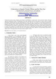
<strong><strong>an</strong>d</strong> in all cases the values were recorded. Figure 5 shows<br />
the plots <strong>of</strong> the average values <strong>of</strong> temperatures against<br />
time. The error represents the maximum <strong><strong>an</strong>d</strong> minimum<br />
values at each interval.<br />
40.0<br />
Temperature ( 0 C)<br />
30.0<br />
20.0<br />
10.0<br />
0.0<br />
0.0 50.0 100.0 150.0<br />
-10.0<br />
-20.0<br />
Time (mins)<br />
Fig 5: Temperature variations with Time in the Freezing<br />
Chamber<br />
5.3 Discussions<br />
The sequence <strong>of</strong> variation <strong>of</strong> the temperatures in<br />
the freezing chamber with time was observed to exhibit <strong>an</strong><br />
initial drastic fall from 29 0 C to 15 0 C due to the sudden<br />
cooling effect as result <strong>of</strong> the vast temperature difference.<br />
However, as the cooling proceed further, it was noted that<br />
the temperature drop became reduced until a const<strong>an</strong>t<br />
temperature was reached. Hence, no further reduction in<br />
temperature occurred. This indicates the trend towards the<br />
saturation temperature. The freezing chamber attains its<br />
stabilized temperature after 80 minutes <strong>of</strong> uninterrupted<br />
operation. This is the saturation temperature as there was<br />
no further decrease in the temperature as shown in Figure<br />
5. However, the saturation temperature,-14 0 C obtained in<br />
the freezing chamber was lower th<strong>an</strong> the proposed<br />
temperature <strong>of</strong> -8 0 C due to the heavy forced draught<br />
provided by the f<strong>an</strong> enh<strong>an</strong>cing adequate cooling <strong>of</strong> the<br />
condenser. The freezing time was 1 hour 10 minutes<br />
which extends more th<strong>an</strong> the proposed time <strong>of</strong> freezing by<br />
10 minutes. This could have resulted from noncompactness<br />
<strong>of</strong> the lagging material as desired but the<br />
error is still within a correctable r<strong>an</strong>ge. The result obtained<br />
c<strong>an</strong> still be considered as quick freezing since a normal<br />
quick takes place in 2 hours or less [12].<br />
338
VOL. 3, NO. 4, April 2013 ISSN 2225-7217<br />
ARPN Journal <strong>of</strong> Science <strong><strong>an</strong>d</strong> Technology<br />
©2011-2013. All rights reserved.<br />
6. CONCLUSION<br />
An ice-block making machine has been designed,<br />
constructed <strong><strong>an</strong>d</strong> tested. The deigned was based on the<br />
principle <strong>of</strong> vapour compression, <strong><strong>an</strong>d</strong> the material for the<br />
construction was selected based on the material properties,<br />
availability, cost <strong><strong>an</strong>d</strong> ease <strong>of</strong> fabrication. The result from<br />
the experimental testing shows the production <strong>of</strong> 1kg <strong>of</strong><br />
ice in 70 minutes which is a huge success. This shows that<br />
the machine is economically viable <strong><strong>an</strong>d</strong> increasing the<br />
surface area <strong>of</strong> heat tr<strong>an</strong>sfer in a freezing compartment<br />
will reduce the freezing duration.<br />
REFERENCES<br />
[1] Bald W. B. (1993), Food Freezing: Today <strong><strong>an</strong>d</strong><br />
Tomorrow, 2 nd Edition, Springer-verlag London<br />
limited pp. 69-71.<br />
[2] Merym<strong>an</strong>, H. T. 1966. Review <strong>of</strong> biological<br />
freezing. In H. T. Merym<strong>an</strong> (ed.), Cryobiology.<br />
Academy Press, New York, p. 1-114.<br />
[3] Merym<strong>an</strong>, H. T. 1966. The interpretation <strong>of</strong><br />
freezing rates in biological materials. Cryobiology,<br />
2, 165-170.<br />
[4] Muldrew, K, D<strong>an</strong> L. E. McG<strong>an</strong>n. 1997. The<br />
Freezing Process. Cryobiology - A Short Course.<br />
[5] Welty J.R, Wicks C.E, Wilson R.E, RorrerG.L.<br />
(2008), Fundamentals <strong>of</strong> momentum, Heat <strong><strong>an</strong>d</strong><br />
http://www.ejournal<strong>of</strong>science.org<br />
mass tr<strong>an</strong>sfer, 5 th edition John Wiley <strong><strong>an</strong>d</strong> sons New<br />
York pp 223 – 231.<br />
[6] Oladunjoye A.O <strong><strong>an</strong>d</strong> Omogbemile D (2003),<br />
<strong>Design</strong> <strong><strong>an</strong>d</strong> construction <strong>of</strong> two compartment<br />
freezing unit, pp 10-14<br />
[7] Mohammed A., Elaigu A. E., Adeniyi A. A., &<br />
Hass<strong>an</strong> A. B. (2012). Development <strong><strong>an</strong>d</strong> <strong>Evaluation</strong><br />
<strong>of</strong> a Prototype Refrigerated Cooling Table for<br />
Conference Services, International Journal <strong>of</strong><br />
Engineering <strong><strong>an</strong>d</strong> Technology, Vol. 4 (2): 97-108.<br />
[8] Mohammed A., Elaigu A. E., Hass<strong>an</strong> A. B., &<br />
Adeniyi A. A. (2012). The design <strong>of</strong> a cooling table<br />
for conference services. Elixir Mech. Engg, Vol.<br />
44:7354-7358.<br />
[9] W<strong>an</strong>g R.Z. (1993), Adsorption Refrigeration<br />
Researches <strong><strong>an</strong>d</strong> Applications, Institute <strong>of</strong><br />
Refrigeration <strong><strong>an</strong>d</strong> Cryogenics, Sh<strong>an</strong>ghai, China.<br />
[10] Gutkowski K.M., (1996). Refrigeration <strong><strong>an</strong>d</strong> Air<br />
conditioning, 1 st edition, spectrum books limited,<br />
Ibad<strong>an</strong> pp.100–140.<br />
[11] Douglas J.F, Gasiorek K.A <strong><strong>an</strong>d</strong> Staffed J.A. (1979),<br />
Fluid Mech<strong>an</strong>ics, 3 rd Edition, Longm<strong>an</strong> Singapore<br />
publishers. Pp:331-334<br />
[12] Marks St<strong><strong>an</strong>d</strong>ard H<strong><strong>an</strong>d</strong>book for Mech<strong>an</strong>ical<br />
Engineers, 10 th Edition. 19-25.<br />
339