OPERATION MANUAL - Decision-Computer Merz
OPERATION MANUAL - Decision-Computer Merz
OPERATION MANUAL - Decision-Computer Merz

Create successful ePaper yourself
Turn your PDF publications into a flip-book with our unique Google optimized e-Paper software.
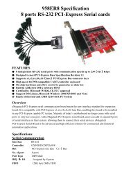
Operations Manual USB 16 Channel Photo<br />
Isolator Input Board<br />
Operations Manual USB 16 Channel Photo<br />
Isolator Input Board<br />
SMARTLAB<br />
USB 16 CHANNELS PHOTO<br />
ISOLATOR INPUT<br />
<strong>OPERATION</strong> <strong>MANUAL</strong><br />
CHAPTERS<br />
1. Introduction…………………………………..……1<br />
2. Hardware Configuration…………………..…….... 4<br />
3. Diagnostic under Windows/XP …………………10<br />
4. Programming under Windows/XP and Linux……10<br />
APPENDICES<br />
A. Warranty Information……………………………11<br />
B. Data Sheet…………..……………………………13<br />
<strong>Decision</strong> <strong>Computer</strong> Int’l. Co., Ltd.<br />
DECISION <strong>Computer</strong> International i - i -<br />
ii DECISION <strong>Computer</strong> International
Operations Manual USB 16 Channel Photo<br />
Isolator Input Board<br />
CHAPTER 1<br />
INTRODUCTION<br />
The USB 16 channels photo isolator input card provides 16<br />
photo couple digital input channels, and one<br />
RS232/RS422/RS485 port functions, which allow the digital<br />
input signals to be completely floated and prevent the ground<br />
loop and COM communication.<br />
The USB 16 channels photo isolator input card provides one<br />
asynchronous serial communication ports (RS232 or RS422 or<br />
RS485), which link the computer and serial peripheral devices<br />
such as terminals, modems, serial printers, plotters, ... etc.<br />
The USB 16 channels photo isolator input card provides Plug<br />
and Play (PnP) features, it is a programmable I/O interface card<br />
for PC/486, Pentium, or compatibles. The on board high speed<br />
8051 uC provides USB functions run at 12Mbps full speed or<br />
1.5Mbps low speed.<br />
The features of USB 16 channels photo isolator input<br />
card are:<br />
• USB 2.0with Plug and Play (PnP) features.<br />
• High speed 8051 uC core.<br />
• Support USB ID selection to identify USB device.<br />
• Support 16 photo couple input channels and one<br />
RS232/RS422/RS485 port functions.<br />
• Allow the photo input signals to be completely floated<br />
and prevent the ground loops.<br />
• 16 LED correspond to 16 input ports activation status.<br />
• By using PC817 photo couple chips.<br />
Operations Manual USB 16 Channel Photo<br />
Isolator Input Board<br />
• Allow to connect RS232 or RS422/RS485 extension<br />
board with DB9 connector.<br />
• Power supplied from USB or external DC +5V/3A.<br />
• 5000V isolation voltage.<br />
• Maximum load voltage is 30V.<br />
• Maximum 50mA forward input current.<br />
• Input voltage range from 0V to 30V.<br />
• Activation voltage of photo input:<br />
When short jumpers (input range from 0 to 20V DC)<br />
0 to 3.3V inactive<br />
4.5 to 20V active<br />
When open jumpers (input range from 0 to 30V DC)<br />
0 to 17.6V inactive<br />
18 to 30V active<br />
• Suitable for Linux, MS/WINDOWS, ... etc.<br />
• Operating temperature range from 0 to 33C.<br />
• Relative humidity rage from 0 to 90%.<br />
PACKAGE CONTENTS:<br />
• SMARTLAB USB 16 channels photo input board.<br />
• USB cable.<br />
• <strong>Decision</strong> Studio and User’s manual CD.<br />
• Two Different Connecter Types can be selected:<br />
Standard: European P.C.B type terminal blocks<br />
Professional: Pluggable terminal blocks<br />
Optional<br />
• Extension board with DB9 : RS232 or RS422/485<br />
• PCB Carrier<br />
DECISION <strong>Computer</strong> International 1 - 1 -<br />
2<br />
DECISION <strong>Computer</strong> International
Operations Manual USB 16 Channel Photo<br />
Isolator Input Board<br />
•<br />
Operations Manual USB 16 Channel Photo<br />
Isolator Input Board<br />
CHAPTER 2<br />
HARDWARE CONFIGURATION<br />
Before you use the USB 16 channels photo couple input card,<br />
please ensure that the jumpers and switches setting. The proper<br />
jumper and switches settings for the 16 channels photo couple<br />
input card are described in the following.<br />
2.1 Switch Settings<br />
1. S1 Reset<br />
The S1 switch is used to reset 8051, the signal assignments are<br />
shown in the following.<br />
2. S2 USB ID<br />
Pin Signals<br />
3,4 Reset SW+<br />
1,2 Reset SW-<br />
DECISION <strong>Computer</strong> International 3 - 3 -<br />
4<br />
DECISION <strong>Computer</strong> International
Operations Manual USB 16 Channel Photo<br />
Isolator Input Board<br />
The S2 switch is used to identify USB card ID. Please set<br />
different card ID to each card (do not duplicate card ID setting).<br />
1 2 3 4 Card ID<br />
ON ON ON ON --<br />
OFF ON ON ON 14<br />
ON OFF ON ON 13<br />
OFF OFF ON ON 12<br />
ON ON OFF ON 11<br />
OFF ON OFF ON 10<br />
ON OFF OFF ON 9<br />
OFF OFF OFF ON 8<br />
ON ON ON OFF 7<br />
OFF ON ON OFF 6<br />
ON OFF ON OFF 5<br />
OFF OFF ON OFF 4<br />
ON ON OFF OFF 3<br />
OFF ON OFF OFF 2<br />
ON OFF OFF OFF 1<br />
OFF OFF OFF OFF 0<br />
3. Down load revised firmware<br />
When the S2 switch is set to ON ON ON ON status, means<br />
down load revised firmware. please follow the steps shown in<br />
the following:<br />
1. Set S2 to ON ON ON ON.<br />
2. Run USBBootloader program to down load revised firmware.<br />
Operations Manual USB 16 Channel Photo<br />
Isolator Input Board<br />
2.2 Jumper Settings<br />
Input Voltage Range Selection (JP1 to JP16)<br />
1 2<br />
. .<br />
JP1 to JP16 are used to select input voltage range. The JP1 is<br />
used to select photo couple input channel 0, and JP2 is used to<br />
select photo couple input channel 1, … etc. When short the<br />
jumper, the input voltage range from 0 to 20V, and the active<br />
voltage form 4.5 to 20V. When open the jumper, the input<br />
voltage range from 0 to 30V, and the active voltage from 18 to<br />
30V.<br />
Jumper Input Voltage Inactive Voltage Active Voltage<br />
open 0 to 30V 0 to 17.6V 18 to 30V<br />
short 0 to 20V 0 to 3.3V 4.5 to 20V<br />
2.3 USB Connector<br />
1. USB Connector<br />
The USB connector is connected to<br />
computer USB port by using USB cable.<br />
2.4 LED Status<br />
1. LED1<br />
DECISION <strong>Computer</strong> International 5 - 5 -<br />
6<br />
DECISION <strong>Computer</strong> International
Operations Manual USB 16 Channel Photo<br />
Isolator Input Board<br />
The LED1 is an indicator to show the power is supplied<br />
normally.<br />
2. LED2<br />
The LED2 is an indicator to warning the USB link status.<br />
When it lights, it means USB connection works normally,<br />
otherwise it is fail.<br />
2.5 Connector and Jumper for Serial Communication<br />
1. The connector of serial communication(J2)<br />
To use RS422/RS485/RS232, please connect J2 to extension<br />
board by 10 pins flat cable. (Optional)<br />
2. Enable Serial Port (J3)<br />
1 2<br />
. .<br />
J3 is used enable serial port communication, when short the J3,<br />
means enable serial port, otherwise, when open the J3, the<br />
serial port communication is disable.<br />
Operations Manual USB 16 Channel Photo<br />
Isolator Input Board<br />
2.6 Connector Assignments<br />
The photo isolator input signal pin assignments are shown in<br />
the below.<br />
Pin Signal Description<br />
1<br />
2<br />
3<br />
4<br />
5<br />
6<br />
7<br />
8<br />
IN0+<br />
IN0-<br />
IN1+<br />
IN1-<br />
IN2+<br />
IN2-<br />
IN3+<br />
IN3-<br />
Opto-isolator Ch. 00 + Input<br />
Opto-isolator Ch. 00 - Input<br />
Opto-isolator Ch. 01 + Input<br />
Opto-isolator Ch. 01 - Input<br />
Opto-isolator Ch. 02 + Input<br />
Opto-isolator Ch. 02 - Input<br />
Opto-isolator Ch. 03 + Input<br />
Opto-isolator Ch. 03 – Input<br />
Pin Signal Description<br />
1<br />
2<br />
3<br />
4<br />
5<br />
6<br />
7<br />
8<br />
9<br />
10<br />
IN4+<br />
IN4-<br />
IN5+<br />
IN5-<br />
IN6+<br />
IN6-<br />
IN7+<br />
IN7-<br />
SGND<br />
EXT +5V<br />
Opto-isolator Ch. 04 + Input<br />
Opto-isolator Ch. 04 - Input<br />
Opto-isolator Ch. 05 + Input<br />
Opto-isolator Ch. 05 - Input<br />
Opto-isolator Ch. 06 + Input<br />
Opto-isolator Ch. 06 - Input<br />
Opto-isolator Ch. 07 + Input<br />
Opto-isolator Ch. 07 – Input<br />
Signal Ground<br />
External DC +5V 3A Power In<br />
DECISION <strong>Computer</strong> International 7 - 7 -<br />
8<br />
DECISION <strong>Computer</strong> International
Operations Manual USB 16 Channel Photo<br />
Isolator Input Board<br />
Pin Signal Description<br />
1<br />
2<br />
3<br />
4<br />
5<br />
6<br />
7<br />
8<br />
IN8+<br />
IN8-<br />
IN9+<br />
IN9-<br />
IN10+<br />
IN10-<br />
IN11+<br />
IN11-<br />
Opto-isolator Ch. 08 + Input<br />
Opto-isolator Ch. 08 - Input<br />
Opto-isolator Ch. 09 + Input<br />
Opto-isolator Ch. 09 -Input<br />
Opto-isolator Ch. 10 + Input<br />
Opto-isolator Ch. 10 - Input<br />
Opto-isolator Ch. 11 + Input<br />
Opto-isolator Ch. 11 – Input<br />
Operations Manual USB 16 Channel Photo<br />
Isolator Input Board<br />
CHAPTER 3<br />
DIAGNOSTIC UNDER WINDOWS/XP<br />
USB Test Program.exe is a diagnostic program to test your<br />
USB devices under Windows/XP.<br />
User can get USB Test Program.exe programs from <strong>Decision</strong><br />
Studio CD.<br />
Pin Signal Description<br />
1<br />
2<br />
3<br />
4<br />
5<br />
6<br />
7<br />
8<br />
IN12+<br />
IN12-<br />
IN13+<br />
IN13-<br />
IN14+<br />
IN14-<br />
IN15+<br />
IN15-<br />
Opto-isolator Ch. 12 + Input<br />
Opto-isolator Ch. 12 - Input<br />
Opto-isolator Ch. 13 + Input<br />
Opto-isolator Ch. 13 - Input<br />
Opto-isolator Ch. 14 + Input<br />
Opto-isolator Ch. 14 - Input<br />
Opto-isolator Ch. 15 + Input<br />
Opto-isolator Ch. 15 – Input<br />
CHAPTER 4<br />
SOFTWARE PROGRAMMING UNDER<br />
WINDOWS/XP AND LINUX<br />
Under Windows, we provide function library and dll file for<br />
users to program the device in supported language. You can<br />
find manual “USBDII_Manual.pdf” and demo code in<br />
VB/VC/Delphi from <strong>Decision</strong> Studio CD.<br />
Under Linux, we provide .c source to allow user directly to<br />
access device. You can find manual and example in “dcihid-<br />
0.5.1.tgz”.<br />
DECISION <strong>Computer</strong> International 9 - 9 -<br />
10 DECISION <strong>Computer</strong> International
Operations Manual USB 16 Channel Photo<br />
Isolator Input Board<br />
A.1 Copyright<br />
APPENDIX A<br />
WARRANTY INFORMATION<br />
Copyright DECISION COMPUTER INTERNATIONAL CO.,<br />
LTD. All rights reserved. No part of SmartLab software and<br />
manual may be produced, transmitted, transcribed, or translated<br />
into any language or computer language, in any form or by any<br />
means, electronic, mechanical, magnetic, optical, chemical,<br />
manual, or otherwise, without the prior written permission of<br />
DECISION COMPUTER INTERNATIONAL CO., LTD.<br />
Each piece of SmartLab package permits user to use SmartLab<br />
only on a single computer, a registered user may use he<br />
program on a different computer, but may not use the program<br />
on more than one computer at the same time.<br />
Corporate licensing agreements allow duplication and<br />
distribution of specific number of copies within the licensed<br />
institution. Duplication of multiple copies is not allowed<br />
except through execution of a licensing agreement. Welcome<br />
call for details.<br />
A.2 Warranty Information<br />
SmartLab warrants that for a period of one year from the date<br />
of purchase (unless otherwise specified in the warranty card)<br />
that the goods supplied will perform according to the<br />
specifications defined in the user manual. Furthermore that<br />
the SmartLab product will be supplied free from defects in<br />
Operations Manual USB 16 Channel Photo<br />
Isolator Input Board<br />
materials and workmanship and be fully functional under<br />
normal usage.<br />
In the event of the failure of a SmartLab product within<br />
the specified warranty period, SmartLab will, at its option,<br />
replace or repair the item at no additional charge. This<br />
limited warranty does not cover damage resulting from<br />
incorrect use, electrical interference, accident, or modification<br />
of the product.<br />
All goods returned for warranty repair must have the serial<br />
number intact. Goods without serial numbers attached will not<br />
be covered by the warranty.<br />
The purchaser must pay transportation costs for goods returned.<br />
Repaired goods will be dispatched at the expense of SmartLab.<br />
To ensure that your SmartLab product is covered by the<br />
warranty provisions, it is necessary that you return the<br />
Warranty card.<br />
Under this Limited Warranty, SmartLab's obligations will be<br />
limited to repair or replacement only, of goods found to be<br />
defective a specified above during the warranty period.<br />
SmartLab is not liable to the purchaser for any damages or<br />
losses of any kind, through the use of, or inability to use, the<br />
SmartLab product. SmartLab reserves the right to determine<br />
what constitutes warranty repair or replacement.<br />
Return Authorization: It is necessary that any returned goods<br />
are clearly marked with an RA number that has been issued by<br />
SmartLab. Goods returned without this authorization will not<br />
be attended to.<br />
DECISION <strong>Computer</strong> International 11 - 11 -<br />
12 DECISION <strong>Computer</strong> International
Operations Manual USB 16 Channel Photo<br />
Isolator Input Board<br />
Operations Manual USB 16 Channel Photo<br />
Isolator Input Board<br />
APPENDIX B<br />
DATA SHEET<br />
DECISION <strong>Computer</strong> International 13 - 13 -<br />
14 DECISION <strong>Computer</strong> International
Operations Manual USB 16 Channel Photo<br />
Isolator Input Board<br />
Operations Manual USB 16 Channel Photo<br />
Isolator Input Board<br />
DECISION <strong>Computer</strong> International 15 - 15 -<br />
16 DECISION <strong>Computer</strong> International