92-24161-16 Rev. 20 RGRA, RGRB, RGRS, RGTS ... - Rheemote.Net
92-24161-16 Rev. 20 RGRA, RGRB, RGRS, RGTS ... - Rheemote.Net
92-24161-16 Rev. 20 RGRA, RGRB, RGRS, RGTS ... - Rheemote.Net

Create successful ePaper yourself
Turn your PDF publications into a flip-book with our unique Google optimized e-Paper software.
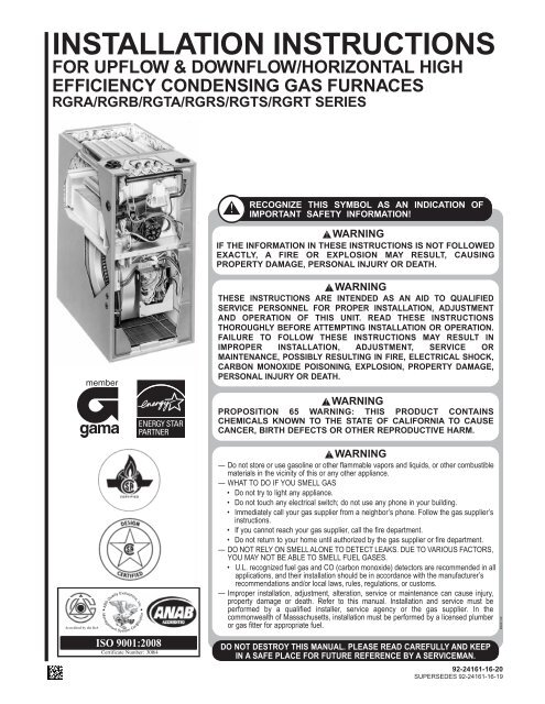
INSTALLATION INSTRUCTIONS<br />
FOR UPFLOW & DOWNFLOW/HORIZONTAL HIGH<br />
EFFICIENCY CONDENSING GAS FURNACES<br />
<strong>RGRA</strong>/<strong>RGRB</strong>/RGTA/<strong>RGRS</strong>/<strong>RGTS</strong>/RGRT SERIES<br />
U.L. recognized fuel gas and CO (carbon monoxide) detectors are recommended in all<br />
applications, and their installation should be in accordance with the manufacturer’s<br />
recommendations and/or local laws, rules, regulations, or customs.<br />
ISO 9001:<strong>20</strong>08<br />
<strong>92</strong>-<strong>24<strong>16</strong>1</strong>-<strong>16</strong>-<strong>20</strong><br />
SUPERSEDES <strong>92</strong>-<strong>24<strong>16</strong>1</strong>-<strong>16</strong>-19
INSTALLATION CHECK LIST<br />
REFER TO INSTALLATION INSTRUCTIONS<br />
GAS SUPPLY<br />
ELECTRICAL<br />
Adequate pipe size<br />
Correct supply pressure (during furnace operation)<br />
Manifold pressure<br />
No gas leaks<br />
L.P. Kit Number (if applicable)<br />
115 V.A.C. supply (Single Circuit)<br />
Polarity observed<br />
Furnace properly grounded<br />
Adequate wire size<br />
FURNACE INSTALLATION<br />
Adequate clearance to combustibles<br />
Adequate clearance for service (at front)<br />
DUCT STATIC PRESSURE<br />
in. w.c. on heating speed<br />
in. w.c. on cooling speed<br />
Air temperature rise<br />
CONDENSATE LINE<br />
Trap filled with water<br />
Vented<br />
Sloped toward drain<br />
Condensate drain line hoses connected<br />
and clamped<br />
Freeze protection (if necessary)<br />
VENTING – DIRECT VENT<br />
in. diameter – intake pipe<br />
in. diameter – exhaust pipe<br />
ft. of pipe – intake air<br />
no. of elbows – intake air<br />
ft. of pipe – exhaust pipe<br />
TERMINATIONS – DIRECT VENT<br />
VERTICAL<br />
Intake – 12" min. above roof/snow level<br />
Correct relationship – exhaust to intake<br />
HORIZONTAL/VERTICAL – CONCENTRIC (RXGY-E03A)<br />
Intake – 12" min. above roof/snow level<br />
Intake “Y” rotated above center<br />
Exhaust sloped toward furnace<br />
HORIZONTAL – STANDARD (RXGY-D02, -D02A, -D03,<br />
D03A)<br />
Correct relationship – exhaust to intake<br />
12" min. above grade/snow level<br />
HORIZONTAL – ALTERNATE (RXGY-D02, -D02A, -D03, -<br />
D03A, -D04 OR -D04A)<br />
Correct relationship – exhaust to intake<br />
Above anticipated snow level<br />
VENTING – NON-DIRECT VENT<br />
in. diameter – exhaust pipe<br />
ft. of pipe – exhaust<br />
no. of elbows<br />
TERMINATION – NON-DIRECT VENT<br />
VERTICAL<br />
12" min. above roof/snow level<br />
HORIZONTAL – STANDARD<br />
12" min. above grade/snow level<br />
HORIZONTAL – ALTERNATE<br />
Above anticipated snow level<br />
Model Number<br />
Serial #<br />
Date of Installation<br />
no. of elbows – exhaust pipe<br />
Exhaust vent temp.<br />
2
SAFETY INFORMATION<br />
! WARNING<br />
USE ONLY WITH TYPE OF GAS<br />
APPROVED FOR THIS FURNACE.<br />
REFER TO THE FURNACE RATING<br />
PLATE.<br />
! WARNING<br />
INSTALL THIS FURNACE ONLY IN<br />
A LOCATION AND POSITION AS<br />
SPECIFIED IN THE LOCATION<br />
REQUIREMENTS AND<br />
CONSIDERATIONS SECTION OF<br />
THESE INSTRUCTIONS. PROVIDE<br />
ADEQUATE COMBUSTION AND<br />
VENTILATION AIR TO THE<br />
FURNACE SPACE AS SPECIFIED<br />
IN THE VENTING SECTION OF<br />
THESE INSTRUCTIONS.<br />
! WARNING<br />
PROVIDE ADEQUATE<br />
COMBUSTION AND VENTILATION<br />
AIR TO THE FURNACE SPACE AS<br />
SPECIFIED IN THE COMBUSTION<br />
AND VENTILATION AIR SECTION<br />
OF THESE INSTRUCTIONS.<br />
! WARNING<br />
COMBUSTION PRODUCTS MUST<br />
BE DISCHARGED OUTDOORS.<br />
CONNECT THIS FURNACE TO AN<br />
APPROVED VENT SYSTEM ONLY,<br />
AS SPECIFIED IN VENT PIPE<br />
INSTALLATION SECTION OF<br />
THESE INSTRUCTIONS.<br />
! WARNING<br />
DO NOT OPERATE THE SYSTEM<br />
FOR EXTENDED PERIODS<br />
WITHOUT FILTERS. A PORTION<br />
OF THE DUST ENTRAINED IN THE<br />
AIR MAY TEMPORARILY LODGE<br />
IN THE AIR DUCT RUNS AND AT<br />
THE SUPPLY REGISTERS. ANY<br />
CIRCULATED DUST PARTICLES<br />
WILL BE HEATED AND CHARRED<br />
BY CONTACT WITH THE<br />
FURNACE HEAT EXCHANGER.<br />
THIS SOOTY RESIDUE WILL SOIL<br />
CEILINGS, WALLS, DRAPES,<br />
CARPETS AND OTHER<br />
HOUSEHOLD ARTICLES. SOOT<br />
DAMAGE MAY ALSO RESULT<br />
WITH, OR WITHOUT, FILTERS IN<br />
PLACE, WHEN CERTAIN TYPES<br />
OF CANDLES ARE BURNED, OR<br />
CANDLEWICKS ARE LEFT<br />
UNTRIMMED.<br />
! WARNING<br />
NEVER TEST FOR GAS LEAKS<br />
WITH AN OPEN FLAME. USE A<br />
COMMERCIALLY AVAILABLE<br />
SOAP SOLUTION MADE<br />
SPECIFICALLY FOR THE<br />
DETECTION OF LEAKS TO CHECK<br />
ALL CONNECTIONS, AS<br />
SPECIFIED IN GAS SUPPLY AND<br />
PIPING SECTION OF THESE<br />
INSTRUCTIONS.<br />
! WARNING<br />
ALWAYS INSTALL FURNACE TO<br />
OPERATE WITHIN THE<br />
FURNACE'S INTENDED<br />
TEMPERATURE-RISE RANGE<br />
WITH A DUCT SYSTEM WHICH<br />
HAS AN EXTERNAL STATIC<br />
PRESSURE WITHIN THE<br />
ALLOWABLE RANGE, AS<br />
SPECIFIED IN DUCTING SECTION<br />
OF THESE INSTRUCTIONS. SEE<br />
ALSO FURNACE RATING PLATE.<br />
! WARNING<br />
WHEN A FURNACE IS INSTALLED<br />
SO THAT SUPPLY DUCTS CARRY<br />
AIR CIRCULATED BY THE<br />
FURNACE TO AREAS OUTSIDE<br />
THE SPACE CONTAINING THE<br />
FURNACE, THE RETURN AIR<br />
SHALL ALSO BE HANDLED BY<br />
DUCT(S) SEALED TO THE<br />
FURNACE CASING AND<br />
TERMINATING OUTSIDE THE<br />
SPACE CONTAINING THE<br />
FURNACE.<br />
! WARNING<br />
DO NOT INSTALL THIS FURNACE<br />
IN A MOBILE HOME!! THIS<br />
FURNACE IS NOT APPROVED<br />
FOR INSTALLATION IN A MOBILE<br />
HOME. DOING SO COULD CAUSE<br />
FIRE, PROPERTY DAMAGE,<br />
PERSONAL INJURY OR DEATH.<br />
! WARNING<br />
WHEN THIS FURNACE IS<br />
INSTALLED IN A RESIDENTIAL<br />
GARAGE, IT MUST BE INSTALLED<br />
SO THE BURNERS AND IGNITION<br />
SOURCE ARE LOCATED NO LESS<br />
THAN 18 INCHES ABOVE THE<br />
FLOOR. THIS IS TO REDUCE THE<br />
RISK OF IGNITING FLAMMABLE<br />
VAPORS WHICH MAY<br />
BE PRESENT IN A GARAGE.<br />
ALSO, THE FURNACE MUST BE<br />
LOCATED OR PROTECTED TO<br />
AVOID PHYSICAL DAMAGE BY<br />
VEHICLES. FAILURE TO FOLLOW<br />
THESE WARNINGS CAN CAUSE A<br />
FIRE OR EXPLOSION, RESULTING<br />
IN PROPERTY DAMAGE,<br />
PERSONAL INJURY OR DEATH.<br />
! WARNING<br />
INSTALLATION MUST COMPLY<br />
WITH ALL INSTALLATION<br />
INSTRUCTIONS INCLUDING:<br />
• PROPER VENT INSTALLATION;<br />
• FURNACE OPERATING UNDER<br />
THERMOSTATIC CONTROL;<br />
• RETURN AIR DUCT SEALED TO<br />
THE FURNACE;<br />
• AIR FILTERS IN PLACE;<br />
• SET FURNACE INPUT RATE<br />
AND TEMPERATURE RISE PER<br />
RATING PLATE MARKING;<br />
• MEANS FOR PROVIDING<br />
OUTDOOR AIR REQUIRED FOR<br />
COMBUSTION;<br />
• RETURN AIR TEMPERATURE<br />
MAINTAINED BETWEEN 55°F<br />
(13°C) AND 80°F (27°C); AND<br />
• CLEAN FURNACE, DUCT WORK<br />
AND COMPONENTS UPON<br />
SUBSTANTIAL COMPLETION OF<br />
THE CONSTRUCTION<br />
PROCESS, AND VERIFY<br />
FURNACE OPERATING<br />
CONDITIONS INCLUDING<br />
IGNITION, INPUT RATE,<br />
TEMPERATURE RISE AND<br />
VENTING, ACCORDING TO THE<br />
INSTRUCTIONS.<br />
3
4<br />
! WARNING<br />
DUCT LEAKS CAN CREATE AN<br />
UNBALANCED SYSTEM AND<br />
DRAW POLLUTANTS SUCH AS<br />
DIRT, DUST, FUMES AND ODORS<br />
INTO THE HOME CAUSING<br />
PROPERTY DAMAGE. FUMES<br />
AND ODORS FROM TOXIC,<br />
VOLATILE OR FLAMMABLE<br />
CHEMICALS, AS WELL AS<br />
AUTOMOBILE EXHAUST AND<br />
CARBON MONOXIDE (CO), CAN<br />
BE DRAWN INTO THE LIVING<br />
SPACE THROUGH LEAKING<br />
DUCTS AND UNBALANCED DUCT<br />
SYSTEMS CAUSING PERSONAL<br />
INJURY OR DEATH (SEE FIGURE<br />
3).<br />
• IF AIR-MOVING EQUIPMENT OR<br />
DUCTWORK IS LOCATED IN<br />
GARAGES OR OFF-GARAGE<br />
STORAGE AREAS - ALL JOINTS,<br />
SEAMS, AND OPENINGS IN THE<br />
EQUIPMENT AND DUCT MUST<br />
BE SEALED TO LIMIT THE<br />
MIGRATION OF TOXIC FUMES<br />
AND ODORS INCLUDING<br />
CARBON MONOXIDE FROM<br />
MIGRATING INTO THE LIVING<br />
SPACE.<br />
• IF AIR-MOVING EQUIPMENT OR<br />
DUCTWORK IS LOCATED IN<br />
SPACES CONTAINING FUEL<br />
BURNING APPLIANCES SUCH<br />
AS WATER HEATERS OR<br />
BOILERS - ALL JOINTS, SEAMS,<br />
AND OPENINGS IN THE<br />
EQUIPMENT AND DUCT MUST<br />
ALSO BE SEALED TO PREVENT<br />
DEPRESSURIZATION OF THE<br />
SPACE AND POSSIBLE<br />
MIGRATION OF COMBUSTION<br />
BYPRODUCTS INCLUDING<br />
CARBON MONOXIDE INTO THE<br />
LIVING SPACE.<br />
NOTICE<br />
IMPROPER INSTALLATION, OR<br />
INSTALLATION NOT MADE IN<br />
ACCORDANCE WITH THE CSA<br />
INTERNATIONAL (CSA)<br />
CERTIFICATION OR THESE<br />
INSTRUCTIONS, CAN RESULT IN<br />
UNSATISFACTORY OPERATION<br />
AND/OR DANGEROUS CONDI-<br />
TIONS AND ARE NOT COVERED<br />
BY THE UNIT WARRANTY.<br />
NOTICE<br />
IN COMPLIANCE WITH<br />
RECOGNIZED CODES, IT IS<br />
RECOMMENDED THAT AN<br />
AUXILIARY DRAIN PAN BE<br />
INSTALLED UNDER ALL<br />
EVAPORATOR COILS OR UNITS<br />
CONTAINING EVAPORATOR<br />
COILS OR GAS FURNACES USED<br />
WITH EVAPORATOR COILS THAT<br />
ARE LOCATED IN ANY AREA OF A<br />
STRUCTURE WHERE DAMAGE TO<br />
THE BUILDING OR BUILDING<br />
CONTENTS MAY OCCUR AS A<br />
RESULT OF AN OVERFLOW OF<br />
THE COIL DRAIN PAN OR A<br />
STOPPAGE IN THE PRIMARY<br />
CONDENSATE DRAIN PIPING.<br />
IMPORTANT!<br />
THE COMMONWEALTH OF<br />
MASSACHUSETTS REQUIRES<br />
COMPLIANCE WITH REGULATION<br />
248 CMR 4.00 AND 5.00 FOR<br />
INSTALLATION OF THROUGH-THE-<br />
WALL VENTED GAS APPLIANCES<br />
AS FOLLOWS:<br />
(a) For all side wall horizontally vented<br />
gas fueled equipment installed in every<br />
dwelling, building or structure used in<br />
whole or in part for residential purposes,<br />
including those owned or operated by<br />
the Commonwealth and where the side<br />
wall exhaust vent termination is less<br />
than seven (7) feet above finished grade<br />
in the area of the venting, including but<br />
not limited to decks and porches, the<br />
following requirements shall be satisfied:<br />
1. INSTALLATION OF CARBON<br />
MONOXIDE DETECTORS. At the time<br />
of installation of the side wall horizontal<br />
vented gas fueled equipment, the<br />
installing plumber or gasfitter shall<br />
observe that a hard wired carbon<br />
monoxide detector with an alarm and<br />
battery back-up is installed on the floor<br />
level where the gas equipment is to be<br />
installed. In addition, the installing<br />
plumber or gasfitter shall observe that a<br />
battery operated or hard wired carbon<br />
monoxide detector with an alarm is<br />
installed on each additional level of the<br />
dwelling, building or structure served by<br />
the side wall horizontal vented gas<br />
fueled equipment. It shall be the<br />
responsibility of the property owner to<br />
secure the services of qualified licensed<br />
professionals for the installation of hard<br />
wired carbon monoxide detectors.<br />
a. In the event that the side wall<br />
horizontally vented gas fueled<br />
equipment is installed in a crawl space<br />
or an attic, the hard wired carbon<br />
monoxide detector with alarm and<br />
battery back-up may be installed on the<br />
next adjacent floor level.<br />
b. In the event that the requirements of<br />
this subdivision can not be met at the<br />
time of completion of installation, the<br />
owner shall have a period of thirty (30)<br />
days to comply with the above<br />
requirements; provided, however, that<br />
during said thirty (30) day period, a<br />
battery operated carbon monoxide<br />
detector with an alarm shall be installed.<br />
2. APPROVED CARBON MONOXIDE<br />
DETECTORS. Each carbon monoxide<br />
detector as required in accordance with<br />
the above provisions shall comply with<br />
NFPA 7<strong>20</strong> and be ANSI/UL <strong>20</strong>34 listed<br />
and IAS certified.<br />
3. SIGNAGE. A metal or plastic<br />
identification plate shall be permanently<br />
mounted to the exterior of the building at<br />
a minimum height of eight (8) feet above<br />
grade directly in line with the exhaust<br />
vent terminal for the horizontally vented<br />
gas fueled heating appliance or<br />
equipment. The sign shall read, in print<br />
size no less than one-half (1/2) inch in<br />
size, “GAS VENT DIRECTLY BELOW.<br />
KEEP CLEAR OF ALL<br />
OBSTRUCTIONS”.<br />
4. INSPECTION. The state or local<br />
gas inspector of the side wall<br />
horizontally vented gas fueled<br />
equipment shall not approve the<br />
installation unless, upon inspection,<br />
the inspector observes carbon<br />
monoxide detectors and signage<br />
installed in accordance with the<br />
provisions of 248 CMR 5.08(2)(a) 1<br />
through 4.<br />
(b) EXEMPTIONS: The following<br />
equipment is exempt from 248 CMR<br />
5.08(2)(a)1 through 4:<br />
1. The equipment listed in Chapter 10<br />
entitled “Equipment Not Required To<br />
Be Vented” in the most current edition<br />
of NFPA 54 as adopted by the Board;<br />
and<br />
2. Product Approved side wall<br />
horizontally vented gas fueled<br />
equipment installed in a room or<br />
structure separate from the dwelling,<br />
building or structure used in whole or<br />
in part for residential purposes.<br />
(c) MANUFACTURER<br />
REQUIREMENTS – GAS<br />
EQUIPMENT VENTING SYSTEM<br />
PROVIDED. When the manufacturer<br />
of Product Approved side wall<br />
horizontally vented gas equipment<br />
provides a venting system design or<br />
venting system components with the<br />
equipment, the instructions provided<br />
by the manufacturer for installation of<br />
the equipment and the venting<br />
system shall include:<br />
1. Detailed instructions for the<br />
installation of the venting system<br />
design or the venting system<br />
components; and<br />
2. A complete parts list for the venting<br />
system design or venting system.<br />
(d) MANUFACTURER<br />
REQUIREMENTS – GAS<br />
EQUIPMENT VENTING SYSTEM<br />
NOT PROVIDED. When the<br />
manufacturer of a Product Approved<br />
side wall horizontally vented gas<br />
fueled equipment does not provide<br />
the parts for venting the flue gases,<br />
but identifies “special venting<br />
systems”, the following requirements<br />
shall be satisfied by the manufacturer:<br />
1. The referenced “special venting<br />
system” instructions shall be included<br />
with the appliance or equipment<br />
installation instructions; and<br />
2. The “special venting systems” shall<br />
be Product Approved by the Board,<br />
and the instructions for that system<br />
shall include a parts list and detailed<br />
installation instructions.<br />
(e) A copy of all installation<br />
instructions for all Product Approved<br />
side wall horizontally vented gas<br />
fueled equipment, all venting<br />
instructions, all parts lists for venting<br />
instructions, and/or all venting design<br />
instructions shall remain with the<br />
appliance or equipment at the<br />
completion of the installation.
IMPORTANT: All manufacturer<br />
products meet current Federal OSHA<br />
Guidelines for safety. California<br />
Proposition 65 warnings are required<br />
for certain products, which are not<br />
covered by the OSHA standards.<br />
California's Proposition 65 requires<br />
warnings for products sold in California<br />
that contain, or produce, any of over<br />
600 listed chemicals known to the State<br />
of California to cause cancer or birth<br />
defects such as fiberglass insulation,<br />
lead in brass, and combustion products<br />
from natural gas.<br />
All “new equipment” shipped for sale in<br />
California will have labels stating that<br />
the product contains and/or produces<br />
Proposition 65 chemicals. Although we<br />
have not changed our processes,<br />
having the same label on all our<br />
products facilitates manufacturing and<br />
shipping. We cannot always know<br />
“when, or if” products will be sold in the<br />
California market.<br />
You may receive inquiries from<br />
customers about chemicals found in, or<br />
produced by, some of our heating and<br />
air-conditioning equipment, or found in<br />
natural gas used with some of our<br />
products. Listed below are those<br />
chemicals and substances commonly<br />
associated with similar equipment in<br />
our industry and other manufacturers.<br />
• Glass Wool (Fiberglass) Insulation<br />
• Carbon Monoxide (CO)<br />
• Formaldehyde<br />
• Benzene<br />
More details are available at the<br />
Websites for OSHA (Occupational<br />
Safety and Health Administration), at<br />
www.osha.gov and the State of<br />
California's OEHHA (Office of<br />
Environmental Health Hazard<br />
Assessment), at www.oehha.org.<br />
Consumer education is important since<br />
the chemicals and substances on the<br />
list are found in our daily lives. Most<br />
consumers are aware that products<br />
present safety and health risks, when<br />
improperly used, handled and<br />
maintained.<br />
CONTENTS<br />
Safety Precautions ...................................................................................................1<br />
Installation Check List ..............................................................................................2<br />
Safety Information ....................................................................................................3<br />
General Information..................................................................................................6<br />
Location Requirements and Considerations ............................................................8<br />
Ducting ...................................................................................................................13<br />
Venting and Combustion Air Piping .......................................................................14<br />
Combustion and Ventilation Air..............................................................................<strong>16</strong><br />
Vent Pipe Installation..............................................................................................19<br />
Condensate Drain/Neutralizer................................................................................32<br />
Converting Downflow to Horizontal ........................................................................34<br />
Gas Supply and Piping...........................................................................................36<br />
LP Conversion........................................................................................................38<br />
High Altitude Instructions........................................................................................39<br />
Electrical Wiring......................................................................................................44<br />
Accessories ............................................................................................................45<br />
Furnace Twinning...................................................................................................45<br />
Start-Up Procedures...............................................................................................48<br />
Air Flow...................................................................................................................50<br />
Maintenance...........................................................................................................53<br />
Troubleshooting......................................................................................................56<br />
Wiring Diagrams................................................................................................57-60<br />
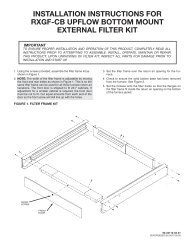
IMPORTANT: TO INSURE PROPER INSTALLATION AND OPERATION OF<br />
THIS PRODUCT, COMPLETELY READ ALL INSTRUCTIONS PRIOR TO<br />
ATTEMPTING TO ASSEMBLE, INSTALL, OPERATE, MAINTAIN OR REPAIR<br />
THIS PRODUCT. UPON UNPACKING OF THE FURNACE, INSPECT ALL<br />
PARTS FOR DAMAGE PRIOR TO INSTALLATION AND START-UP.<br />
5
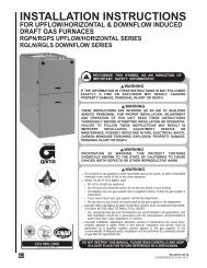
GENERAL INFORMATION<br />
The <strong>RGRA</strong>/<strong>RGRB</strong>/RGTA/<strong>RGRS</strong>/<br />
<strong>RGTS</strong>/RGRT series furnaces are<br />
design-certified by CSA for use with<br />
natural and propane gases as follows:<br />
1. As non-direct vent central forced<br />
air furnaces taking combustion<br />
air from the installation area or<br />
using air ducted from the outside.<br />
2. As direct vent central forced air<br />
furnaces with all combustion air<br />
supplied directly to the furnace<br />
burners through a special air<br />
intake system outlined in these<br />
instructions.<br />
Install this furnace in accordance with<br />
the American National Standard<br />
Z223.1 – latest edition entitled<br />
“National Fuel Gas Code” (NFPA54)<br />
and requirements or codes of the<br />
local utilities or other authorities<br />
having jurisdiction. This is available<br />
from the following:<br />
National Fire Protection<br />
Association, Inc.<br />
Batterymarch Park<br />
Quincy, MA 02269<br />
CSA-INTERNATIONAL<br />
8501 East Pleasant Valley Road<br />
Cleveland, Ohio 44131-5575<br />
Install units in Canada in accordance<br />
with CSA-B149, local installation<br />
codes and authorities having<br />
jurisdiction. CSA-B149 is available<br />
from:<br />
CSA-INTERNATIONAL<br />
178 Rexdale Blvd.<br />
Toronto, Ontario<br />
Canada M9W, 1R3<br />
NOTE: Models having option code 3<strong>20</strong><br />
added at the end of the model number<br />
designation are shipped factory ready<br />
for a horizontal only installation. The<br />
drain trap for downflow installation is<br />
not included in the parts bag for these<br />
appliances.<br />
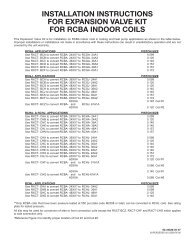
FIGURE 1<br />
UPFLOW FURNACE<br />
FIGURE 2<br />
DOWNFLOW/HORIZONTAL FURNACE<br />
I409<br />
I409<br />
ITEM<br />
ITEM<br />
NO. PART NAME NO. PART NAME<br />
1 CONDENSATE TRAP 13 TOP PLATE<br />
2 DOOR SWITCH 14 BURNER<br />
3 JUNCTION BOX 15 IGNITER (HSI ONLY)<br />
4 TRANSFORMER <strong>16</strong> COMBUSTION AIR INLET<br />
5 BLOCKED DRAIN PRESSURE SWITCH 17 GAS VALVE<br />
6 MAIN PRESSURE SWITCH 18 INDUCED DRAFT BLOWER<br />
7 EXHAUST TRANSITION 19 CAPACITOR<br />
8 CONNECTOR <strong>20</strong> LOW VOLTAGE (THERMOSTAT)<br />
9 OUTLET AIR PIPE TERMINAL<br />
10 SHIPPING PLUG 21 CONTROL MOUNTING PLATE<br />
11 FLAME SENSOR 22 BLOWER<br />
12 OVERTEMPERATURE SWITCH<br />
ITEM<br />
ITEM<br />
NO. PART NAME NO. PART NAME<br />
1 INDUCED DRAFT BLOWER 14 LOW VOLTAGE TERMINAL (THERMOSTAT)<br />
2 CAPACITOR 15 TRANSFORMER<br />
3 INLET AIR CHASE <strong>16</strong> PRESSURE SWITCH<br />
4 DOOR SWITCH 17 OUTLET AIR PIPE<br />
5 JUNCTION BOX 18 GAS VALVE<br />
6 INLET PIPE CONNECTOR 19 CONNECTOR<br />
7 TOP PLATE <strong>20</strong> EXHAUST TRANSITION<br />
8 CONTROL MOUNTING PLATE 21 CONDENSATE TRAP<br />
9 AUXILIARY LIMIT 22 IGNITER (HSI)<br />
10 SHIPPING PLUG 23 MANIFOLD<br />
11 EXHAUST CONNECTION 24 OVERTEMPERATURE SWITCH<br />
12 BLOWER 25 ROLLOUT SWITCH<br />
13 EXHAUST PIPE EXTENSION 26 FLAME SENSOR<br />
27 BURNER<br />
6
IMPORTANT<br />
INFORMATION ABOUT<br />
EFFICIENCY AND INDOOR<br />
AIR QUALITY<br />
Central cooling and heating<br />
equipment is only as efficient as the<br />
duct system that carries the cooled or<br />
heated air. To maintain efficiency,<br />
comfort and good indoor air quality, it<br />
is important to have the proper<br />
balance between the air being<br />
supplied to each room and the air<br />
returning to the cooling and heating<br />
equipment.<br />
Proper balance and sealing of the<br />
duct system improves the efficiency<br />
of the heating and air conditioning<br />
system and improves the indoor air<br />
quality of the home by reducing the<br />
amount of airborne pollutants that<br />
enter homes from spaces where the<br />
ductwork and / or equipment is<br />
located. The manufacturer and the<br />
U.S. Environmental Protection<br />
Agency’s Energy Star Program<br />
recommend that central duct systems<br />
be checked by a qualified contractor<br />
for proper balance and sealing.<br />
! WARNING<br />
DUCT LEAKS CAN CREATE AN<br />
UNBALANCED SYSTEM AND<br />
DRAW POLLUTANTS SUCH AS<br />
DIRT, DUST, FUMES AND ODORS<br />
INTO THE HOME CAUSING<br />
PROPERTY DAMAGE. FUMES<br />
AND ODORS FROM TOXIC,<br />
VOLATILE OR FLAMMABLE<br />
CHEMICALS, AS WELL AS<br />
AUTOMOBILE EXHAUST AND<br />
CARBON MONOXIDE (CO), CAN<br />
BE DRAWN INTO THE LIVING<br />
SPACE THROUGH LEAKING<br />
DUCTS AND UNBALANCED DUCT<br />
SYSTEMS CAUSING PERSONAL<br />
INJURY OR DEATH (SEE FIGURE<br />
3).<br />
• IF AIR-MOVING EQUIPMENT OR<br />
DUCTWORK IS LOCATED IN<br />
GARAGES OR OFF-GARAGE<br />
STORAGE AREAS - ALL JOINTS,<br />
SEAMS, AND OPENINGS IN THE<br />
EQUIPMENT AND DUCT MUST<br />
BE SEALED TO LIMIT THE<br />
MIGRATION OF TOXIC FUMES<br />
AND ODORS INCLUDING<br />
CARBON MONOXIDE FROM<br />
MIGRATING INTO THE LIVING<br />
SPACE.<br />
• IF AIR-MOVING EQUIPMENT OR<br />
DUCTWORK IS LOCATED IN<br />
SPACES CONTAINING FUEL<br />
BURNING APPLIANCES SUCH<br />
AS WATER HEATERS OR<br />
BOILERS - ALL JOINTS, SEAMS,<br />
AND OPENINGS IN THE<br />
EQUIPMENT AND DUCT MUST<br />
ALSO BE SEALED TO PREVENT<br />
DEPRESSURIZATION OF THE<br />
SPACE AND POSSIBLE<br />
MIGRATION OF COMBUSTION<br />
BYPRODUCTS INCLUDING<br />
CARBON MONOXIDE INTO THE<br />
LIVING SPACE.<br />
NOTICE<br />
IMPROPER INSTALLATION, OR<br />
INSTALLATION NOT MADE IN<br />
ACCORDANCE WITH THE CSA<br />
INTERNATIONAL (CSA)<br />
CERTIFICATION OR THESE<br />
INSTRUCTIONS, CAN RESULT IN<br />
UNSATISFACTORY OPERATION<br />
AND/OR DANGEROUS CONDI-<br />
TIONS AND ARE NOT COVERED BY<br />
THE UNIT WARRANTY.<br />
NOTICE<br />
IN COMPLIANCE WITH<br />
RECOGNIZED CODES, IT IS<br />
RECOMMENDED THAT AN<br />
AUXILIARY DRAIN PAN BE<br />
INSTALLED UNDER ALL<br />
EVAPORATOR COILS OR UNITS<br />
CONTAINING EVAPORATOR COILS<br />
OR GAS FURNACES USED WITH<br />
EVAPORATOR COILS THAT ARE<br />
LOCATED IN ANY AREA OF A<br />
STRUCTURE WHERE DAMAGE TO<br />
THE BUILDING OR BUILDING<br />
CONTENTS MAY OCCUR AS A<br />
RESULT OF AN OVERFLOW OF THE<br />
COIL DRAIN PAN OR A STOPPAGE<br />
IN THE PRIMARY CONDENSATE<br />
DRAIN PIPING.<br />
RECEIVING<br />
Immediately upon receipt, all cartons<br />
and contents should be inspected for<br />
transit damage. Units with damaged<br />
cartons should be opened<br />
immediately. If damage is found, it<br />
should be noted on the delivery<br />
papers, and a damage claim filed<br />
with the last carrier.<br />
• After unit has been delivered to job<br />
site, remove carton taking care not<br />
to damage unit.<br />
• Check the unit rating plate for unit<br />
size, electric heat, coil, voltage,<br />
phase, etc. to be sure equipment<br />
matches what is required for the<br />
job specification.<br />
• Read the entire instructions before<br />
starting the installation.<br />
• Some building codes require extra<br />
cabinet insulation and gasketing<br />
when unit is installed in attic<br />
applications.<br />
• If installed in an unconditioned<br />
space, apply caulking around the<br />
power wires, control wires,<br />
refrigerant tubing and condensate<br />
line where they enter the cabinet.<br />
Seal the power wires on the inside<br />
where they exit conduit opening.<br />
Caulking is required to prevent air<br />
leakage into and condensate from<br />
forming inside the unit, control box,<br />
and on electrical controls.<br />
• Install the unit in such a way as to<br />
allow necessary access to the<br />
coil/filter rack and blower/control<br />
compartment.<br />
• Install the unit in a level position to<br />
ensure proper condensate<br />
drainage. Make sure unit is level in<br />
both directions within 1/8”.<br />
• Install the unit in accordance with<br />
any local code which may apply<br />
and the national codes. Latest<br />
editions are available from:<br />
FIGURE 3<br />
MIGRATION OF DANGEROUS SUBSTANCES, FUMES, AND ODORS INTO LIVING SPACES<br />
“National Fire Protection<br />
Association, Inc., Batterymarch<br />
Park, Quincy, MA 02269.” These<br />
publications are:<br />
• ANSI/NFPA No. 70-(Latest Edition)<br />
National Electrical Code.<br />
• NFPA90A Installation of Air<br />
Conditioning and Ventilating<br />
Systems.<br />
• NFPA90B Installation of warm air<br />
heating and air conditioning<br />
systems.<br />
• The equipment has been<br />
evaluated in accordance with the<br />
Code of Federal Regulations,<br />
Chapter XX, Part 3280.<br />
7
LOCATION REQUIREMENTS AND CONSIDERATIONS<br />
GENERAL INFORMATION<br />
!<br />
WARNING<br />
DO NOT USE THIS FURNACE<br />
DURING CONSTRUCTION IF AIR<br />
LADEN CORROSIVE COMPOUNDS<br />
ARE PRESENT SUCH AS<br />
CHLORINE AND FLUORINE.<br />
OTHERWISE, PROVISIONS MUST<br />
BE TAKEN TO PROVIDE CLEAN,<br />
UNCONTAMINATED COMBUSTION<br />
AND VENTILATION AIR TO THE<br />
FURNACE. FURNACE<br />
COMBUSTION AND VENTILATION<br />
AIR CONTAMINATED WITH THESE<br />
COMPOUNDS FORMS ACIDS<br />
DURING COMBUSTION WHICH<br />
CORRODES THE HEAT<br />
EXCHANGER AND COMPONENT<br />
PARTS. SOME OF THESE<br />
CONTAMINANTS ARE FOUND IN,<br />
BUT NOT LIMITED TO, PANELING,<br />
DRY WALL, ADHESIVES, PAINTS,<br />
STAINES, VARNISHES, SEALERS,<br />
AND MASONRY CLEANING<br />
MATERIALS.<br />
! WARNING<br />
DO NOT INSTALL THIS FURNACE<br />
IN A MOBILE HOME!! This furnace<br />
is not approved for installation in a<br />
mobile home. Doing so could cause<br />
FIRE, PROPERTY DAMAGE,<br />
PERSONAL INJURY OR DEATH.<br />
! WARNING<br />
WHEN THIS FURNACE IS<br />
INSTALLED IN A RESIDENTIAL<br />
GARAGE, IT MUST BE INSTALLED<br />
SO THE BURNERS AND IGNITION<br />
SOURCE ARE LOCATED NO LESS<br />
THAN 18 INCHES ABOVE THE<br />
FLOOR. THIS IS TO PREVENT<br />
THE RISK OF IGNITING<br />
FLAMMABLE VAPORS WHICH<br />
MAY BE PRESENT IN A GARAGE.<br />
ALSO, THE FURNACE MUST BE<br />
LOCATED OR PROTECTED TO<br />
AVOID PHYSICAL DAMAGE BY<br />
VEHICLES. FAILURE TO FOLLOW<br />
THESE WARNINGS CAN CAUSE A<br />
FIRE OR EXPLOSION, RESULTING<br />
IN PROPERTY DAMAGE,<br />
PERSONAL INJURY OR DEATH.<br />
1. IMPORTANT: If installing the unit<br />
over a finished ceiling or living<br />
area, be certain to install an<br />
auxiliary condensate drain pan<br />
under the entire unit. This<br />
auxiliary drain pan should extend<br />
under any evaporator coil<br />
installed with the furnace and the<br />
open portion of the condensate<br />
drain assembly. See<br />
“Condensate Drain/Neutralizer”<br />
section for more details.<br />
2. IMPORTANT: If using a cooling<br />
evaporator coil with this furnace:<br />
a. be sure the air passes over<br />
the heat exchanger before<br />
passing over the cooling<br />
coil. The cooled air passing<br />
over the warm ambient air<br />
inside the heat exchanger<br />
tubes can cause<br />
condensation inside the tubes<br />
resulting in corrosion and<br />
eventual failure.<br />
b. install a parallel duct system<br />
to divert all the air from the<br />
furnace allowing it to pass<br />
over the cooling coil only. Use<br />
dampers or other means to<br />
prevent chilled air from<br />
passing over the heat<br />
exchanger.<br />
If these are manual dampers, they<br />
must be equipped to prevent heating<br />
or cooling operation unless the<br />
damper is in the full heat or cool<br />
position.<br />
FIGURE 4<br />
HORIZONTAL FURNACE W/HEAT TAPE ON CONDENSATE TRAP<br />
DRAIN<br />
PIPE<br />
3. IMPORTANT: Install the furnace<br />
level. If it is not level, condensate<br />
cannot drain properly, possibly<br />
causing furnace shut down.<br />
NOTE: These furnaces are approved<br />
for installation in attics, as well as<br />
alcoves, utility rooms, closets and<br />
crawlspaces. Provisions must be<br />
made to prevent freezing of<br />
condensate.<br />
4. ! CAUTION<br />
If this furnace is installed in a<br />
garage, attic and/or any<br />
unconditioned space, install a<br />
self-regulating heat tape<br />
around the condensate trap<br />
and along the entire length of<br />
the condensate drain in the<br />
unconditioned space. See<br />
Figure 4.<br />
When the condensing horizontal<br />
gas furnace is installed in an<br />
unconditioned space where the<br />
temperature would be capable of<br />
reaching close to or below 32°F<br />
(0°C). a self-regulating heat tape<br />
is required on the condensate<br />
drain, along with an insulation<br />
wrap. The heat tape should meet<br />
the following requirements:<br />
a. The heat tape must be UL<br />
listed.<br />
b. The heat tape must be<br />
installed per the<br />
manufacturer’s instructions for<br />
the entire length of drain pipe<br />
in the unconditioned space.<br />
HEAT<br />
TAPE<br />
TRAP<br />
I526<br />
8
c. The heat tape should be rated<br />
at 5 or 6 watts per foot at<br />
1<strong>20</strong>V.<br />
IMPORTANT: Support this unit<br />
when installed. Since this furnace<br />
is suitable for attic or crawl space<br />
installation, it may be installed on<br />
combustible wood flooring or by<br />
using support brackets. See<br />
Figure 5.<br />
5. IMPORTANT: If installing in a<br />
utility room, be sure the door<br />
is wide enough to:<br />
a. allow the largest part of the<br />
furnace to pass; or<br />
b. allow any other appliance<br />
(such as a water heater)<br />
to pass.<br />
6. IMPORTANT: This furnace is not<br />
approved or recommended for<br />
installation on its back, with<br />
access doors facing upwards.<br />
FIGURE 5<br />
HORIZONTAL FURNACE INSTALLED W/SUPPORT BRACKETS<br />
GAS<br />
PIPE<br />
TRAP<br />
INTAKE<br />
VENT<br />
ELECTRICAL<br />
CONDUIT<br />
EXHAUST<br />
FAN<br />
I522<br />
CLEARANCE -<br />
ACCESSIBILITY<br />
The design of forced air furnaces with<br />
input ratings as listed in the tables<br />
under Figures 6, 7, and 8 are certified<br />
by CSA-International for the<br />
clearances to combustible materials<br />
shown in inches.<br />
See name/rating plate and clearance<br />
label for specific model number and<br />
clearance information.<br />
Service clearance of at least 24<br />
inches is recommended in front of<br />
all furnaces.<br />
NOTE: Use recommended 24”<br />
clearance if accessibility clearances<br />
are greater than fire protection<br />
clearances.<br />
! WARNING<br />
UPFLOW AND HORIZONTAL<br />
FURNACES ARE DESIGN-<br />
CERTIFIED FOR INSTALLATION<br />
ON COMBUSTIBLE FLOORS.<br />
NOTE, HOWEVER, THAT<br />
FURNACES MUST NOT BE<br />
INSTALLED DIRECTLY ON<br />
CARPETING, TILE OR OTHER<br />
COMBUSTIBLE MATERIAL OTHER<br />
THAN WOOD FLOORING.<br />
INSTALLATION ON A<br />
COMBUSTIBLE MATERIAL CAN<br />
RESULT IN FIRE, CAUSING<br />
PROPERTY DAMAGE, PERSONAL<br />
INJURY OR DEATH.<br />
SITE SELECTION<br />
1. Select a site in the building near<br />
the center of the proposed, or<br />
existing, duct system.<br />
2. Give consideration to the vent<br />
system piping when selecting the<br />
furnace location. Be sure the<br />
venting system can get from the<br />
furnace to the termination with<br />
minimal length and elbows.<br />
3. Locate the furnace near the<br />
existing gas piping. Or, if running<br />
a new gas line, locate the<br />
furnace to minimize the length<br />
and elbows in the gas piping.<br />
4. Locate the furnace to maintain<br />
proper clearance to combustibles<br />
as shown in the following tables.<br />
! WARNING<br />
DO NOT LIFT THE UNIT BY THE<br />
HEAT EXCHANGER TUBES.<br />
DOING SO CAN CRACK THE HEAT<br />
EXCHANGER ASSEMBLY AND<br />
CAUSE CO2 TO BE RELEASED<br />
INTO THE ENVIRONMENT, WHICH<br />
CAN RESULT IN PERSONAL<br />
INJURY OR DEATH.<br />
! WARNING<br />
COMBUSTIBLE MATERIAL MUST<br />
NOT BE PLACED ON OR AGAINST<br />
THE FURNACE JACKET. THE<br />
AREA AROUND THE FURNACE<br />
MUST BE KEPT CLEAR AND FREE<br />
OF ALL COMBUSTIBLE<br />
MATERIALS INCLUDING<br />
GASOLINE AND OTHER<br />
FLAMMABLE VAPORS AND<br />
LIQUIDS. PLACEMENT OF<br />
COMBUSTIBLE MATERIALS ON,<br />
AGAINST OR AROUND THE<br />
FURNACE JACKET CAN CAUSE<br />
AN EXPLOSION OR FIRE<br />
RESULTING IN PROPERTY<br />
DAMAGE, PERSONAL INJURY OR<br />
DEATH. THE HOMEOWNER<br />
SHOULD BE CAUTIONED THAT<br />
THE FURNACE AREA MUST NOT<br />
BE USED AS A BROOM CLOSET<br />
OR FOR ANY OTHER STORAGE<br />
PURPOSES.<br />
9
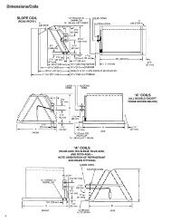
FIGURE 6<br />
CLEARANCE TO COMBUSTIBLES, UPFLOW UNITS<br />
SUPPLY<br />
AIR<br />
26 7 ⁄<strong>16</strong><br />
2 DIA.<br />
GAS CONNECTION<br />
RETURN<br />
AIR<br />
AIRFLOW<br />
27 3 ⁄8<br />
UPFLOW MODELS MINIMUM CLEARANCE (IN.)<br />
MODEL A B C D E F<br />
LEFT RIGHT SHIP<br />
BACK TOP FRONT VENT<br />
SIDE SIDE<br />
WGTS<br />
04 17 1 ⁄2 <strong>16</strong> 11 ⁄32 15 5 ⁄8 2 15 13 25 ⁄32 0 0 0 1 2* 0 111<br />
06 17 1 ⁄2 <strong>16</strong> 11 ⁄32 15 5 ⁄8 2 15 13 25 ⁄32 0 0 0 1 2* 0 117<br />
07 17 1 ⁄2 <strong>16</strong> 11 ⁄32 15 5 ⁄8 2 15 13 25 ⁄32 0 0 0 1 2* 0 124<br />
07 21 19 27 ⁄32 19 3 ⁄<strong>16</strong> 2 18 1 ⁄2 17 3 ⁄8 0 0 0 1 2* 0 137<br />
09 21 19 27 ⁄32 19 1 ⁄8 2 18 1 ⁄2 17 9 ⁄32 0 0 0 1 2* 0 148<br />
10 21 19 27 ⁄32 19 1 ⁄8 2 18 1 ⁄2 17 9 ⁄32 0 0 0 1 2* 0 152<br />
12 24 1 ⁄2 23 11 ⁄32 22 5 ⁄8 2 22 <strong>20</strong> 25 ⁄32 0 0 0 1 2* 0 <strong>16</strong>0<br />
*A service clearance of at least 24 inches is recommended in front of all furnaces.<br />
2 DIA.<br />
GAS CONNECTION<br />
I3<strong>92</strong><br />
10
FIGURE 7<br />
CLEARANCE TO COMBUSTIBLES, DOWNFLOW UNITS<br />
RETURN<br />
AIR<br />
SUPPLY<br />
AIR<br />
DOWNFLOW MODELS MINIMUM CLEARANCE (IN.)<br />
MODEL A B C D E F<br />
LEFT RIGHT SHIP<br />
BACK TOP FRONT VENT<br />
SIDE SIDE<br />
WGTS<br />
04 17 1 ⁄2 <strong>16</strong> 11 ⁄32 15 5 ⁄8 2 <strong>16</strong> 5 ⁄8 13 7 ⁄8 0 0 0 1 2* 0 111<br />
06 17 1 ⁄2 <strong>16</strong> 11 ⁄32 15 5 ⁄8 2 <strong>16</strong> 5 ⁄8 13 7 ⁄8 0 0 0 1 2* 0 117<br />
07 17 1 ⁄2 <strong>16</strong> 11 ⁄32 15 5 ⁄8 2 <strong>16</strong> 5 ⁄8 13 7 ⁄8 0 0 0 1 2* 0 124<br />
07 21 19 27 ⁄32 19 3 ⁄<strong>16</strong> 2 <strong>20</strong> 1 ⁄8 17 3 ⁄8 0 0 0 1 2* 0 137<br />
09 21 19 11 ⁄32 19 3 ⁄<strong>16</strong> 2 <strong>20</strong> 1 ⁄8 17 3 ⁄8 0 0 0 1 2* 0 148<br />
10 21 19 11 ⁄32 19 3 ⁄<strong>16</strong> 2 <strong>20</strong> 1 ⁄8 17 3 ⁄8 0 0 0 1 2* 0 152<br />
12 24 1 ⁄2 23 11 ⁄32 22 5 ⁄8 2 23 5 ⁄8 <strong>20</strong> 7 ⁄8 0 0 0 1 2* 0 <strong>16</strong>0<br />
*A service clearance of at least 24 inches is recommended in front of all furnaces.<br />
AIRFLOW<br />
25 13 ⁄<strong>16</strong><br />
2 DIA.<br />
GAS CONNECTION<br />
2 DIA.<br />
ALT. GAS<br />
CONNECTION<br />
4 3 ⁄8<br />
NOTE: IN DOWNFLOW CONFIGURATION, OPTIONAL AIR CUTOUT IS NOT PERMITTED.<br />
I393<br />
11
FIGURE 8<br />
CLEARANCE TO COMBUSTIBLES, HORIZONTAL UNITS<br />
DOWNFLOW MODELS MINIMUM CLEARANCE (IN.)<br />
LEFT RIGHT SHIP<br />
BACK TOP FRONT VENT<br />
SIDE SIDE<br />
WGTS<br />
4 3 ⁄8<br />
MODEL A B C D E F<br />
2 DIA.<br />
GAS<br />
CONNECTION<br />
2 DIA.<br />
ALT. GAS<br />
CONNECTION<br />
04 17 1 ⁄2 <strong>16</strong> 11 ⁄32 15 5 ⁄8 2 <strong>16</strong> 5 ⁄8 13 7 ⁄8 0 0 0 1 2* 0 111<br />
06 17 1 ⁄2 <strong>16</strong> 11 ⁄32 15 5 ⁄8 2 <strong>16</strong> 5 ⁄8 13 7 ⁄8 0 0 0 1 2* 0 117<br />
07 17 1 ⁄2 <strong>16</strong> 11 ⁄32 15 5 ⁄8 2 <strong>16</strong> 5 ⁄8 13 7 ⁄8 0 0 0 1 2* 0 124<br />
07 21 19 27 ⁄32 19 3 ⁄<strong>16</strong> 2 <strong>20</strong> 1 ⁄8 17 3 ⁄8 0 0 0 1 2* 0 137<br />
09 21 19 27 ⁄32 19 3 ⁄<strong>16</strong> 2 <strong>20</strong> 1 ⁄8 17 3 ⁄8 0 0 0 1 2* 0 148<br />
10 21 19 27 ⁄32 19 3 ⁄<strong>16</strong> 2 <strong>20</strong> 1 ⁄8 17 3 ⁄8 0 0 0 1 2* 0 152<br />
12 24 1 ⁄2 23 11 ⁄32 22 5 ⁄8 2 23 5 ⁄8 <strong>20</strong> 5 ⁄8 0 0 0 1 2* 0 <strong>16</strong>0<br />
*A service clearance of at least 24 inches is recommended in front of all furnaces.<br />
IMPORTANT: This furnace is not approved or recommended for<br />
installation on its back, with access doors facing upwards.<br />
25 13 ⁄<strong>16</strong><br />
I5<strong>20</strong><br />
12
DUCTING<br />
Proper air flow is required for the<br />
correct operation of this furnace.<br />
Too little air flow can cause erratic<br />
operation and can damage the heat<br />
exchanger. The duct system must<br />
carry the correct amount of air for<br />
heating and cooling if summer air<br />
conditioning is used.<br />
Size the ducts according to<br />
acceptable industry standards and<br />
methods. The total static pressure<br />
drop of the air distribution system<br />
should not exceed 0.5" w.c.<br />
NOTE: Return air grilles and warm air<br />
registers must not be obstructed<br />
! WARNING<br />
NEVER ALLOW THE PRODUCTS<br />
OF COMBUSTION FROM THE<br />
FLUE TO ENTER THE RETURN AIR<br />
DUCTWORK OR THE CIRCULATED<br />
AIR SUPPLY. ALL RETURN<br />
DUCTWORK MUST BE<br />
ADEQUATELY SEALED AND<br />
SECURED TO THE FURNACE<br />
WITH SHEET METAL SCREWS;<br />
AND JOINTS, TAPED. ALL OTHER<br />
DUCT JOINTS MUST BE SECURED<br />
WITH APPROVED CONNECTIONS<br />
AND SEALED AIRTIGHT. WHEN<br />
AN UPFLOW FURNACE IS<br />
MOUNTED ON A PLATFORM WITH<br />
RETURN THROUGH THE BOTTOM,<br />
IT MUST BE SEALED AIRTIGHT<br />
BETWEEN THE FURNACE AND<br />
THE RETURN AIR PLENUM. THE<br />
FLOOR OR PLATFORM MUST<br />
PROVIDE SOUND PHYSICAL<br />
SUPPORT OF THE FURNACE<br />
WITHOUT SAGGING, CRACKS, OR<br />
GAPS, AROUND THE BASE,<br />
PROVIDING A SEAL BETWEEN<br />
THE SUPPORT AND THE BASE.<br />
FAILURE TO PREVENT<br />
PRODUCTS OF COMBUSTION<br />
FROM BEING CIRCULATED INTO<br />
THE LIVING SPACE CAN CREATE<br />
POTENTIALLY HAZARDOUS<br />
CONDITIONS, INCLUDING<br />
CARBON MONOXIDE POISONING<br />
THAT COULD RESULT IN<br />
PERSONAL INJURY OR DEATH.<br />
DO NOT, UNDER ANY<br />
CIRCUMSTANCES, CONNECT<br />
RETURN OR SUPPLY DUCTWORK<br />
TO OR FROM ANY OTHER HEAT<br />
PRODUCING DEVICE SUCH AS A<br />
FIREPLACE INSERT, STOVE, ETC.<br />
DOING SO MAY RESULT IN FIRE,<br />
CARBON MONOXIDE POISONING,<br />
EXPLOSION, PERSONAL INJURY<br />
OR PROPERTY DAMAGE.<br />
IMPORTANT: Some high efficiency<br />
filters have a greater than normal<br />
resistance to air flow. This can<br />
adversely affect furnace operation.<br />
BE SURE TO CHECK AIR FLOW.<br />
IMPORTANT: When using outside<br />
air, design and adjust the system to<br />
maintain a return air temperature<br />
ABOVE 50° F during the heating<br />
season.<br />
UPFLOW UNITS<br />
1. Position the unit to minimize long<br />
runs of duct or runs of duct with<br />
many turns and elbows.<br />
2. Open the return air compartment.<br />
! WARNING<br />
UPFLOW FURNACE: A SOLID<br />
METAL BASE PLATE MUST BE<br />
INSTALLED IN THE FURNACE<br />
BOTTOM WHEN USING SIDE<br />
RETURN. FAILURE TO INSTALL A<br />
BASE PLATE COULD CAUSE THE<br />
PRODUCTS OF COMBUSTION TO<br />
CIRCULATE INTO THE LIVING<br />
SPACE AND CREATE POTENTIAL -<br />
LY HAZARDOUS CONDITIONS,<br />
INCLUDING CARBON MONOXIDE<br />
POISONING OR DEATH.<br />
a. Cut an opening in the side.<br />
The opening should<br />
be cut the full width of the<br />
knockouts on the unit. See<br />
Figure 9.<br />
NOTE: Where the maximum air flow<br />
is 1800 CFM or more, both sides or<br />
the bottom must be used for return<br />
air.<br />
3. Connect the return duct or return<br />
air cabinet to the unit. Make the<br />
connection air tight to prevent<br />
entraining combustion gases<br />
from an adjacent fuel-burning<br />
appliance.<br />
4. Be sure to have adequate<br />
space for the unit filter.<br />
NOTE: DO NOT take return air<br />
from bathrooms, kitchens,<br />
furnace rooms, garages, utility or<br />
laundry rooms, or cold areas.<br />
NOTE: DO NOT use a rear air<br />
return.<br />
FIGURE 9<br />
CUTOUT AND DRILL INFORMATION<br />
JACKET<br />
5. If summer air conditioning is<br />
desired, position the indoor coil<br />
on the top of the unit. Insure that<br />
no air can bypass this coil.<br />
6. Connect the supply air plenum to<br />
the furnace plenum opening.<br />
IMPORTANT: If a flexible duct<br />
connector must be used, it<br />
MUST be rated for a minimum<br />
temperature of 250°F.<br />
continuous.<br />
DOWNFLOW UNITS<br />
1. Position the unit to minimize long<br />
runs of duct or runs of duct with<br />
many turns and elbows.<br />
2. If summer air conditioning is<br />
desired, position the indoor coil<br />
on the bottom of the unit. Insure<br />
that no air can bypass this coil.<br />
3. If installing on a combustible floor<br />
and not using an air<br />
conditioning plenum, install the<br />
special non-combustible floor<br />
base. See Figure 10.<br />
! WARNING<br />
THE DOWNFLOW FURNACE<br />
DESIGN IS CERTIFIED FOR<br />
INSTALLATION ON A NON-<br />
COMBUSTIBLE FLOOR. USE THE<br />
SPECIAL BASE SPECIFIED ON<br />
THE FURNACE CLEARANCE<br />
LABEL. FAILURE TO INSTALL THE<br />
SPECIAL BASE MAY RESULT IN<br />
FIRE, PROPERTY DAMAGE,<br />
PERSONAL INJURY OR DEATH.<br />
THIS SPECIAL BASE IS SHIPPED<br />
FROM THE FACTORY AS AN<br />
ACCESSORY.<br />
8.000<br />
DRILL (2)<br />
3/<strong>16</strong>" DIA.<br />
HOLES<br />
4.875<br />
1.531<br />
13
4. Connect the furnace to the<br />
supply air plenum.<br />
5. Connect the return air ducting to<br />
the return air opening at the top<br />
of the unit. Make the connection<br />
air tight to prevent entraining<br />
combustion gases from an<br />
adjacent fuel-burning appliance.<br />
6. Be sure to have adequate<br />
space for the unit filter.<br />
NOTE: DO NOT take return air<br />
from bathrooms, kitchens,<br />
furnace rooms, garages, utility or<br />
laundry rooms, or cold areas.<br />
HORIZONTAL UNIT<br />
IMPORTANT: This furnace may only<br />
be installed so that when facing the<br />
front of the furnace, supply air is<br />
discharged on the left hand side.<br />
1. Position the unit to minimize long<br />
runs or runs with many turns and<br />
elbows.<br />
2. If summer air conditioning is<br />
desired, position the indoor coil<br />
on the left end of the unit. Insure<br />
that no air can bypass this coil.<br />
3. Connect the furnace to the<br />
supply air plenum.<br />
4. Connect the return air ducting to<br />
the return air opening at the right<br />
end of the unit. Make the<br />
connection air tight to prevent<br />
pulling combustion gases from<br />
an adjacent fuel-burning<br />
appliance.<br />
FIGURE 10<br />
COMBUSTIBLE FLOOR BASE<br />
5. Be sure to have adequate<br />
space for the unit filter.<br />
NOTE: DO NOT take return air<br />
from bathrooms, kitchens,<br />
furnace rooms, garages, utility or<br />
laundry rooms, or cold areas.<br />
VENTING AND COMBUSTION AIR PIPING*<br />
14<br />
GENERAL INFORMATION<br />
! WARNING<br />
READ AND FOLLOW ALL<br />
INSTRUCTIONS IN THIS SECTION.<br />
FAILURE TO PROPERLY VENT<br />
THIS FURNACE CAN CAUSE<br />
CARBON MONOXIDE POISONING<br />
OR AN EXPLOSION OR FIRE,<br />
RESULTING IN PROPERTY<br />
DAMAGE, PERSONAL INJURY<br />
OR DEATH.<br />
This furnace removes both sensible<br />
and latent heat from the combustion<br />
flue gases. Removal of latent heat<br />
results in condensation of flue gas<br />
water vapor. This condensed water<br />
vapor drains from the secondary heat<br />
exchanger and out of the unit into a<br />
drain trap.<br />
When installed as a non-direct vent<br />
furnace, only exhaust piping is<br />
required and inside combustion air<br />
may be used. Refer to section on<br />
“COMBUSTION & VENTILATION AIR<br />
FOR FURNACE INSTALLATIONS.”<br />
Direct vent installations require a<br />
dedicated combustion air and venting<br />
system. All air for combustion is taken<br />
from the outside atmosphere and all<br />
combustion products are discharged<br />
to the outdoors.<br />
! WARNING<br />
IN CANADA, PRODUCTS<br />
CERTIFIED FOR INSTALLATION<br />
AND INTENDED TO BE VENTED<br />
WITH PLASTIC VENT SYSTEMS<br />
(PVC, CPVC) MUST USE VENT<br />
SYSTEMS THAT ARE CERTIFIED<br />
AND STAMPED TO THE STANDARD<br />
FOR TYPE BH GAS VENTING<br />
SYSTEMS, ULC S636.<br />
THE COMPONENTS OF THE<br />
CERTIFIED MATERIAL MUST NOT<br />
BE INTERCHANGED WITH OTHER<br />
VENT SYSTEMS OR UNLISTED<br />
PIPE/FITTINGS.<br />
PLASTIC COMPONENTS AND<br />
SPECIFIED PRIMERS AND GLUES<br />
OF THE CERTIFIED SYSTEM MUST<br />
BE FROM A SINGLE SYSTEM<br />
MANUFACTURER AND NOT<br />
U.S. PIPE & FITTING MATERIAL*<br />
Schedule 40 PVC (Pipe)<br />
Schedule 40 PVC (Cellular Core Pipe)<br />
Schedule 40 PVC (Fittings)<br />
SDR-21PVC (Pipe)<br />
SDR-26 PVC (Pipe)<br />
Schedule 40 ABS Cellular Core DWV (Pipe)<br />
Schedule 40 ABS (Pipe)<br />
Schedule 40 ABS (Fittings)<br />
ABS-DWV (Drain Waste & Vent)<br />
(Pipe & Fittings)<br />
PVC-DWV (Drain Waste & Vent)<br />
(Pipe & Fittings)<br />
*Starting in <strong>20</strong>07, Canada allows ULC-S636 PVC or CPVC only.<br />
INTERMIXED WITH OTHER<br />
SYSTEM MANUFACTURER’S<br />
PARTS.<br />
NOTE: INLET AIR PIPING IS NOT<br />
CONSIDERED TO BE A PART OF<br />
THE “VENTING SYSTEM”. THE<br />
REQUIREMENT THAT VENT<br />
MATERIAL BE CERTIFIED TO ULC<br />
S636 DOES NOT APPLY TO INLET<br />
AIR PIPING.<br />
The combustion air and vent pipe<br />
fittings must conform to American<br />
National Standards Institute (ANSI)<br />
and American Society for Testing<br />
Materials (ASTM) standards as<br />
shown below:<br />
ASTM<br />
SPECIFICATION<br />
D1785<br />
F891<br />
D2466<br />
D2241<br />
D2241<br />
F628<br />
D1527<br />
D2468<br />
D2661<br />
D2665
OVERTEMPERATURE<br />
SAFETY SWITCHES<br />
Furnaces are equipped with safety<br />
switches in the control compartment<br />
to protect against overtemperature<br />
conditions caused by inadequate<br />
combustion air supply. The switches<br />
for the upflow and downflow models<br />
are located in the burner<br />
compartment. If a switch is tripped it<br />
must be manually reset.<br />
! WARNING<br />
DO NOT JUMPER THESE<br />
DEVICES! IF ONE OF THESE<br />
SWITCHES SHOULD TRIP, A<br />
QUALIFIED INSTALLER, SERVICE<br />
AGENCY OR THE GAS SUPPLIER<br />
MUST BE CALLED TO CHECK<br />
AND/OR CORRECT FOR<br />
ADEQUATE COMBUSTION AIR<br />
SUPPLY. DO NOT RESET THE<br />
SWITCHES WITHOUT TAKING<br />
CORRECTIVE ACTION TO ASSURE<br />
THAT AN ADEQUATE SUPPLY OF<br />
COMBUSTION AIR IS MAINTAINED<br />
UNDER ALL CONDITIONS OF<br />
OPERATION. FAILURE TO DO SO<br />
CAN RESULT IN CARBON<br />
MONOXIDE POISONING OR<br />
DEATH. IF THIS UNIT IS MOUNTED<br />
IN A CLOSET, THE DOOR MUST<br />
BE CLOSED WHEN MAKING THIS<br />
CHECK.<br />
REPLACE THESE SWITCHES<br />
ONLY WITH THE IDENTICAL<br />
REPLACEMENT PART.<br />
EXISTING VENT SYSTEMS*<br />
*In Canada see ULC-S636 requirements.<br />
When the installation of this furnace<br />
replaces an existing furnace that is<br />
removed from a vent system serving<br />
other appliances, the vent system is<br />
likely to be too large to properly vent<br />
the remaining attached appliances.<br />
The following steps should be<br />
followed with each appliance<br />
remaining connected to the original<br />
common vent system. Place the<br />
appliance to be tested in operation,<br />
while the other appliances remaining<br />
connected to the common vent<br />
system are not in operation. Test the<br />
operation of each appliance<br />
individually by the following method.<br />
1. Permanently seal any unused<br />
openings in the common venting<br />
system.<br />
2. Visually inspect the venting<br />
system for proper size and<br />
horizontal pitch and determine<br />
that there is no blockage,<br />
restriction, leakage, corrosion or<br />
other deficiencies which could<br />
cause an unsafe condition.<br />
3. If practical, close all building<br />
doors, windows and all doors<br />
between the space where the<br />
appliances remaining connected<br />
to the common venting system<br />
are located.<br />
Turn on clothes dryers and any<br />
appliance not connected to the<br />
common venting system. Turn on<br />
any exhaust fans, such as range<br />
hoods and bathroom exhausts,<br />
so they will operate at maximum<br />
speed. Do not operate a summer<br />
exhaust fan. Close fireplace<br />
dampers.<br />
4. Follow the lighting instructions.<br />
Place the appliance being<br />
inspected into operation. Adjust<br />
the thermostat so the appliance<br />
will operate continuously.<br />
5. Test for spillage at the draft hood<br />
relief opening after 5 minutes of<br />
main burner operation. Use the<br />
flame of a match or candle, or<br />
smoke from a cigarette, cigar<br />
or pipe.<br />
6. After it has been determined that<br />
each appliance that remains<br />
connected to the common<br />
venting system properly vents<br />
(when tested as outlined above),<br />
return doors, windows, exhaust<br />
fans, fireplace dampers and any<br />
other gas-burning appliance to<br />
their previous conditions of use.<br />
7. If improper venting is observed<br />
during any of the above tests, the<br />
common venting system must be<br />
resized. See vent tables in these<br />
instructions<br />
When the furnace is installed in the<br />
same space with other gas appliances<br />
such as a water heater, be sure there<br />
is an adequate supply of combustion<br />
and ventilation air for the other<br />
appliances. Do not delete or reduce<br />
the combustion air supply required by<br />
the other gas appliances in this space.<br />
See Z223.1, National Fuel Gas Code<br />
(NFPA54) for determining the<br />
combustion air requirements for gas<br />
appliances. An unconfined space must<br />
have at least 50 cubic feet (volume) for<br />
each 1,000 BTUH of the total input of<br />
all appliances in the space. If the open<br />
space containing the appliances is in a<br />
building with tight construction<br />
(contemporary construction), outside<br />
air may still be required for the<br />
appliances to burn and vent properly.<br />
Outside air openings should be sized<br />
the same as for a confined space.<br />
JOINING PIPE AND FITTINGS<br />
! WARNING<br />
PVC SOLVENT CEMENTS AND<br />
PRIMERS ARE HIGHLY<br />
FLAMMABLE. PROVIDE<br />
ADEQUATE VENTILATION AND DO<br />
NOT ASSEMBLE NEAR HEAT<br />
SOURCE OR AN OPEN FLAME. DO<br />
NOT SMOKE. AVOID SKIN OR EYE<br />
CONTACT. OBSERVE ALL<br />
CAUTIONS AND WARNINGS<br />
PRINTED ON MATERIAL<br />
CONTAINERS. FAILURE TO<br />
FOLLOW THESE GUIDELINES MAY<br />
RESULT IN FIRE, EXPLOSION OR<br />
ASPHYXIATION CAUSING<br />
PERSONAL INJURY OR DEATH.<br />
All pipe, fittings, solvent cement,<br />
primers and procedures must conform<br />
to American National Standard<br />
Institute and American Society for<br />
Testing and Materials (ANSI/ASTM)<br />
standards in the U.S.<br />
Pipe and Fittings - ASTM-D1785,<br />
D2466, D2665, D2231, D2661 and<br />
F628.<br />
PVC Primer and Solvent Cement -<br />
ASTM-D2564<br />
ABS Pipe and Fittings - Use ABS<br />
Primer and Solvent Cement D2235<br />
Procedure for Cementing Joints -<br />
ASTM-D2855<br />
IMPORTANT: The plastic combustion<br />
air and venting components are of<br />
PVC. If using ABS piping, ensure that<br />
the solvent cement is compatible for<br />
joining PVC to ABS components or<br />
use a mechanical connection that can<br />
withstand the vent temperatures and<br />
are corrosion resistant.<br />
CEMENTING JOINTS<br />
Properly seal all joints in the PVC<br />
vent using the following materials and<br />
procedures.<br />
PVC CLEANER-PRIMER AND<br />
PVC MEDIUM-BODY SOLVENT<br />
CEMENT<br />
IMPORTANT: After cutting pipe,<br />
remove all ragged edges and burrs.<br />
This is important to prevent reduction<br />
in pressure drop throughout the<br />
system.<br />
1. Cut pipe end square. Chamfer<br />
edge of pipe. Clean fitting socket<br />
and pipe joint area of all dirt,<br />
grease and moisture.<br />
2. After checking pipe and socket<br />
for proper fit, wipe socket and<br />
pipe with cleaner-primer. Apply<br />
a liberal coat of primer to inside<br />
surface of socket and outside of<br />
pipe. Read instructions included<br />
with the primer for proper<br />
application.<br />
3. Apply a thin coat of cement<br />
evenly in the socket. Quickly<br />
apply a heavy coat of cement to<br />
the pipe end and insert pipe into<br />
fitting with a slight twisting<br />
movement until it bottoms out.<br />
NOTE: Cement must be fluid; if<br />
not, recoat.<br />
4. Hold the pipe in the fitting for 30<br />
seconds to prevent the tapered<br />
socket from pushing the pipe out<br />
of the fitting.<br />
5. Wipe all excess cement from the<br />
joint with a rag. Allow 15 minutes<br />
before handling. Cure time varies<br />
according to fit, temperature and<br />
humidity.<br />
NOTE: Stir the solvent cement<br />
frequently while using. Use a natural<br />
bristle brush or the dauber supplied<br />
with the can. The proper brush size is<br />
one inch.<br />
IMPORTANT: For Proper Installation<br />
DO NOT use solvent cement that<br />
has become curdled, lumpy or<br />
thickened.<br />
DO NOT thin. Observe shelf<br />
precautions printed on containers.<br />
For application below 32°F, use only<br />
low-temperature-type solvent<br />
cement.<br />
15
COMBUSTION AND VENTILATION AIR<br />
NON-DIRECT<br />
FURNACE INSTALLATIONS<br />
! WARNING<br />
THE FURNACE AND ANY OTHER<br />
FUEL-BURNING APPLIANCE MUST<br />
BE PROVIDED WITH ENOUGH<br />
FRESH AIR FOR PROPER<br />
COMBUSTION AND VENTILATION<br />
OF THE FLUE GASES. MOST<br />
HOMES WILL REQUIRE THAT<br />
OUTSIDE AIR BE SUPPLIED INTO<br />
THE FURNACE AREA. FAILURE<br />
TO DO SO CAN CAUSE<br />
PERSONAL INJURY OR DEATH<br />
FROM CARBON MONOXIDE<br />
POISONING.<br />
Adequate facilities for providing air for<br />
combustion and ventilation must be<br />
provided in accordance with section<br />
5.3, “Air for Combustion and<br />
Ventilation” of the National Fuel Gas<br />
Code, ANSI Z223.1 (latest edition) or<br />
applicable provisions for the local<br />
building codes, and not obstructed so<br />
as to prevent the flow of air to the<br />
furnace.<br />
IMPORTANT: Air for combustion and<br />
ventilation must not come from a<br />
corrosive atmosphere. Any failure<br />
due to corrosive elements in the<br />
atmosphere is excluded from<br />
warranty coverage.<br />
The following types of installation<br />
(but not limited to the following) will<br />
require OUTDOOR AIR for<br />
combustion, due to chemical<br />
exposures:<br />
• Commercial buildings<br />
• Buildings with indoor pools<br />
• Furnaces installed in laundry rooms<br />
• Furnaces in hobby or craft rooms<br />
• Furnaces installed near chemical<br />
storage areas.<br />
Exposure to the following substances<br />
in the combustion air supply (but not<br />
limited to the following) will also<br />
require OUTDOOR AIR for<br />
combustion:<br />
• Permanent wave solutions<br />
• Chlorinated waxes and cleaners<br />
• Chlorine-based swimming pool<br />
chemicals<br />
• Water softening chemicals<br />
• De-icing salts or chemicals<br />
• Carbon tetrachloride<br />
• Halogen type refrigerants<br />
• Cleaning solvents (such as<br />
perchloroethylene)<br />
• Printing inks, paint removers,<br />
varnishes, etc.<br />
• Hydrochloric acid<br />
• Cements and glues<br />
• Antistatic fabric softeners for<br />
clothes dryers<br />
• Masonry curing and acid washing<br />
materials<br />
Combustion air must be free of acidforming<br />
chemicals such as sulphur,<br />
fluorine and chlorine. These elements<br />
are found in aerosol sprays,<br />
detergents, bleaches, cleaning<br />
solvents, air fresheners, paint and<br />
varnish removers, refrigerants and<br />
many other commercial and<br />
household products. When burned in<br />
a gas flame, vapors from these<br />
products form acid compounds. The<br />
acid compounds increase the dew<br />
point temperature of the flue products<br />
and are highly corrosive after they<br />
condense.<br />
! WARNING<br />
ALL FURNACE INSTALLATIONS<br />
MUST COMPLY WITH THE<br />
NATIONAL FUEL GAS CODE AND<br />
LOCAL CODES TO PROVIDE<br />
ADEQUATE COMBUSTION AND<br />
VENTILATION AIR FOR THE<br />
FURNACE. FAILURE TO DO SO<br />
CAN RESULT IN EXPLOSION,<br />
FIRE, PROPERTY DAMAGE,<br />
CARBON MONOXIDE POISONING,<br />
PERSONAL INJURY OR DEATH.<br />
Combustion air requirements are<br />
determined by whether the furnace is<br />
in an open (unconfined) area or in a<br />
confined space such as a closet or<br />
small room.<br />
EXAMPLE 1:<br />
FURNACE LOCATED IN AN<br />
UNCONFINED SPACE<br />
Using indoor air for combustion.<br />
An unconfined space must have at<br />
least 50 cubic feet for each 1,000<br />
BTUH of the total input for all<br />
appliances in the space. Here are a<br />
few examples of the room sizes<br />
required for different inputs. The sizes<br />
are based on 8-foot ceilings.<br />
BTUH Minimum Sq. Feet Typical Room Size<br />
Input With 8' Ceiling With 8' Ceiling<br />
45,000 281 14' x <strong>20</strong>' OR <strong>16</strong>' x 18'<br />
60,000 375 15' x 25' OR 19' x <strong>20</strong>'<br />
75,000 469 15' x 31' OR <strong>20</strong>' x 24'<br />
90,000 563 <strong>20</strong>’ x 28’ OR 24’ x 24’<br />
105,000 657 <strong>20</strong>' x 33' OR 26' x 25'<br />
1<strong>20</strong>,000 750 25' x 30' OR 24' x 32'<br />
If the open space containing the<br />
furnace is in a building with tight<br />
construction, outside air may still be<br />
required for the furnace to operate<br />
and vent properly. Outside air<br />
openings should be sized the same<br />
as for a confined space.<br />
EXAMPLE 2:<br />
FURNACE LOCATED IN A<br />
CONFINED SPACE<br />
A confined space (any space smaller<br />
than shown above as “unconfined”)<br />
must have openings into the space<br />
which are located in accordance with<br />
the requirements set forth in the<br />
following subsections A and B. Size<br />
the openings by how they are<br />
connected to the heated area or to<br />
the outside,<br />
and by the input of all appliances in<br />
the space.<br />
If confined space is within a building<br />
with tight construction, combustion air<br />
must be taken from outdoors or area<br />
freely communicating with the<br />
outdoors.<br />
A. USING INDOOR AIR FOR<br />
COMBUSTION<br />
IMPORTANT: Air should not be<br />
taken from a heated space with a<br />
fireplace, exhaust fan or other<br />
device that may produce a<br />
negative pressure.<br />
If combustion air is taken from the<br />
heated area, the openings must<br />
each have at least 100 square<br />
inches of free area. Each opening<br />
must have at least one square inch<br />
of free area for each 1,000 BTUH<br />
of total input in the space. Here<br />
are some examples of typical<br />
openings required.<br />
<strong>16</strong>
BTUH<br />
Input<br />
Free Area<br />
Each Opening<br />
45,000 100 square inches<br />
60,000 100 square inches<br />
75,000 100 square inches<br />
90,000 100 square inches<br />
105,000 105 square inches<br />
1<strong>20</strong>,000 1<strong>20</strong> square inches<br />
B. USING OUTDOOR AIR FOR<br />
COMBUSTION<br />
IMPORTANT: Do not take air from<br />
an attic space that is equipped<br />
with power ventilation.<br />
The confined space must<br />
communicate with the outdoors in<br />
accordance with Methods 1 or 2.<br />
The minimum dimension of air<br />
openings shall not be less than 3<br />
inches. Where ducts are used,<br />
they shall be of the same crosssectional<br />
area as the free area of<br />
the openings to which they<br />
connect.<br />
Method 1<br />
Two permanent openings, one<br />
located within 12 inches of the top<br />
and one located within 12 inches<br />
of the bottom of the enclosure,<br />
shall be provided. The openings<br />
shall communicate directly, or by<br />
ducts, with the outdoors or spaces<br />
(crawl or attic) that freely<br />
communicate with the outdoors.<br />
a. Where directly communicating<br />
with the outdoors or where<br />
communicating to the outdoors<br />
FIGURE 11<br />
AIR FROM HEATED SPACE<br />
GAS<br />
WATER<br />
HEATER<br />
through vertical ducts as shown in<br />
Figure 12, each opening shall<br />
have a minimum free area of 1<br />
square inch for each 4,000 BTUH<br />
of total appliance input rating in the<br />
enclosure.<br />
BTUH Free Area Round Pipe<br />
Input Each Opening Size<br />
45,000 11.25 square inches 4"<br />
60,000 15.00 square inches 5"<br />
75,000 18.75 square inches 5"<br />
90,000 22.50 square inches 6"<br />
105,000 26.25 square inches 6"<br />
1<strong>20</strong>,000 30.00 square inches 6"<br />
FURNACE<br />
NOTE:<br />
EACH OPENING SHALL<br />
HAVE A FREE AREA OF<br />
NOT LESS THAN ONE<br />
SQUARE INCH PER 1,000<br />
BTU PER H0UR OF THE<br />
TOTAL INPUT RATING OF<br />
ALL EQUIPMENT IN THE<br />
ENCLOSURE, BUT NOT<br />
LESS THAN 100 SQUARE<br />
INCHES.<br />
b. Where communicating with<br />
outdoors through horizontal ducts,<br />
each opening shall have a<br />
minimum free area of 1 square<br />
inch for each 2,000 BTUH of total<br />
input rating of all equipment in the<br />
enclosure (Seee Figure 13).<br />
Here are some typical sizes:<br />
BTUH Free Area Round Pipe<br />
Input Each Opening Size<br />
45,000 22.50 square inches 6"<br />
60,000 30.00 square inches 6"<br />
75,000 37.50 square inches 7"<br />
90,000 45.00 square inches 8"<br />
105,000 52.50 square inches 8"<br />
1<strong>20</strong>,000 60.00 square inches 9"<br />
FIGURE 12<br />
AIR FROM ATTIC/CRAWL SPACE<br />
FIGURE 13<br />
OUTSIDE AIR USING A HORIZONTAL DUCT<br />
OUTLET AIR<br />
IN ATTIC<br />
MUST BE<br />
ABOVE<br />
INSULATION<br />
GABLE<br />
VENT<br />
VENTILATED<br />
ATTIC GABLE OR<br />
SOFFIT VENTS<br />
1 SQ. INCH PER<br />
4000 BTUH<br />
OUTLET AIR<br />
GAS<br />
WATER<br />
HEATER<br />
FURNACE<br />
OPTIONAL 1 SQ. INCH PER 4000 BTUH INLET AIR<br />
12" MAX.<br />
GAS<br />
WATER<br />
HEATER<br />
FURNACE<br />
12"<br />
MAX.<br />
OUTLET AIR 1 SQ. INCH<br />
PER <strong>20</strong>00 BTUH<br />
INLET AIR 1 SQ. INCH<br />
PER <strong>20</strong>00 BTUH<br />
1 SQ. INCH PER<br />
4000 BTUH INLET AIR<br />
17
Method 2<br />
(Not Shown)<br />
One permanent opening, located<br />
within 12 inches of the top of the<br />
enclosure, shall be permitted<br />
where the equipment has<br />
clearances of at least 1 inch from<br />
the sides and back and 6 inches<br />
from the front of the appliance.<br />
The opening shall directly<br />
communicate with the outdoors or<br />
communicate through a vertical or<br />
horizontal duct to the outdoors or<br />
spaces (crawl or attic) that freely<br />
communicate with the outdoors,<br />
and shall have a minimum free<br />
area of:<br />
a. 1 square inch for each 3,000<br />
BTUH of the total input rating of all<br />
equipment located in the enclosure<br />
and<br />
BTUH Free Area Round Pipe<br />
Input Each Opening Size<br />
45,000 15.00 square inches 4"<br />
60,000 <strong>16</strong>.67 square inches 5"<br />
75,000 25.00 square inches 6"<br />
90,000 30.00 square inches 6"<br />
105,000 35.00 square inches 7"<br />
1<strong>20</strong>,000 40.00 square inches 7"<br />
b. Not less than the sum of the<br />
areas of all vent connectors in the<br />
confined space.<br />
If unit is installed where there is an<br />
exhaust fan, sufficient ventilation<br />
must be provided to prevent the<br />
exhaust fan from creating a negative<br />
pressure.<br />
Combustion air openings must not be<br />
restricted in any manner.<br />
CONSULT LOCAL CODES FOR<br />
SPECIAL REQUIREMENTS.<br />
CONNECTION TO<br />
FURNACE<br />
IMPORTANT: When indoor<br />
combustion air is used, the inlet air<br />
opening at the furnace must be<br />
protected from accidental blockage.<br />
On upflow models, install a 90° elbow<br />
pointing downward in the side inlet air<br />
opening or a double elbow pointing<br />
downward in the top inlet air opening.<br />
On downflow/horizontal models,<br />
install a double elbow in the top inlet<br />
air opening. See Figure 14.<br />
FIGURE 14<br />
COMBUSTION AIR FITTING<br />
UPFLOW<br />
DOWNFLOW/HORIZONTAL<br />
ATTACH DOUBLE ELBOW TO TOP INLET<br />
AIR OPENING OR 90° ELBOW TO SIDE<br />
INLET AIR OPENING TO PREVENT<br />
ACCIDENTAL BLOCKAGE OF INTAKE<br />
OPENING. PLUG OPENING NOT USED.<br />
2" PVC<br />
DOUBLE<br />
ELBOW<br />
2" PVC<br />
DOUBLE<br />
ELBOW*<br />
ATTACH DOUBLE ELBOW TO INTAKE AIR<br />
COLLAR AND SECURE WITH TWO SHEET<br />
METAL SCREWS TO PREVENT ACCIDENTAL<br />
BLOCKAGE OF INTAKE AIR OPENING.<br />
EXHAUST<br />
TOP<br />
OPTION<br />
COMBUSTION AIR<br />
EXHAUST<br />
2" PVC ELBOW<br />
SIDE<br />
OPTION<br />
I337<br />
*NOTE: WHEN FURNACE IS INSTALLED IN A<br />
HORIZONTAL POSITION ONLY ONE 90°<br />
ELBOW IS REQUIRED. INSTALL THE ELBOW<br />
SO THE OPEN END IS POINTED DOWNWARD.<br />
I336<br />
18
VENT PIPE INSTALLATION<br />
NON-DIRECT VENT<br />
INSTALLATION<br />
GUIDELINES<br />
IMPORTANT: Failure to correctly<br />
follow all venting guidelines may<br />
result in erratic furnace operation,<br />
freeze-up of combustion air or<br />
exhaust air piping or sooting of the<br />
furnace.<br />
All exhaust piping must be installed in<br />
compliance with Part 7, “Venting of<br />
Equipment,” of the latest edition of the<br />
National Fuel Gas Code NPFA54/<br />
ANSI Z223.1-, local codes or<br />
ordinances and these instructions.<br />
1. Vertical piping is preferred.<br />
2. All horizontal piping must slope<br />
upward a minimum of 1 /4 inch<br />
per foot of run so that<br />
condensate drains toward the<br />
furnace.<br />
3. All horizontal runs must be<br />
supported at least every 4 feet.<br />
No sags or dips are permitted.<br />
4. IMPORTANT: Do not common<br />
vent with any other appliance. Do<br />
not install in the same chase or<br />
chimney with a metal or high<br />
temperature plastic pipe from<br />
another gas or fuel-burning<br />
appliance unless the required<br />
minimum clearances to<br />
combustibles are maintained<br />
between the PVC pipe and other<br />
pipes.<br />
5. All vent runs through<br />
unconditioned spaces where<br />
below-freezing temperatures are<br />
expected should be insulated<br />
with 1-in. thick, medium-density,<br />
foil-faced fiberglass. An<br />
equivalent “arm-a-flex” or<br />
TABLE 1<br />
FOR NON-DIRECT VENT APPLICATIONS - AIR FOR COMBUSTION<br />
PROVIDED FROM INDOORS<br />
MAXIMUM ALLOWABLE LENGTH IN FEET OF EACH EXHAUST PIPE AND INTAKE PIPE<br />
FURNACE<br />
INPUT<br />
PIPE<br />
SIZE<br />
TERMINATION<br />
NUMBERS OF ELBOWS<br />
45° OR 90°<br />
Medium / Long Radius ONLY<br />
1-2 3-4 5-6<br />
45,000<br />
2”<br />
Standard 60 55 50<br />
Alternate 55 50 45<br />
3”<br />
Standard 1<strong>20</strong> 1<strong>20</strong> 115<br />
Alternate 1<strong>20</strong> 1<strong>20</strong> 110<br />
60,000<br />
2”<br />
Standard 35 30 25<br />
Alternate 30 25 <strong>20</strong><br />
3”<br />
Standard 1<strong>20</strong> 1<strong>20</strong> 115<br />
Alternate 1<strong>20</strong> 1<strong>20</strong> 110<br />
2”<br />
Standard <strong>20</strong> 15 NR<br />
RGT(A,S) Only Alternate NR NR NR<br />
75,000 2”<br />
Standard 30 25 NR<br />
RGR(B,T) Only Alternate NR NR NR<br />
3”<br />
Standard 110 105 95<br />
Alternate 80 70 65<br />
90,000 3”<br />
Standard 90 85 75<br />
Alternate 60 50 45<br />
105,000 3”<br />
Standard 80 75 65<br />
Alternate 50 40 35<br />
1<strong>20</strong>,000 3”<br />
Standard 70 65 55<br />
Alternate 40 30 25<br />
NOTES:<br />
1. *N.R. - NOT RECOMMENDED.<br />
2. MAXIMUM OF 6 - 90 DEGREE ELBOWS MAY BE USED. DO NOT COUNT ELBOWS REQUIRED FOR<br />
ALTERNATE TERMINATION. USE ONLY MEDIUM OR LONG SWEEP ELBOWS.<br />
3. A 45° DEGREE ELBOW IS CONSIDERED ONE ELBOW.<br />
ELEVATED SINGLE PIPE ALTERNATE TEE TERMINATION<br />
See Figure <strong>16</strong>. The tee termination may be elevated up to 24 inches above the<br />
wall penetration if required for anticipated snow levels. Use 2 medium-radius, 2-in.<br />
PVC elbows and 2-in. PVC pipe, attaching the tee so it is 12 inches from the wall.<br />
FIGURE 15<br />
TEE TERMINAL – FOR STANDARD<br />
HORIZONTAL SINGLE PIPE<br />
INSTALLATION<br />
FIGURE <strong>16</strong><br />
ALTERNATE HORIZONTAL TERMINATION<br />
FOR NON-DIRECT VENT<br />
INSTALLATIONS<br />
12"<br />
FROM<br />
OUTSIDE<br />
WALL<br />
VENT<br />
12" 12" MIN. ABOVE<br />
GRADE OR<br />
SNOW LEVEL<br />
24"<br />
MAX.<br />
PIPE<br />
SUPPORT<br />
STRAP<br />
I198<br />
19
“rub-a-tex” insulation may also be<br />
used as long as there is no heat<br />
tape applied to the vent pipe. For<br />
horizontal runs where water may<br />
collect, wrap the vent pipe with<br />
self-regulating 3 or 5 watt heat<br />
tape. The heat tape must be<br />
U.L. listed and installed per the<br />
manufacturer’s instructions.<br />
6. The minimum vent pipe length is<br />
5 feet.<br />
STANDARD INSTALLATIONS<br />
The single-pipe system requires an<br />
exhaust pipe only. Combustion air may<br />
be taken from the furnace installation<br />
area or ducted to the furnace area from<br />
the outside.<br />
Size the exhaust pipe as specified in<br />
Table 1. This table lists the maximum<br />
allowable length in feet of the exhaust<br />
pipe that may be used for all furnace<br />
inputs as related to the number of<br />
elbows required and the termination.<br />
(See shaded area.)<br />
Vertical through-the-roof installations do<br />
not require a vent termination. Use 2-in.<br />
PVC pipe extending a minimum of 12<br />
inches above the anticipated level of<br />
snow accumulation. See exhaust pipe<br />
requirements, Figure 19. When 3-in.<br />
vent pipe is used from furnace to the<br />
roof, reduce it to 2 inches before<br />
penetrating the roof. A maximum of 18<br />
inches of 2-in. pipe may be used below<br />
the roof. Maximum exposed vent length<br />
above the roof line is 30.<br />
Horizontal vent terminations require a<br />
2-in. PVC tee positioned 12 inches from<br />
the outside wall. See exhaust pipe<br />
requirements, Figure 22. When 3-in.<br />
pipe is used from the furnace to the<br />
outside wall, reduce it to 2 inches<br />
before penetrating the wall. A maximum<br />
of 18 inches of 2-in. pipe may be used<br />
inside the wall.<br />
An alternate termination may be used<br />
as shown in Figure <strong>16</strong> to clear<br />
anticipated snow levels. The tee may<br />
be raised up to 24 inches above the<br />
wall penetration. Use two mediumradius<br />
bend, 2-in. PVC elbows and a<br />
length of 2-in. PVC pipe so that the<br />
elbows are on 24-in. centers.<br />
NON-DIRECT VENT TERMINATION<br />
LOCATION REQUIREMENTS<br />
! CAUTION<br />
MOISTURE IN THE COMBUSTION<br />
PRODUCTS CONDENSES AS IT<br />
LEAVES THE TERMINATION. THIS<br />
CONDENSATE CAN FREEZE ON<br />
EXTERIOR WALLS, UNDER THE<br />
EAVES, AND ON SURROUNDING<br />
OBJECTS. SOME DISCOLORATION<br />
IS TO BE EXPECTED. HOWEVER,<br />
IMPROPER LOCATION OR<br />
INSTALLATION CAN CAUSE<br />
STRUCTURAL OR EXTERIOR<br />
FINISH DAMAGE TO THE<br />
BUILDING.<br />
Non-direct venting location<br />
requirements are slightly different in<br />
some cases than direct venting. Install<br />
a non-direct vent with the following<br />
minimum clearances.<br />
See Figure 17.<br />
1. Locate the bottom of the vent<br />
terminal at least 12 inches above<br />
grade. Increase the 12-in.<br />
minimum to keep the terminal<br />
openings above the level of snow<br />
accumulation, where applicable.<br />
2. The vent shall not terminate over<br />
public walkways or over an area<br />
where condensate or vapor could<br />
create a nuisance or hazard.<br />
3. 4 feet below, 4 feet horizontally<br />
from, or 1 foot above any door,<br />
window soffit, under eave vent or<br />
gravity air inlet to the building.<br />
4. The vent terminal shall have a<br />
minimum horizontal clearance of<br />
4 feet from electric meters, gas<br />
meters, regulators and relief<br />
equipment.<br />
5. 6 feet from an inside corner<br />
formed by two exterior walls –<br />
10 feet is the recommended<br />
distance.<br />
6. Locate it 3 feet above any forced<br />
air inlet located within 10 feet.<br />
Any fresh air or make-up air inlet,<br />
such as for a dryer or furnace<br />
area, is considered a forced air<br />
inlet.<br />
7. Avoid areas where dripping<br />
condensate may cause problems,<br />
such as above planters, patios, or<br />
adjacent to windows where<br />
steam may cause fogging.<br />
In addition to the minimum clearances<br />
listed above, the vent location should<br />
also be governed by the following<br />
guidelines.<br />
1. Do not terminate under any kind<br />
of patio or deck. If running the<br />
vent under a deck, insulate it to<br />
insure no condensate freezes<br />
and blocks the pipe.<br />
2. Do not locate on the side of a<br />
building with prevailing winter<br />
winds. This will help prevent<br />
moisture from freezing on walls<br />
and overhangs (under eaves).<br />
3. Do not extend vent directly<br />
through brick or masonry<br />
surfaces. Use a rust-resistant<br />
sheet metal or plastic backing<br />
plate behind vent.<br />
4. Do not locate too close to shrubs<br />
as condensate may stunt or kill<br />
them.<br />
5. Minimum vertical clearances of 1<br />
foot are recommended for<br />
overhangs up to 1 foot horizontal.<br />
The vertical clearance should be<br />
increased equally for each<br />
additional increase in horizontal<br />
overhang to a maximum vertical<br />
clearance of 6 feet.<br />
6. Caulk all cracks, seams and<br />
joints within 6 feet horizontally<br />
and above and below vent.<br />
<strong>20</strong>
FIGURE 17<br />
OTHER THAN DIRECT VENT TERMINAL CLEARANCES<br />
Canadian Installations US Installations<br />
Canadian Installations US Installations<br />
Natural Gas and Propane Installation Code<br />
National Fuel Gas Code<br />
21
DIRECT VENT<br />
INSTALLATIONS<br />
! WARNING<br />
READ AND FOLLOW ALL<br />
INSTRUCTIONS IN THIS SECTION.<br />
FAILURE TO PROPERLY VENT<br />
THIS FURNACE CAN CAUSE<br />
CARBON MONOXIDE POISONING<br />
OR AN EXPLOSION OR FIRE,<br />
RESULTING IN PROPERTY<br />
DAMAGE, PERSONAL INJURY<br />
OR DEATH.<br />
Direct vent installations require a<br />
dedicated combustion air and venting<br />
system. All air for combustion is taken<br />
from the outside atmosphere and all<br />
combustion products are discharged<br />
to the outdoors. Therefore, no<br />
ventilation or combustion air<br />
openings are required.<br />
IMPORTANT: The plastic combustion<br />
air and venting components are of<br />
Schedule 40 PVC. If using ABS<br />
piping ensure that the solvent cement<br />
is compatible for joining PVC to ABS<br />
components or use a mechanical<br />
connection that can withstand the<br />
vent temperatures and are corrosion<br />
resistant.<br />
INSTALLATION GUIDELINES<br />
All exhaust piping must be installed in<br />
compliance with Part 7, “Venting of<br />
Equipment,” of the latest edition of the<br />
National Fuel Gas Code NPFA54/<br />
ANSI Z223.1-, local codes or<br />
ordinances and these instructions.<br />
1. Vertical piping is preferred.<br />
2. All horizontal piping must slope<br />
upward a minimum of 1 /4 inch<br />
per foot of run so that condensate<br />
drains toward the furnace.<br />
3. All horizontal runs must be<br />
supported at least every 4 feet.<br />
No sags or dips are permitted.<br />
4. IMPORTANT: Do not common<br />
vent with any other appliance. Do<br />
not install in the same chase or<br />
chimney with a metal or high<br />
temperature plastic pipe from<br />
another gas or fuel-burning<br />
appliance unless the required<br />
minimum clearances to<br />
combustibles are maintained<br />
between the PVC pipe and other<br />
pipes.<br />
TABLE 2<br />
FOR DIRECT VENT APPLICATIONS - AIR FOR COMBUSTION PROVIDED FROM OUTDOORS<br />
FURNACE<br />
INPUT<br />
MAXIMUM ALLOWABLE LENGTH IN FEET OF EACH EXHAUST PIPE AND INTAKE AIR PIPE<br />
PIPE<br />
SIZE<br />
TERMINATION<br />
45,000 2”<br />
Standard/Concentric RXGY-D02/RXGY-D02A/RXGY-E03A/RXGY-G02 65 60 55<br />
Alternate RXGY-D02/RXGY-D02A 55 50 45<br />
60,000<br />
2”<br />
Standard/Concentric RXGY-D02/RXGY-D02A/RXGY-E03A/RXGY-G02 40 35 30<br />
Alternate RXGY-D02/RXGY-D02A 30 25 <strong>20</strong><br />
3”<br />
Standard/Concentric RXGY-D03/RXGY-D03A/RXGY-E03A/RXGY-G02 1<strong>20</strong> 1<strong>20</strong> 1<strong>20</strong><br />
Alternate RXGY-D03/RXGY-D03A 110 105 100<br />
2“ Standard/Concentric RXGY-D02/RXGY-D02A/RXGY-E03A <strong>20</strong> 15 NR<br />
RGT(A,S) Alternate Not Recommended NR NR NR<br />
2“ Standard/Concentric RXGY-D02/RXGY-D02A/RXGY-E03A 30 25 NR<br />
75,000<br />
RGR(B,T) Alternate Not Recommended NR NR NR<br />
Standard/Concentric RXGY-D03/RXGY-D03A/RXGY-E03A 1<strong>20</strong> 1<strong>20</strong> 1<strong>20</strong><br />
3”<br />
Alternate RXGY-D03/RXGY-D03A 100 95 85<br />
90,000 3”<br />
Standard/Concentric RXGY-D03/RXGY-D03A/RXGY-E03A/RXGY-G02 110 105 95<br />
Alternate RXGY-D03/RXGY-D03A 50 40 35<br />
105,000 3”<br />
Standard/Concentric RXGY-D03/RXGY-D03A/RXGY-E03A/RXGY-G02 110 105 95<br />
Alternate RXGY-D03/RXGY-D03A 50 40 35<br />
Standard/Concentric RXGY-D03/RXGY-D03A/RXGY-E03A/RXGY-G02 45 35 30<br />
1<strong>20</strong>,000 3” Alternate RXGY-D03/RXGY-D03A 45 35 30<br />
Alternate RXGY-D04/RXGY-D04A 105 95 90<br />
NOTES:<br />
1.N.R. - NOT RECOMMENDED.<br />
2.MAXIMUM OF 6 ELBOWS MAY BE USED. DO NOT COUNT ELBOWS IN ALTERNATE TERMINATION KIT.<br />
MEDIUM OR LONG SWEEP ELBOWS MAY BE USED.<br />
3.A 45 DEGREE ELBOW IS CONSIDERED ONE ELBOW.<br />
4.CONCENTRIC TERMINATION NO. RXGY-E03/RXGY-E03A IS FOR THRU-THE-ROOF OR THRU-THE-WALL<br />
VENTING.<br />
5.USE KITS RXGY-DO2/D02A (2"), RXGY-G02 (2"), OR RXGY-D03/D03A (3") FOR STANDARD OR ALTERNATE<br />
THRU-THE-WALL VENTING.<br />
6.USE KITS RXGY-D04/D04A FOR ALTERNATE VENTING OF 1<strong>20</strong>,000 BTUH UNITS WITH LONG RUNS.<br />
7.KIT NUMBERS CONTAINING SUFFIX “A” ARE APPROVED FOR INSTALLATION IN CANADA.<br />
8.NO SCREENS MAY BE USED TO COVER COMBUSTION AIR AND EXHAUST.<br />
5. For horizontal runs where water<br />
may collect, wrap the vent pipe<br />
with self-regulating 3 or 5 watt<br />
heat tape. The heat tape must be<br />
U.L. listed and installed per the<br />
manufacturer’s instructions.<br />
6. The minimum vent pipe length is<br />
5 feet.<br />
Size the exhaust and combustion air<br />
intake pipes as specified in Table 2.<br />
This table lists the maximum allowable<br />
length in feet of the exhaust and<br />
combustion air intake pipes that may<br />
be used for all furnace inputs as<br />
related to the number of elbows<br />
required and the termination (see<br />
shaded area).<br />
7. The maximum exposed vent<br />
length (above the roof line) is<br />
30.<br />
VENT TERMINATION<br />
NUMBER OF ELBOWS<br />
KIT RECOMMENDED<br />
45 or 90 Degrees<br />
(RXGY-D0* Kits for<br />
Medium / Long Radius ONLY<br />
Horizontal Venting Only) 1 - 2 3 - 4 5 - 6<br />
22
COMBUSTION AIR FOR<br />
DIRECT VENT<br />
INSTALLATIONS<br />
THE COMBUSTION AIR SYSTEM<br />
DESIGNED FOR THIS FURNACE<br />
MUST BE USED.<br />
When this furnace is installed as a<br />
direct vent forced air furnace, all<br />
combustion air is supplied directly to<br />
the burner through a special air inlet<br />
system outlined in these instructions.<br />
This system consists of field-supplied<br />
Schedule 40 or 26 SDR-PVC pipe<br />
and one of the following horizontal<br />
vent termination kits: RXGY-D02 or<br />
D02A, RXGY-D03 or D03A, RXGY-<br />
D04 or D04A, or RXGY-E03A.<br />
NOTE: Schedule 40 ABS-DWV pipe<br />
and fittings may be used as an<br />
alternate to PVC pipe for the<br />
combustion air inlet and vent pipes.<br />
The combustion air for this furnace is<br />
supplied directly from the outdoors<br />
through the combustion air inlet<br />
system.<br />
When the furnace is installed in the<br />
same space with other gas<br />
appliances, such as a water heater,<br />
be sure there is an adequate supply<br />
of combustion and ventilation air for<br />
the other appliances. Do not delete or<br />
reduce the combustion air supply<br />
required by the other gas appliances<br />
in this space. See Z223.1, National<br />
Fuel Gas Code (NFPA54) for determining<br />
the combustion air<br />
requirements for gas appliances. An<br />
unconfined space must have at least<br />
50 cubic feet (volume) for each<br />
1,000 BTUH of the total input of all<br />
appliances in the space. If the open<br />
space containing the appliances is in<br />
a building with tight construction<br />
(contemporary construction), outside<br />
air may still be required for the<br />
appliances to burn and vent properly.<br />
Outside air openings should be sized<br />
the same as for a confined space.<br />
STANDARD TERMINATIONS<br />
STANDARD VERTICAL<br />
TERMINATIONS<br />
COMBUSTION AIR PIPING<br />
Use two medium-radius sweep<br />
elbows to keep the inlet downward to<br />
prevent entry of rain. See Figure <strong>20</strong><br />
for the proper relationship of<br />
combustion air to exhaust<br />
termination.<br />
STANDARD HORIZONTAL<br />
TERMINATIONS<br />
COMBUSTION AIR PIPING<br />
When 3-in. pipe is used between the<br />
furnace and outside wall, reduce it<br />
to 2 inches before penetrating the<br />
wall. Up to 18 inches of 2-in. pipe<br />
may be used inside the wall.<br />
The standard horizontal intake air<br />
termination for all models is a 2-in.<br />
PVC coupling with a wind deflector<br />
vane (provided) attached. Cut a<br />
2 1 /4-in. length of 2-in. PVC pipe.<br />
Connect this pipe and another 2-in.<br />
PVC coupling to the coupling at the<br />
wall. The outer coupling must<br />
terminate 4 inches from the wall. See<br />
Figure 21, Detail B, for vane location.<br />
Attach vane in vertical position with<br />
PVC solvent.<br />
IMPORTANT: To ensure proper<br />
furnace operation, the supplied vane<br />
must be installed in the vertical<br />
position as shown in Figure 21, Detail<br />
B.<br />
The combustion air inlet terminal<br />
must be located with respect to the<br />
exhaust terminal as shown in Figure<br />
21, Detail C.<br />
IMPORTANT: All furnaces with<br />
horizontal air intakes, except those<br />
using concentric vent kit RXGY-E03A,<br />
must have a drain tee assembly and<br />
trap installed as close to the furnace<br />
as possible. This is to drain any water<br />
that may be in the combustion air<br />
pipe to prevent it from entering the<br />
furnace combustion chamber.<br />
These parts are included in kits<br />
RXGY-D02 or D02A (for 2-in. pipe),<br />
RXGY-D03 or D03A (for 3-in. pipe)<br />
and RXGY-D04 or D04A (special for<br />
the 1<strong>20</strong>,000 BTU furnace installed<br />
with the alternate horizontal<br />
termination). Attach the trap to the<br />
bottom of the tee with PVC solvent.<br />
Connect the other end to a suitable<br />
drain, as to the downstream of a<br />
condensate trap on the furnace.<br />
STANDARD VERTICAL<br />
TERMINATIONS<br />
EXHAUST VENT PIPING<br />
Vertical through-the-roof vent<br />
applications do not require an<br />
exhaust terminal. The exhaust vent<br />
must terminate at least 12 inches<br />
above the combustion intake air<br />
termination. The exhaust vent for<br />
models with inputs of 90,000 through<br />
1<strong>20</strong>,000 BTUH is 2-in. PVC pipe<br />
1<strong>20</strong>,000 BTUH models with<br />
excessively long runs require 2 1 /2”.<br />
Refer to Table 2 for proper<br />
application. This must<br />
be reduced to 1” or 1 1 /2“ the last<br />
12 inches for models with inputs of<br />
45,000 through 75,000 BTUH.<br />
See Figure 24.<br />
STANDARD HORIZONTAL<br />
TERMINATIONS<br />
EXHAUST PIPING<br />
For direct vent systems the standard<br />
termination is 2-in. PVC pipe<br />
extending 12 inches from the wall for<br />
furnaces with inputs from 105,000 to<br />
1<strong>20</strong>,000 BTUH. Install a 2-in. coupling<br />
at the outside wall to prevent the<br />
termination from being pushed<br />
inward. When 3-in. pipe is used<br />
between the furnace and outside wall,<br />
reduce to 2 inches before penetrating<br />
the wall. The standard termination is<br />
1 1 /2 -in. PVC pipe extending outward<br />
12 inches from the wall for models<br />
with inputs of 45,000 to 75,000<br />
BTUH. Install a 2-in. to 1 1 /2-in.<br />
coupling at the outside wall to prevent<br />
pushing the termination back into the<br />
wall. See Figure 21, Detail B.<br />
The combustion air and exhaust<br />
terminations must be at least 12<br />
inches above grade and must be<br />
oriented with respect to each other as<br />
shown in Figure 21. Refer to section<br />
on alternate venting options when<br />
higher snow levels are anticipated.<br />
ALTERNATE<br />
TERMINATIONS<br />
ALTERNATE HORIZONTAL<br />
DIRECT VENT TERMINATIONS<br />
KIT NOS. RXGY-D02, -D02A, -D03,<br />
D03A, -D04 AND -D04A<br />
The combustion air and exhaust<br />
terminations may be raised a<br />
maximum of 60 inches above the<br />
wall penetration to maintain the<br />
required 12 inch clearance above<br />
grade or snow level. See Figure 18.<br />
Size the pipe length according to<br />
Table 2.<br />
IMPORTANT: The following<br />
guidelines must be met when<br />
extending beyond 24 inches of pipe<br />
on the exterior of the structure:<br />
• Size the entire vent system<br />
according to the alternate, not<br />
standard, termination shown in<br />
Table 2.<br />
23
• Insulate the entire length of vent<br />
pipe, between the elbow where the<br />
pipe exits the wall and the elbow<br />
where the termination is made, with<br />
a closed-cell insulation, such as<br />
“Arm-a-Flex” or “Rub-a-Tex” with a<br />
minimum of 1/2” thickness.<br />
• All elbows installed on the exterior<br />
of the building must be of the long<br />
sweep nature.<br />
• As required for the horizontal piping<br />
ran within the structure, any pipe<br />
ran horizontal outside the structure<br />
must slope upward a minimum of<br />
1/4” per foot run so that condensate<br />
drains toward the furnace.<br />
From the top elbow in the exhaust<br />
pipe, extend a length of PVC pipe<br />
outward so that it terminates exactly<br />
12 inches from the wall. See Figure<br />
18. Reduce the termination pipe<br />
extension to is 1 1 /2 inch pipe for<br />
45,000 BTUH through 75,000 BTUH<br />
units.<br />
FIGURE 18<br />
ALTERNATE HORIZONTAL DIRECT VENT TERMINATION<br />
3” MAX.<br />
NOTE: 3-1/2”<br />
MAX. WHEN<br />
D04 KIT IS<br />
USED.<br />
SEE DETAIL A<br />
60” MAX.<br />
3”<br />
EXHAUST VENT<br />
2 1 /2" PVC FOR MODELS WITH 1<strong>20</strong>,000 BTU INPUT<br />
(KIT NO. RXGY-D04)<br />
2" PVC FOR MODELS WITH INPUTS OF 90,000 AND<br />
1<strong>20</strong>,000 BTU. REDUCE TO 1 1 /2" FOR MODELS WITH<br />
INPUTS OF 45,000 THRU 60,000 BTU (SEE DETAIL A).<br />
ELBOWS AND RISERS ARE 2" PVC.<br />
PIPE<br />
SUPPORT<br />
STRAP<br />
12” FROM WALL<br />
INTAKE VENT<br />
2 1 /2" PVC FOR MODELS WITH<br />
1<strong>20</strong>,000 BTU INPUT.<br />
2" PVC ELBOWS AND RISER<br />
MODELS WITH INPUTS OF 45,000<br />
THRU 1<strong>20</strong>,000 BTU.<br />
USE KIT NO. RXGY-D02 WHEN 2" PIPE<br />
IS USED BETWEEN FURNACE AND<br />
OUTSIDE WALL. USE KIT NO. RXGY-D03<br />
WHEN 3" PIPE IS USED.<br />
1 1 /2” PIPE<br />
The 45,000 BTUH unit only uses kit<br />
RXGY-D02 or D02A. The 60,000<br />
BTUH and 75,000 BTUH units may<br />
use kits RXGY-D02 or D02A or<br />
RXGY-D03 or D03A depending on<br />
pipe lengths and number of elbows.<br />
Use kit RXGY-D03 or D03A with<br />
90,000 BTUH through 1<strong>20</strong>,000 BTUH<br />
units. The RXGY-D04 or D04A kit<br />
only applies to the 1<strong>20</strong>,000 BTUH<br />
unit using an alternate termination<br />
and long runs. See Table 2.<br />
The following are parts lists for the<br />
RXGY-D02 or D02A, RXGY-D03 or<br />
D03A and RXGY-D04 or D04A<br />
alternate horizontal direct vent<br />
termination kits:<br />
RXGY-D02/D02A<br />
1. 2-in. tee with reducer assembly<br />
2.<br />
1 /2-in. PVC 6-in. dia. trap<br />
3. PVC vane<br />
4. 2-in. PVC elbow<br />
5. 1 1 /2-in. PVC nipple with coupling<br />
6. PVC strap<br />
7. vent template<br />
4”<br />
INTAKE<br />
EXHAUST<br />
OPTIONAL<br />
INTAKE<br />
DETAIL B<br />
EXHAUST / INTAKE RELATIONSHIP<br />
RXGY-D03/D03A<br />
1. 3-in. tee with reducer assembly<br />
2.<br />
1 /2-in. PVC 6-in. dia. trap<br />
3. PVC vane<br />
4. 2-in. PVC elbow<br />
5. PVC strap<br />
6. vent template<br />
RXGY-D04/D04A<br />
1. 2 1 /2-in. PVC elbow<br />
2. 3" x 2 1 /2" PVC bushing<br />
3. 2 1 /2" x 6 1 /2" long PVC pipe<br />
4. 2 1 /2" x <strong>16</strong>" long PVC pipe<br />
5. 2 1 /2" x 21" long PVC pipe<br />
6. PVC vane<br />
7. 3-in. tee with reducer assembly<br />
8. 6-in. dia. 1 /2-in. PVC trap<br />
9. PVC strap<br />
10. vent template<br />
NOTE: The RXGY-D04/-D04A kit<br />
only applies to the 1<strong>20</strong>,000 BTUH unit<br />
using an alternate termination and<br />
excessively long runs.<br />
DETAIL A<br />
EXHAUST VENT FOR<br />
MODELS WITH<br />
INPUT OF 45,000 THRU<br />
60,000 BTU<br />
12” FROM WALL<br />
RXGY-D02A<br />
1. 2” Tee assembly w/ 1 ⁄2” drain<br />
connection<br />
2. 1<br />
⁄2” PVC-5” diameter trap<br />
3. Wind deflector vane<br />
4. Vent template<br />
RXGY-D03A<br />
1. 3” Tee assembly w/ 1 ⁄2” drain<br />
connection<br />
2. 1 ⁄2” PVC-5” diameter trap<br />
3. Wind deflector vane<br />
4. Vent Template<br />
RXGY-D04A<br />
1. 3” Tee assembly w/ 1 ⁄2” drain<br />
connection<br />
2. 1 ⁄2” PVC-6” diameter trap<br />
3. Wind deflector vane<br />
4. Vent template<br />
I339<br />
24
CONCENTRIC<br />
TERMINATIONS<br />
VERTICAL/HORIZONTAL<br />
CONCENTRIC VENT<br />
KIT NO. RXGY-E03A<br />
This kit is for vertical/horizontal<br />
intake air/vent runs and may be<br />
installed through roofs and<br />
sidewalls. One 5” diameter hole is<br />
required for the installation. See<br />
Figure 19 for the general layout.<br />
Complete installation instructions<br />
are included with the kit.<br />
NOTE: The following IPEX brand<br />
concentric terminations (System 636)<br />
may be purchased in the field and<br />
used in place of factory supplied kits:<br />
3” Concentric Kit – Item # 196006<br />
FIGURE 19<br />
CONCENTRIC VENT KIT NO. RXGY-E03A<br />
SIDEWALL ASSEMBLY<br />
ROOF INSTALLATION<br />
E<br />
A<br />
MAINTAIN 12 IN.<br />
MINIMUM CLEARANCE<br />
ABOVE HIGHEST<br />
ANTICIPATED SNOW<br />
LEVEL. MAXIMUM OF<br />
24 IN. ABOVE ROOF.<br />
C<br />
FIELD-SUPPLIED<br />
STRAP<br />
E<br />
B<br />
A<br />
D<br />
B<br />
1" MAXIMUM<br />
C<br />
D<br />
ITEM No.<br />
A<br />
B<br />
C<br />
D<br />
E<br />
DESCRIPTION<br />
2.5" PVC PIPE SCHEDULE 40 -- 37.125" LONG<br />
4" PVC PIPE SCHEDULE 40 -- 24" LONG<br />
3" x 3" x 4" SPECIAL CONCENTRIC FITTING<br />
3" x 45° STREET ELBOW (FIELD SUPPLIED)<br />
PVC RAINCAP<br />
25
FIGURE <strong>20</strong><br />
STANDARD VERTICAL DIRECT VENTING<br />
UPFLOW MODEL SHOWN (TYPICAL FOR DOWNFLOW MODELS)<br />
5<br />
EXHAUST PIPE<br />
EXHAUST<br />
TERMINATION<br />
DETAIL A<br />
12”<br />
30 MAX<br />
ROOF LINE<br />
3" MAX.<br />
SEPARATION<br />
COMBUSTION AIR<br />
PIPE<br />
12" MIN.<br />
SEPARATION<br />
12" MIN. ABOVE<br />
ROOF LEVEL<br />
3<br />
2<br />
1<br />
COMBUSTION<br />
AIR PIPE<br />
3"<br />
MAX.<br />
12"<br />
MIN.<br />
EXHAUST<br />
VENT<br />
12"<br />
MIN.<br />
EXHAUST<br />
VENT<br />
3"<br />
MAX.<br />
COMBUSTION<br />
AIR PIPE<br />
12" MIN.<br />
12" MIN. ANTICIPATED<br />
SNOW LEVEL<br />
ROOF LINE<br />
5<br />
5<br />
COMBUSTION AIR PIPE<br />
NOTES:<br />
THE COMBUSTION AIR PIPE MUST<br />
1<br />
TERMINATE IN THE SAME PRESSURE<br />
ZONE AS THE EXHAUST PIPE.<br />
INCREASE THE 12-IN. MINIMUM<br />
2<br />
TO KEEP TERMINAL OPENING 4<br />
ABOVE ANTICIPATED LEVEL OF<br />
SNOW ACCUMULATION WHERE<br />
APPLICABLE.<br />
WHEN 3-IN. DIAM. PIPE IS USED,<br />
3<br />
REDUCE TO 2-IN. DIAMETER BEFORE<br />
PENETRATING ROOF. A MAXIMUM OF<br />
18 IN. OF 2-IN. PIPE MAY BE USED<br />
BEFORE PASSING THROUGH ROOF.<br />
SUPPORT VERTICAL PIPE EVERY 6<br />
4<br />
FEET.<br />
EXHAUST TERMINATION - TERMINATE<br />
5<br />
THE LAST 12 INCHES WITH 2” PVC PIPE<br />
ON 90,000 AND 1<strong>20</strong>,000 BTUH MODELS.<br />
REDUCE AND TERMINATE THE LAST<br />
12 INCHES WITH 1 1 /2” PVC PIPE ON<br />
45,000 THROUGH 75,000 BTUH<br />
MODELS. SEE DETAIL A.<br />
30” MAXIMUM EXPOSED VENT<br />
6<br />
LENGTH.<br />
SUPPLY AIR<br />
RETURN AIR<br />
EXHAUST VENT<br />
30 MAX<br />
12" MIN.<br />
5<br />
3"<br />
MAX.<br />
12" MIN. ABOVE<br />
ANTICIPATED SNOW LEVEL<br />
PITCHED ROOF INSTALLATIONS<br />
I407<br />
FIGURE 21<br />
STANDARD HORIZONTAL DIRECT VENTING<br />
UPFLOW MODEL SHOWN (TYPICAL FOR DOWNFLOW MODELS)<br />
1 2<br />
3<br />
4<br />
12”<br />
EXHAUST TERMINATION<br />
DETAIL A<br />
SUPPLY AIR<br />
EXHAUST PIPE<br />
2” OR 3” TEE<br />
W/DRAIN TRAP<br />
4”<br />
12”<br />
SEE DETAIL A<br />
COMBUSTION AIR PIPE<br />
4”<br />
TRAP<br />
12” MIN. ABOVE<br />
GRADE LEVEL 5<br />
NOTES:<br />
SUPPORT HORIZONTAL PIPE<br />
1<br />
EVERY FOUR FEET.<br />
WHEN 3 IN. PIPE IS USED REDUCE TO 2 IN.<br />
2<br />
BEFORE PENETRATING OUTSIDE WALL.<br />
18 IN. MAXIMUM. 2 IN. DIAMETER PIPE MAY<br />
3<br />
BE USED INSIDE THE WALL.<br />
DETAIL “A” - EXHAUST TERMINATION<br />
4<br />
TERMINATE THE LAST 12 INCHES WITH 2”<br />
PVC PIPE ON 90,000 AND 1<strong>20</strong>,000 BTUH<br />
MODELS. REDUCE AND TERMINATE THE<br />
LAST 12 INCHES WITH 1 1 /2” PVC PIPE ON<br />
45,000 THROUGH 75,000 BTUH MODELS.<br />
INCREASE THE 12 IN. MINIMUM ABOVE<br />
5<br />
GRADE TO KEEP TERMINAL OPENINGS<br />
ABOVE ANTICIPATED LEVEL OF SNOW<br />
ACCUMULATION WHERE APPLICABLE.<br />
DETAIL “B”, INSTALL WIND DEFLECTOR<br />
6<br />
VANE IN 2 IN. PVC COUPLING IN VERTICLE<br />
POSITION USING PVC SOLVENT.<br />
THE COMBUSTION AIR TERMINATION MUST<br />
BE IN THE SAME PRESSURE ZONE AS THE<br />
EXHAUST TERMINATION.<br />
6<br />
CONNECT<br />
TO DRAIN<br />
RETURN AIR<br />
VANE<br />
COMBUSTION AIR TERMINATION<br />
DETAIL B<br />
2” PVC<br />
COUPLING<br />
SEE DETAIL B<br />
4”<br />
INTAKE<br />
3”<br />
EXHAUST<br />
OPTIONAL<br />
INTAKE<br />
DETAIL C<br />
EXHAUST / INTAKE RELATIONSHIP<br />
I407<br />
26
FIGURE 22<br />
DIRECT VENT TERMINAL CLEARANCES≤<br />
Canadian Installations US Installations Canadian Installations US Installations<br />
Natural Gas and Propane Installation Code<br />
National Fuel Gas Code<br />
27
LOCATION REQUIREMENTS<br />
HORIZONTAL DIRECT VENTS<br />
! CAUTION<br />
THE COMBUSTION PRODUCTS<br />
AND MOISTURE IN THE FLUE<br />
GASES WILL CONDENSE AS THEY<br />
LEAVE THE TERMINATION. THE<br />
CONDENSATE CAN FREEZE ON<br />
THE EXTERIOR WALL, UNDER<br />
THE EAVES AND ON<br />
SURROUNDING OBJECTS. SOME<br />
DISCOLORATION TO THE<br />
EXTERIOR OF THE BUILDING IS<br />
TO BE EXPECTED. HOWEVER,<br />
IMPROPER LOCATION OR<br />
INSTALLATION CAN RESULT IN<br />
STRUCTURAL OR EXTERIOR<br />
FINISH DAMAGE TO THE<br />
BUILDING AND MAY<br />
RECIRCULATE PRODUCTS OF<br />
COMBUSTION INTO THE<br />
COMBUSTION AIR TERMINAL AND<br />
FREEZE.<br />
The vent must be installed with the<br />
following minimum clearances. See<br />
Figures 22 & 23.<br />
1. The bottom of the vent terminal<br />
and the air inlet shall be located<br />
at least 12 inches above grade.<br />
Increase the 12-in. minimum to<br />
keep the terminal openings<br />
above the level of snow<br />
accumulation, where applicable.<br />
2. The vent shall not terminate over<br />
public walkways or over an area<br />
where condensate or vapor could<br />
create a nuisance or hazard.<br />
3. The vent terminal shall be<br />
located at least one foot from any<br />
opening through which flue<br />
gases could enter a building.<br />
4. The vent terminal shall be at<br />
least 3 feet above any forced air<br />
inlet located within 10 feet,<br />
except the combustion air inlet of<br />
a direct vent appliance.<br />
5. The vent terminal shall have a<br />
minimum horizontal clearance of<br />
4 feet from electric meters, gas<br />
meters, regulators and relief<br />
equipment.<br />
6. Locate the furnace combustion<br />
air inlet minimum of 3 feet from<br />
the vent of any other gas or fuel<br />
burning appliance or clothes<br />
dryer to prevent recirculation of<br />
the flue gases into the furnace<br />
combustion air inlet. The only<br />
exception to this requirement is<br />
the case of multiventing two or<br />
more furnaces, which is covered<br />
in the section on multiventing in<br />
these instructions.<br />
In addition to the minimum<br />
clearances listed above, the vent<br />
location should also be governed<br />
by the following guidelines.<br />
1. Do not terminate under any<br />
kind of patio or deck. If running<br />
the vent under a deck, insulate<br />
it to insure no condensate<br />
freezes and blocks the pipe.<br />
2. Do not terminate behind any area<br />
that may allow the flue products<br />
to become stagnant and<br />
recirculate.<br />
3. Do not locate on the side of a<br />
building with prevailing winter<br />
winds. This will help prevent<br />
moisture from freezing on walls<br />
and overhangs (under eaves).<br />
4. Do not extend vent directly<br />
through brick or masonry<br />
FIGURE 23<br />
MOISTURE ZONES<br />
surfaces, unless a rust-resistant<br />
sheet metal or plastic backing<br />
plate behind vent. See Figure 23.<br />
5. Do not locate too close to shrubs<br />
as condensate may stunt or<br />
kill them.<br />
6. Minimum vertical clearances of 1<br />
foot are recommended for<br />
overhangs up to 1 foot horizontal.<br />
The vertical clearance should be<br />
increased equally for each<br />
additional increase in horizontal<br />
overhang to a maximum vertical<br />
clearance of 6 feet.<br />
7. Caulk all cracks, seams and<br />
joints within 6 feet horizontally<br />
and above and below vent.<br />
See Figure 23.<br />
2 FT. SQ. SHEET METAL PLATE ON BRICK OR<br />
MASONRY SURFACE RECOMMENDED, BUT<br />
NOT REQUIRED BY CODE.<br />
28
FIGURE 24<br />
TWO FURNACE VENTING THROUGH ROOF<br />
TWO-PIPE VENTING<br />
FIGURE 25<br />
TWO FURNACE VENTING THROUGH WALL<br />
TWO-PIPE VENTING<br />
EXHAUST VENT<br />
MODELS 06-07<br />
TO BE REDUCED TO<br />
1-1/2” PVC LAST 12”.<br />
3” MINIMUM<br />
24” MAXIMUM<br />
3” MINIMUM<br />
24” MAXIMUM<br />
CONCENTRIC VENTING<br />
CONCENTRIC VENTING<br />
8” MINIMUM<br />
24” MAXIMUM<br />
8"<br />
MINIMUM 12" ABOVE AVERAGE<br />
SNOW ACCUMULATION. MAXIMUM<br />
OF 24 IN. ABOVE ROOF.<br />
SEE CONCENTRIC<br />
VENT SECTION<br />
ON PAGE 23<br />
FOR MORE<br />
INFORMATION.<br />
6' MINIMUM<br />
10' RECOMMENDED<br />
MAXIMUM 1"<br />
DISTANCE<br />
FROM WALL<br />
MINIMUM 12"<br />
ABOVE GRADE<br />
8"<br />
8” MINIMUM<br />
24” MAXIMUM<br />
SEE CONCENTRIC VENT SECTION<br />
ON PAGE 23 FOR MORE INFORMATION.<br />
8. Painted surfaces must be sound<br />
and in good condition with no<br />
cracking, peeling, etc. Painted<br />
surfaces will require<br />
maintenance.<br />
9. Do not expose 3" x 2" reducer/<br />
bushing to outdoor ambient<br />
temperatures.<br />
MULTIVENTING<br />
IF VENTING TWO OR MORE<br />
FURNACES NEAR EACH OTHER IS<br />
REQUIRED, EACH FURNACE MUST<br />
BE INDIVIDUALLY VENTED – NO<br />
COMMON VENTING IS PERMITTED.<br />
See Figures 24 and 25 for positioning<br />
of the terminations. When more than<br />
two furnaces are to be vented, there<br />
must be at least 4 feet between the<br />
first two furnaces and the third, etc.<br />
29
RXGY-G02 SIDE WALL VENT<br />
This termination for horizontal venting<br />
only.<br />
IMPORTANT: Do not install on the<br />
prevailing winter wind side of the<br />
structure. Observe same clearances<br />
specified for horizontal, standard<br />
termination.<br />
NOTE: Multi-venting-No common<br />
venting.<br />
NOTE: Install the vent and air intake<br />
piping into the vent plate openings.<br />
Seal all gaps between the pipes and<br />
wall. Be Sure To Use Silicone<br />
Sealant to seal the vent pipe to the<br />
vent cap to permit field disassembly<br />
for annual inspection and cleaning.<br />
Also seal all pipe penetrations in wall.<br />
To prevent possibility of condensate<br />
freeze-up or recirculation, do not<br />
install vent kits one above the<br />
other.<br />
NOTE: The vent illustration in Figure<br />
27 can be used for Non-direct vent<br />
terminations also.<br />
FIGURE 26<br />
VENT KIT INSTALLATION OPTIONS<br />
EXHAUST<br />
AIR<br />
INTAKE<br />
B<br />
FIGURE 27<br />
VENT KIT INSTALLATION OPTIONS<br />
For 90000 thru 1<strong>20</strong>000 BTUH modelsreduce<br />
to a length between 12 inches<br />
and 30 inches of 2 inch pipe.<br />
for 45000 thru 75000 BTUH modelswhen<br />
3 inch pipe is used: reduce last 30<br />
inches to 18 inches of 2 inch pipe and<br />
12 inches of 1-1/2 inch pipe to<br />
maintain<br />
velocity.<br />
Note: Vent should protrude a<br />
maximum of 2-1/4” beyond vent plate.<br />
A Air intake should protrude a maximum<br />
of 1 inch beyond vent plate.<br />
Seal all wall cavities<br />
30
CONNECTING TO FURNACE<br />
IMPORTANT: Clean and debur all<br />
pipe cuts. The shavings must not be<br />
allowed to block the exhaust, inlet or<br />
condensate drain pipes.<br />
UPFLOW FURNACE<br />
The exhaust pipe connection is a 2-in.<br />
female PVC pipe fitting extending<br />
through the left side of the furnace top<br />
plate. This opening has a protective<br />
cap which should be removed just<br />
prior to installing the exhaust pipe.<br />
When 2-in. pipe is used, connect it<br />
directly to this fitting. When 3-in. pipe<br />
is used, connect a 2 to 3-in. coupling<br />
to this fitting with a short piece of 2-in.<br />
PVC pipe.<br />
The inlet combustion air connection<br />
is at the right side of the top plate.<br />
An alternate combustion inlet air<br />
connection may be made on the right<br />
side of the jacket. This opening has a<br />
plastic cap. A combustion inlet air<br />
connection fitting is supplied with the<br />
furnace and it must be installed in the<br />
furnace by screwing it into the<br />
opening. Make sure the rubber<br />
“O-ring” supplied with the furnace is<br />
used with this fitting. See Figure 28.<br />
DOWNFLOW/HORIZONTAL<br />
FURNACE<br />
The exhaust pipe connection is a 2-in.<br />
upflow only PVC pipe fitting extending<br />
through the right side of the furnace<br />
top cover. This opening has a protective<br />
cap which should be removed<br />
just prior to installing the exhaust<br />
pipe. When 2-in. pipe is used, connect<br />
it directly to this fitting. When<br />
3-in. pipe is used, connect with a<br />
2- to 3-in. coupling directly to the<br />
2-in. pipe.<br />
The combustion inlet air connection is<br />
a 2-in. extruded hole on the left side<br />
of the top plate. When a 2-in. pipe is<br />
used, attach a 2-in. PVC coupling<br />
over this hole with RTV sealant and<br />
also add two sheet metal screws<br />
through the coupling into the<br />
extrusion to secure it in place, and<br />
add the required piping. When 3-in.<br />
pipe is required, use a 2- to 3-in.<br />
coupling and add the required piping.<br />
See Figure 29.<br />
FIGURE 28<br />
UPFLOW COMBUSTION AIR AND VENT PIPE CONNECTION<br />
VENT CAP/PLUG<br />
OUTLET AIR PIPE<br />
EXHAUST TRANSITION<br />
CONNECTOR<br />
CONDENSATE TRAP<br />
FIGURE 29<br />
DOWNFLOW/HORIZONTAL COMBUSTION AIR AND VENT PIPE CONNECTION<br />
COMBUSTION<br />
AIR CHASE<br />
TOP PLATE<br />
COUPLING<br />
NOTE:<br />
ATTACH COUPLING TO<br />
EXTRUDED COLLAR<br />
WITH TWO SCREWS. PUT<br />
BEAD OF SILICONE<br />
AROUND BASE BEFORE<br />
MOUNTING COUPLING.<br />
INDUCED DRAFT<br />
BLOWER<br />
TOP PLATE<br />
“O” RING<br />
COMBUSTION<br />
AIR ADAPTER<br />
NOTE:<br />
WHEN COMBUSTION AIR INLET IS IN<br />
OPTIONAL POSITION SWAP LOCATION<br />
OF INLET AIR ADAPTER AND “O” RING<br />
WITH PLUG.<br />
PLUG OPT. COMBUSTION<br />
AIR INLET POSITION<br />
INDUCED DRAFT<br />
BLOWER<br />
VENT CAP/PLUG<br />
PIPE - PVC<br />
CONNECTOR<br />
I329<br />
OUTLET AIR PIPE<br />
EXHAUST TRANSITION<br />
I329<br />
31
CONDENSATE DRAIN/NEUTRALIZER<br />
GENERAL INFORMATION<br />
! CAUTION<br />
DO NOT RUN DRAIN OUTDOORS.<br />
FREEZING OF CONDENSATE CAN<br />
CAUSE PROPERTY DAMAGE.<br />
IMPORTANT: Do not connect into a<br />
common drain line with an air conditioner<br />
evaporator coil drain located<br />
below the furnace. A blocked or<br />
restricted drain line can result in overflow<br />
of the coil pan and negate the<br />
furnace blocked drain shutoff control.<br />
FILL TRAP ASSEMBLY WITH<br />
WATER BEFORE OPERATING THE<br />
FURNACE. This can be done by<br />
removing the drain hose<br />
from the trap and pouring about a<br />
cup of water into the vent trap. Water<br />
will flow into the house drain when the<br />
trap is full.<br />
If local codes require, install a<br />
condensate neutralizer cartridge in the<br />
drain line. Install cartridge in horizontal<br />
position only. Also install an overflow<br />
line if routing to a floor drain. See<br />
Figures 30 and 31.<br />
If no floor drain is available, install a<br />
condensate pump that is resistant to<br />
acidic water. Pumps are available from<br />
your local distributor. If pump used is<br />
not resistant to acidic water, a<br />
condensate neutralizer must be used<br />
ahead of the pump. The condensate<br />
pump must have an auxiliary safety<br />
switch to prevent operation of the<br />
furnace and resulting overflow of<br />
condensate in the event of pump<br />
failure. The safety switch must be wired<br />
through the “R” circuit only (low voltage)<br />
to provide operation in either heating or<br />
cooling modes.<br />
drain is present, install a riser which is a<br />
minimum of 10 13 ⁄<strong>16</strong>”. If the furnace is<br />
installed in an attic, crawlspace or other<br />
area where freezing temperatures may<br />
occur, the furnace drain can freeze<br />
while shut off for long periods of time.<br />
Use a solvent cement that is compatible<br />
with PVC material. Cut the drain hoses<br />
to the appropriate length and connect to<br />
the trap with hose clamps. Tighten the<br />
clamps with pliers and check for leaks<br />
after attaching.<br />
DOWNFLOW MODELS<br />
IMPORTANT: There are two options<br />
when choosing a height for the<br />
condensate riser:<br />
FIGURE 30<br />
UPFLOW CONDENSATE DRAIN<br />
NOTE:<br />
SEE UPFLOW MODEL<br />
NOTES FOR PIPE<br />
HEIGHT<br />
CONDENSATE OVERFLOW: With a<br />
1 3 ⁄4 inch riser installed above the tee,<br />
a blocked drain will result in overflow<br />
from the riser.<br />
FURNACE SHUTDOWN: To cause<br />
the furnace to shut down when a<br />
blocked drain is present, install a riser<br />
which is a minimum of 5 1 ⁄2”. If the<br />
furnace is installed in an attic,<br />
crawlspace or other area where<br />
freezing temperatures may occur, the<br />
furnace drain can freeze while shut<br />
off for long periods of time.<br />
Use a solvent cement that is<br />
compatible with PVC material.<br />
10 13 / <strong>16</strong> CONDENSATE TRAP<br />
DRAIN LINE<br />
NEUTRALIZER CARTRIDGE (OPTIONAL)<br />
OVERFLOW LINE<br />
(REQUIRED ONLY WHEN<br />
OPTIONAL NEUTRALIZER<br />
CARTRIDGE IS USED.)<br />
TO FLOOR DRAIN OR CONDENSATE PUMP<br />
I408<br />
UPFLOW MODELS<br />
The condensate drain trap is located in<br />
the blower compartment on the lefthand<br />
side of the jacket. A short piece of<br />
1<br />
⁄2-in. PVC pipe and a 1 ⁄2-in. tee are<br />
provided. Connect the 1 ⁄2-in. pipe to the<br />
elbow on the trap and the tee to this<br />
pipe so that the open end is upward.<br />
Run a drain tube from the bottom of the<br />
tee to a floor drain or condensate<br />
pump.<br />
IMPORTANT: If installing the unit over<br />
a finished ceiling or living area, be<br />
certain to install an auxiliary condensate<br />
drain pan under the entire unit<br />
extending out under the condensate<br />
tee.<br />
IMPORTANT: There are two options<br />
when choosing a height for the<br />
condensate riser:<br />
CONDENSATE OVERFLOW: With a<br />
5 1 ⁄2 inch riser installed above the tee, a<br />
blocked drain will result in overflow from<br />
the riser.<br />
FURNACE SHUTDOWN: To cause the<br />
furnace to shut down when a blocked<br />
FIGURE 31<br />
DOWNFLOW CONDENSATE DRAIN<br />
CONDENSATE TRAP<br />
DRAIN LINE<br />
NEUTRALIZER CARTRIDGE<br />
(OPTIONAL)<br />
NOTE:<br />
SEE DOWNFLOW MODEL<br />
NOTES FOR PIPE HEIGHT<br />
OVERFLOW LINE<br />
(REQUIRED ONLY WHEN<br />
OPTIONAL NEUTRALIZER<br />
CARTRIDGE IS USED.)<br />
TO FLOOR DRAIN OR CONDENSATE PUMP<br />
I408<br />
32
REVERSING THE TRAP<br />
UPFLOW UNITS<br />
The trap may be moved to the right<br />
side for right side drainage. Open the<br />
knockout for the drain on the right<br />
side of the cabinet. Remove the<br />
bracket holding the trap from the left<br />
side. Seal the left side drain hole with<br />
a plug provided in the cloth bag with<br />
the furnace. Position the mounting<br />
bracket and trap so that the drain<br />
elbow is centered in the hole on<br />
the right. See Figure 32.<br />
Drill two holes in the cabinet to mount<br />
the bracket. Mount the trap and<br />
bracket to the right side with the drain<br />
elbow pointing through the knockout.<br />
Connect the 1 /2-in. pipe and tee as<br />
noted above. Route the drain hoses<br />
behind the control box, cut to the<br />
appropriate length, and connect to the<br />
trap with hose clamps.<br />
IMPORTANT: DO NOT ALLOW ANY<br />
SAGS OR KINKS IN THE HOSES.<br />
This prevents proper condensate<br />
flow.<br />
IMPORTANT: Do not connect into<br />
a common drain line with an air<br />
conditioner evaporator coil drain<br />
located above the furnace. A blocked<br />
or restricted drain line can result in<br />
overflow of the coil pan and negate<br />
the furnace blocked drain shutoff<br />
control.<br />
DOWNFLOW UNITS<br />
To convert downflow models to lefthand<br />
drain, a kit (RXGY-H01) must<br />
be ordered from the distributor. The<br />
kit includes a 24” piece of 1 ⁄2” black<br />
PVC pipe, a 2-9/<strong>16</strong>” length of black<br />
hose, a 2” rubber grommet, a 1-5/8”<br />
plug and instructions. Note the<br />
location of the alternate drain hole as<br />
shown in Figure 33.<br />
First remove the long molded hose<br />
from the trap. Remove the doubleelbow<br />
black molded hose from the<br />
trap and exhaust transition and<br />
discard. Remove the trap from its<br />
mounting bracket, rotate it 180°, and<br />
mount in place with drainage elbow<br />
pointing to the left. Reattach the long<br />
black molded hose. Use the 2-9/<strong>16</strong>”<br />
length of black hose included in the<br />
kit between the trap and exhaust<br />
transition. Clamp the hoses tight with<br />
white nylon clamps.<br />
Remove the plug from the 2” alternate<br />
drain hole (see Figure 33) and<br />
replace it with the 2” rubber grommet<br />
supplied in the RXGY- H01 downflow<br />
alternate drain kit. Also, remove the<br />
1-5/8” grommet supplied in the<br />
primary drain hole and replace it with<br />
the 1-5/8” diameter plug that is also<br />
supplied in the RXGY-H01 downflow<br />
alternate drain kit. Both the hole-plug<br />
and grommet must be in place to<br />
insure a good seal in the burner<br />
compartment.<br />
A length of 1 /2” black PVC pipe is also<br />
provided in the RXGY-H01 downflow<br />
alternate drain kit. Glue one end of<br />
the pipe to the elbow in the trap. Cut<br />
the pipe so that it extends through the<br />
alternate drain hole in the left side of<br />
the cabinet one inch (see Figure 33).<br />
Connect the 1 /2” PVC tee (supplied<br />
with the furnace) to the pipe with a 1-<br />
3/4” riser. Use the 1-5/8” plug<br />
supplied in the RXGY-H01 downflow<br />
alternate drain kit to seal the right side<br />
drainage hole.<br />
IMPORTANT: Do not connect into a<br />
common drain line with an air<br />
conditioner evaporator coil drain<br />
located above the furnace. A blocked<br />
or restricted drain line can result in<br />
overflow of the coil pan and negate<br />
the furnace blocked-drain shutoff<br />
control.<br />
To convert to left side drainage,<br />
remove the long molded hose from<br />
p<br />
R<br />
o<br />
FIGURE 32<br />
UPFLOW OPPOSITE SIDE CONDENSATE TRAP CONNECTION<br />
PROPER DRAIN SLOPE REQUIRED<br />
(NO The KINKS kit ALLOWED) includes a 24” piece of ½” black PVC pipe, a 2” rubber grommet, a 1-5/8”<br />
CUT DRAIN HOSES AS<br />
REQUIRED<br />
AND CONNECT TO<br />
INLETS ON TOP<br />
OF CONDENSATE<br />
TRAP<br />
IFC MOUNTING<br />
PLATE<br />
CONDENSATE TRAP<br />
FIGURE 33<br />
DOWNFLOW OPPOSITE SIDE CONDENSATE TRAP CONNECTION<br />
DRAIN VENT<br />
DRAIN<br />
EXTENSION<br />
TEE<br />
ALTERNATE DRAIN HOLE<br />
LOCATED HERE ON JACKET.<br />
(REMOVE PLASTIC PLUG AND<br />
REPLACE WITH GROMMET).<br />
TO FLOOR<br />
DRAIN OR<br />
CONDENSATE PUMP<br />
CONDENSATE TRAP<br />
the trap. Remove the double-elbow<br />
black molded hose from the trap and<br />
exhaust transition and discard.<br />
Remove the trap from its mounting<br />
bracket, rotate it 180 degrees and<br />
mount in place with the drainage<br />
elbow pointing to the left. Reattach<br />
the long black molded hose. Use the<br />
2-9/<strong>16</strong>” length of black hose included<br />
in the RXGY-H01 kit between the trap<br />
and exhaust transition. Clamp the<br />
hoses tight with white nylon clamps.<br />
FILLING THE TRAP<br />
FILL THE TRAP ASSEMBLY WITH<br />
WATER BEFORE OPERATING THE<br />
FURNACE. Do this by removing the<br />
drain hose from the trap or from the<br />
connection to the secondary coil.<br />
Pour about a cup of water into the<br />
vent trap. Any excess water flows into<br />
the house drain when the trap is full.<br />
NOTE: Fill the trap assembly with<br />
water every heating season.<br />
TO FLOOR<br />
DRAIN<br />
DRAIN<br />
RISER<br />
Glue<br />
TEE<br />
DRAIN<br />
EXTENSION<br />
I394<br />
EXISTING DRAIN HOLE. PLUG<br />
WITH 1 5 ⁄8” PLUG SUPPLIED<br />
IN KIT<br />
ROTATE TRAP 180° AND<br />
INSTALL RIGID PIPE FROM<br />
ELBOW TO OPPSOITE SIDE<br />
OF JACKET AS SHOWN<br />
I394<br />
33
CONVERTING DOWNFLOW TO HORIZONTAL<br />
CONDENSATE DRAIN<br />
FOR HORIZONTAL<br />
INSTALLATION<br />
Refer to Figure 35 for Steps 1-5.<br />
1. This unit is shipped factory ready<br />
for downflow installation. The<br />
condensate trap assembly and<br />
drain hoses require conversion<br />
for horizontal installation.<br />
Remove the existing condensate<br />
trap with the unit in the upright<br />
position.<br />
IMPORTANT: This furnace may<br />
only be installed so that when<br />
facing the front of the furnace,<br />
supply air is discharged on the<br />
left hand side.<br />
2. Remove the burner compartment<br />
door from the unit.<br />
3. Remove the two screws from the<br />
right side of the furnace jacket<br />
which support the trap mounting<br />
bracket ➂ B . Remove the two<br />
plastic plugs on either side of the<br />
trap outlet hole and discard.<br />
4. Remove the black molded 90°<br />
hose ➂C<br />
from the top of the<br />
existing trap ➂A<br />
and from the<br />
furnace collector box. Cut 1.0<br />
inch from the long end of the<br />
hose. NOTE: Exception – do not<br />
shorten the 90° hose on the 07B<br />
furnace! The 07B has a longer<br />
distance between the collector<br />
box and the horizontal drain trap.<br />
5. Remove the double-elbow black<br />
molded hose ➂D<br />
from the exhaust<br />
transition ➂. E Discard this hose<br />
and the downflow trap. Retain<br />
the clamps for future use.<br />
Additional clamps are provided in<br />
the parts bag if any clamps are<br />
damaged during conversion<br />
process.<br />
NOTE: The following steps should<br />
take place with the furnace in the<br />
horizontal position.<br />
Refer to Figure 36 for Steps 6-11.<br />
6. Locate the parts bag in the<br />
burner compartment. Install two<br />
plastic plugs ➅F<br />
in the side of the<br />
jacket from bottom side up.<br />
7. Attach the gasket ➇H<br />
onto the trap<br />
assembly so that the gasket<br />
holes on the gasket line up with<br />
the holes on the trap assembly.<br />
8. Fill the trap assembly ➆G<br />
with 1/2<br />
cup of water.<br />
9. Insert the trap assembly with<br />
gasket up through the existing<br />
hole in the jacket and secure<br />
from inside the jacket. Use two<br />
screws provided. Screw down<br />
into the two “ears” molded into<br />
either side of the trap. Snug the<br />
trap assembly against the<br />
furnace jacket compressing the<br />
gasket slightly to eliminate any<br />
air leaks. Do not overtighten!<br />
10. Attach the black molded rubber<br />
90° elbow ➂I<br />
to the straight spout<br />
on the trap top using a white<br />
nylon clamp ➂ J . Attach the other<br />
end of the rubber elbow to the<br />
spout ➂K<br />
located on the exhaust<br />
transition ➂E<br />
using a white nylon<br />
clamp.<br />
11. Attach the 90° end of the molded<br />
hose ➂L<br />
to the collector box.<br />
Clamp the hose tight with a white<br />
FIGURE 34<br />
HORIZONTAL CONDENSATE DRAIN<br />
NOTE:<br />
SEE GENERAL NOTES FOR<br />
HORIZONTAL MODELS FOR<br />
PIPE HEIGHT.<br />
OVERFLOW LINE<br />
(REQUIRED ONLY WHEN<br />
OPTIONAL NEUTRALIZER<br />
CARTRIDGE IS USED.)<br />
nylon clamp. Then attach the<br />
long end of the molded hose to<br />
the 45° elbow molded into the<br />
top of the trap assembly. Clamp<br />
the hose tight with white nylon<br />
clamp.<br />
IMPORTANT: Tighten all clamp<br />
connections with a pair of pliers<br />
and check for leaks after<br />
conversion is complete.<br />
12. IMPORTANT: There are two<br />
options when choosing a height<br />
for the condensate riser:<br />
CONDENSATE OVERFLOW:<br />
With a 1 3 ⁄4 inch riser installed<br />
above the tee, a blocked drain<br />
will result in overflow from the<br />
riser.<br />
FURNACE SHUTDOWN: To<br />
cause the furnace to shut down<br />
when a blocked drain is present,<br />
install a riser which is a minimum<br />
of 5 1 ⁄2”. If the furnace is installed<br />
in an attic, crawlspace or other<br />
area where freezing<br />
temperatures may occur, the<br />
furnace drain can freeze while<br />
shut off for long periods of time.<br />
Use a solvent cement that is<br />
compatible with PVC material.<br />
CONDENSATE TRAP<br />
DRAIN LINE<br />
NEUTRALIZER CARTRIDGE<br />
(OPTIONAL)<br />
TO FLOOR DRAIN OR CONDENSATE PUMP<br />
I408<br />
34
CONDENSATE TRAP CONVERSION FROM DOWNFLOW TO<br />
HORIZONTAL INSTALLATION<br />
FIGURE 35<br />
UPRIGHT POSITION: REMOVAL OF EXISTING DOWNFLOW CONDENSATE TRAP<br />
FIGURE 36<br />
HORIZONTAL POSITION: CONDENSATE TRAP INSTALLATION<br />
FOR HORIZONTAL OPERATION<br />
I534<br />
35
GAS SUPPLY AND PIPING<br />
GAS SUPPLY<br />
! WARNING<br />
THIS FURNACE IS EQUIPPED AT<br />
THE FACTORY FOR USE ON<br />
NATURAL GAS ONLY.<br />
CONVERSION TO LP GAS<br />
REQUIRES A SPECIAL KIT<br />
SUPPLIED BY THE DISTRIBUTOR<br />
OR MANUFACTURER. MAILING<br />
ADDRESS IS LISTED ON THE<br />
WARRANTY. FAILURE TO USE<br />
THE PROPER CONVERSION KIT<br />
CAN CAUSE FIRE, CARBON<br />
MONOXIDE POISONING,<br />
EXPLOSION, PROPERTY<br />
DAMAGE, PERSONAL INJURY OR<br />
DEATH. See the conversion kit<br />
index supplied with the furnace.<br />
This index identifies the proper LP<br />
Gas Conversion Kit required for<br />
each particular furnace.<br />
IMPORTANT: Any additions,<br />
changes or conversions required for<br />
the furnace to satisfactorily meet the<br />
application should be made by a<br />
qualified installer, service agency or<br />
the gas supplier, using factoryspecified<br />
or approved parts.<br />
IMPORTANT: Connect this furnace<br />
only to gas supplied by a commercial<br />
utility.<br />
IMPORTANT: A U.L. recognized<br />
fuel gas and carbon monoxide<br />
detector(s) are recommended in all<br />
applications,<br />
and their installation should be in<br />
accordance with the manufacturer’s<br />
recommendations and/or local laws,<br />
rules, regulations or customs.<br />
GAS PIPING<br />
Install the gas piping according to all<br />
local codes and regulations of the<br />
utility company.<br />
If possible, run a separate gas supply<br />
line directly from the meter to the<br />
furnace. Consult the local gas<br />
company for the location of the<br />
manual main shut-off valve. The gas<br />
line and manual gas valve must be<br />
adequate in size to prevent undue<br />
pressure drop and never smaller<br />
than the pipe size to the combination<br />
gas valve on the furnace.<br />
Refer to Table 3 for the recommended<br />
gas pipe size. See Figure 37<br />
for typical gas pipe connections.<br />
FIGURE 37<br />
GAS PIPING INSTALLATION<br />
MAIN GAS<br />
VALVE<br />
4 TO 5 FEET<br />
ABOVE<br />
FLOOR REQ’D<br />
BY SOME<br />
UTILITIES.<br />
GROMMET<br />
(IN NORMAL<br />
POSITION)<br />
DRIP LEG<br />
UNION<br />
MAIN GAS<br />
VALVE<br />
4 TO 5 FEET ABOVE<br />
FLOOR REQ’D BY<br />
SOME UTILITIES.<br />
DRIP LEG<br />
BURNERS<br />
MANIFOLD<br />
GROMMET<br />
(IN NORMAL<br />
POSITION)<br />
DRIP LEG<br />
BURNERS<br />
UNION<br />
UPFLOW<br />
TOP VIEW OF GAS LINE AND VALVE<br />
IN OPT. POSITION<br />
GAS VALVE<br />
DOWNFLOW<br />
TOP VIEW OF GAS LINE AND VALVE<br />
IN OPT. POSITION<br />
BURNERS<br />
HORIZONTAL<br />
MANUAL GAS VALVE<br />
UNION<br />
GAS VALVE<br />
IGNITOR<br />
GROMMET<br />
NOTE: WHEN GAS LINE<br />
IS IN OPT. POSITION,<br />
SWAP LOCATION OF<br />
GROMMET AND PLUG.<br />
OPT. GAS LINE<br />
POSITION<br />
PLUG<br />
(IN NORMAL<br />
POSITION)<br />
MANIFOLD<br />
PRESSURE<br />
TAP<br />
IGNITOR<br />
MANIFOLD<br />
GROMMET<br />
NOTE: WHEN GAS<br />
LINE IS IN OPT.<br />
POSITION, SWAP<br />
LOCATION OF<br />
GROMMET AND<br />
PLUG.<br />
GAS VALVE<br />
PLUG<br />
(IN NORMAL<br />
POSITION)<br />
MANIFOLD<br />
PRESSURE<br />
TAP<br />
MANIFOLD<br />
IMPORTANT: DO NOT RUN A FLEXIBLE GAS CONNECTOR INSIDE THE<br />
UNIT. Extend the 1/2" black pipe from the gas valve to the outside of the cabinet.<br />
Connect any flexible gas connector from there to the gas piping.<br />
I328<br />
I524<br />
36
Install a ground joint union inside<br />
the cabinet to easily remove the<br />
control valve assembly. Install a<br />
manual shut-off valve in the gas<br />
line outside the furnace casing.<br />
The T-valve should be readily<br />
accessible to turn the gas supply on<br />
or off. Install a drip leg in the gas<br />
supply line as close to the furnace as<br />
possible. Always use a pipe<br />
compound resistant to the action of<br />
liquefied petroleum gases on all<br />
threaded connections.<br />
IMPORTANT: When making gas pipe<br />
connections, use a back-up wrench to<br />
prevent any twisting of the control<br />
assembly and gas valve.<br />
Any strains on the gas valve can<br />
change the position of the gas orifices<br />
in the burners. This can cause erratic<br />
furnace operation.<br />
IMPORTANT: Do not run a flexible<br />
gas connector inside the unit. If local<br />
codes allow the use of a flexible gas<br />
appliance connector, always use a<br />
new listed connector. Do not use a<br />
connector which has previously<br />
serviced another gas appliance.<br />
Massachusetts law requires that all<br />
flexibile connectors be less than 36.<br />
The gas pipe gasket in the cabinet<br />
does not seal around a flexi-ble gas<br />
connector. It is important to have all<br />
openings in the cabinet burner<br />
compartment sealed for proper<br />
furnace operation.<br />
IMPORTANT: ENSURE that the<br />
furnace gas control valve not be<br />
subjected to high gas line supply<br />
pressures.<br />
DISCONNECT the furnace and its<br />
individual shut-off valve from the gas<br />
supply piping during any pressure<br />
testing that exceeds 1/2 PSIG.<br />
(3.48 kPa).<br />
GAS PRESSURE<br />
Natural gas supply pressure<br />
should be 5" to 10.5" w.c. LP gas<br />
supply pressure should be 11" to<br />
13" w.c. This pressure must be<br />
maintained with all other gas-fired<br />
appliances in operation.<br />
! CAUTION<br />
ELEVATIONS ABOVE <strong>20</strong>00 FT<br />
REQUIRE THAT THE FURNACE<br />
INPUT RATING BE ADJUSTED<br />
AND THAT THE SIZE OF THE<br />
BURNER ORIFICES BE RE-<br />
CALCULATED BASED ON<br />
ELEVATION AND GAS HEATING<br />
VALUE. THE BURNER ORIFICES<br />
MAY (OR MAY NOT) NEED TO BE<br />
CHANGED. SEE THE SECTION<br />
TITLED “HIGH ALTITUDE<br />
INSTALLATIONS” OF THIS BOOK<br />
FOR INSTRUCTIONS.<br />
The minimum supply pressure to the<br />
gas valve for proper furnace input<br />
adjustments is 5 w.c. for natural gas,<br />
TABLE 3<br />
NATURAL GAS PIPE CAPACITY TABLE (CU. FT./HR.)<br />
Capacity of gas pipe of different diameters and lengths in cu. ft. per hr. with pressure drop of 0.3 in. and specific<br />
gravity of 0.60 (natural gas).<br />
Nominal<br />
Iron Pipe<br />
Length of Pipe, Feet<br />
Size, Inches 10 <strong>20</strong> 30 40 50 60 70 80<br />
1/2 132 <strong>92</strong> 73 63 56 50 46 43<br />
3/4 278 190 152 130 115 105 96 90<br />
1 5<strong>20</strong> 350 285 245 215 195 180 170<br />
1-1/4 1,050 730 590 500 440 400 370 350<br />
1-1/2 1,600 1,100 890 760 670 610 560 530<br />
After the length of pipe has been determined, select the pipe size which will provide the minimum cubic feet per hour<br />
required for the gas input rating of the furnace. By formula:<br />
Cu. Ft. Per Hr. Required =<br />
Gas Input of Furnace (BTU/HR)<br />
Heating Value of Gas (BTU/FT 3 )<br />
The gas input of the furnace is marked on the furnace rating plate. The heating value of the gas (BTU/FT3) may be<br />
determined by consulting the local natural gas utility or the LP gas supplier.<br />
however 6 to 7 is recommended.<br />
The minimum supply pressure is 11<br />
w.c. for LP gas.<br />
! WARNING<br />
NEVER PURGE A GAS LINE INTO<br />
THE COMBUSTION CHAMBER.<br />
NEVER USE MATCHES, FLAME OR<br />
ANY IGNITION SOURCE FOR<br />
CHECKING LEAKAGE. FAILURE<br />
TO ADHERE TO THIS WARNING<br />
CAN CAUSE A FIRE OR<br />
EXPLOSION RESULTING IN<br />
PROPERTY DAMAGE, PERSONAL<br />
INJURY OR DEATH.<br />
To check for gas leakage, use an<br />
approved chloride-free soap and<br />
water solution, an electronic combustible<br />
gas detector (see Figure 38),<br />
or other approved method.<br />
GAS VALVE<br />
This furnace has a 24-volt operated<br />
valve. It has ports for measuring<br />
supply pressure and manifold<br />
pressure. The valve body contains a<br />
FIGURE 38<br />
ELECTRONIC COMBUSTIBLE GAS<br />
DETECTOR<br />
pressure regulator to maintain proper<br />
manifold pressure.<br />
A manual control is on the valve<br />
body. It can be set to only the “ON”<br />
or “OFF” positions. The gas valve is<br />
a slow-opening valve. See Figure 39.<br />
When energized, it takes 6 to 8<br />
seconds to fully open.<br />
FIGURE 39<br />
TYPICAL GAS VALVES<br />
WHITE-RODGERS 36G55 SERIES<br />
HONEYWELL VR8<strong>20</strong>5 SERIES<br />
37
LP CONVERSION<br />
NOTE: See Page 41 for Canadian<br />
High-Altitude Derate<br />
IMPORTANT: LP gas from trucks<br />
used to transport liquid-based<br />
fertilizers can contain chemicals that<br />
will damage the furnace. Verify that<br />
your gas supplier does not use the<br />
same trucks to transport materials<br />
other than LP.<br />
The valve can be converted to use<br />
liquified petroleum (LP) gas by<br />
replacing the pressure regulator<br />
spring with the conversion kit spring.<br />
This LP kit spring allows the regulator<br />
to maintain the proper manifold<br />
pressure for LP gas.<br />
NOTE: Order the correct LP<br />
conversion kit from the furnace<br />
manufacturer. Furnace conversion to<br />
LP gas must be performed by a<br />
qualified installer, service agency or<br />
the gas supplier.<br />
ORIFICE INSTALLATION<br />
LP Gas is a manufactured gas that<br />
has consistent heating value across<br />
most regions.<br />
The NFGC guidelines are used with<br />
the following exception:<br />
The recommended LP Gas high<br />
altitude orifice selections differ slightly<br />
in that the NFGC LP orifice chart, as<br />
they are not accurate for Rheem<br />
products. The National Fuel Gas<br />
Code LP orifices are based on an 11<br />
of water column pressure at the<br />
orifice, which differs from Rheem<br />
products that use 10 of water column<br />
at the orifice. This difference requires<br />
a deviation from the NFGC orifice<br />
size recommendations. The Sea<br />
Level input should still be reduced by<br />
4% per thousand ft. and the orifice<br />
size must be selected based on the<br />
reduced input selection chart below.<br />
FIGURE 40<br />
TYPICAL LP KIT CONTENTS<br />
To change orifice spuds for either<br />
conversion to LP or for elevation:<br />
1. Shut off the manual main gas<br />
valve and remove the gas<br />
manifold.<br />
2. Replace the orifice spuds.<br />
3. Reassemble in reverse order.<br />
4. Turn the gas supply back on and<br />
check for proper operation and<br />
manifold pressure. See Figures<br />
41, 42 and 43.<br />
5. Attach the notice label alerting<br />
the next service technician that<br />
the furnace has been converted<br />
to LP gas.<br />
ORIFICE ORDERING<br />
INFORMATION<br />
Orifice sizes are selected by adding<br />
the 2-digit drill size required in the<br />
orifice part number. Drill sizes<br />
available are 39 through 64; metric<br />
sizes available 1.10mm (-90) and<br />
1.15mm (-91):<br />
Orifice Part Number 62-22175-(drill<br />
size)<br />
Example 1:<br />
#60 drill size orifice required<br />
Part # 62-22175-60<br />
Example 2:<br />
1.15mm drill size orifice required<br />
Part # 62-22175-91<br />
Input (per<br />
Altitude burner) 15000 Orifice Size<br />
0 to <strong>20</strong>00 ft. 15000 1.15 mm<br />
(factory)<br />
<strong>20</strong>00-3000 13<strong>20</strong>0 1.15 mm<br />
3000-4000 12600 1.10 mm<br />
4000-5000 1<strong>20</strong>00 #58<br />
5000-6000 11400 #59<br />
6000-7000 10800 #60<br />
7000-8000 10<strong>20</strong>0 #62<br />
8000-9000 9600 #63<br />
9000-10000 9000 #64<br />
38
90+ HIGH ALTITUDE<br />
INSTRUCTIONS<br />
<strong>RGRA</strong>/RGTA/<strong>RGRB</strong>/<strong>RGRS</strong>/<br />
<strong>RGTS</strong>/RGRT HIGH<br />
ALTITUDE KITS<br />
All <strong>RGRA</strong>/RGTA/<strong>RGRB</strong>/<strong>RGRS</strong>/<strong>RGTS</strong>/<br />
RGRT models can be converted for<br />
high altitude usig the appropriate High<br />
Altitude Conversion Kits listed below.<br />
The kits can be ordered from the<br />
factory. The kit includes pressure<br />
switch(es) and instructions for<br />
converting the furnace for elevations<br />
above 5,000 ft. The kit should never<br />
be used at elevations below 5,000 ft.<br />
In addition, the kit instructions detail<br />
how to re-calculate burner orifice size<br />
based on gas heating value and<br />
elevation. The instructions are based<br />
on a required 4% per thousand feet<br />
reduction in input as specified by the<br />
National Fuel Gas Code (NFGC).<br />
Specific orifices should always be<br />
recalculated for all high altitude<br />
installations as outlined below.<br />
Orifices should be changed, if<br />
necessary, based on gas heating<br />
value and elevation.<br />
High RGTA, <strong>RGRA</strong>, <strong>RGRB</strong><br />
Altitude Kit <strong>RGRS</strong>, <strong>RGTS</strong> & RGRT<br />
RXGY-F04 105,000 BTU’s<br />
RXGY-F05 1<strong>20</strong>,000<br />
RXGY-F06 45,000, 60,000 & 90,000<br />
RXGY-F07 75,000<br />
<strong>RGRA</strong>/RGTA/<strong>RGRB</strong>/<strong>RGRS</strong>/<br />
<strong>RGTS</strong>/RGRT -HIGH<br />
ALTITUDE OPTION<br />
#278<br />
Some furnaces can be ordered from<br />
the factory already converted for high<br />
altitude elevations. The factory option<br />
for high altitude elevations would be<br />
ordered as a 278 option (example: a<br />
105k BTU upflow furnace which is<br />
factory converted for high altitude<br />
elevations would have the model<br />
number <strong>RGRA</strong>-10EZAJS278). These<br />
factory converted furnaces come with<br />
pressure switches for high-altitude<br />
elevations already attached. Also,<br />
different burner orifices are installed<br />
at the factory which are one drill size<br />
smaller (#51 DMS) than standard<br />
<strong>RGRA</strong>/RGTA/<strong>RGRB</strong>/<strong>RGRS</strong>/<strong>RGTS</strong>/<br />
RGRT gas furnaces (#50 DMS). The<br />
smaller orifice is installed to<br />
accommodate for average heating<br />
values expected in most high altitude<br />
areas and a required 4% per<br />
thousand feet reduction in input as<br />
specified by the National Fuel Gas<br />
Code (NFGC). Specific orifices<br />
should always be recalculated for all<br />
high altitude installations as outlined<br />
below. Orifices should be changed, if<br />
necessary, based on gas heating<br />
value and elevation.<br />
NATURAL GAS<br />
! CAUTION<br />
INSTALLATION OF THIS FURNACE<br />
AT ALTITUDES ABOVE <strong>20</strong>00 FT (610<br />
m) SHALL BE IN ACCORDANCE<br />
WITH LOCAL CODES, OR IN THE<br />
ABSENCE OF LOCAL CODES, THE<br />
NATIONAL FUEL GAS CODE, ANSI<br />
Z223.1/NFPA 54 OR NATIONAL<br />
STANDARD OF CANADA, NATURAL<br />
GAS AND PROPANE INSTALLATION<br />
CODE, CAN B149.1.<br />
INSTALLATIN OF THIS APPLIANCE<br />
AT OR ABOVE 5000 FT (1525 m)<br />
SHALL BE MADE IN ACCORDANCE<br />
WITH THE LISTED HIGH ALTITUDE<br />
CONVERSION KIT AVAILABLE WITH<br />
THIS FURNACE.<br />
! CAUTION<br />
ELEVATIONS ABOVE <strong>20</strong>00 FT<br />
REQUIRE THAT THE FURNACE<br />
INPUT RATING BE ADJUSTED AND<br />
THAT THE SIZE OF THE BURNER<br />
ORIFICES BE RE-CALCULATED<br />
BASED ON ELEVATION AND GAS<br />
HEATING VALUE. THE BURNER<br />
ORIFICES MAY (OR MAY NOT) NEED<br />
TO BE CHANGED. THE FOLLOWING<br />
EXAMPLES SHOW HOW TO<br />
DETERMINE IF AN ORIFICE CHANGE<br />
WILL BE NECESSARY AND HOW TO<br />
DETERMINE THE NEW ORIFICE SIZE.<br />
IN CANADA, AS AN ALTERNATE TO<br />
ADJUSTING THE BURNER ORIFICE<br />
SIZE, THE MANIFOLD GAS<br />
PRESSURE MAY BE ADJUSTED.<br />
THIS METHOD IS COVERED LATER<br />
IN THIS SECTION. THIS METHOD OF<br />
ADJUSTING MANIFOLD PRESSURE<br />
MAY ONLY BE USED IN CANADIAN<br />
INSTALLATIONS.<br />
34 90 Plus furnaces installed at high<br />
elevations require the installation of a<br />
high altitude kit for proper operation. The<br />
high altitude kit consists of a high<br />
altitude pressure switch that replaces<br />
the pressure switch attached to the<br />
induced draft blower. The kit also<br />
contains gas orifices for high altitude.<br />
The pressure switch must be installed at<br />
elevations above 5000 ft. Elevations<br />
above <strong>20</strong>00 ft. require the furnace to be<br />
de-rated 4% per thousand feet.<br />
NOTE: Factory installed orifices are<br />
calculated and sized based on a sea<br />
level Natural Gas heating value of<br />
1075 BTU per cubic ft. Regional<br />
reduced heating values may nullify<br />
the need to change orifices except at<br />
extreme altitudes.<br />
The following are examples of orifice<br />
sizing using the National Fuel Gas<br />
Code Appendix F. For a simplified<br />
estimation of orifice size based on<br />
heating value and elevation, use<br />
Tables 4 and 5. However,<br />
calculations are the best method.<br />
Example: 900 BTU/ft 3 Regional<br />
Natural Gas Heating Value<br />
I / H = Q<br />
15000 / 900 = <strong>16</strong>.68 ft. 3<br />
I = Sea Level input (per burner):<br />
15000<br />
H = Sea Level Heating Value: 900<br />
Q = <strong>16</strong>.68 ft 3 Natural Gas per hour.<br />
From Table F.1 of National Fuel Gas<br />
Code Handbook, <strong>20</strong>02 (3.5 w.c.<br />
column)<br />
Orifice required at Sea Level: #48<br />
From Table F.4 of National Fuel Gas<br />
Code Handbook, <strong>20</strong>02<br />
Orifice required at 5000 ft. elevation<br />
(4% de-rate per thousand ft.): #50<br />
Orifice required at 8000 ft. elevation<br />
(4% de-rate per thousand ft.): #51<br />
Example: 1050 BTU/ft 3 Regional<br />
Natural Gas Heating Value<br />
I / H = Q<br />
15000 / 1050 = 14.63 ft. 3<br />
I = Sea Level input (per burner):<br />
15000<br />
H = Sea Level Heating Value: 1050<br />
Q = 14.28 ft. 3 Natural Gas per hour.<br />
From Table F.1 of National Fuel Gas<br />
Code Handbook, <strong>20</strong>02 (3.5 w.c.<br />
column)<br />
Orifice required at Sea Level: #50<br />
From Table F.4 of National Fuel Gas<br />
Code Handbook, <strong>20</strong>02<br />
Orifice required at 5000 ft. elevation<br />
(4% de-rate per thousand ft.): #51<br />
Orifice required at 8000 ft. elevation<br />
(4% de-rate per thousand ft.): #52<br />
TABLE 4<br />
Natural Gas Orifice Drill Size (4% per 1000 ft. De-Rate)<br />
IMPORTANT: 90 Plus Models only. Do not use this chart for any 80 Plus Models<br />
Burner Input (per burner) 15,000 BTU @ Sea Level<br />
Annual Avg. Heat<br />
Value (btu per ft 3 )<br />
850<br />
900<br />
1000<br />
1075<br />
1170<br />
Sea level<br />
to 1999 ft<br />
<strong>20</strong>00 to<br />
2999 ft<br />
3000 to<br />
3999 ft<br />
4000 to<br />
4999 ft<br />
5000 to<br />
5999 ft<br />
6000 to<br />
6999 ft<br />
7000 to<br />
7999 ft<br />
8000 to<br />
8999 ft<br />
47 48 48 49 49 49 50 50<br />
48 49 49 49 50 50 50 51<br />
49 50 50 50 51 51 51 52<br />
50 51 51 51 51 52 52 52<br />
51 51 52 52 52 53 53 53<br />
39
TABLE 5<br />
SUPPLEMENTAL ORIFICE SIZE CHART<br />
90 Plus ONLY models with 15,000 Btu's per Burner. DO NOT USE THIS CHART FOR ANY 80 PLUS MODEL.<br />
NATURAL GAS QUICK REFERENCE CHART FOR ORIFICE SELECTION, AT 3.5" W.C. AND APPROXIMATE FINAL FIRING RATES<br />
Sea<br />
Level<br />
Orifice<br />
Size<br />
Sea Level<br />
Cubic<br />
Foot at<br />
3.5" W.C.<br />
90 Plus Heat<br />
Value at<br />
15,000 Btu’s<br />
ELEVATION CHART (NFG recommended orifice based on 4% derate for each 1000 foot of elevation, based<br />
on the intersection of the orifice required at Sea Level and the elevation required below)<br />
per Burner 0-999 1000-1999 <strong>20</strong>00-2999 3000-3999 4000-4999 5000-5999 6000-6999 7000-7999 8000-8999 9000-9999<br />
46 18.57 808 46 46 47 47 47 48 48 49 49 50<br />
47 17.52 856 47 47 48 48 49 49 49 50 50 51<br />
48 <strong>16</strong>.36 917 48 48 49 49 49 50 50 50 51 51<br />
49 15.2 987 49 49 50 50 50 51 51 51 52 52<br />
50 13.<strong>92</strong> 1078 50 50 51 51 51 51 52 52 52 53<br />
51 12.77 1175 51 51 51 52 52 52 52 53 53 53<br />
Final Firing Rate per Burner<br />
15,000 14,400 13,800 13,<strong>20</strong>0 12,600 12,000 11,400 10,800 10,<strong>20</strong>0 9,600<br />
All calculations are performed by using the first three columns of information only. Before beginning any calculations, determine the<br />
individual burner Btu size and heating value at Sea Level for the installation site. Each value shown in the Heat Value column is per<br />
burner at 3.5" W.C.<br />
NOTE:<br />
Heat Value at Sea Level, for the location of the installation, is available from the Natural Gas Supplier to that site. Orifices for all altitudes are based<br />
on Sea Level values.<br />
Divide the individual burner capacity (15,000 for 90 plus) by the Heat Value for the site to determine the Cubic Foot value at Sea Level, or divide<br />
burner capacity by the Cubic Foot value for the Heat Value. Once you have either the Cubic Foot Value or the Heat Value you can estimate the Sea<br />
Level orifice for the site. To select the corresponding high altitude orifice, locate the site elevation on the chart above and the orifice required at Sea<br />
Level from your calculation in the first column. The correct high altitude orifice that must be installed in each individual burner is the intersection of<br />
these two points on the chart above.<br />
40
LP GAS AT HIGH ALTITUDE<br />
ELEVATIONS<br />
ORIFICE INSTALLATION<br />
LP Gas is a manufactured gas that has<br />
consistent heating value across most<br />
regions.<br />
The NFGC guidelines are used with the<br />
following exception:<br />
The recommended LP Gas high altitude<br />
orifice selections differ slightly in that the<br />
NFGC LP orifice chart, as they are not<br />
accurate for Rheem products. The<br />
National Fuel Gas Code LP orifices are<br />
based on an 11 of water column<br />
pressure at the orifice, which differs from<br />
Rheem products that use 10 of water<br />
column at the orifice. This difference<br />
requires a deviation from the NFGC<br />
orifice size recommendations. The Sea<br />
Level input should still be reduced by 4%<br />
per thousand ft. and the orifice size must<br />
be selected based on the reduced input<br />
selection Table 6.<br />
TABLE 6<br />
LP GAS ORIFICE DRILL SIZE<br />
(4% PER 1000 FT DE-RATE)<br />
IMPORTANT: 90 Plus Models only. Do not use<br />
this chart for any 80 Plus Models<br />
Input (per<br />
Altitude burner) 15000 Orifice Size<br />
0 to <strong>20</strong>00 ft. 15000 1.15 mm<br />
(factory)<br />
<strong>20</strong>00-3000 13<strong>20</strong>0 1.15 mm<br />
3000-4000 12600 1.10 mm<br />
4000-5000 1<strong>20</strong>00 #58<br />
5000-6000 11400 #59<br />
6000-7000 10800 #60<br />
7000-8000 10<strong>20</strong>0 #62<br />
8000-9000 9600 #63<br />
9000-10000 9000 #64<br />
ORIFICE ORDERING INFORMATION<br />
Orifice sizes are selected by adding the<br />
2-digit drill size required in the orifice<br />
part number. Drill sizes available are 39<br />
through 64; metric sizes available<br />
1.10mm (-90) and 1.15mm (-91):<br />
Orifice Part Number 62-22175-(drill<br />
size)<br />
Example 1:<br />
# 60 drill size orifice required<br />
Part # 62-22175-60<br />
Example 2:<br />
1.15mm drill size orifice required<br />
Part # 62-22175-91<br />
ALTERNATE METHOD FOR<br />
CANADIAN HIGH-ALTITUDE<br />
DERATE<br />
In Canada, unless an orifice change is<br />
specifically mandated by local codes,<br />
an alternate method of altitude deration<br />
through a reduction in manifold<br />
pressure is acceptable as described in<br />
Table 7.<br />
TABLE 7<br />
ALTERNATE METHOD FOR CANADIAN HIGH-ALTITUDE DERATE<br />
IMPORTANT: 90 Plus Models only. Do not use this chart for any 80 Plus Models<br />
NATURAL GAS<br />
ALTITUDE INPUT OUTPUT ORIFICE<br />
SIZE<br />
0’ - <strong>20</strong>00’<br />
<strong>20</strong>01’ - 4500’<br />
45,000<br />
60,000<br />
75,000<br />
90,000<br />
105,000<br />
1<strong>20</strong>,000<br />
40,500<br />
54,000<br />
67,500<br />
81,000<br />
94,500<br />
108,000<br />
40,500<br />
54,000<br />
67,500<br />
81,000<br />
94,500<br />
108,000<br />
36,450<br />
48,600<br />
60,750<br />
72,900<br />
85,050<br />
97,<strong>20</strong>0<br />
MANIFOLD<br />
PRESSURE<br />
#50 3.5” W.C.<br />
#50 3.0” W.C.<br />
The information in Table 7 is based<br />
on a heating value of 1000 BTU per<br />
cubic feet of natural gas, and 2500<br />
BTU per cubic feet of LP gas.<br />
IMPORTANT: Actual input rates must<br />
be measured on-site with manifold<br />
pressure adjustment to ensure that an<br />
actual 10% reduction in input rate is<br />
achieved.<br />
Once this field adjustment has been<br />
made, the label shown in Figure 41<br />
must be affixed in a conspicuous<br />
location on the front of the furnace<br />
cabinet:<br />
NOTE: This label is supplied in the<br />
information packet shipped with each<br />
furnace.<br />
LP GAS<br />
ALTITUDE INPUT OUTPUT ORIFICE<br />
SIZE<br />
0’ - <strong>20</strong>00’<br />
<strong>20</strong>01’ - 4500’<br />
45,000<br />
60,000<br />
75,000<br />
90,000<br />
105,000<br />
1<strong>20</strong>,000<br />
40,500<br />
54,000<br />
67,500<br />
81,000<br />
94,500<br />
108,000<br />
40,500<br />
54,000<br />
67,500<br />
81,000<br />
94,500<br />
108,000<br />
36,450<br />
48,600<br />
60,750<br />
72,900<br />
85,050<br />
97,<strong>20</strong>0<br />
1.15mm<br />
1.15mm<br />
MANIFOLD<br />
PRESSURE<br />
10” W.C.<br />
7.6” W.C.<br />
FIGURE 41<br />
MANIFOLD PRESSURE-CHANGE LABEL<br />
THE MANIFOLD PRESSURE OF THIS APPLIANCE HAS<br />
BEEN FIELD ADJUSTED TO OBTAIN THE CORRECT<br />
INPUT RATING FOR INSTALLATION AT ALTITUDES<br />
BETWEEN 2,000 FEET AND 4,500 FEET ELEVATION.<br />
LA PRESSION DU DISTRIBUTEUR D'ALIMENTATION<br />
DE CET APPAREIL A ÉTÉ AJUSTÉ SUR LES LIEUX AFIN<br />
D'OBTENIR LA BONNE PUISSANCE D'ENTRÉE POUR<br />
UNE INSTALLATION ENTRE <strong>20</strong>00 ET 4500 PIEDS<br />
D'ALTITUDE.<br />
<strong>92</strong>-24399-01-01<br />
41
SETTING GAS PRESSURE<br />
The maximum gas supply pressure<br />
to the furnace should be 10.5" w.c.<br />
natural gas, or 13" w.c. LP gas. The<br />
minimum supply gas pressure to the<br />
gas valve should be 5 w.c. natural<br />
gas or 11 w.c. LP gas. A properly<br />
calibrated U-Tube manometer is<br />
required for accurate gas pressure<br />
measurements.<br />
! CAUTION<br />
ELEVATIONS ABOVE <strong>20</strong>00 FT<br />
REQUIRE THAT THE FURNACE<br />
INPUT RATING BE ADJUSTED<br />
AND THAT THE SIZE OF THE<br />
BURNER ORIFICES BE RE-<br />
CALCULATED BASED ON<br />
ELEVATION AND GAS HEATING<br />
VALUE. THE BURNER ORIFICES<br />
MAY (OR MAY NOT) NEED TO BE<br />
CHANGED. SEE THE SECTION<br />
TITLED “HIGH ALTITUDE<br />
INSTALLATIONS” OF THIS BOOK<br />
FOR INSTRUCTIONS.<br />
FIGURE 42<br />
MANIFOLD PRESSURE TAP<br />
Supply Gas Pressure Measurement.<br />
A line pressure tap is on the<br />
input side of the gas valve.<br />
1. With gas shut off to the furnace<br />
at the manual gas valve outside<br />
the unit, remove the input<br />
pressure tap plug.<br />
2. Connect a U-Tube manometer to<br />
the pressure tap.<br />
3. Turn on the gas supply and<br />
operate the furnace and all other<br />
gas-fired units on the same gas<br />
line as the furnace.<br />
4. Note or adjust the line gas<br />
pressure to give:<br />
A. 5 - 10.5 w.c. for natural gas.<br />
B. 11 - 13 w.c. for LP gas.<br />
5. Shut off the gas at the manual<br />
gas valve and remove the<br />
U-Tube manometer.<br />
6. Replace the pressure tap plug<br />
before turning on the gas.<br />
If the supply gas line pressure is<br />
above these ranges, install an in-line<br />
gas regulator to the furnace for<br />
natural gas units. With LP gas, have<br />
the LP supplier reduce the line<br />
pressure at the regulator.<br />
If supply gas line pressure is below<br />
these ranges, either remove any<br />
restrictions in the gas supply piping or<br />
enlarge the gas pipe. See Tables 3<br />
and 4. With LP gas, have the LP<br />
supplier adjust the line pressure at<br />
the regulator.<br />
! CAUTION<br />
ELEVATIONS ABOVE <strong>20</strong>00 FT<br />
REQUIRE THAT THE FURNACE<br />
INPUT RATING BE ADJUSTED<br />
AND THAT THE SIZE OF THE<br />
BURNER ORIFICES BE RE-<br />
CALCULATED BASED ON<br />
ELEVATION AND GAS HEATING<br />
VALUE. THE BURNER ORIFICES<br />
MAY (OR MAY NOT) NEED TO BE<br />
CHANGED. SEE THE SECTION<br />
TITLED “HIGH ALTITUDE<br />
INSTALLATIONS” OF THIS BOOK<br />
FOR INSTRUCTIONS.<br />
TABLE 8<br />
LP GAS PIPE CAPACITY TABLE (CU. FT./HR.)<br />
Maximum capacity of pipe in thousands of BTU per hour of undiluted liquefied petroleum gases (at 11 inches water<br />
column inlet pressure).<br />
(Based on a Pressure Drop of 0.5 Inch Water Column)<br />
Nominal<br />
Iron Pipe<br />
Length of Pipe, Feet<br />
Size, Inches 10 <strong>20</strong> 30 40 50 60 70 80 90 100 125 150<br />
1/2 275 189 152 129 114 103 96 89 83 78 69 63<br />
3/4 567 393 315 267 237 217 196 182 173 <strong>16</strong>2 146 132<br />
1 1,071 732 590 504 448 409 378 346 322 307 275 252<br />
1-1/4 2,<strong>20</strong>5 1,496 1,212 1,039 913 834 771 724 677 630 567 511<br />
1-1/2 3,307 2,299 1,858 1,559 1,417 1,275 1,181 1,086 1,023 976 866 787<br />
2 6,221 4,331 3,465 2,9<strong>92</strong> 2,646 2,394 2,<strong>20</strong>5 2,047 1,<strong>92</strong>1 1,811 1,606 1,496<br />
Manifold Gas Pressure<br />
Measurement. Natural gas<br />
manifold pressure should be 3.5"<br />
w.c. LP gas manifold pressure<br />
should be 10.0" w.c. Only small<br />
variations in gas pressure should be<br />
made by adjusting the pressure<br />
regulator.<br />
1. With the gas to the unit shut off<br />
at the manual gas valve, remove<br />
the pressure tap plug in the gas<br />
manifold. See Figure 42.<br />
2. Connect a U-Tube manometer to<br />
this pressure tap. See Figure 43.<br />
3. Turn on the gas supply and<br />
operate the furnace.<br />
4. Note or adjust the manifold gas<br />
pressure to give:<br />
A. 3.5 w.c. for natural gas.<br />
B. 10.0 w.c. for LP gas.<br />
5. To adjust the pressure regulator,<br />
remove the regulator cap.<br />
6. Turn the adjustment screw<br />
clockwise to increase pressure,<br />
or counterclockwise to decrease<br />
pressure.<br />
7. Securely replace the regulator<br />
cap.<br />
8. Shut off gas at the manual gas<br />
valve and remove the U-Tube<br />
manometer.<br />
9. Replace the manifold pressure<br />
tap plug before turning on<br />
the gas.<br />
Example (LP): Input BTU requirement of unit, 1<strong>20</strong>,000<br />
Equivalent length of pipe, 60 ft. = 3/4" IPS required.<br />
42
FIGURE 43<br />
MANIFOLD PRESSURE READING<br />
43
ELECTRICAL WIRING<br />
! WARNING<br />
TURN OFF ELECTRIC POWER AT<br />
FUSE BOX OR SERVICE PANEL<br />
BEFORE MAKING ANY<br />
ELECTRICAL CONNECTIONS.<br />
FAILURE TO DO SO CAN CAUSE<br />
ELECTRICAL SHOCK RESULTING<br />
IN PERSONAL INJURY OR DEATH.<br />
! WARNING<br />
THE CABINET MUST HAVE AN<br />
UNINTERRUPTED GROUND<br />
ACCORDING TO THE LATEST<br />
EDITION OF THE NATIONAL<br />
ELECTRICAL CODE, ANSI/<br />
NFPA70- OR IN CANADA, THE<br />
CANADIAN ELECTRICAL CODE,<br />
CSA-C221 OR LOCAL CODES<br />
THAT APPLY. DO NOT USE GAS<br />
PIPING AS AN ELECTRICAL<br />
GROUND. A GROUND SCREW IS<br />
PROVIDED IN THE JUNCTION<br />
BOX. FAILURE TO DO SO CAN<br />
CAUSE ELECTRICAL SHOCK<br />
RESULTING IN PERSONAL<br />
INJURY OR DEATH.<br />
sense flame if L1 and L2 are reversed.<br />
See Figure 44.<br />
Make all electrical connections in<br />
accordance with the latest edition of the<br />
National Electrical Code ANSI/NFPA70<br />
and local codes having jurisdiction.<br />
These may be obtained from:<br />
National Fire Protection<br />
Association, Inc.<br />
Batterymarch Park<br />
Quincy, MA 02269<br />
CSA - International<br />
178 Rexdale Blvd.<br />
Etobicoke (Toronto), Ontario<br />
Canada M9W, 1R3<br />
THERMOSTAT<br />
The room thermostat must be compatible<br />
with the integrated furnace<br />
control on the furnace. Generally, all<br />
thermostats that are not of the “current<br />
robbing” type are compatible with the<br />
FIGURE 44<br />
LINE VOLTAGE CONNECTIONS<br />
UT ELECTRONIC CONTROLS 1028-<strong>92</strong>8, 1028-<strong>92</strong>8A<br />
integrated furnace control. The low<br />
voltage wiring should be sized as<br />
shown.<br />
NOTE: Do not use 24 volt control<br />
wiring smaller than No. 18 AWG.<br />
NOTE: An isolation relay can be<br />
added to prevent any compatibility<br />
problems that may occur. Use a<br />
single-pole, single-throw relay with a<br />
24-volt AC coil. The contacts should<br />
be rated for .5 amps minimum at 24<br />
volts. See Figure 45.<br />
Install the room thermostat in<br />
accordance with the instruction sheet<br />
packed in the box with the thermostat.<br />
Run the thermostat lead wires inside<br />
the blower compartment and connect<br />
to low voltage terminals as shown on<br />
the wiring diagram. Never install the<br />
thermostat on an outside wall or<br />
where it will be influenced by drafts,<br />
concealed hot or cold water pipes or<br />
ducts, lighting fixtures, radiation from<br />
! WARNING<br />
THIS FURNACE IS EQUIPPED<br />
WITH A BLOWER DOOR SAFETY<br />
SWITCH. DO NOT DISABLE THIS<br />
SWITCH. FAILURE TO FOLLOW<br />
THIS WARNING CAN RESULT IN<br />
ELECTRICAL SHOCK, PERSONAL<br />
INJURY OR DEATH.<br />
IMPORTANT: The furnace must be<br />
installed so that the electrical<br />
components are protected from water<br />
(condensate).<br />
Before proceeding with the electrical<br />
connections, be certain that the<br />
voltage, frequency and phase<br />
corresponds to that specified on the<br />
furnace rating plate. For single<br />
furnace application, maximum overcurrent<br />
protection is 15 amperes.<br />
Use a separate fused branch<br />
electrical circuit containing a properly<br />
sized fuse or circuit breaker. Run this<br />
circuit directly from the main switch<br />
box to an electrical disconnect that is<br />
readily accessible and located near<br />
the furnace. Connect from the<br />
electrical disconnect to the junction<br />
box on the left side of the furnace,<br />
inside the blower compartment. For<br />
the proper connection, refer to the<br />
appropriate wiring diagram located on<br />
the inside cover of the furnace control<br />
box and in these instructions.<br />
NOTE: UPFLOW MODELS ONLY<br />
The electrical junction box may be<br />
moved to the right side if necessary.<br />
A knockout is provided. Seal the<br />
opposite hole with plug provided.<br />
NOTE: L1 (hot) and L2 (neutral)<br />
polarity must be observed when<br />
making field connections to the<br />
furnace. The ignition control may not<br />
UT ELECTRONIC CONTROLS 1097-<strong>20</strong>0<br />
FIGURE 45<br />
ISOLATION RELAY<br />
ST-A0804-01<br />
44
fireplace, sun rays, lamps, televisions,<br />
radios or air streams from registers.<br />
Refer to instructions packed with the<br />
thermostat for “heater” selection or<br />
adjustment.<br />
ACCESSORIES<br />
FIELD-INSTALLED<br />
OPTION ACCESSORIES<br />
ELECTRONIC AIR CLEANER<br />
Line voltage power can be supplied<br />
from the screw terminal “EAC” and a<br />
line voltage neutral screw terminal on<br />
the control board. This will power the<br />
electronic air cleaner whenever the<br />
circulating air blower is in operation.<br />
HUMIDIFIER<br />
Line voltage power can be supplied<br />
from screw terminal “HUM” to a line<br />
voltage neutral screw terminal on the<br />
control board. This will power the<br />
humidifier whenever the burner is<br />
on and the circulating air blower is<br />
operating in the heating mode.<br />
NOTE: Maximum current – 1.0 amps<br />
for each option.<br />
ALTERNATE (LEFT SIDE)<br />
DRAIN KIT - RXGY-H01<br />
(DOWNFLOW MODELS<br />
ONLY)<br />
FURNACE TWINNING<br />
INSTALLATIONS<br />
Twinning operation with UT 1097-<strong>20</strong>0<br />
control is possible with Rheem<br />
Twinning Kit RXGP-F03. Consult the<br />
kit instructions for more information.<br />
Twinning operation of two furnaces,<br />
installed side-by-side, connected by a<br />
common duct system with main<br />
power supplied by the same source,<br />
and controlled by a common<br />
thermostat can be done with the<br />
UT Electronic Controls 1028-<strong>92</strong>8<br />
integrated control boards.<br />
IMPORTANT: Only twin furnaces with<br />
identical control boards.<br />
IMPORTANT: Only bottom returns<br />
can be used. No more than two<br />
furnaces can share the same supply<br />
and return. Furnaces must have<br />
same heating and blower capacity.<br />
Twinning furnaces must operate off<br />
the same phase of power.<br />
It should be noted that both blowers<br />
will run simultaneously when there is<br />
a call for heating, cooling or fan.<br />
The “OK” LED will flash if twinning is<br />
not set up properly.<br />
NOTE: Duct system must be<br />
adequate to provide correct airflow to<br />
each furnace for supply and return.<br />
UT ELECTRONIC CONTROLS<br />
1028-<strong>92</strong>8 & 1028-<strong>92</strong>8A CONTROL<br />
BOARD<br />
1. Single Stage Operation<br />
(See Figure 46)<br />
a. Control board “ONE” is on<br />
furnace connected to the<br />
thermostat.<br />
b. The 24 VAC supply to both<br />
control boards must be in<br />
phase with each other.<br />
c. Connect the “C,” “W” and<br />
“TWIN” terminals to<br />
counterparts on each control.<br />
d. Both control boards must have<br />
switch #3 in the “ON” position.<br />
2. Two Stage Operation<br />
(See Figure 47)<br />
a. Follow above instructions.<br />
Connect “W2” on thermostat<br />
to “W” on control board<br />
“TWO.”<br />
45
FIGURE 46<br />
UT Electronic Controls 1028-<strong>92</strong>8 & 1028-<strong>92</strong>8A CONTROL BOARD, TWINNING CONNECTION -- SINGLE STAGE OPERATION<br />
Control Board 1<br />
Control Board 2<br />
46
FIGURE 47<br />
UT ELECTRONIC CONTROLS 1028-<strong>92</strong>8 & 1028-<strong>92</strong>8A CONTROL BOARD, TWINNING CONNECTION -- TWO-STAGE OPERATION<br />
Control Board 1<br />
Control Board 2<br />
47
START-UP PROCEDURES<br />
A gas furnace’s firing rate, temperature<br />
rise and operation should be checked<br />
after installation. During this process we<br />
recommend that doors and windows be<br />
opened, smoke alarms disabled<br />
temporarily, as furnaces may have some<br />
residual smoke and odor upon initial<br />
operation through the first heating cycle.<br />
We do all we can to control our<br />
manufacturing processes, but it is<br />
possible to have this issue on certain<br />
sizes and models on occasion. Failure to<br />
follow this caution could result in a<br />
nuisance smoke (fire call) or other smoke<br />
or odor complaint from the customer.<br />
This furnace is equipped with a direct<br />
ignition device. Each time the room<br />
thermostat calls for heat, the ignitor lights<br />
the main burners directly. See the lighting<br />
instructions on the furnace.<br />
TO START THE FURNACE<br />
1. Remove the burner compartment<br />
control access door.<br />
2. IMPORTANT: Be sure that the<br />
manual gas control has been in the<br />
“OFF” position for at least five<br />
minutes. Do not attempt to manually<br />
light the main burners.<br />
3. Turn off the furnace electrical power<br />
and set the room thermostat to its<br />
lowest setting.<br />
4. Turn the gas control knob to the “ON”<br />
position or move the gas control lever<br />
to the “On” position.<br />
5. Replace the burner compartment<br />
control access door.<br />
6. Turn on the furnace electrical power.<br />
7. Set the room thermostat to a point<br />
above room temperature to light the<br />
main burners.<br />
8. After the burners are lit, set the room<br />
thermostat to a desired temperature.<br />
TO SHUT DOWN<br />
THE FURNACE<br />
1. Set the room thermostat to its lowest<br />
setting and wait for furnace to shut<br />
down.<br />
2. Remove the burner compartment<br />
control access door.<br />
3. Shut off the gas to the main burners<br />
by turning the gas control knob to the<br />
“OFF” position. See Figure 39.<br />
! WARNING<br />
SHOULD OVERHEATING OCCUR OR<br />
THE GAS SUPPLY FAIL TO SHUT OFF,<br />
CLOSE THE MANUAL GAS VALVE<br />
FOR THE APPLIANCE BEFORE<br />
SHUTTING OFF THE ELECTRICAL<br />
SUPPLY. FAILURE TO DO SO CAN<br />
CAUSE AN EXPLOSION OR FIRE<br />
RESULTING IN PROPERTY DAMAGE,<br />
PERSONAL INJURY OR DEATH.<br />
SEQUENCE OF OPERATION<br />
UT ELECTRONIC CONTROLS &<br />
INVESYS CLIMATE CONTROLS<br />
Integrated Controls with Hot Surface<br />
Ignition.<br />
1. Each time the thermostat “W”<br />
(Heating) contacts close, the induced<br />
draft blower (inducer) begins a<br />
prepurge cycle.<br />
2. The air proving negative pressure<br />
switch(es) closes.<br />
3. 5 seconds after the pressure<br />
switch(es) close, the hot surface<br />
igniter begins heating for 30<br />
seconds to full temperature. The<br />
induced draft blower operates for the<br />
complete heating cycle.<br />
4. After the 30-second igniter warm up,<br />
the gas valve opens for an<br />
8-second trial for ignition.<br />
5. The igniter lights the gas burners and<br />
stays energized for the first 7<br />
seconds after the gas valve opens.<br />
6. 8 seconds after the gas valve opens<br />
the remote flame sensor must<br />
prove flame ignition for one second<br />
using the process of flame<br />
rectification. If the burners don’t light,<br />
the system goes through another<br />
ignition sequence. It does this up to<br />
four times.<br />
7. The main blower starts approximately<br />
<strong>20</strong> seconds after the burners ignite.<br />
8. When the thermostat “W” (Heat Call)<br />
ends, the gas valve closes, the<br />
burners go out, the induced draft<br />
blower stops after a 10-second postpurge,<br />
and the negative pressure<br />
switch(es) open.<br />
9. The main blower continues until timed<br />
off by the setting on the integrated<br />
furnace control board.<br />
Sequence if the system doesn’t light or<br />
doesn’t sense flame:<br />
1. On a call for heat, the control runs the<br />
inducer for 35 seconds to prepurge.<br />
2. 5 seconds into prepurge, the hot<br />
surface igniter heats for 30 seconds.<br />
The inducer continues to run.<br />
3. After the 30-second igniter warm up,<br />
the gas valve opens for an<br />
8-second trial for ignition. The inducer<br />
continues and the igniter stays<br />
energized.<br />
4. If flame is not sensed during the 8th<br />
second after the gas valve opens, the<br />
gas valve closes, and the igniter deenergizes.<br />
5. After a 10-second post-purge, the<br />
inducer stops and the control verifies<br />
that the pressure switch has opened.<br />
Once the open pressure switch is<br />
confirmed, the control begins the next<br />
ignition cycle by energizing the<br />
inducer for a pre-purge of 30 seconds.<br />
After the 30-second pre-purge, the<br />
igniter energizes and begins a 30-<br />
second warm-up period (inducer is<br />
still running). After a 30-second<br />
igniter warm-up period (60 sec. of<br />
ind. running), the gas valve opens<br />
and the control looks for a flame<br />
signal for up to 8 seconds. If no<br />
flame is sensed, the control goes<br />
into “self-healing” mode, in which<br />
the blower and inducer both run for<br />
three minutes before another<br />
ignition attempt is made.<br />
6. The control attempts to ignite up to<br />
four times (first attempt followed by<br />
three retries). After the fourth<br />
failure to ignite, the control goes<br />
into a one-hour “soft-lockout,”<br />
during which the control will not<br />
respond to the thermostat heat call<br />
(W). The lockout can be reset by<br />
shutting off main power to the<br />
furnace for five seconds, or by<br />
turning the heat call (W) from the<br />
thermostat off and then back on.<br />
Note that second and fourth<br />
ignition attempts will have a 30-<br />
second pre-purge followed by a<br />
30-second igniter warm-up period.<br />
This prevents the igniter from<br />
overheating.<br />
7. The above sequence will repeat<br />
after a one hour delay. It will<br />
continue repeating until ignition is<br />
successful or the call for heat is<br />
terminated.<br />
8. To reset the lock out, make and<br />
break power either at the<br />
thermostat or at the unit<br />
disconnect switch for 5 to 10<br />
seconds. It then goes through<br />
another set of trials for ignition.<br />
UT Electronic Controls Direct Spark<br />
Ignition<br />
1. Each time the thermostat contacts<br />
close, the induced draft blower<br />
(inducer) begins a prepurge cycle.<br />
2. The air proving negative pressure<br />
switch(es) closes.<br />
3. 30 seconds after the pressure<br />
switch(es) close, the spark<br />
igniter energizes. The induced<br />
draft blower operates for the<br />
complete heating cycle.<br />
4. After the spark igniter energizes,<br />
the gas valve opens for a 8<br />
second trial for ignition.<br />
5. The igniter lights the gas burners.<br />
6. After the gas valve opens the<br />
flame sensor must prove flame<br />
ignition for one second using the<br />
process of flame rectification. If the<br />
burners don’t light, the system<br />
goes through another ignition<br />
sequence. It does this up to four<br />
times.<br />
48
7. The main blower starts <strong>20</strong> seconds<br />
after the burners ignite.<br />
8. When the thermostat cycle ends, the<br />
gas valve closes, the burners go out,<br />
the induced draft blower stops after a<br />
10-second post-purge, and the<br />
negative pressure switch(es) open.<br />
9. The main blower continues until<br />
timed off by the setting on the<br />
integrated furnace control board.<br />
Sequence if the system doesn’t light<br />
or doesn’t sense flame:<br />
1. On a call for heat, the control runs the<br />
inducer for 30 seconds to pre-purge.<br />
2. After the 30-second pre-purge, the<br />
spark igniter energizes. The inducer<br />
continues to run.<br />
3. After the spark igniter energizes, the<br />
gas valve opens for an 8-second trial<br />
for ignition. The inducer continues<br />
and the igniter stays energized.<br />
4. If flame is not sensed within 8<br />
seconds after the gas valve opens,<br />
the gas valve closes, the igniter deenergizes<br />
and:<br />
5. The inducer completes a 10-second<br />
post-purge, the inducer stops, and<br />
the control verifies that the pressure<br />
switch has opened. Once the open<br />
pressure switch is confirmed, the<br />
control begins the next ignition cycle<br />
by energizing the inducer for a prepurge<br />
of 30 seconds. After the prepurge,<br />
the igniter energizes and the<br />
gas valve opens (inducer continues<br />
to run). If no flame is sensed on the<br />
second attempt, the control goes into<br />
a “self-healing” mode, in which the<br />
blower and the inducer run for 3<br />
minutes before another ignition<br />
attempt is made.<br />
NOTE: The following applies only<br />
to units manufactured before third<br />
Quarter <strong>20</strong>03: After a 30-second<br />
inter-purge (inducer runs<br />
continuously), the igniter is energized,<br />
and the gas valve opens for 8<br />
seconds. If flame is not sensed in 8<br />
seconds, the gas valve is closed and<br />
the igniter de-energizes. If no flame is<br />
sensed on this second attempt, the<br />
control goes into a “self-healing”<br />
mode, in which the blower and<br />
inducer run for 3 minutes before<br />
another ignition attempt is made.<br />
6. The control attempts to ignite up to<br />
four times (first attempt followed by<br />
three retries). After the fourth failure<br />
to ignite, the control goes into a onehour<br />
“soft-lockout” during which the<br />
control will not respond to the<br />
thermostat heat call (W). The lockout<br />
can be reset by shutting off main<br />
power to the furnace for five seconds,<br />
or by turning the heat call (W) from<br />
the thermostat off and then back on.<br />
7. The above sequence will repeat after<br />
a one hour delay. It will continue<br />
repeating until ignition is successful<br />
or the call for heat is terminated.<br />
8. To reset the lock out, make and<br />
break power either at the thermostat<br />
or at the unit disconnect switch for 5<br />
to 10 seconds. It then goes through<br />
another set of trials for ignition.<br />
TABLE 9<br />
METER TIME<br />
METER TIME IN MINUTES AND SECONDS FOR NORMAL INPUT RATING OF FURNACES<br />
EQUIPPED FOR NATURAL OR LP GAS<br />
HEATING VALUE OF GAS BTU PER CU. FT.<br />
METER<br />
900 1000 1040 1100 2500 (LP)<br />
INPUT<br />
SIZE<br />
BTU/HR CU. FT. MIN. SEC. MIN. SEC. MIN. SEC. MIN. SEC. MIN. SEC.<br />
ONE 1 12 1 <strong>20</strong> 1 23 1 28 3 <strong>20</strong><br />
45,000 TEN 12 0 13 <strong>20</strong> 13 50 14 40 33 <strong>20</strong><br />
ONE 0 54 1 0 1 3 1 6 2 30<br />
60,000 TEN 9 0 10 0 10 24 11 0 25 0<br />
ONE 0 44 0 48 0 50 0 53 2 0<br />
75,000 TEN 7 12 8 0 8 19 8 48 <strong>20</strong> 0<br />
ONE 0 36 0 40 0 42 0 44 1 40<br />
90,000 TEN 6 0 6 40 7 0 7 <strong>20</strong> <strong>16</strong> 40<br />
ONE 0 31 0 34 0 36 0 38 1 26<br />
105,000 TEN 5 10 5 40 6 0 6 <strong>20</strong> 14 <strong>20</strong><br />
ONE 0 27 0 30 0 31 0 33 1 15<br />
1<strong>20</strong>,000 TEN 4 30 5 0 5 10 5 30 12 30<br />
Formula: Input BTU/HR =<br />
ADJUSTING OR CHECKING<br />
FURNACE INPUT<br />
The maximum gas supply pressure<br />
to the furnace should be 7" w.c.<br />
for natural gas. The minimum gas<br />
supply pressure for purposes of input<br />
adjustment to the furnace should be<br />
5" w.c.<br />
A properly calibrated magnehelic<br />
gauge or manometer is required for<br />
accurate gas pressure readings.<br />
The manifold pressure should be set<br />
at 3.5" w.c. for natural gas. Only<br />
small variations in the gas flow<br />
should be made by means of the<br />
pressure regulator adjustment. In no<br />
case should the final manifold<br />
pressure vary more than plus or<br />
minus 0.3" w.c. from the abovespecified<br />
pressures. To adjust the<br />
pressure regulator, remove the<br />
regulator cap and turn the adjustment<br />
screw clockwise to increase pressure<br />
or counterclockwise to decrease<br />
pressure. Then replace the regulator<br />
cap securely. Any necessary major<br />
changes in the gas flow rate should<br />
be made by changing the size of the<br />
burner orifices.<br />
To change orifice spuds, shut off the<br />
manual gas valve and remove the<br />
gas manifold. On LP gas furnaces,<br />
the LP gas supply pressure must be<br />
set between 11" and 14" w.c. by<br />
means of the tank or branch supply<br />
regulators. The furnace manifold<br />
pressure should be set at 10" w.c. at<br />
the gas control valve. For elevations<br />
up to 2,000 feet, rating plate input<br />
Heating Value of Gas (BTU/FT 3 ) x 3600 x correction factor<br />
Time in Seconds (for 1 cu. ft.) of Gas<br />
ratings apply. For high altitudes<br />
(elevations over 2,000 ft.), see<br />
conversion kit index for derating and<br />
orifice spud sizes.<br />
Checking furnace input is important<br />
to prevent over firing beyond its<br />
design-rated input. NEVER SET<br />
INPUT ABOVE THAT SHOWN ON<br />
THE RATING PLATE. Use the table<br />
or formula in Table 9 to determine<br />
input rate. Start the furnace and<br />
measure the time required to burn<br />
one cubic foot of gas. Prior to<br />
checking the furnace input, make<br />
certain that all other gas appliances<br />
are shut off, with the exception of<br />
pilot burners. Time the meter with<br />
only the furnace in operation.<br />
SETTING INPUT RATE<br />
The furnace is shipped from the<br />
factory with #50 orifices. They are<br />
sized for natural gas having a heating<br />
value of 1075 BTU/cu. ft. and a<br />
specific gravity of .60.<br />
Since heating values vary geographically,<br />
the manifold pressure<br />
and/or gas orifice size may need to<br />
be changed to adjust the furnace to<br />
its nameplate input. Consult the local<br />
gas utility to obtain the yearly<br />
average heating value and orifice<br />
size required to fire each individual<br />
burner at 15,000 BTU/HR.<br />
NOTE: Refer to the National Fuel<br />
Gas Code for high altitude rate<br />
adjustment above 2,000 ft.<br />
49
AIR FLOW<br />
The importance of proper air flow over the<br />
heat exchanger cannot be over<br />
emphasized.<br />
! CAUTION<br />
IT IS IMPORTANT THAT EACH DUCT<br />
SYSTEM BE SIZED AND INSTALLED<br />
FOR THE SPECIFIC APPLICATION BY<br />
PROPERLY APPLYING THE<br />
APPROPRIATE INDUSTRY ACCEPTED<br />
STANDARD. IF LESS THAN MINIMUM<br />
STANDARDS ARE APPLIED, THE<br />
EQUIPMENT USER COULD EXPECT<br />
TO EXPERIENCE HIGHER UTILITY<br />
BILLS, MAJOR COMPONENT<br />
FAILURE, VARYING DEGREES OF AIR<br />
NOISE OR OTHER UNSATISFACTORY<br />
ISSUES, OVER WHICH THE<br />
MANUFACTURER HAS NO CONTROL.<br />
FIGURE 48<br />
TEMPERATURE RISE MEASUREMENT<br />
INSTALLER MUST ADJUST THE<br />
TEMPERATURE RISE TO THIS<br />
"MIDDLE" POINT AS CLOSELY AS<br />
POSSIBLE. ALSO, THE<br />
TEMPERATURE RISE SHOULD<br />
NEVER BE ABOVE OR FALL<br />
BELOW THE STATED RANGE.<br />
DOING SO COULD CAUSE<br />
DAMAGE TO THE HEAT<br />
EXCHANGER OR INTERMITTENT<br />
OPERATION WHICH COULD<br />
CAUSE INJURY OR DEATH AND<br />
WILL VOID THE<br />
MANUFACTURER'S WARRANTY<br />
FOR THIS PRODUCT.<br />
TEMPERATURE RISE CHECK<br />
To determine if the air flow is correct,<br />
make a temperature rise check.<br />
1. Insert a thermometer in the supply<br />
air duct as close to the furnace as<br />
possible yet out of a direct line from<br />
the heat exchanger. See Figure 48.<br />
2. Insert a thermometer in the return air<br />
duct as close to the furnace as<br />
possible.<br />
3. Operate the furnace.<br />
4. When the thermometer in the supply<br />
air duct stops rising (approximately<br />
five minutes), subtract the return air<br />
temperature from the supply air<br />
temperature. The difference is the<br />
temperature rise.<br />
5. Compare the measured temperature<br />
rise to the approved temperature rise<br />
range listed on the furnace name<br />
plate. See Figure 49.<br />
If the measured temperature rise is above<br />
the approved range, the air flow is too<br />
low. More air must be moved by speeding<br />
up the blower, by removing restrictions in<br />
the duct system, or by adding more<br />
supply or return air duct. If the measured<br />
temperature rise is below the approved<br />
range, the air flow is too much. Use lower<br />
speed tap on the multi-speed blower.<br />
! WARNING<br />
THE MEASURED TEMPERATURE<br />
RISE SHOULD BE AS CLOSE TO THE<br />
MIDDLE OF THE STATED RANGE AS<br />
POSSIBLE. FOR EXAMPLE, IF THE<br />
RISE RANGE IS 40 TO 70 DEGREES,<br />
THE MOST IDEAL RISE WOULD BE 55<br />
DEGREES (THE MIDDLE OF THE RISE<br />
RANGE). IN ALL APPLICATIONS, THE<br />
FIGURE 49<br />
TYPICAL FURNACE NAME PLATE<br />
AIR CONDITIONING DIVISION<br />
FORT SMITH, ARKANSAS<br />
50
TABLE 10, A<br />
90 PLUS AIR FLOW PERFORMANCE – RGR(A,B)/RGTA) MODELS<br />
MODEL<br />
CFM @ ESP<br />
BLOWER/<br />
SPEED<br />
MOTOR HP .1 .2 .3 .4 .5 .6 .7<br />
<strong>RGRA</strong>-04 11 x 7 / 1 ⁄2 LOW 805 780 760 7<strong>20</strong> 685 645 605<br />
*M-LO <strong>92</strong>0 885 850 810 775 730 690<br />
M-HI 1140 1110 1085 1045 1010 950 890<br />
HIGH 1360 13<strong>20</strong> 1280 1235 1195 1140 1080<br />
<strong>RGRA</strong>-04 11 x 7 / 1 ⁄2 LOW 8<strong>20</strong> 790 760 725 690 650 610<br />
*M-LO 930 890 850 815 785 750 7<strong>20</strong><br />
M-HI 1150 11<strong>20</strong> 1090 1045 1002 950 900<br />
HIGH 1414 1365 13<strong>20</strong> 1270 12<strong>20</strong> 1<strong>16</strong>5 1115<br />
<strong>RGRA</strong>-06 11 x 7 / 1 ⁄2 LOW 770 740 710 675 645 605 570<br />
*M-LO 880 845 815 790 760 715 670<br />
M-HI 1060 1025 990 960 <strong>92</strong>5 880 835<br />
HIGH 1260 1215 1175 1135 1100 1040 985<br />
RGTA-06 11 x 7 / 1 ⁄2 LOW 795 760 730 695 660 615 570<br />
*M-LO 910 885 860 815 770 725 680<br />
M-HI 1115 1080 1045 1005 965 <strong>92</strong>0 875<br />
HIGH 1365 1315 1270 1225 1180 1125 1070<br />
RGR(B,T)-07 11 X 7 / 1 ⁄2 LOW 780 745 710 675 640 595 555<br />
M-LO 880 850 825 785 750 702 655<br />
*M-HI 1090 1050 1010 970 <strong>92</strong>5 875 825<br />
HIGH 1300 1255 1210 1<strong>16</strong>0 1110 1055 1005<br />
<strong>RGRA</strong>-07 11 X 7 / 1 ⁄2 LOW 780 750 7<strong>20</strong> 675 635 595 555<br />
M-LO 890 860 835 790 750 705 660<br />
*M-HI 1100 1060 1025 980 940 890 845<br />
HIGH 1340 1295 1250 1<strong>20</strong>0 1150 1090 1025<br />
RGR(B,T)-07 12 X 7 1 ⁄2 / 3 ⁄4 LOW 1105 1095 1080 1050 1030 1010 990<br />
M-LO 1290 1275 1260 12<strong>20</strong> 1195 1170 1140<br />
M-HI 1480 1435 1415 1390 1370 1300 1255<br />
HIGH 1705 <strong>16</strong>65 <strong>16</strong>15 1570 1540 1475 1400<br />
RGTA-07 12 X 7 1 ⁄2 / 3 ⁄4 LOW 1185 1<strong>16</strong>0 1140 1115 1095 1065 1040<br />
M-LO 1405 1375 1350 1310 1270 1235 1195<br />
M-HI 1595 1560 1525 1480 1440 1380 1325<br />
HIGH 1835 1780 1730 <strong>16</strong>75 <strong>16</strong>25 1555 1480<br />
<strong>RGRA</strong>-09 12 X 11 / 3 ⁄4 LOW 1235 1210 1185 1150 11<strong>20</strong> 1075 1035<br />
*M-LO 1490 1465 1440 1405 1375 1315 1255<br />
M-HI 17<strong>20</strong> <strong>16</strong>70 <strong>16</strong><strong>20</strong> <strong>16</strong>00 1580 15<strong>20</strong> 1460<br />
HIGH 2100 <strong>20</strong>50 <strong>20</strong>00 1955 1910 1825 1745<br />
RGTA-09 12 X 11 / 3 ⁄4 LOW 1155 1125 1100 1080 1060 1000 940<br />
*M-LO 14<strong>20</strong> 1400 1380 1365 1350 1260 1175<br />
M-HI <strong>16</strong>05 1575 1550 1560 1570 1480 1390<br />
HIGH <strong>20</strong>05 1965 1930 1890 1850 1765 <strong>16</strong>80<br />
<strong>RGRA</strong>-10 12 X 11 / 3 ⁄4 LOW 1230 1<strong>20</strong>5 1180 1155 1130 1090 1050<br />
*M-LO 1490 1445 1405 1375 1350 1295 1240<br />
M-HI 1710 <strong>16</strong>65 <strong>16</strong><strong>20</strong> 1580 1540 1475 1410<br />
HIGH <strong>20</strong>10 1955 1900 1855 1810 1710 <strong>16</strong>10<br />
RGTA-10 12 X 11 / 3 ⁄4 LOW 1180 1150 11<strong>20</strong> 1100 1080 1025 970<br />
*M-LO 1460 1425 1390 1375 1360 1280 1<strong>20</strong>0<br />
M-HI <strong>16</strong>80 <strong>16</strong>45 <strong>16</strong>15 1585 1560 1490 14<strong>20</strong><br />
HIGH <strong>20</strong>55 <strong>20</strong>00 1940 1880 18<strong>20</strong> 1745 <strong>16</strong>75<br />
<strong>RGRA</strong>-12 11 X 10 / 3 ⁄4 LOW 13<strong>20</strong> 1305 1290 1260 1230 1185 1140<br />
*M-LO <strong>16</strong>10 1580 1555 1515 1475 1415 1355<br />
M-HI 1870 18<strong>20</strong> 1775 1715 <strong>16</strong>60 1590 15<strong>20</strong><br />
HIGH 2115 <strong>20</strong>50 1990 1945 1900 1795 <strong>16</strong>90<br />
RGTA-12 11 X 10 / 3 ⁄4 LOW 1285 1250 1215 1235 1260 1230 1<strong>20</strong>0<br />
*M-LO 1590 1565 1540 1505 1475 1425 1375<br />
M-HI 1840 18<strong>20</strong> 1800 1750 1700 <strong>16</strong>45 1590<br />
HIGH 2315 2250 2185 2110 <strong>20</strong>40 1965 1890<br />
* Heating speed for cooling applications<br />
NOTE: CFM values represent furnace-only airflow ratings<br />
51
TABLE 10, B<br />
BLOWER PERFORMANCE DATA – <strong>RGRS</strong>/RGRT- MODELS<br />
MODEL BLOWER MOTOR BLOWER<br />
NUMBER SIZE H.P. SPEED<br />
<strong>RGRS</strong>-04EMAES 11 x 7 1/2<br />
CFM AIR DELIVERY<br />
EXTERNAL STATIC PRESSURE INCHES WATER COLUMN<br />
.1 .2 .3 .4 .5 .6 .7<br />
LOW 805 780 760 7<strong>20</strong> 685 645 605<br />
MED-LO <strong>92</strong>0 885 850 810 775 730 690<br />
MED-HI 1140 1110 1085 1045 1010 950 890<br />
HIGH 1360 13<strong>20</strong> 1280 1235 1195 1140 1080<br />
LOW 830 845 815 790 760 715 670<br />
<strong>RGRS</strong>-06EMAES 11 x 7 1/2 MED 1060 1025 990 960 <strong>92</strong>5 880 835<br />
HIGH 1260 1215 1175 1135 1100 1040 985<br />
LOW 880 850 825 785 750 702 655<br />
RGRT-07EMAES 11 x 7 1/2 MED 1090 1050 1010 970 <strong>92</strong>5 875 825<br />
HIGH 1300 1255 1210 1<strong>16</strong>0 1110 1055 1005<br />
LOW 1290 1275 1280 12<strong>20</strong> 1195 1170 1140<br />
RGRT-07EYBGS 12 x 7 3/4 MED 1480 1435 1415 1390 1370 1300 1255<br />
HIGH 1705 <strong>16</strong>65 <strong>16</strong>15 1570 1540 1475 1400<br />
LOW 1235 1210 1180 1150 11<strong>20</strong> 1075 1035<br />
<strong>RGRS</strong>-09EZAGS 12 x 11 1/2 MED 1490 1465 1445 1405 1375 1315 1255<br />
HIGH 1300 1255 1210 1<strong>16</strong>0 1110 1055 1005<br />
LOW 1490 1465 1445 1405 1375 1315 1255<br />
<strong>RGRS</strong>-09EZAJS 12 x 11 3/4 MED 17<strong>20</strong> <strong>16</strong>70 <strong>16</strong><strong>20</strong> <strong>16</strong>00 1580 15<strong>20</strong> 1460<br />
HIGH 2100 <strong>20</strong>50 <strong>20</strong>00 1955 1910 1825 1745<br />
LOW 1490 1445 1405 1375 1350 1295 1240<br />
<strong>RGRS</strong>-10EZAJS 12 x 11 3/4 MED 1710 <strong>16</strong>65 <strong>16</strong><strong>20</strong> 1580 1540 1475 1410<br />
HIGH <strong>20</strong>10 1955 1900 1855 1810 1710 <strong>16</strong>10<br />
LOW <strong>16</strong>10 1580 1555 1515 1475 1415 1355<br />
<strong>RGRS</strong>-12ERAJS 11 x 10 3/4 MED 1870 18<strong>20</strong> 1775 1715 <strong>16</strong>60 1590 15<strong>20</strong><br />
HIGH 2115 <strong>20</strong>50 1990 1945 1900 1795 <strong>16</strong>90<br />
SETTING BLOWER<br />
TIMINGS<br />
The Honeywell UT ELECTRONIC<br />
CONTROLS and Invensys Climate<br />
Controls IFC’S (Integrated Furnace<br />
Controls) have three or four quick<br />
connect terminals for connecting the<br />
motor speed leads. These are:<br />
1. FAN SPEED — motor runs on<br />
this speed when the thermostat<br />
is in the “FAN ON” position.<br />
2. COOL — connect desired<br />
cooling speed.<br />
3. HEAT — connect desired<br />
heating speed.<br />
4. HEAT/COOL (not available on<br />
UT Electronic Controls-1097-<strong>20</strong>0<br />
control board) or — connect<br />
desired speed when heating and<br />
cooling speed are the same.<br />
IMPORTANT: Do not connect any<br />
motor speeds to “HEAT” and “COOL”<br />
if you use the “HEAT/COOL” terminal.<br />
5. If heating and continuous fan<br />
speed are the same, “piggyback”<br />
jumper across “FAN” and “HEAT”<br />
terminals.<br />
See Figures 50 & 51 for instructions<br />
for setting the blower “OFF” timings.<br />
If cooling speed and fan speed are<br />
desired to be the same, this may be<br />
accomplished by not connecting “Y”<br />
to the integrated furnace control.<br />
If desired for cool, fan and heat to all<br />
be the same speed, then “piggyback”<br />
jumper “H/C” to “FAN” and do not<br />
connect “Y” to the integrated furnace<br />
control. Do not connect anything to<br />
“H” or “C.”<br />
FIGURE 50<br />
UT Electronic Controls 1028-<strong>92</strong>8<br />
& 1028-<strong>92</strong>8A BLOWER OFF<br />
TIMINGS<br />
NOTE: SWITCH 3 IS USED FOR<br />
TWINNING APPLICATIONS.<br />
I402<br />
ON<br />
TWIN<br />
SINGLE<br />
OFF TIME SWITCH 1 SWITCH 2<br />
90 SEC. OFF ON<br />
1<strong>20</strong> SEC. OFF OFF<br />
<strong>16</strong>0 SEC. ON OFF<br />
180 SEC. ON ON<br />
FIGURE 51<br />
UT Electronic Controls 1097-<strong>20</strong>0<br />
BLOWER OFF TIMINGS<br />
GAS FURNACE (DIRECT<br />
DRIVE) INSTRUCTIONS<br />
FOR CHANGING BLOWER<br />
SPEED<br />
! WARNING<br />
DISCONNECT THE ELECTRICAL<br />
SUPPLY TO THE FURNACE<br />
BEFORE ATTEMPTING TO<br />
CHANGE THE BLOWER SPEED.<br />
FAILURE TO DO SO CAN CAUSE<br />
ELECTRICAL SHOCK RESULTING<br />
IN PERSONAL INJURY OR DEATH.<br />
The blower motor is wired for blower<br />
speeds required for normal operation<br />
as shown.<br />
If additional blower speed taps are<br />
available (leads connected to “M1”<br />
and “M2” on the electronic control),<br />
speeds may be changed if necessary<br />
to fit requirements of the particular<br />
installation. Reconnect the unused<br />
motor leads to “M1” or “M2.” Check<br />
motor lead color for speed<br />
designation.<br />
Heating speeds should not be<br />
reduced where it could cause the<br />
furnace air temperature to rise to<br />
exceed the maximum outlet air<br />
temperature specified for the unit.<br />
IMPORTANT: Always check air<br />
temperature rise after changing the<br />
heating speed for any reason.<br />
52
MAINTENANCE<br />
! WARNING<br />
THESE INSTRUCTIONS ARE<br />
INTENDED AS AN AID TO<br />
QUALIFIED SERVICE<br />
PERSONNEL FOR PROPER<br />
INSTALLATION, ADJUSTMENT<br />
AND OPERATION OF THIS UNIT.<br />
READ THESE INSTRUCTIONS<br />
THOROUGHLY BEFORE<br />
ATTEMPTING INSTALLATION<br />
OR OPERATION. FAILURE TO<br />
FOLLOW THESE INSTRUCTIONS<br />
MAY RESULT IN IMPROPER<br />
INSTALLATION, ADJUSTMENT,<br />
SERVICE OR MAINTENANCE,<br />
POSSIBLY RESULTING IN FIRE,<br />
ELECTRICAL SHOCK, CARBON<br />
MONOXIDE POISONING,<br />
EXPLOSION, PROPERTY<br />
DAMAGE, PERSONAL INJURY<br />
OR DEATH.<br />
DISCONNECT MAIN ELECTRICAL<br />
POWER TO THE UNIT BEFORE<br />
ATTEMPTING ANY MAINTE-<br />
NANCE. FAILURE TO DO SO CAN<br />
CAUSE ELECTRICAL SHOCK<br />
RESULTING IN PERSONAL<br />
INJURY OR DEATH.<br />
TABLE 11<br />
FILTER SIZES<br />
UPFLOW FILTER SIZES<br />
FURNACE INPUT BOTTOM SIDE<br />
WIDTH MBTUH SIZE SIZE<br />
QUANTITY<br />
17 1 /2" 45, 60, 75 15 3 /4" X 25" 15 3 /4" X 25" 1<br />
21" 90, 105 19 1 /4" X 25" 15 3 /4" X 25" 1<br />
24 1 /2" 1<strong>20</strong> 22 3 /4" X 25" 15 3 /4" X 25" 1<br />
DOWNFLOW FILTER SIZES<br />
FURNACE INPUT<br />
WIDTH MBTUH<br />
SIZE QUANTITY<br />
17 1 /2" 45, 60, 75 12" X <strong>20</strong>" 2<br />
21" 90, 105 12" X <strong>20</strong>" 2<br />
24 1 /2" 1<strong>20</strong> 14" X <strong>20</strong>" 2<br />
FILTERS<br />
Keep the filters clean at all times.<br />
Vacuum dirt from filter, wash with<br />
detergent and water, air dry<br />
thoroughly and reinstall.<br />
Keep the filters clean at all times.<br />
Vacuum dirt from filter, wash with<br />
detergent and water, air dry<br />
thoroughly and reinstall.<br />
NOTE: Some filters must be resized<br />
to fit certain units and applications.<br />
See Table 11 and Figures 54 and 55.<br />
1. 21” - 90,000 & 105,000 BTUH<br />
units require removal of a<br />
3.5-in. segment of filter and<br />
frame to get the proper width<br />
for a side filter.<br />
2. 24.5” - 1<strong>20</strong>,000 BTUH unit<br />
requires removal of a 7" segment<br />
of filter and frame to get the<br />
proper width for a side filter.<br />
! CAUTION<br />
DO NOT OPERATE THE SYSTEM<br />
FOR EXTENDED PERIODS<br />
WITHOUT FILTERS.<br />
A PORTION OF THE DUST<br />
FIGURE 52<br />
BOTTOM PANEL REMOVAL<br />
JACKET ASSEMBLY<br />
JACKET ASSEMBLY<br />
SOLID BOTTOM<br />
SCREW<br />
(2) REQ’D.<br />
NOTE:<br />
BACK FLANGE OF SOLID BOTTOM FITS<br />
UNDERNEATH JACKET. SIDES AND FRONT<br />
FLANGES FIT OVER FLANGES ON JACKET.<br />
SOLID BOTTOM REMOVAL<br />
FILTER<br />
FILTER & ROD LOCATION<br />
FILTER<br />
ROD<br />
53
FIGURE 53<br />
FILTER LOCATIONS<br />
JACKET<br />
UPFLOW<br />
JACKET<br />
ANGLE<br />
DRILL (2)<br />
3/<strong>16</strong>" DIA.<br />
HOLES<br />
ANGLE DETAIL<br />
JACKET<br />
8.000<br />
4.875<br />
ATTACH WITH<br />
SHEET METAL<br />
SCREWS (2 REQÕD)<br />
FILTER ROD<br />
SUPPORT<br />
ANGLE<br />
1.531<br />
FILTER SUPPORT<br />
ANGLE<br />
(SEE ANGLE DETAIL)<br />
CUT-OUT AND DRILL DETAIL<br />
ROD & FILTER SUPPORT ANGLE ASSEMBLY<br />
DOWNFLOW<br />
JACKET<br />
FILTER FILTER<br />
FILTER<br />
ROD<br />
45-24095-01<br />
FILTER ROD<br />
SUPPORT<br />
ANGLE<br />
FILTER<br />
SUPPORT<br />
ANGLE<br />
I413<br />
FILTER AND ROD ASSEMBLY<br />
I332<br />
HORIZONTAL<br />
I528<br />
54
ENTRAINED IN THE AIR MAY<br />
TEMPORARILY LODGE IN THE AIR<br />
DUCT RUNS AND AT THE SUPPLY<br />
REGISTERS. ANY RECIRCULATED<br />
DUST PARTICLES WILL<br />
BE HEATED AND CHARRED BY<br />
CONTACT WITH THE FURNACE<br />
HEAT EXCHANGER.<br />
THIS RESIDUE WILL SOIL<br />
CEILINGS, WALLS, DRAPES,<br />
CARPETS AND OTHER<br />
HOUSEHOLD ARTICLES.<br />
LUBRICATION<br />
IMPORTANT: DO NOT attempt to<br />
lubricate the bearings on the blower<br />
motor or the induced draft blower<br />
motor. Addition of lubricants can<br />
reduce the motor life and void the<br />
warranty.<br />
The blower motor and induced draft<br />
blower motor are permanently<br />
lubricated by the manufacturer and do<br />
not require further attention.<br />
The blower motor and induced draft<br />
blower motor must be cleaned<br />
periodically by a qualified installer,<br />
service agency, or the gas supplier to<br />
prevent the possibility of overheating<br />
due to an accumulation of dust and<br />
dirt on the windings or on the motor<br />
exterior. And, as suggested<br />
elsewhere in these instructions, the<br />
air filters should be kept clean. Dirty<br />
filters can restrict airflow. The motor<br />
depends upon sufficient air flowing<br />
across and through it to keep from<br />
overheating.<br />
SYSTEM OPERATION<br />
INFORMATION<br />
Advise The Customer<br />
1. Keep the air filters clean. The<br />
heating system will operate<br />
better, more efficiently and more<br />
economically.<br />
2. Arrange the furniture and drapes<br />
so that the supply air registers<br />
and the return air grilles are<br />
unobstructed.<br />
3. Close doors and windows. This<br />
will reduce the heating load on<br />
the system.<br />
4. Avoid excessive use of kitchen<br />
exhaust fans.<br />
5. Do not permit the heat generated<br />
by television, lamps or radios to<br />
influence the thermostat<br />
operation.<br />
6. Except for the mounting platform,<br />
keep all combustible articles 3<br />
feet from the furnace and vent<br />
system.<br />
7. IMPORTANT: Replace all blower<br />
doors and compartment covers<br />
after servicing the furnace. Do<br />
not operate the unit without all<br />
panels and doors securely in<br />
place.<br />
8. Explain proper operation of the<br />
system with constant air<br />
circulation.<br />
ANNUAL INSPECTION<br />
• The furnace should operate for<br />
many years without excessive scale<br />
build-up in the flue passageways.<br />
However, it is recommended that a<br />
qualified installer, service agency, or<br />
the gas supplier annually inspect<br />
the flue passageways, the vent<br />
system and the main burners for<br />
continued safe operation. Pay<br />
particular attention to deterioration<br />
from corrosion or other sources.<br />
• IMPORTANT: It is recommended<br />
that at the beginning and at<br />
approximately half way through the<br />
heating season, a visual inspection<br />
be made of the main burner flames<br />
for the desired flame appearance by<br />
a qualified installer, service agency<br />
or the gas supplier. If the flames are<br />
distorted and/or there is evidence of<br />
back pressure, check the vent and<br />
inlet air system for blockage. If there<br />
is carbon and scale in the heat<br />
exchanger tubes, the heat<br />
exchanger assembly should be<br />
replaced.<br />
! WARNING<br />
HOLES IN THE VENT PIPE OR<br />
HEAT EXCHANGER CAN CAUSE<br />
TOXIC FUMES TO ENTER THE<br />
HOME, RESULTING IN CARBON<br />
MONOXIDE POISONING OR<br />
DEATH. THE VENT PIPE OR HEAT<br />
EXCHANGER MUST BE<br />
REPLACED IF THEY LEAK.<br />
• IMPORTANT: It is recommended<br />
that at the beginning of the heating<br />
season, the flame sensor be<br />
cleaned with steel wool by a<br />
qualified installer, service agency or<br />
the gas supplier.<br />
• IMPORTANT: It is recommended<br />
that at the beginning of the heating<br />
season, the condensate trap be<br />
inspected for debris or blockage. A<br />
blocked condensate trap can cause<br />
water to back up into the primary<br />
heat exchanger and lead to<br />
nuisance tripping of the<br />
overtemperature switches.<br />
• IMPORTANT: It is recommended<br />
that at the beginning of the heating<br />
season, the condensate neutralizer<br />
if used be replaced by a qualified<br />
installer, service agency or the gas<br />
supplier.<br />
• IMPORTANT: It is recommended<br />
that an annual inspection and<br />
cleaning of all furnace markings be<br />
made to assure legibility. Attach a<br />
replacement marking, which can be<br />
obtained through the distributor, if<br />
any are found to be illegible or<br />
missing.<br />
REPLACEMENT PARTS<br />
See sheet enclosed with furnace for<br />
replacement part information.<br />
TROUBLESHOOTING<br />
Refer to Figure 54 for determining<br />
cause of unit problems.<br />
WIRING DIAGRAMS<br />
Figures 55 through 58 are complete<br />
wiring diagrams for the furnace and<br />
power sources.<br />
55
FIGURE 54<br />
MODELS W/INTEGRATED FURNACE CONTROL (IFC) UT Electronic Controls 1012-<strong>92</strong>5 (115 VAC IGNITER)<br />
INTEGRATED FURNACE CONTROL (IFC)<br />
TROUBLESHOOTING GUIDE<br />
NOTE: Most failures are not due to the IFC. Double check all other<br />
possibilities, including the ground connection, before replacing the IFC.<br />
HAZARDOUS VOLTAGE<br />
LINE VOLTAGE<br />
CONNECTIONS<br />
WARNING<br />
DISCONNECT POWER BEFORE SERVICING.<br />
SERVICE MUST BE BY A TRAINED, QUALIFIED<br />
SERVICE TECHNICIAN.<br />
NOTE: Always verify gas valve inlet and outlet gas<br />
pressure.<br />
START<br />
1) Set FAN switch to “AUTO”<br />
2) Set thermostat to call for heat (set temp. differential<br />
to greater than 10°F<br />
FLAME (AMBER) LED CODES<br />
OFF = No Flame Present<br />
RAPID BLINK = Unexpected Flame<br />
SLOW BLINK = Marginal Flame Sense<br />
STEADY ON = Normal Flame Sense<br />
“POWER” LED ON<br />
NO<br />
YES<br />
- Check 24V at IFC.<br />
- Check Fuse.<br />
- Check Door Switch and Line Power.<br />
- Check Transformer.<br />
- Check Breaker.<br />
KEY TO ABBREVIATIONS<br />
IBM = Indoor Blower Motor<br />
IDM = Induced Draft Motor<br />
IFC = Integrated Furnace Control<br />
PS = Pressure Switch(es)<br />
SE = Spark Electrode<br />
HSI = Hot-Surface Ignition<br />
DSI = Direct-Spark Ignition<br />
BLINK CODES (GREEN LED)<br />
1 Blink - Soft lockout<br />
Reset System power and<br />
start over from beginning<br />
2 Blinks - PS Circuit open<br />
go to point “F.”<br />
3 Blinks - Limit circuit open<br />
go to point “D.”<br />
4 Blinks - PS Circuit closed<br />
Go to point “G.”<br />
5 Blinks - Twin Fault (Optional)<br />
*Go to point “H.”<br />
PREPURGE<br />
Does the IDM Energize<br />
NO<br />
YES<br />
Check IFC*.<br />
IDM Runs for 30 sec. pre-purge<br />
YES<br />
IGNITION TRIAL<br />
Spark Ignitor Electrode (SE) Energizes<br />
or HSI Ignitor Glowing<br />
YES<br />
IBM “ON” DELAY<br />
Does Main Burner Light and stay lit<br />
**<br />
NO<br />
YES<br />
Does IBM start on heat speed <strong>20</strong> seconds<br />
after burners light<br />
STEADY HEAT YES<br />
Does main burner remain lit until<br />
heat call ends<br />
YES<br />
Does thermostat maintain reasonable room<br />
temperature near setpoint NO<br />
YES<br />
END HEAT CALL<br />
Set thermostat to off position (W to C = ØV)<br />
YES<br />
POST-PURGE<br />
Does gas valve shut off immediately<br />
NO<br />
YES<br />
Does IDM shut off after ten second post-purge<br />
NO<br />
YES<br />
IBM “OFF” DELAY<br />
Does IBM shut off after a max. of 3 min<br />
NO<br />
STEADY OFF<br />
END<br />
Heat-mode troubleshooting<br />
24V on W to IFC<br />
NO<br />
YES<br />
Is “STATUS” LED blinking,<br />
steady-on, or off<br />
- Check line voltage at IDM.<br />
- Check wires and connections between IDM and IFC.<br />
- Ensure line voltage on IDM pins of IFC connector.<br />
- Check IDM capacitor (90+ only).<br />
CHECK BLINK CODES<br />
- Check for open limit or limit circuit.<br />
- Check for intermittent PS operation.<br />
- Check for vent restrictions.<br />
- Ensure vent lengths not excessive or<br />
too small diameter.<br />
- Check for blocked heat exchanger.<br />
NO<br />
D<br />
NO<br />
NO<br />
NO<br />
OFF<br />
STEADY-ON<br />
- Check thermostat in “heat” mode,<br />
battery, wire, and connections.<br />
Check IFC*.<br />
SEE BLINK CODES<br />
NO<br />
Does IDM Run for 60 sec. and then off for Five minutes<br />
YES<br />
FOR SPARK IGNITION<br />
- Check SE wire & connections.<br />
- Clean SE with sandpaper. Replace SE if necessary.<br />
- If problem persists, check IFC*.<br />
- Check SE gas and proper SE ground.<br />
- Check SE wire for spark arcing to metal before electrode.<br />
FOR HOT SURFACE IGNITION<br />
- Check ignitor connected.<br />
- Check ignitor wires.<br />
- Check ignitor resistance. If open circuit, low or high resistance, replace.<br />
- Check ignitor for fractures or cracking<br />
- Check ignitor placement.<br />
- If problem persists, check IFC*.<br />
Is the gas valve energized<br />
YES<br />
NO<br />
- Check line voltage between “HEAT” and “NEUTRAL” on IFC.<br />
- Check wires, connections, and continuity between IFC and IBM.<br />
- Check IBM capacitor.<br />
- Check IBM.<br />
Is Limit circuit or IDM wire through aux. limit open or<br />
opening and closing<br />
Note: IFC Status LED should be blinking a Fault Code 3.<br />
YES<br />
CHECK:<br />
AIRFLOW - ensure no restrictions, such as dirty filter, dampers, closed registers, etc.<br />
LIMITS - ensure good wire and connections between IFC and all limits. Make sure<br />
limits are not open when circulating air temperature is within a specified range.<br />
ROLLOUTS - ensure rollouts or overtemperature limits do not need to be reset. Make<br />
sure no flame rollout in burner compartment due to blocked flu or heat exchanger.<br />
OVERFIRE - ensure furnace is not overtemperature (temp rise is above stated range).<br />
Check gas valve, proper orifice size, gas pressure, etc.<br />
Ensure thermostat is properly placed and not improperly affected by<br />
registers, fans, sunlight, heat through walls, pipes, or wires in walls.<br />
NO<br />
Double check - Is W off at IFC<br />
(W to C = ØV)<br />
BLINKING<br />
NO<br />
Does IDM run<br />
YES indefinately.<br />
YES<br />
Ensure TSTAT is not in “FAN” position.<br />
Is “STATUS” LED blinking<br />
Is “FLAME” LED blinking or steady-on<br />
GO TO<br />
I<br />
YES<br />
Voltage present at gas valve<br />
NO<br />
“STATUS” LED<br />
BLINKING<br />
If “I” did not<br />
resolve issue.<br />
- Check IFC*.<br />
“FLAME” LED BLINKING<br />
OR STEADY ON<br />
GO TO<br />
E<br />
If “E” did not<br />
resolve issue<br />
Check IFC*.<br />
REPEAT THIS PROCEDURE UNTIL TROUBLE-FREE OPERATION IS OBTAINED.<br />
NO<br />
- Check PS contacts<br />
- Check wires for short.<br />
- Check IFC*.<br />
- Check switches and hoses for<br />
water or moisture<br />
- For Twinned units, check that both IFCs are set for “TWIN” and wires<br />
are connected between “TWIN” terminals.<br />
- Check IFC*.<br />
- For twinned units, ensure transformers are in phase.<br />
(if out of phase, flame LED will be dim).<br />
- For non-twinned units, ensure “TWIN” is in the single (OFF) position.<br />
- For Twinned units – ensure both IFC‘s have same part number.<br />
- Check PS, PS Hoses, and wires.<br />
- Check for blocked vent, excessive vent length or elbows, or<br />
blocked heat exchanger.<br />
- Check IDM wired correctly.<br />
- Ensure against excessive wind, which can open pressure switch.<br />
- If downflow 90+, check aux. limit – shoud be closed<br />
- Check for intermittent P.S. operation.<br />
- Check switches and hoses for water or moisture.<br />
I<br />
- Check gas supply and manifold pressure.<br />
- Ensure L1 and Neutral not swapped on IFC and junction box.<br />
- Check SE alignment.<br />
- Check orifice or other restrictions to gas flow.<br />
- Check flame sense rod (clean with sandpaper).<br />
- Check flame carry over.<br />
Is the IFC sensing a good flame: NOTE:<br />
Flame sense light should be steady-on<br />
when burners are lit. If flame LED blinking,<br />
or off, flame sense is low or absent.<br />
NO<br />
PROBLEM<br />
STILL<br />
PRESENT<br />
SEE BLINK CODES<br />
H<br />
- Check wires, continuity, and connection between IFC and gas valve.<br />
- Ensure 24 V between appropriate pins on connector of IFC.<br />
- Ensure manual switch on valve is in the “ON” position.<br />
- 90+ check aux. limit open Should be closed<br />
- 90+ upflow models – check drain pressure switch between IFC and<br />
gas valve – should be closed – replace drain pressure switch if drain<br />
is not blocked or clear drain if blocked.<br />
- Did a pressure switch open during ignition trial If yes, go to F<br />
- Did a limit open during ignition trial If yes, go to D<br />
NOTE: If IFC goes into lockout (“STATUS LED will blink code “1”), shut<br />
off main power to unit, wait 30 seconds and then reset power.<br />
NO<br />
PS dropping out<br />
CHECK:<br />
- grounding on IFC and unit.<br />
- check for proper polarity between L1 & neutral.<br />
- flame sense rod (clean if necessary).<br />
- wire continually between flame sense rod and appropriate pin of<br />
connector on IFC<br />
- flame carries across all burners, and all burners stay lit.<br />
Check IFC*<br />
- Check heat anticipator setting. Furnace may need an isolation relay.<br />
- Check installation instructions under section titled “Isolation Relay” for<br />
details.<br />
- Verify correct furnace sizing.<br />
- Check gas valve.<br />
YES<br />
G<br />
YES<br />
GO TO<br />
F<br />
*Most failures are not due to the IFC. Double<br />
check all other possibilities, including the<br />
ground connection or wire connections, before<br />
replacing the IFC.<br />
**System will attempt to light 4 times. Voltage<br />
is present at gas valve for only 7 seconds during<br />
each trial for ignition. The entire system will<br />
go into a 1 hour lockout after 4 attempts. The<br />
main blower and IDM will run 180 seconds<br />
between 2nd and 3rd ignition attempts.<br />
F<br />
E<br />
<strong>92</strong>-10<strong>16</strong>54-01-00<br />
56
FIGURE 55<br />
UPFLOW MODELS WITH UT ELECTRONIC CONTROLS 1028-<strong>92</strong>8 & 1028-<strong>92</strong>8A & SPARK IGNITION<br />
57
58<br />
FIGURE 56<br />
DOWNFLOW/HORIZONTAL MODELS WITH UT ELECTRONIC CONTROLS 1028-<strong>92</strong>8 & 1028-<strong>92</strong>8A & SPARK IGNITION
FIGURE 57<br />
UPFLOW MODELS WITH UT ELECTRONIC CONTROLS 1097-<strong>20</strong>0<br />
59
FIGURE 58<br />
DOWNFLOW/HORIZONTAL MODELS WITH UT ELECTRONIC CONTROLS 1097-<strong>20</strong>0<br />
60 CM 1211