engine synchrometer - Veethree Instruments
engine synchrometer - Veethree Instruments
engine synchrometer - Veethree Instruments
- No tags were found...

Create successful ePaper yourself
Turn your PDF publications into a flip-book with our unique Google optimized e-Paper software.
ENGINE<br />
SYNCHRONIZER<br />
KIT INSTRUCTIONS<br />
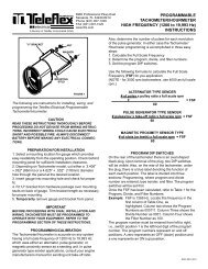
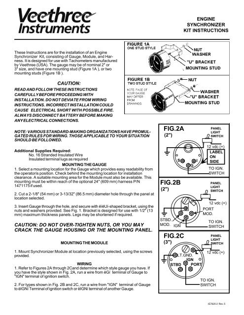
These Instructions are for the installation of an Engine<br />
Synchronizer Kit, consisting of Gauge, Module, and Harness.<br />
It is designed for use with Tachometers manufactured<br />
by <strong>Veethree</strong> (USA). The gauge may be of nominal 2" or<br />
3" size, and have one mounting stud (Figure 1A ), or two<br />
mounting studs (Figure 1B ).<br />
CAUTION:<br />
READ AND FOLLOW THESE INSTRUCTIONS<br />
CAREFULLY BEFORE PROCEEDING WITH<br />
INSTALLATION. DO NOT DEVIATE FROM WIRING<br />
INSTRUCTIONS. INCORRECT INSTALLATION COULD<br />
CAUSE ELECTRICAL SHORT WITH POSSIBLE FIRE.<br />
ALWAYS DISCONNECT BATTERY BEFORE MAKING<br />
ANY ELECTRICAL CONNECTIONS.<br />
NOTE: VARIOUS STANDARD-MAKING ORGANIZATIONS HAVE PROMUL-<br />
GATED RULES FOR WIRING. THOSE APPLICABLE TO YOUR SITUATION<br />
SHOULD BE FOLLOWED.<br />
Additional Supplies Required:<br />
No. 16 Stranded Insulated Wire<br />
Insulated terminal lugs as required<br />
MOUNTING THE GAUGE<br />
1. Select a mounting location for the Gauge which provides easy readability from<br />
the operatorís position. Check behind the mounting location for installation<br />
clearance. A suitable mounting area for the Module must also be available. This<br />
mounting must be within reach of the optional 24" (609 mm) harness P/N<br />
1471175 if used.<br />
2. Cut a 2-1/8" (54 mm) or 3-13/32" (86.5 mm) diameter hole through the panel at<br />
location selected.<br />
3. Insert Gauge through the hole, and secure with ëìëUí-shaped bracket, using the<br />
nuts and washers provided. See Fig. 1. Bracket is designed for use with 1/2" (13<br />
mm) maximum thickness panels. Legs may be shortened if required.<br />
CAUTION: DO NOT OVER-TIGHTEN NUTS, OR YOU MAY<br />
CRACK THE GAUGE HOUSING OR THE MOUNTING PANEL.<br />
MOUNTING THE MODULE<br />
1. Mount Synchronizer Module at location previously selected, using the screws<br />
provided.<br />
WIRING<br />
1. Refer to Figures 2A through 2Cand determine which style gauge you have. If<br />
you have the style shown in Fig. 2A, run a wire from ëGí terminal of Gauge to<br />
"IGN" terminal of ignition switch.<br />
2. For types shown in Fig. 2B and 2C, run a wire from "IGN" terminal of Gauge<br />
to ëIGNí Terminal of ignition switch or ëIGNí terminal of another Gauge.<br />
IE7825-2 Rev. 5
3. If lighting is desired:<br />
A.Type 2B and 2C:(Twist-in wedge base lamp)<br />
Run a wire from the ëLí (Light) terminal of Gauge<br />
to panel light switch or ëLí terminal of another<br />
Gauge. Run a wire from "LT GND" (Type 2C) or<br />
mounting stud terminal (Type2B) to electrical<br />
system ground.<br />
B. Type 2A: Connect one lead from lamp<br />
socket to panel light switch or ëLí terminal of<br />
another Gauge, and the second to electrical<br />
system ground.<br />
SOME MODELS LOOK<br />
LIKE THIS<br />
SEND IGN<br />
GRD<br />
SYNCH<br />
ADJUST<br />
4. Refer to Figure 3. Wiring shown will cause<br />
Gauge pointer (for types shown in Figures 2A and<br />
2B) to move in direction of faster <strong>engine</strong>. Type<br />
shown in Figure 2C will move towards slower<br />
<strong>engine</strong>. If desired, this may be changed by<br />
reversing connections at Module shown below<br />
and in Figure 3 ëAí and ëBí.<br />
A. Run a wire from sender (ëSí) terminal of<br />
Starboard Tachometer to Starboard <strong>engine</strong> tach<br />
terminal of Module.<br />
B. Run a wire from sender (ëSí) terminal of Port<br />
Tachometer to Port <strong>engine</strong> tach terminal of<br />
Module.<br />
5. Run a wire from Ground terminal of Module to<br />
electrical system ground.<br />
6. Refer to Figure 4, A through D, for your style<br />
gauge.<br />
For Types A, B, and C,connect Wiring Harness<br />
from Module to Gauge as shown in appropriate<br />
section of Figure 4, making sure plugs are fully<br />
seated on terminals.<br />
For Type D, cut molded plug off one end of<br />
harness. Install insulated ring terminals (not<br />
furnished) on leads of harness and connect to<br />
guage as shown in Figure 4D.<br />
Dual Station Applications:<br />
The preferred method is to use a Module for each<br />
gauge. The alternative is to use one Module, and<br />
wire the Gauges in parallel - that is, Ign to Ign,<br />
Port to Port, Stbd to Stbd. In this case, the<br />
Jumpers (Figure 3) must remain in place.<br />
When wiring is completed, reconnect Battery.<br />
Turn both keys ëOní - - Gauge pointer should be<br />
centered. If there is a problem, check electrical<br />
connections. Be sure ëIGNí and ëGRDí connections<br />
are not reversed.<br />
CAUTION:<br />
BEFORE RECONNECTING BATTERY, RECHECK<br />
WIRING TO ENSURE ALL CONNECTIONS ARE<br />
PROPERLY MADE. INCORRECT CONNECTIONS OR<br />
ELECTRICAL SHORTS COULD CAUSE DAMAGE OR<br />
FIRE. ELEMENTS OF ELECTRICAL SYSTEMS<br />
SHOULD HAVE PROPER FUSES INSTALLED.<br />
PAGE 2
OPERATION AND CALIBRATION<br />
1. Start <strong>engine</strong>s and observe readings of Tachometers<br />
and Synchronizer Gauge. Equal<br />
positioning of throttle levers should produce a<br />
center reading on Synchronizer Gauge. Pointer<br />
will deflect to side which has greater <strong>engine</strong><br />
speed (except for Type 2C).<br />
2. The Gauge and Module are calibrated for<br />
extreme accuracy in detecting differences in<br />
<strong>engine</strong> speeds. In some cases, it may be<br />
necessary to decrease the sensitivity of the unit.<br />
Removal of the Jumper tabs ( See Figure 3) on<br />
the Module will decrease sensitivity as shown on<br />
the Gauge. This means a greater difference of<br />
<strong>engine</strong> speeds will be required for an equal<br />
deflection of the Gauge pointer. If your application<br />
uses two Gauges from one Module, the Jumpers<br />
must not be removed.<br />
3. In extremely rare cases, it may be necessary<br />
to calibrate the unit. Make sure both <strong>engine</strong>s are<br />
running at the same speed. Temporarily remove<br />
the dust cover and insert a small bladed screwdriver<br />
in the calibration hole in the Module<br />
marked ëSYNCH ADJUSTí (See Figure 3). Rotate<br />
the adjustment screw in very small increments to<br />
change Gauge pointer deflection from either side<br />
of center. Do Not over-torque the adjustment or<br />
you will damage the Module.<br />
USA Sales/Support<br />
<strong>Veethree</strong> Electronics and Marine<br />
2420 Trailmate Drive<br />
Sarasota, FL 34243, USA<br />
Tel 941/538-7775<br />
Fax 941/775-1222<br />
techservice@veethree.com<br />
www.V3instruments.com<br />
PAGE 3