Split System Indoor Coils Installation Instructions - Nordyne
Split System Indoor Coils Installation Instructions - Nordyne
Split System Indoor Coils Installation Instructions - Nordyne
- No tags were found...

Create successful ePaper yourself
Turn your PDF publications into a flip-book with our unique Google optimized e-Paper software.
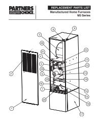
1. GENERAL INFORMATION<br />
C3QA/DA coils are designed for upflow and<br />
downflow furnace/air handler applications. The<br />
C3QA coils incorporate "single shot" coupling<br />
refrigerant connections for easy installation.<br />
The C3DA coils are furnished with down-turned<br />
refrigerant connections, ready for brazing.<br />
Read the installation manual supplied with the<br />
outdoor unit for refrigerant line connection procedure,<br />
required line sizes, and other information<br />
pertaining to the system installation.<br />
1. Make certain that the air delivery of the<br />
furnace/air handler is adequate to handle<br />
the static pressure drop of the coil, filter, and<br />
duct work.<br />
2. Check the orifice size of the coil's expansion<br />
device and confirm that it is suitable for<br />
application with the intended outdoor unit.<br />
3. Where precise forming of the refrigerant<br />
lines is required, a copper tubing bender<br />
designed for the size lines used is recommended.<br />
Avoid sharp bends and contact of<br />
the refrigerant lines with metal surfaces.<br />
4. Refrigerant lines should be wrapped<br />
with pressure sensitive neoprene or other<br />
suitable material where they pass through<br />
the raw edges of holes.<br />
5. The coil enclosure (if provided) and suction<br />
line must be insulated as needed to<br />
prevent condensate from forming and<br />
causing property damage.<br />
6. Coil must be level for proper condensate<br />
drainage.<br />
7. Do not remove seals from the coil until the<br />
tubing connections are ready to be made.<br />
NOTE: Optional cooling/heating equipment<br />
must be properly sized and installed in accordance<br />
with the furnace manufacturer’s specifications<br />
and approved recommendations. “Heating<br />
only” furnace air circulators may have to be<br />
replaced with multi-speed “Heating/Cooling”<br />
blowers to upgrade the air delivery (CFM) when<br />
an add-on coil is installed. Refer to Coil Specifications<br />
for recommended CFM and allow for<br />
pressure drop across the coil and filters.<br />
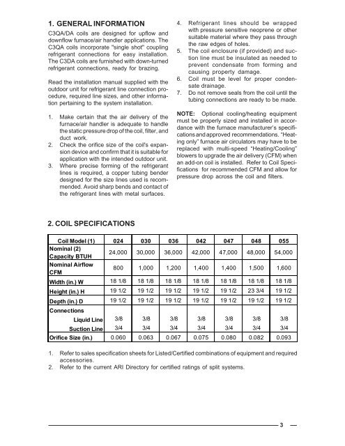
2. COIL SPECIFICATIONS<br />
Coil Model (1) 024 030 036 042 047 048 055<br />
Nominal (2)<br />
Capacity BTUH<br />
24,000 30,000 36,000 42,000 47,000 48,000 54,000<br />
Nominal Airflow<br />
CFM<br />
800 1,000 1,200 1,400 1,400 1,500 1,600<br />
Width (in.) W 18 1/8 18 1/8 18 1/8 18 1/8 18 1/8 18 1/8 18 1/8<br />
Height (in.) H 19 1/2 19 1/2 19 1/2 19 1/2 19 1/2 23 3/4 19 1/2<br />
Depth (in.) D 19 1/2 19 1/2 19 1/2 19 1/2 19 1/2 19 1/2 19 1/2<br />
Connections<br />
Liquid Line 3/8 3/8 3/8 3/8 3/8 3/8 3/8<br />
Suction Line 3/4 3/4 3/4 3/4 3/4 3/4 3/4<br />
Orifice Size (in.) 0.060 0.063 0.067 0.075 0.080 0.082 0.093<br />
1. Refer to sales specification sheets for Listed/Certified combinations of equipment and required<br />
accessories.<br />
2. Refer to the current ARI Directory for certified ratings of split systems.<br />
3