Druckschrift 99810454, New Broadcast Antenna Solutions for Digital ...
Druckschrift 99810454, New Broadcast Antenna Solutions for Digital ...
Druckschrift 99810454, New Broadcast Antenna Solutions for Digital ...

You also want an ePaper? Increase the reach of your titles
YUMPU automatically turns print PDFs into web optimized ePapers that Google loves.
DVB<br />
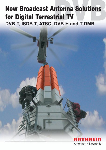
<strong>New</strong> <strong>Broadcast</strong> <strong>Antenna</strong> <strong>Solutions</strong><br />
<strong>for</strong> <strong>Digital</strong> Terrestrial TV<br />
DVB-T, ISDB-T, ATSC, DVB-H and T-DMB
Kathrein<br />
KATHREIN – The world’s leading antenna manufacturer<br />
Kathrein, founded in 1919, is an international company<br />
operating in the communications engineering field,<br />
focussed on the manufacture of antennas.<br />
For over 50 years Kathrein has been a reliable partner in<br />
the field of FM radio and TV transmitting antenna<br />
systems. Our strength lies in the customized solutions<br />
we offer <strong>for</strong> even the most difficult technical challenges,<br />
such as special radiation characteristics or protection<br />
against extreme environmental conditions.<br />
Kathrein not only offers top-quality components <strong>for</strong><br />
broadcasting systems, but also provides all related<br />
services.<br />
Recently, Kathrein has been developing a wide variety<br />
of new broadcast antenna solutions especially <strong>for</strong> digital<br />
audio and video broadcasting.<br />
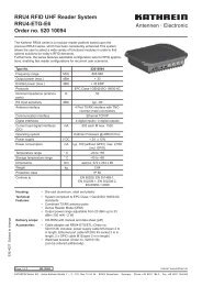
DVB-T antenna, Tuntex and Chien-Tai Building, Kaohsiung, Taiwan.<br />
With 378 m in height and 85 floors it is the seventh high building in the<br />
world.<br />
2<br />
Kathrein is the global market leader in the field of basestation<br />
antennas <strong>for</strong> cellular networks, with monthly<br />
production exceeding 100,000 units. Our customer-base<br />
includes all major system integrators, as well as over<br />
240 network operators world-wide. Kathrein’s basestations<br />
antennas not only offer impressive electrical<br />
specifications, but also focus on well thought-out<br />
mechanical design, resulting in outstanding product<br />
durability.<br />
From this vast experience with both broadcast as well<br />
as mobile communication customers, Kathrein is ideally<br />
prepared <strong>for</strong> the convergence of both technologies.<br />
<strong>Digital</strong> broadcasting is just under way, now being introduced<br />
all over the world, and Kathrein, as a technology<br />
leader, has also been participating with special antenna<br />
solutions in following countries so far:<br />
Albania<br />
Algeria<br />
Argentina<br />
Austria<br />
Brazil<br />
China<br />
Czech Republic<br />
France<br />
Germany<br />
Great Britain<br />
India<br />
Indonesia<br />
Ireland<br />
Italy<br />
Latvia<br />
Lithuania<br />
Myanmar<br />
Namibia<br />
Netherlands<br />
Norway<br />
Slovakia<br />
South Africa<br />
Spain<br />
Sweden<br />
Switzerland<br />
Taiwan<br />
Turkey<br />
United States<br />
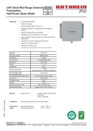
Photo on title page: Installation of UHF-DVB-T <strong>Antenna</strong> “Leipzig” (Germany) by Helicopter
DVB-T<br />
DVB-H / T-DMB trial projects in Germany<br />
DVB-T roll-out in Germany<br />
(Status July 2006)<br />
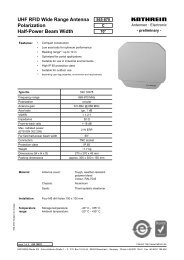
Germany has implemented a very tight schedule to fully convert its terrestrial television broadcasting systems from<br />
analogue to digital by 2010. Since 2003 Kathrein has been installing and modifying 50 antenna systems at major transmitting<br />
sites <strong>for</strong> the German Telekom T-Systems and the public broadcasting authorities.<br />
Eighteen of these antenna systems were put into place by helicopter. Even though this installation method was<br />
previously considered risky, Kathrein has been able to carry out this work without any complications or delays.<br />
1 Berlin Alexanderplatz<br />
2 Berlin Schäferberg<br />
3 Berlin Scholzplatz<br />
4 Cologne<br />
5 Bonn<br />
6 Hanover (Telemax Tower)<br />
7 Hanover (Hemmingen)<br />
8 Braunschweig (Broitzem)<br />
9 Braunschweig (Kraftwerk)<br />
10 Bremen<br />
11 Bremerhaven (Schiffdorf)<br />
12 Steinkimmen<br />
13 Frankfurt<br />
14 Wiesbaden<br />
15 Feldberg (Taunus District)<br />
16 Hamburg (Telemichel Tower)<br />
17 Hamburg (Rosengarten)<br />
18 Hamburg (Höltigbaum)<br />
19 Dortmund<br />
20 Wesel<br />
21 Essen<br />
22 Düsseldorf<br />
23 Langenberg<br />
24 Lübeck (Berkenthin)<br />
25 Lübeck (Stockelsdorf)<br />
26 Eutin (Bungsberg)<br />
27 Flensburg<br />
28 Kiel<br />
29 Schleswig<br />
30 Sibbesse<br />
31 Munich<br />
32 Wendelstein<br />
33 Nuremberg<br />
34 Dillberg<br />
35 Halle<br />
36 Leipzig<br />
37 Erfurt<br />
38 Marlow<br />
39 Neumünster<br />
40 Cuxhaven<br />
41 Stuttgart<br />
42 Heidelstein (Rhön District)<br />
43 Bielstein<br />
44 Heidelberg<br />
45 Wuppertal<br />
46 Minden<br />
47 Stadthagen<br />
48 Angelburg<br />
49 Kassel (Habichtswald)<br />
50 Würzberg<br />
DVB-H and T-DMB trial projects in the following metropoles:<br />
Berlin, Cologne, Frankfurt, Hamburg, Hanover, Munich, Stuttgart<br />
3
Main Transm<br />
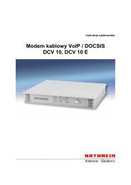
UHF Broadband <strong>Antenna</strong>s on Steel Carriers<br />
These arrays, consisting of newly- developed radomized 4-dipole panels, are designed <strong>for</strong> use in the UHF band<br />
470 – 862 MHz. Radiation patterns with smooth and very constant shapes over the entire UHF band help to avoid<br />
creating “bad channels”. Thus, these systems are extremely suitable <strong>for</strong> multi-channel, high-power master DTV stations.<br />
In order to increase the gain, stacking of up to 16 bays is possible, allowing a power-handling capacity of more than<br />
100 kW RMS. Interior access and climbing-safety installations (e.g. ASIR) are also possible.<br />
4<br />
• on square steel carrier or open mounting structures<br />
– Constant omni or directional pattern with circularity<br />
< ±2 dB<br />
– horizontal or vertical polarization<br />
– VSWR < 1.2 over whole band<br />
Horizontally polarized array<br />
4 panels per bay<br />
Panel model series K 72 32 4.<br />
270 90<br />
10<br />
• on octagonal steel carrier<br />
– Constant omni pattern with circularity<br />
< ±1.5 dB<br />
– vertical polarization<br />
– VSWR < 1.2 over whole band<br />
Vertically polarized array<br />
8 panels per bay<br />
Panel model series 750 10045<br />
3<br />
0<br />
dB<br />
0<br />
180<br />
0<br />
0<br />
180<br />
470 MHz<br />
550 MHz<br />
650 MHz<br />
750 MHz<br />
860 MHz<br />
470 MHz<br />
550 MHz<br />
650 MHz<br />
750 MHz<br />
860 MHz<br />
270 90<br />
10<br />
3<br />
dB<br />
Vertically polarized array<br />
4 panels per bay<br />
Panel model series K 73 32 4.<br />
270 90<br />
10<br />
3<br />
0<br />
0<br />
180<br />
Horizontal Patterns Horizontal Patterns<br />
Horizontal Patterns<br />
dB<br />
470 MHz<br />
550 MHz<br />
650 MHz<br />
750 MHz<br />
860 MHz
itter <strong>Antenna</strong>s<br />
UHF Broadband <strong>Antenna</strong>s in ∅ 1.6 m GRP Radome<br />
For stations where there are very harsh environmental conditions (snow/ice), antenna arrays that are fully covered<br />
by a GRP radome are recommended. For horizontal polarization and omnidirectional horizontal patterns, Superturnstile<br />
elements are used. For vertical polarization and omni or directional patterns, specially developed panels are<br />
implemented in square or octagonal structures.<br />
All the above solutions are offered fully broadband over the 470 – 862 MHz range, which makes them highly suitable <strong>for</strong><br />
multi-channel master DTV stations. In order to increase the gain, stacking of up to 16 bays is possible, allowing a power<br />
handling capacity of more than 100 kW RMS.<br />
• Superturnstile antenna<br />
– Constant omni pattern with circularity < ±1.5 dB<br />
– horizontal polarization<br />
– VSWR < 1.2 over whole band<br />
• Octagonal panel structure<br />
– Constant omni or directional pattern with circularity<br />
< ±1.5 dB<br />
– vertical polarization<br />
– VSWR < 1.2 over whole band<br />
– Building Block:<br />
Panel Model 750 10041<br />
Superturnstile antenna<br />
in GRP radome<br />
270 90<br />
10<br />
3<br />
Vertically polarized array in GRP radome<br />
8 panels per bay<br />
270 90<br />
10<br />
3<br />
0<br />
dB<br />
0<br />
180<br />
Horizontal Patterns<br />
0<br />
dB<br />
0<br />
180<br />
Horizontal Patterns<br />
470 MHz<br />
550 MHz<br />
650 MHz<br />
750 MHz<br />
860 MHz<br />
470 MHz<br />
550 MHz<br />
650 MHz<br />
750 MHz<br />
860 MHz<br />
5
UHF Omnidirectional <strong>Antenna</strong>s<br />
<strong>for</strong> Small to Medium-Power Sites<br />
6<br />
Gap<br />
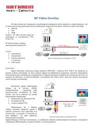
With the introduction of digital TV broadcasting, these services are now no longer restricted to stationary receivers with<br />
roof-top Rx antennas, but also permit portable and mobile reception. However, in order to achieve a satisfactory grade of<br />
coverage and to take account of the requirements <strong>for</strong> higher reference field strengths, gap-filling antennas may be<br />
necessary, at least in urban areas and metropoles. Some broadcasters may even wish to design their networks by using<br />
multiple small to medium power transmitters, similar to a cellular structure.<br />
Kathrein’s portfolio of antennas <strong>for</strong> these applications includes versions from 400 W to 15 kW, all fully-assembled <strong>for</strong><br />
plug-and-play installation. They come fully-radomized, thus featuring very low wind-load figures. This makes them<br />
especially suitable <strong>for</strong> DTV and DVB-H gap-filler stations.<br />
Collinear omnidirectional antennas, 400 W,<br />
K 73 20 4. series<br />
Type No. / Order No. 750 10114 750 10115 750 10116<br />
Frequency range 534 – 574 MHz 574 – 614 MHz 614 – 662 MHz<br />
VSWR < 1.5<br />
Gain (ref. λ/2-dipole) 7.5 dB 8 dB<br />
Polarization Vertical<br />
Max. power 400 W (at 50 °C ambient temperature)<br />
Wind load (at 160 km/h) 250 N<br />
Length 3113 mm<br />
Omnidirectional antenna, 750 W,<br />
K 73 20 4. series<br />
Type No. / Order No. 750 10060<br />
Frequency range 470 – 702 MHz<br />
VSWR < 1.4<br />
Gain (ref. λ/2-dipole) 3.0 – 4.5 dB<br />
Polarization Vertical<br />
Max. power 750 W (at 40 °C ambient temperature)<br />
Wind load (at 160 km/h) 225 N<br />
Height 1400 mm
iller <strong>Antenna</strong>s<br />
UHF Omnidirectional <strong>Antenna</strong>s<br />
<strong>for</strong> Small to Medium-Power Sites<br />
Omnidirectional antenna, 1000 W,<br />
K 73 20 4. series<br />
Type No. / Order No. 750 10062<br />
Frequency range 470 – 702 MHz<br />
VSWR < 1.4<br />
Gain (ref. λ/2-dipole) 5.5 – 7 dB<br />
Polarization Vertical<br />
Max. power 1 kW<br />
(at 40 °C ambient temperature)<br />
Wind load (at 160 km/h) 490 N<br />
Height 1927 mm<br />
Omnidirectional antenna, 15 kW,<br />
K 72 20 4. series<br />
Type No. / Order No. 750 10180<br />
Frequency range 470 – 862 MHz<br />
VSWR < 1.1<br />
Gain (ref. λ/dipole) 12.1 dB at mid-band<br />
Polarization Horizontal<br />
Max. power 15 kW<br />
(at 40 °C ambient temperature)<br />
Windload (at 160 km/h) 3350 N<br />
Height 8100 mm<br />
7
UHF Indoor <strong>Antenna</strong>s<br />
8<br />
Indoor<br />
A very important feature of terrestrial digital TV is the possibility to serve hand-held receivers, namely mobile phones and<br />
portable TV sets. Experts predict that around three quarters of the mobile-phone-television users will want to use this<br />
service indoors, i.e. <strong>for</strong> example in airport waiting lounges, exhibition halls etc... However, depending on the building<br />
structures concerned, building penetration losses of more than 10 dB may occur and make it almost impossible to<br />
achieve the necessary field strenghts created by the main transmitter stations only.<br />
For this reason, Kathrein has developed a variety of directional and omnidirectional indoor antennas especially suitable<br />
<strong>for</strong> DVB-H applications. Their shape and appearance, derived from mobile communications technology, is very<br />
inconspicuous and thus ideal <strong>for</strong> use in all such public places.<br />
Directional Indoor <strong>Antenna</strong><br />
Type No. / Order No. 750 10120 750 10122 750 10124<br />
Frequency range 470 – 534 MHz 534 – 614 MHz 614 – 702 MHz<br />
VSWR < 2.0<br />
Gain (ref. λ/2-dipole) Approx. 5 dB<br />
Polarization Vertical<br />
Max. power 50 W (at 50 °C ambient temperature)<br />
Height/width/depth 302 x 243 x 50 mm<br />
Bidirectional Indoor <strong>Antenna</strong><br />
Type No. / Order No. 750 10128<br />
Frequency range 470 – 702 MHz<br />
VSWR < 1.8<br />
Gain (ref. λ/2-dipole) 2 dB<br />
Polarization Vertical<br />
Max. power (total) 500 W (at 50 °C ambient temperature)<br />
Height/width/depth 310 / 55 / 190 mm<br />
Omnidirectional Indoor <strong>Antenna</strong><br />
Type No. / Order No. 750 10130 750 10131 750 10132<br />
Frequency range 470 – 558 MHz 550 – 638 MHz 574 – 702 MHz<br />
VSWR < 2.0<br />
Gain (ref. λ/2-dipole) Approx. 0 dB<br />
Polarization Vertical<br />
Max. power 50 W (at 50 °C ambient temperature)<br />
Diameter 258 mm<br />
Height 77 mm (without connector)<br />
90°<br />
10<br />
3 dB<br />
0<br />
Horizontal Pattern<br />
10<br />
3 dB<br />
0<br />
200°<br />
Horizontal Pattern
T-DMB<br />
L-Band <strong>Antenna</strong>s <strong>for</strong> Special Applications<br />
The L-Band has already been used <strong>for</strong> T-DAB broadcasting services <strong>for</strong> some time now. Recently, T-DMB (Terrestrial<br />
<strong>Digital</strong> Multimedia <strong>Broadcast</strong>ing) was introduced at these frequencies (1452 – 1480 MHz). Due to its stability against<br />
Doppler effects, T-DMB is a very practical standard <strong>for</strong> multimedia receiption in cars, but also used to provide TV <strong>for</strong><br />
hand-held receivers. The short wavelength of the L-Band requires very slim mounting structures or other techniques to<br />
achieve good omnidirectional patterns. For this purpose Kathrein has developed several versions of well-established<br />
L-Band panels <strong>for</strong> higher power and particular mounting applications:<br />
Omnidirectional or directional<br />
antenna array on steel tube<br />
Building block: Panel 750 10153<br />
P max = 400 W per panel<br />
Omnidirectional Indoor <strong>Antenna</strong><br />
Type No. / Order No. 800 10177<br />
Frequency range 824 – 960 MHz<br />
1425 – 2170 MHz<br />
VSWR 1425 – 1710 MHz: < 2.0<br />
Gain (ref. λ/2-dipole) Approx. 0 dB<br />
Polarization Vertical<br />
Max. power (per band) 50 W (at 50 °C ambient temperature)<br />
Diameter 265 mm<br />
Height 84 mm (without connector)<br />
Omnidirectional antenna array in<br />
GRP cylinder<br />
Building block: Panel 750 10099<br />
P max = 400 W per panel<br />
Models of L-Band panel 770 794<br />
VSWR < 1.25<br />
Gain 15 dBd<br />
65° half power beamwidth<br />
Height 1185 mm<br />
9
T-DMB<br />
L-Band <strong>Antenna</strong>s <strong>for</strong> Special Applications –<br />
Omnidirectional <strong>Antenna</strong> using Dual-Polarized Panels<br />
Especially with new services, such as DVB-H and T-DMB the broadcasters often face the problem of having only largediameter<br />
mast sections free <strong>for</strong> additional UHF and L-Band antennas. However, such mast sections do not permit the<br />
mounting of panels in a compact and centric way in order to create smooth omnidirectional patterns. The resulting deep<br />
minima caused by runtime delays may lead to blank spots in the coverage area.<br />
One adequate solution <strong>for</strong> avoiding this effect is the use of pairs of dual-polarized radiating elements, particularly <strong>for</strong><br />
mobile and portable services.<br />
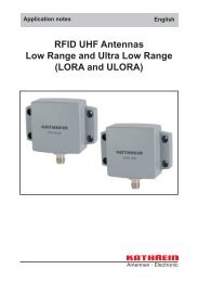
If the radiating elements are all polarized in the same way, the minima would be created by the runtime-delays of the<br />
overlapping signals of the different panels – see Figure 1.<br />
Figure 1: 4 panels vertically polarized mounted with radius of r/λ = 2<br />
Where dual-polarized pairs of panels are used as illustrated below, no deep minima will show up, because of the<br />
different polarizations in the overlapping zones. As a result, all variations of slant and elliptical polarization may be<br />
created at different angles, which will always provide good signal levels, but with different polarizations – see Figure 2.<br />
Figure 2: Two pairs of orthogonally polarized panels. This setup works<br />
even <strong>for</strong> large mounting radii r/λ<br />
Since the polarization varies in the coverage area, such an antenna system is especially suitable <strong>for</strong><br />
digital mobile and portable broadcasting services where the polarization of the receiving antennas is<br />
not precisely defined.<br />
10<br />
–45°<br />
r<br />
+45° +45°<br />
–45°<br />
r<br />
270 90<br />
10<br />
3<br />
0<br />
dB<br />
0<br />
180<br />
270 90<br />
10<br />
3<br />
0<br />
dB<br />
0<br />
180<br />
Models 750 10094 (+45°) and 750 10194 (–45°)<br />
L-Band <strong>Antenna</strong> Panel with 70° half-power beamwidth,<br />
3 ° electrical downtilt<br />
Max. power 500 W, height 1302 mm
RPCs<br />
Typical Reference Planning Configurations (RPCs)<br />
Technical Annex<br />
<strong>for</strong> DVB-T<br />
Source: ITU Regional Radiocommunication Conference RRC-06, Geneva<br />
Reference Frequencies: VHF 200 MHz; UHF 650 MHz<br />
Reference location probability: 95% (99% <strong>for</strong> mobile reception)<br />
11
In addition to the products and solutions shown in this brochure, Kathrein’s portfolio includes a full range of<br />
broadcast antennas and accessories <strong>for</strong> FM, TV MMDS, DAB and DTV. Kindly contact us <strong>for</strong> further in<strong>for</strong>mation<br />
or see our current broadcast catalogues:<br />
Internet: www.kathrein.de<br />
Catalogue<br />
<strong>Broadcast</strong> <strong>Antenna</strong> Systems<br />
Brochure<br />
50 Years of Kathrein FM and TV<br />
KATHREIN-Werke KG . Telephone +49 8031 184-0 . Fax +49 8031 184-495<br />
Anton-Kathrein-Straße 1 – 3 . P.O. Box 10 04 44 . D-83004 Rosenheim . Germany<br />
Catalogue<br />
Combiners and Filters <strong>for</strong> FM and TV<br />
CD-ROM<br />
<strong>Broadcast</strong> systems<br />
(includes all printed catalogues and brochures)<br />
9981.0454/0806/2/ZW/HA Subject to alteration.