dTRANS Lf 01 µP Transmitter / Controller for electrolytic conductivity
dTRANS Lf 01 µP Transmitter / Controller for electrolytic conductivity
dTRANS Lf 01 µP Transmitter / Controller for electrolytic conductivity
- No tags were found...

Create successful ePaper yourself
Turn your PDF publications into a flip-book with our unique Google optimized e-Paper software.
JUMO GmbH & Co. KG• 36035 Fulda, Germany<br />
Data Sheet 20.2540 Page 2/10<br />
Operation<br />
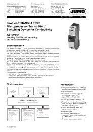
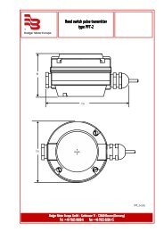
Indications / controls<br />
For easy programming and operation, the<br />
controller parameter and configuration<br />
data are assigned to various levels.<br />
(1)<br />
(2)<br />
(8)<br />
µS<br />
cm<br />
mS<br />
cm<br />
K1 K2 K3 K4<br />
(3)<br />
(4)<br />
(7)<br />
°C<br />
CAL<br />
PGM EXIT<br />
(5)<br />
(6)<br />
Code words protect the levels from<br />
unauthorized access.<br />
Membrane keys ensure simple and userfriendly<br />
operation.<br />
The two LED displays show the parameter<br />
symbols and the corresponding values.<br />
Operating level<br />
The lower display, <strong>for</strong> example, shows the<br />
symbol, the upper display shows the<br />
corresponding value. Setpoints SPr1 and<br />
SPr2 can be altered by using the<br />
membrane keys.<br />
(1) LED display in mS/cm (6) PGM key <strong>for</strong> selection of parameters<br />
and confirmation of entries<br />
(2) Status indicators (yellow)<br />
<strong>for</strong> outputs 1 to 4<br />
(3) Increment key <strong>for</strong> altering parameters<br />
or manual operation of relay K2<br />
(4) Decrement key <strong>for</strong> altering parameters<br />
or manual operation of relay K1<br />
(7) 4-digit temperature display<br />
(LED, green, 8mm high)<br />
(8) 4-digit process value indication<br />
(LED, red, 13mm high)<br />
(4)<br />
+<br />
(6)<br />
(5) EXIT key to leave the levels (3)<br />
+<br />
(5)<br />
“CAL”: Initiates calibration<br />
(relative cell constant K rel<br />
or temperature coefficient α )<br />
Initiate manual operation or hold<br />
Parameter level<br />
The controller is adapted to the control<br />
loop at this level. The appropriate<br />
parameters appear here, with symbol and<br />
value.<br />
Only those parameters will be indicated<br />
which correspond to the configuration of<br />
the controller (configuration level).<br />
Configuration level<br />
This level is used to adapt the controller to<br />
the control task, or <strong>for</strong> adaptation of the<br />
inputs and outputs.<br />
Calibration options<br />
❏ Calibration of the cell constant<br />
Subject to manufacturing tolerances, the<br />
cell constant of the <strong>conductivity</strong> measuring<br />
cell may deviate slightly from its nominal<br />
(printed) value. In addition, the cell<br />
constant may change during operation<br />
(due to deposits or wear). This results in a<br />
change of the output signal from the cell.<br />
The <strong>dTRANS</strong> <strong>Lf</strong> <strong>01</strong> offers the user the<br />
possibility of compensating any deviation<br />
from the nominal value of the cell constant<br />
through manual entry (range 80 — 120%)<br />
or automatic calibration of the relative cell<br />
constant K rel .<br />
❏ Calibration of the temperature<br />
coefficient α<br />
The <strong>conductivity</strong> of almost all solutions is<br />
temperature-dependent. To ensure correct<br />
measurement, it is there<strong>for</strong>e necessary to<br />
know both the temperature and<br />
temperature coefficient α [% per °C] of the<br />
measuring solution. The temperature can<br />
either be measured automatically, with a<br />
Pt100 or Pt1000 temperature probe, or set<br />
manually by the user.<br />
When using a <strong>dTRANS</strong> <strong>Lf</strong> <strong>01</strong>, the<br />
temperature coefficient can be determined<br />
automatically or entered manually, within<br />
the range 0 — 5.5 % per °C.<br />
Additional functions of the JUMO<br />
<strong>dTRANS</strong> <strong>Lf</strong> <strong>01</strong><br />
❏ Programmable response of the<br />
process value output to underrange /<br />
overrange<br />
On underrange or overrange, the<br />
process value output can move to the<br />
following operational states:<br />
-4%, 0%, 100% or 110% freely<br />
selectable<br />
Example: The instrument is<br />
programmed to<br />
4 — 20 mA corresponding to<br />
0 — 30 mS/cm<br />
The instrument can be set up so that, on<br />
exceeding 30 mS/cm, the output signal<br />
is either held at 20 mA (100%) or will<br />
jump to 22 mA (110%). The 22 mA value<br />
can then be recognized as “irregular” by<br />
a connected PLC.<br />
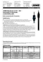
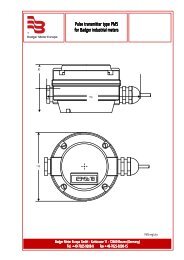
❏ Bilinear output<br />
This function divides the signal <strong>for</strong> the<br />
analog process value output into two linear<br />
portions (0 — 50% and 50 — 100% of the<br />
output signal), with a knee-point at 50% of<br />
the output signal. The knee-point of the<br />
characteristic can be shifted along the<br />
dotted 50% line. The 50% factory setting<br />
produces a straight-line characteristic.<br />
08.04/ 00362441