dTRANS Lf 01 µP Transmitter / Controller for electrolytic conductivity
dTRANS Lf 01 µP Transmitter / Controller for electrolytic conductivity
dTRANS Lf 01 µP Transmitter / Controller for electrolytic conductivity
- No tags were found...

Create successful ePaper yourself
Turn your PDF publications into a flip-book with our unique Google optimized e-Paper software.
JUMO GmbH & Co. KG<br />
Delivery address:Mackenrodtstraße 14,<br />
36039 Fulda, Germany<br />
Postal address: 36035 Fulda, Germany<br />
Phone: +49 661 6003-0<br />
Fax: +49 661 6003-607<br />
E-mail: mail@jumo.net<br />
Internet: www.jumo.net<br />
JUMO Instrument Co. Ltd.<br />
JUMO House<br />
Temple Bank, Riverway<br />
Harlow, Essex CM 20 2TT, UK<br />
Phone: +44 12 79 63 55 33<br />
Fax: +44 12 79 63 52 62<br />
E-mail: sales@jumo.co.uk<br />
Internet: www.jumo.co.uk<br />
JUMO PROCESS CONTROL INC.<br />
885 Fox Chase, Suite 103<br />
Coatesville PA 19320, USA<br />
Phone: 610-380-8002<br />
1-800-554-JUMO<br />
Fax: 610-380-8009<br />
E-mail: info@JumoUSA.com<br />
Internet: www.JumoUSA.com<br />
Data Sheet 20.2540<br />
Page 1/10<br />
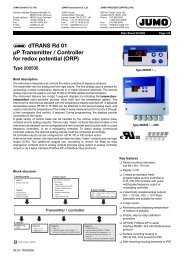
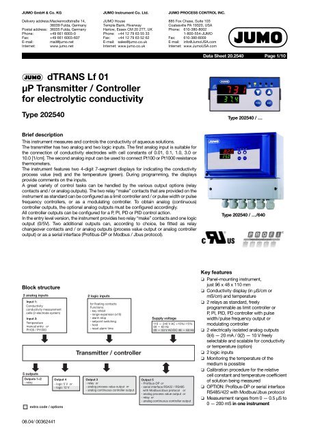
<strong>dTRANS</strong> <strong>Lf</strong> <strong>01</strong><br />
µP <strong>Transmitter</strong> / <strong>Controller</strong><br />
<strong>for</strong> <strong>electrolytic</strong> <strong>conductivity</strong><br />
Type 202540<br />
Type 202540 / …<br />
Brief description<br />
This instrument measures and controls the <strong>conductivity</strong> of aqueous solutions.<br />
The transmitter has two analog and two logic inputs. The first analog input is suitable <strong>for</strong><br />
the connection of <strong>conductivity</strong> electrodes with cell constants of 0.<strong>01</strong>, 0.1, 1.0, 3.0 or<br />
10.0 [1/cm]. The second analog input can be used to connect Pt100 or Pt1000 resistance<br />
thermometers.<br />
The instrument features two 4-digit 7-segment displays <strong>for</strong> indicating the <strong>conductivity</strong><br />
process value (red) and the temperature (green). During programming, the displays<br />
provide comments on the inputs.<br />
A great variety of control tasks can be handled by the various output options (relay<br />
contacts and / or analog outputs). The two relay “make” contacts that are provided on the<br />
instrument as standard can be configured as a limit controller and / or pulse width or pulse<br />
frequency controllers, or as a modulating controller. To obtain analog (continuous)<br />
controller outputs, the optional analog outputs must be configured accordingly.<br />
All controller outputs can be configured <strong>for</strong> a P, PI, PD or PID control action.<br />
In the entry level version, the instrument provides two relay “make” contacts and one logic<br />
output (0/5V). Two additional outputs can, according to choice, be fitted as relay<br />
changeover contacts and / or analog outputs (process value output or analog controller<br />
output) or as a serial interface (Profibus-DP or Modbus / Jbus protocol).<br />
Type 202540 / …/640<br />
Block structure<br />
Special features<br />
Key features<br />
❏ Panel-mounting instrument,<br />
just 96 x 48 x 110 mm<br />
❏ Conductivity display (in µS/cm or<br />
mS/cm) and temperature<br />
❏ 2 relays as standard, freely<br />
programmable as limit controller or<br />
P, PI, PID, PD controller with pulse<br />
width/pulse frequency output or<br />
modulating controller<br />
❏ 2 electrically isolated analog outputs<br />
0(4) — 20 mA / 0(2) — 10 V freely<br />
selectable and scalable <strong>for</strong> <strong>conductivity</strong><br />
or temperature (option)<br />
❏ 2 logic inputs<br />
❏ Monitoring the temperature of the<br />
medium is possible<br />
❏ Calibration procedure <strong>for</strong> the relative<br />
cell constant and temperature coefficient<br />
of solution being measured<br />
❏ OPTION: Profibus-DP or serial interface<br />
RS485/422 with Modbus/Jbus protocol<br />
❏ Measurement ranges from 0 — 0.5 µS to<br />
0—200mS in one instrument<br />
08.04/ 00362441
JUMO GmbH & Co. KG• 36035 Fulda, Germany<br />
Data Sheet 20.2540 Page 2/10<br />
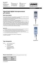
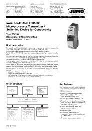
Operation<br />
Indications / controls<br />
For easy programming and operation, the<br />
controller parameter and configuration<br />
data are assigned to various levels.<br />
(1)<br />
(2)<br />
(8)<br />
µS<br />
cm<br />
mS<br />
cm<br />
K1 K2 K3 K4<br />
(3)<br />
(4)<br />
(7)<br />
°C<br />
CAL<br />
PGM EXIT<br />
(5)<br />
(6)<br />
Code words protect the levels from<br />
unauthorized access.<br />
Membrane keys ensure simple and userfriendly<br />
operation.<br />
The two LED displays show the parameter<br />
symbols and the corresponding values.<br />
Operating level<br />
The lower display, <strong>for</strong> example, shows the<br />
symbol, the upper display shows the<br />
corresponding value. Setpoints SPr1 and<br />
SPr2 can be altered by using the<br />
membrane keys.<br />
(1) LED display in mS/cm (6) PGM key <strong>for</strong> selection of parameters<br />
and confirmation of entries<br />
(2) Status indicators (yellow)<br />
<strong>for</strong> outputs 1 to 4<br />
(3) Increment key <strong>for</strong> altering parameters<br />
or manual operation of relay K2<br />
(4) Decrement key <strong>for</strong> altering parameters<br />
or manual operation of relay K1<br />
(7) 4-digit temperature display<br />
(LED, green, 8mm high)<br />
(8) 4-digit process value indication<br />
(LED, red, 13mm high)<br />
(4)<br />
+<br />
(6)<br />
(5) EXIT key to leave the levels (3)<br />
+<br />
(5)<br />
“CAL”: Initiates calibration<br />
(relative cell constant K rel<br />
or temperature coefficient α )<br />
Initiate manual operation or hold<br />
Parameter level<br />
The controller is adapted to the control<br />
loop at this level. The appropriate<br />
parameters appear here, with symbol and<br />
value.<br />
Only those parameters will be indicated<br />
which correspond to the configuration of<br />
the controller (configuration level).<br />
Configuration level<br />
This level is used to adapt the controller to<br />
the control task, or <strong>for</strong> adaptation of the<br />
inputs and outputs.<br />
Calibration options<br />
❏ Calibration of the cell constant<br />
Subject to manufacturing tolerances, the<br />
cell constant of the <strong>conductivity</strong> measuring<br />
cell may deviate slightly from its nominal<br />
(printed) value. In addition, the cell<br />
constant may change during operation<br />
(due to deposits or wear). This results in a<br />
change of the output signal from the cell.<br />
The <strong>dTRANS</strong> <strong>Lf</strong> <strong>01</strong> offers the user the<br />
possibility of compensating any deviation<br />
from the nominal value of the cell constant<br />
through manual entry (range 80 — 120%)<br />
or automatic calibration of the relative cell<br />
constant K rel .<br />
❏ Calibration of the temperature<br />
coefficient α<br />
The <strong>conductivity</strong> of almost all solutions is<br />
temperature-dependent. To ensure correct<br />
measurement, it is there<strong>for</strong>e necessary to<br />
know both the temperature and<br />
temperature coefficient α [% per °C] of the<br />
measuring solution. The temperature can<br />
either be measured automatically, with a<br />
Pt100 or Pt1000 temperature probe, or set<br />
manually by the user.<br />
When using a <strong>dTRANS</strong> <strong>Lf</strong> <strong>01</strong>, the<br />
temperature coefficient can be determined<br />
automatically or entered manually, within<br />
the range 0 — 5.5 % per °C.<br />
Additional functions of the JUMO<br />
<strong>dTRANS</strong> <strong>Lf</strong> <strong>01</strong><br />
❏ Programmable response of the<br />
process value output to underrange /<br />
overrange<br />
On underrange or overrange, the<br />
process value output can move to the<br />
following operational states:<br />
-4%, 0%, 100% or 110% freely<br />
selectable<br />
Example: The instrument is<br />
programmed to<br />
4 — 20 mA corresponding to<br />
0 — 30 mS/cm<br />
The instrument can be set up so that, on<br />
exceeding 30 mS/cm, the output signal<br />
is either held at 20 mA (100%) or will<br />
jump to 22 mA (110%). The 22 mA value<br />
can then be recognized as “irregular” by<br />
a connected PLC.<br />
❏ Bilinear output<br />
This function divides the signal <strong>for</strong> the<br />
analog process value output into two linear<br />
portions (0 — 50% and 50 — 100% of the<br />
output signal), with a knee-point at 50% of<br />
the output signal. The knee-point of the<br />
characteristic can be shifted along the<br />
dotted 50% line. The 50% factory setting<br />
produces a straight-line characteristic.<br />
08.04/ 00362441
JUMO GmbH & Co. KG • 36035 Fulda, Germany<br />
Data Sheet 20.2540 Page 3/10<br />
The bilinear characteristic is used when the<br />
“normal” measurement range is likely to be<br />
frequently exceeded.<br />
Example: The normal measurement range<br />
spans 0 — 20 µS/cm.<br />
However, measurements of up to 80 µS/<br />
cm can also occur.<br />
In this case, the range 0 — 100 µS/cm will<br />
be selected, and the knee-point set at 20%<br />
of this range (20% of 100 µS/cm<br />
corresponds to 20 µS/cm).<br />
This results in measurements in the range<br />
0 — 20 µS/cm being converted into an<br />
output signal 0 — 10 mA.<br />
Measurements in the range 20 — 100 µS/<br />
cm will be converted into an output signal<br />
10 — 20 mA.<br />
❏ The response of the controller relays<br />
to “Hold” can be defined<br />
“Hold” is initiated either manually, using<br />
the keys, by a logic input, or by an alarm<br />
event. The outputs of the relays K1 and<br />
K2 can move to the following<br />
(programmable) states on “Hold”:<br />
0% Relay de-energized<br />
50% output For dynamic<br />
controllers, 50% of the<br />
maximum pulse width<br />
or frequency is<br />
produced<br />
100% output Relay is energized, or<br />
maximum pulse width<br />
/ frequency<br />
Output<br />
accepted<br />
The present output<br />
continues to be<br />
produced<br />
❏ In “Manual” mode, the relays K1 and<br />
K2 are operated manually, by using<br />
the keys. Either key or switch operation<br />
can be selected, by a setting at the<br />
parameter level.<br />
Key operation: The relay is switched as<br />
long as the key is pressed (e.g. <strong>for</strong><br />
manual dosing).<br />
Switch operation: The first key stroke<br />
switches the relay on – the second<br />
switches it off again (toggle action), e.g.<br />
<strong>for</strong> emptying large tanks.<br />
❏ Simulation of the process value<br />
output<br />
In the manual mode, the process value<br />
output (0/2 — 10 V or 0/4 — 20 mA, depending<br />
on the setting) can be switched<br />
in 10% steps from 0 — 100%, .<br />
Application: “Dry-run” commissioning of<br />
the plant (without measuring cell, fault<br />
search, servicing).<br />
❏ <strong>Controller</strong> output functions<br />
Output 1 (relay): Switching, with pulse<br />
frequency or pulse width action / limit<br />
monitoring / switched off. Switching<br />
function can be reversed.<br />
MAX / MIN limit comparator.<br />
Output 2 (relay): Switching, with pulse<br />
frequency or pulse width action / limit<br />
monitoring / MAX / MIN limit comparator<br />
<strong>for</strong> temperature / switched off. Switching<br />
function can be reversed.<br />
MAX / MIN limit comparator.<br />
Output 3, relay or analog process value<br />
output: “Hold” / alarm pulse contact;<br />
alarm steady contact / MAX / MIN<br />
comparator <strong>for</strong> temperature input /<br />
output of <strong>conductivity</strong> process value<br />
(only <strong>for</strong> analog process value output) /<br />
output of temperature process value<br />
(only <strong>for</strong> analog process value output) /<br />
analog controller output (only <strong>for</strong> analog<br />
process value output) / no function.<br />
Output 4, logic output: “Hold“ / alarm<br />
pulse contact / alarm steady contact /<br />
MAX limit comparator <strong>for</strong> temperature<br />
input / MIN limit comparator <strong>for</strong><br />
temperature input / no function.<br />
Output 5, relay or analog process value<br />
output: “Hold” / alarm pulse contact;<br />
alarm steady contact / MAX / MIN limit<br />
comparator / output of <strong>conductivity</strong><br />
process value (only <strong>for</strong> analog process<br />
value output) / output of temperature<br />
process value (only <strong>for</strong> analog process<br />
value output) / analog controller output<br />
(only <strong>for</strong> analog process value output) /<br />
no function.<br />
Limit comparator<br />
(limit monitor)<br />
<strong>Controller</strong> outputs 1 to 5 (depending on<br />
the instrument version) can be assigned to<br />
a limit-monitoring function.<br />
For each one, the direction of switching<br />
(pulled in on going above, or going below a<br />
limit), pull-in and/or drop-out delay, and a<br />
hysteresis can all be defined.<br />
Interface<br />
The microprocessor/controller can be<br />
optionally fitted with an RS422/RS485<br />
interface. This is used <strong>for</strong> communication<br />
with higher-level systems and integration<br />
into a data network. The transmission<br />
protocol can be either Profibus-DP or<br />
Modbus/Jbus.<br />
Technical data<br />
Inputs<br />
Analog input 1<br />
Electrolytic <strong>conductivity</strong> cell, with cell<br />
constants: 0.<strong>01</strong>, 0.1, 1.0, 3.0, 10.0 [1/cm]<br />
(2-electrode principle).<br />
The cell constants can be adjusted over a<br />
range 80 — 120%.<br />
Lead compensation, input 1<br />
The influence of long cables in the<br />
measuring ranges above 20 mS/cm can be<br />
compensated by entering the lead<br />
resistance, in the range 0.00 to 9.99 Ω.<br />
Analog input 2<br />
Resistance thermometer Pt100 or<br />
Pt 1000, in 2- or 3-wire circuit<br />
-50 to +250°C<br />
Measurement display in °C or °F<br />
Lead compensation, analog input 2<br />
The lead resistance can be compensated<br />
in software by a correction of the process<br />
value.<br />
This is not required if the resistance<br />
thermometer is connected in a 3-wire<br />
circuit.<br />
When a resistance thermometer is<br />
connected in a 2-wire circuit, lead<br />
compensation can be provided by using an<br />
external compensation resistor.<br />
Functional description of logic inputs 1<br />
and 2<br />
The two standard logic inputs can be<br />
operated by floating contacts (relays) from<br />
a PLC, or by switches. The following<br />
functions can be selected and assigned:<br />
Key inhibit: The PLC or a key switch can be<br />
used to lock the keys on the transmitter, to<br />
prevent unauthorized entries being made.<br />
Setpoint changeover: For com<strong>for</strong>table<br />
process control. As long as the logic input<br />
is not operated, setpoint pair SPr1 and<br />
SPr2 is active. If the appropriately<br />
configured logic input is operated, then the<br />
second setpoint pair is activated (setpoint<br />
switching).<br />
Freeze measurement: The indicated<br />
measurement and the process value<br />
output no longer change.<br />
“Hold”: This function can be used (<strong>for</strong><br />
instance, by a supervisory PLC) to put the<br />
instrument into the secure “Hold” state.<br />
The response of the controller to “Hold” is<br />
as previously defined.<br />
“Hold reversed”: The same function as <strong>for</strong><br />
HOLD, but when the logic input is open.<br />
Alarm stop: The alarm generation via the<br />
configured output is reset or prevented,<br />
but the alarm LED (e.g. K4) continues to<br />
blink as a warning.<br />
08.04/ 00362441
JUMO GmbH & Co. KG • 36035 Fulda, Germany<br />
Data Sheet 20.2540 Page 4/10<br />
Reset alarm time: The alarm generation via<br />
the configured output is prevented. The<br />
alarm delay time is set to zero, but is<br />
restarted when the logic input becomes<br />
inactive and the start conditions are fulfilled<br />
once more. The alarm LED (e.g. K4)<br />
continues to blink as a warning.<br />
Range expansion (x10): If only a small<br />
portion of the measurement range is used,<br />
it may be advantageous <strong>for</strong> the transmitter<br />
to react to 0 — 10% of the process value<br />
by producing 0 — 100% of the output<br />
signal.<br />
Measurement and control range<br />
0 — 0.5 µS to 0 — 200 mS, depending on<br />
the cell constant, see table on page 5.<br />
Deviation from characteristic<br />
≤ 1.0% of measurement range<br />
Ambient temperature error<br />
≤ 0.25% per 10 °C<br />
Reference temperature<br />
25°C<br />
Temperature display<br />
-50 to +250°C (can be switched to °F)<br />
Deviation from characteristic<br />
≤ 0.25% of measurement range<br />
Ambient temperature error<br />
≤ 0.1% per 10 °C<br />
Outputs<br />
2 relay outputs, 1 logic output, 1 analog<br />
process value output or 1 additional relay,<br />
and 1 serial interface are available.<br />
1. Relay, output 1 / 2 (standard)<br />
Make contact (n.o., can also be<br />
configured as n.c. break contact)<br />
contact rating: 3A, 250V AC<br />
with resistive load<br />
contact life:<br />
> 5x10 5 operations at rated load<br />
2. Logic output, output 4<br />
0/5V R load ≥ 250Ω (standard)<br />
or<br />
0/12V R load ≥ 650Ω (option)<br />
3. Process value output, output 3 or 5<br />
(option)<br />
freely configurable:<br />
0(2) — 10V R load ≥ 500Ω or<br />
0(4) — 20mA R load ≥ 500Ω<br />
electrically isolated from the inputs:<br />
∆U ≤ 30V AC or<br />
∆U ≤ 50V DC.<br />
Deviation from characteristic<br />
of the output signal<br />
≤ 0.25% ± 50 ppm per °C<br />
4. Relay, output 3 or 5 (option)<br />
(only <strong>for</strong> instruments without a process<br />
value output)<br />
changeover contact<br />
contact rating: 3A, 250V AC<br />
with resistive load<br />
contact life:<br />
> 5x10 5 operations at rated load<br />
08.04/ 00362441<br />
5. Interface RS422 / RS485,<br />
Output 5 (option)<br />
electrically isolated<br />
Baud rate<br />
4800 / 9600bps<br />
Protocol<br />
Modbus / Jbus or<br />
Profibus-DP<br />
General controller data<br />
A/D converter<br />
resolution > 15 bit<br />
<strong>Controller</strong> type<br />
Outputs 1 and 2<br />
limit controller and / or pulse width or pulse<br />
frequency controller, modulating<br />
controller. Freely configurable and mixable<br />
K3 / K5:<br />
continuous controller<br />
Control action<br />
configurable as P, PI, PID or PD.<br />
Sampling time<br />
210 msec<br />
Measuring circuit monitoring<br />
Input 1:<br />
out-of-range, sensor monitoring<br />
Input 2:<br />
out-of-range, probe short-circuit,<br />
probe break<br />
The outputs move to a defined<br />
(configurable) status.<br />
Data backup<br />
EEPROM<br />
Supply voltage<br />
110 — 240 V AC +10%/-15%,<br />
48 — 63 Hz or<br />
20 — 53 V AC/DC, 48 — 63 / 0 Hz,<br />
Power consumption<br />
approx. 8V A<br />
Electrical connection<br />
Instrument <strong>for</strong> switchgear cabinet<br />
(basic version)<br />
via gold-plated faston connectors to<br />
DIN 46 244/A; 4.8mm x 0.8mm<br />
Wall-mounting housing<br />
(extra code /640)<br />
via screw terminals<br />
(wire cross-section up to 2.5 mm 2 )<br />
6 cable glands (1 x M16, 5 x M20<br />
Permissible<br />
ambient temperature<br />
0 to +50°C<br />
Permissible<br />
ambient temperature limits<br />
-10 to +55°C<br />
Permissible storage temperature<br />
-40 to +70°C<br />
Climatic conditions<br />
rel. humidity ≤ 75%, no condensation<br />
Enclosure protection<br />
to EN 60 529<br />
Instrument <strong>for</strong> switchgear cabinet<br />
front IP65 / rear IP20<br />
Wall-mounting instrument<br />
IP67<br />
Electrical safety<br />
to EN 61 <strong>01</strong>0<br />
clearance and creepage distances <strong>for</strong><br />
- overvoltage category II<br />
- pollution degree 2<br />
Electromagnetic compatibility<br />
to EN 61 326<br />
interference emission:<br />
interference immunity:<br />
Class B<br />
to industrial<br />
requirements<br />
Housing<br />
Instrument <strong>for</strong> switchgear cabinet<br />
(basic version)<br />
panel-mounting housing in conductive<br />
plastic to DIN 43 700, base material ABS<br />
with plug-in controller module.<br />
Wall-mounting housing<br />
(extra code /640)<br />
base material PC<br />
Operating position<br />
unrestricted<br />
Weight<br />
Instrument <strong>for</strong> switchgear cabinet<br />
(basic version)<br />
approx. 320g<br />
Wall-mounting housing (extra code /640)<br />
approx. 1400 g<br />
Option<br />
Wall-mounting housing<br />
extra code /640<br />
On request, the JUMO <strong>dTRANS</strong> <strong>Lf</strong> <strong>01</strong> can<br />
be supplied built into a surface-mounting<br />
housing. The housing is suitable <strong>for</strong> wallmounting<br />
or <strong>for</strong> mounting on a 35 x 7.5 mm<br />
DIN rail to EN 50 022.<br />
The housing is sturdy and provides IP67<br />
protection <strong>for</strong> the built-in instrument and is<br />
fitted with six cable glands. Unused cable<br />
glands can be tightly sealed using the blind<br />
grommets that are included in the delivery.<br />
The electrical connection is made via<br />
screw terminals (wire cross-section up to<br />
2.5 mm 2 ).<br />
Standard accessories<br />
– 2 mounting brackets (not with extra<br />
code /640 (wall-mounting housing))<br />
– 1 seal <strong>for</strong> panel-mounting (not with<br />
extra code /640 (wall-mounting<br />
housing))<br />
– sundry items <strong>for</strong> wall-mounting (only<br />
with extra code /640 (wall-mounting<br />
housing))<br />
– sundry items <strong>for</strong> DIN rail mounting (only<br />
with extra code /640 (wall-mounting<br />
housing))<br />
– 1 Operating Manual B 20.2540.0.1<br />
Optional accessory<br />
Interface Description B 20.2530.2
JUMO GmbH & Co. KG• 36035 Fulda, Germany<br />
Data Sheet 20.2540 Page 5/10<br />
Cell constants and measurement ranges<br />
Cell constant<br />
Meas. range B) Display with configured measurement<br />
K B) (C111)<br />
µS mS<br />
0.<strong>01</strong> 0 — 0.500 µS/cm 0.500 – – A) 1<br />
0.<strong>01</strong> 0 — 2.000 µS/cm 2.000 – – A) 2<br />
0.<strong>01</strong> 0 — 10.00 µS/cm 10.00 – – A) 3<br />
0.1 0 — 5.000 µS/cm 5.000 – – A) 4<br />
0.1 0 — 20.00 µS/cm 20.00 – – A) 5<br />
0.1 0 — 100.0 µS/cm 100.0 – – A) 6<br />
0.1 0 — 1.000 mS/cm 1000 1.000 7<br />
0.1 0 — 5.000 mS/cm 5000 5.000 8<br />
1.0 0 — 50.00 µS/cm 50.00 – – A) 9<br />
1.0 0 — 100.0 µS/cm 100.0 – – A) 10<br />
1.0 0 — 1.000 mS/cm 1000 1.000 11<br />
1.0 0 — 5.000 mS/cm 5000 5.000 12<br />
1.0 0 — 20.00 mS/cm – – A) 20.00 13<br />
1.0 0 — 100.0 mS/cm – – A) 100.0 14<br />
3.0 0 — 1.000 mS/cm 1000 1.000 15<br />
3.0 0 — 5.000 mS/cm 5000 5.000 16<br />
3.0 0 — 30.00 mS/cm – – A) 30.00 17<br />
10.0 0 — 30.00 mS/cm – – A) 30.00 18<br />
10.0 0 — 200.0 mS/cm – – A) 200.0 19<br />
A) These settings are not permissible – they would cause an incorrect display<br />
B) The selection of the measurement range and cell constant is made through the code number “Range”<br />
Range<br />
(rAng)<br />
Parameters<br />
Parameter Display Value range Comment<br />
Alarm tolerance AL1 0.000 — 9999*<br />
The alarm is only generated when the level<br />
(setpoint + alarm tolerance) has been<br />
passed, and the alarm delay time has<br />
elapsed<br />
Alarm delay AL2 0 — 6000 sec<br />
Delay time be<strong>for</strong>e the alarm contact is<br />
activated<br />
Proportional band 1<br />
Pb1<br />
Proportional band 2<br />
Pb2<br />
1 — 9999* Influences the P action of the controller<br />
Derivative time 1<br />
dt1<br />
Influences the D action of the controller<br />
Derivative time 2<br />
dt2<br />
If dt = 0, the controller has no D action.<br />
0 — 9999 sec<br />
Reset time 1 rt1 Influences the I action of the controller<br />
Reset time 2<br />
rt2<br />
If rt = 0, the controller has no I action.<br />
Minimum ON time 1<br />
(<strong>for</strong> limit controller or<br />
pulse width controller)<br />
or<br />
minimum pulse width 1<br />
(<strong>for</strong> pulse frequency controller)<br />
Minimum ON time 2<br />
(<strong>for</strong> limit controller or<br />
pulse width controller)<br />
or<br />
minimum pulse width 2<br />
(<strong>for</strong> pulse frequency controller)<br />
tr1<br />
tr2<br />
0.2 — 999.9 sec<br />
Determined by the technical data of the<br />
dosing device (solenoid valve, dosing pump)<br />
08.04/ 00362441
JUMO GmbH & Co. KG • 36035 Fulda, Germany<br />
Data Sheet 20.2540 Page 6/10<br />
Parameter Display Value range Comment<br />
Switching differential 1<br />
Switching differential 2<br />
Switching differential 3<br />
Switching differential 4<br />
Switching differential 5<br />
Pull-in delay 1<br />
Pull-in delay 2<br />
Pull-in delay 3<br />
Pull-in delay 4<br />
Pull-in delay 5<br />
Drop-out delay 1<br />
* Decimal point and dimensional unit corresponding to chosen range<br />
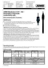
Connection diagram<br />
HYS1<br />
HYS2<br />
HYS3<br />
HYS4<br />
HYS5<br />
Ond1<br />
Ond2<br />
Ond3<br />
Ond4<br />
Ond5<br />
Ofd1<br />
1 — 9999*<br />
Defines the switch-off point <strong>for</strong> the control<br />
contacts<br />
0.0 — 999.9 sec Delay time be<strong>for</strong>e the contact is activated<br />
Drop-out delay 2<br />
Ofd2<br />
Drop-out delay 3<br />
Ofd3 0.2 — 999.9 sec<br />
Delay time until the contact moves back to<br />
the initial position<br />
Drop-out delay 4<br />
Ofd4<br />
Drop-out delay 5<br />
Ofd5<br />
Pulse frequency 1<br />
Fr1<br />
Maximum frequency of pulses (operating a<br />
0 — 150 pulses/min<br />
Pulse frequency 2<br />
Fr2<br />
dosing pump, <strong>for</strong> instance)<br />
Pulse period 1<br />
Cy1<br />
Pulse period 2<br />
Cy2<br />
2.0 — 999.9 sec The period in which a pulse is modulated<br />
Output level limit, output 1 Y1<br />
The maximum output level <strong>for</strong> a pulse width /<br />
0 — 100%<br />
Output level limit, output 2 Y2<br />
pulse frequency controller<br />
Actuator time tt 15 — 3000 sec For modulating controller<br />
17 19<br />
18<br />
20<br />
21<br />
22<br />
23<br />
N<br />
L1<br />
(L-)<br />
(L+) TE<br />
Rear view with<br />
faston connectors<br />
16<br />
15<br />
14<br />
1<br />
2<br />
3<br />
13<br />
12<br />
11<br />
10<br />
9 7<br />
8<br />
5<br />
6 4<br />
Wall-mounting housing<br />
(extra code /640)<br />
with terminal strip<br />
Outputs K Connections Symbol<br />
Relay 1<br />
(K1)<br />
Status indication<br />
LED K1<br />
1 23<br />
22<br />
common<br />
make<br />
23 22<br />
P<br />
S<br />
Relay 2<br />
(K2)<br />
Status indication<br />
LED K2<br />
2 21<br />
20<br />
common<br />
make<br />
21 20<br />
P<br />
S<br />
08.04/ 00362441
JUMO GmbH & Co. KG • 36035 Fulda, Germany<br />
Data Sheet 20.2540 Page 7/10<br />
Relay 3<br />
(K3)<br />
Status indication<br />
LED K3<br />
3 16<br />
15<br />
14<br />
break<br />
common<br />
make<br />
16 15 14<br />
P<br />
Ö S<br />
or<br />
analog process value output<br />
(electrically isolated)<br />
15<br />
14<br />
–<br />
+<br />
14 15<br />
+ -<br />
Logic output 1<br />
(K4)<br />
Status indication<br />
LED K4<br />
4 19<br />
17<br />
–<br />
+<br />
17 19<br />
+ -<br />
Relay 4<br />
(K5)<br />
No status indication<br />
5 3<br />
2<br />
1<br />
break<br />
common<br />
make<br />
3 2 1<br />
P<br />
Ö S<br />
or<br />
analog process value output<br />
(electrically isolated)<br />
2<br />
1<br />
–<br />
+<br />
14 15<br />
+ -<br />
Meas. inputs Connections Symbol<br />
Conductivity cell 6<br />
7<br />
Outer electrode, on coaxial cells<br />
Inner electrode, on coaxial cells<br />
6 7<br />
Resistance thermometer<br />
in 3-wire circuit<br />
9<br />
10<br />
11<br />
9 11 10<br />
<br />
Resistance thermometer<br />
in 2-wire circuit<br />
9<br />
10<br />
11<br />
Meas. inputs Connections Symbol<br />
Serial interface RS422<br />
(option)<br />
Serial interface RS485<br />
(option)<br />
RxD 5<br />
4<br />
TxD 2<br />
1<br />
RxD +<br />
RxD –<br />
TxD +<br />
TxD –<br />
GND 3 GND<br />
+<br />
-<br />
2<br />
1<br />
GND 3 GND<br />
TxD/RxD +<br />
TxD/RxD –<br />
Receive data<br />
Transmit data<br />
Receive data / transmit data<br />
5 4 2 1 3<br />
2 1 3<br />
08.04/ 00362441
JUMO GmbH & Co. KG • 36035 Fulda, Germany<br />
Data Sheet 20.2540 Page 8/10<br />
Serial interface<br />
Profibus-DP<br />
(option)<br />
Logic input 1 13<br />
19<br />
VP 4 supply voltage positive, (P5V)<br />
RxD/TxD-P 2 receive / transmit data positive,<br />
B conductor<br />
RxD/TxD-N 1 receive / transmit data negative,<br />
A conductor<br />
GND 3 GND<br />
2 1 3 4<br />
13 19<br />
Logic input 2 12<br />
19<br />
12 19<br />
Supply voltage<br />
see nameplate<br />
AC/<br />
DC<br />
AC:<br />
L1<br />
N<br />
TE<br />
phase/line<br />
neutral<br />
technical earth<br />
DC:<br />
L +<br />
L –<br />
L1 N<br />
L+ L-<br />
TE<br />
Connection <strong>for</strong> <strong>conductivity</strong> cell<br />
Conductivity cell (JUMO types) <strong>dTRANS</strong> <strong>Lf</strong> <strong>01</strong><br />
Cap<br />
Fixed cable<br />
Outer electrode white 6<br />
Inner electrode 2 brown 7<br />
Temperature<br />
compensation<br />
1<br />
3<br />
yellow<br />
green<br />
Link 10<br />
+<br />
9<br />
11<br />
10<br />
08.04/ 00362441
JUMO GmbH & Co. KG • 36035 Fulda, Germany<br />
Data Sheet 20.2540 Page 9/10<br />
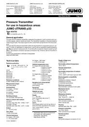
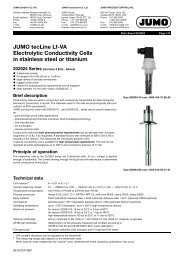
Dimensions<br />
Type 202540 / …<br />
Panel cut-out to DIN 43 700<br />
close mounting (minimum dimensions)<br />
Option<br />
Surface-mounting housing, extra code /640, IP67 protection<br />
08.04/ 00362441
JUMO GmbH & Co. KG • 36035 Fulda, Germany<br />
Data Sheet 20.2540 Page 10/10<br />
Type designation<br />
(1) Basic type<br />
202540 JUMO <strong>dTRANS</strong> <strong>Lf</strong> <strong>01</strong>,<br />
microprocessor transmitter/controller <strong>for</strong> <strong>conductivity</strong><br />
(2) Basic type extensions<br />
00 <strong>Controller</strong> off*<br />
10 Limit controller*<br />
(3) Output I<br />
000 no output<br />
310 relay, changeover contact<br />
888 process value output, freely configurable<br />
(4) Output II<br />
000 no output<br />
310 relay, changeover contact 1<br />
888 process value output, freely configurable 1<br />
(5) Supply voltage<br />
22 20 — 53 V AC/DC, 48 — 63/0 Hz<br />
23 110 — 240 V AC +10%/-15%, 48 — 63 Hz<br />
*Generally<br />
on all controllers of the<br />
202540 series, the user can<br />
freely select the following<br />
configurations:<br />
❏ <strong>Controller</strong> off<br />
❏ Limit controller<br />
❏ Pulse width controller with P,<br />
PI, PD, PID control action<br />
❏ Pulse frequency controller<br />
with P, PI, PD, PID control<br />
action<br />
❏ Modulating controller<br />
The options given in the type<br />
designation are just the factory<br />
default settings!<br />
1 If output II (4) = "310" or "888"<br />
then the interface option (6) is<br />
not possible (or the other way<br />
round)!<br />
(6) Interface<br />
00 no serial interface<br />
54 serial interface RS422/485 1<br />
64 serial interface Profibus-DP 1<br />
(7) Extra codes<br />
000 no extra codes<br />
<strong>01</strong>5 logic output 0/12 V DC,<br />
instead of standard 0/5 V DC<br />
640 surface-mounting housing <strong>for</strong> mounting on wall or DIN rail, IP67 protection<br />
(1) (2) (3) (4) 1 (5) (6) 1 (7)<br />
Order code 202540 / - , - - -<br />
Order example 202540 / 10 - 888 , 000 - 23 - 00 - 000<br />
Stock items<br />
Type<br />
Sales No.<br />
202540/00-888,000-23-00/000 20/00362661<br />
202540/10-888,000-23-00/000 20/00377231<br />
202540/00-888,000-23-00/640 20/00431436<br />
Optional accessories 1 (switchgear cabinet instrument)<br />
Designation<br />
Sales No.<br />
Bracket <strong>for</strong> C-rail 70/00375749<br />
Blind cover 96 x 48 mm 70/00069680<br />
Optional accessories 2 (wall-mounting instrument)<br />
Designation<br />
Sales No.<br />
Pole clamp, 60 mm dia. (clamping area: 50 — 70 mm dia.) 20/00437485<br />
Pole clamp, 120 mm dia. (clamping area: 100 — 120 mm dia.) 20/00437486<br />
08.04/ 00362441