dTRANS Rd 01 µP Transmitter / Controller for redox potential (ORP)
dTRANS Rd 01 µP Transmitter / Controller for redox potential (ORP)
dTRANS Rd 01 µP Transmitter / Controller for redox potential (ORP)
- No tags were found...

You also want an ePaper? Increase the reach of your titles
YUMPU automatically turns print PDFs into web optimized ePapers that Google loves.
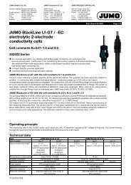
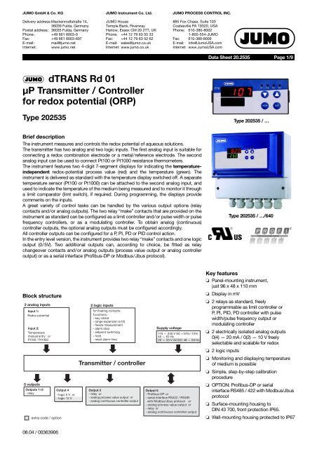
JUMO GmbH & Co. KGDelivery address:Mackenrodtstraße 14,36039 Fulda, GermanyPostal address: 36035 Fulda, GermanyPhone: +49 661 6003-0Fax: +49 661 6003-607E-mail: mail@jumo.netInternet: www.jumo.netJUMO Instrument Co. Ltd.JUMO HouseTemple Bank, RiverwayHarlow, Essex CM 20 2TT, UKPhone: +44 12 79 63 55 33Fax: +44 12 79 63 52 62E-mail: sales@jumo.co.ukInternet: www.jumo.co.ukJUMO PROCESS CONTROL INC.885 Fox Chase, Suite 103Coatesville PA 19320, USAPhone: 610-380-80021-800-554-JUMOFax: 610-380-8009E-mail: info@JumoUSA.comInternet: www.JumoUSA.comData Sheet 20.2535Page 1/9<strong>dTRANS</strong> <strong>Rd</strong> <strong>01</strong>µP <strong>Transmitter</strong> / <strong>Controller</strong><strong>for</strong> <strong>redox</strong> <strong>potential</strong> (<strong>ORP</strong>)Type 202535Type 202535 / …Brief descriptionThe instrument measures and controls the <strong>redox</strong> <strong>potential</strong> of aqueous solutions.The transmitter has two analog and two logic inputs. The first analog input is suitable <strong>for</strong>connecting a <strong>redox</strong> combination electrode or a metal/reference electrode. The secondanalog input can be used to connect Pt100 or Pt1000 resistance thermometers.The instrument features two 4-digit 7-segment displays <strong>for</strong> indicating the temperatureindependent<strong>redox</strong>-<strong>potential</strong> process value (red) and the temperature (green). Theinstrument is delivered as standard with the temperature display switched off. A separatetemperature sensor (Pt100 or Pt1000) can be attached to the second analog input, andused to indicate the temperature of the medium being measured and to monitor it througha limit comparator (limt switch), if required. During programming, the displays providecomments on the inputs.A great variety of control tasks can be handled by the various output options (relaycontacts and/or analog outputs). The two relay “make” contacts that are provided on theinstrument as standard can be configured as a limit controller and/or pulse width or pulsefrequency controllers, or as a modulating controller. To obtain analog (continuous)controller outputs, the optional analog outputs must be configured accordingly.All controller outputs can be configured <strong>for</strong> a P, PI, PD or PID control action.In the entry level version, the instrument provides two relay “make” contacts and one logicoutput (0/5V). Two additional outputs can, according to choice, be fitted as relaychangeover contacts and/or analog outputs (process value output or analog controlleroutput) or as a serial interface (Profibus-DP or Modbus/Jbus protocol).Type 202535 / …/640Block structureKey features❏ Panel-mounting instrument,just 96 x 48 x 110 mm❏ Display in mV❏ 2 relays as standard, freelyprogrammable as limit controller orP, PI, PID, PD controller with pulsewidth/pulse frequency output ormodulating controller❏ 2 electrically isolated analog outputs0(4) — 20 mA / 0(2) — 10 V freelyselectable and scalable <strong>for</strong> <strong>redox</strong>❏ 2 logic inputs❏ Monitoring and displaying temperatureof medium is possible❏ Simple, step-by-step calibrationprocedure❏ OPTION: Profibus-DP or serialinterface RS485 / 422 with Modbus/Jbusprotocol❏ Surface-mounting housing toDIN 43 700, front protection IP65.❏ Wall-mounting housing protected to IP6708.04 / 00363906
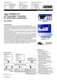
JUMO GmbH & Co. KG • 36035 Fulda, GermanyData Sheet 20.2535 Page 2/9OperationFor easy programming and operation, thecontroller parameter and configurationdata are assigned to various levels.Indications / controls(1)(7)mVK1 K2 K3 K4(2)(3)(6)°CPGMEXIT(4)(5)Code words protect the levels fromunauthorized access.Membrane keys ensure simple and userfriendlyoperation.The two LED displays show the parametersymbols and the corresponding values.Operating levelThe lower display, <strong>for</strong> example, shows thesymbol, the upper display shows thecorresponding value. Setpoints SPr1 andSPr2 can be altered by using themembrane keys.Parameter levelThe controller is adapted to the controlloop at this level. The appropriateparameters appear here, with symbol andvalue.Only those parameters will be indicatedwhich correspond to the configuration ofthe controller (configuration level).Configuration levelThis level is used to adapt the controller tothe control task, or <strong>for</strong> adaptation of theinputs and outputs.(1) Status indicators (yellow)<strong>for</strong> outputs 1 to 4(2) Increment key <strong>for</strong> altering parametersor manual operation of relay K2(3) Decrement key <strong>for</strong> altering parametersor manual operation of relay K1(4) EXIT key to leavethe levels(5) PGM key <strong>for</strong> selection of parametersand confirmation of entriesCalibration optionsThe electrode zero point of a <strong>redox</strong>combination electrode is subject tomanufacturing tolerances and variationsdepending on usage.The transmitter offers the feature of usinga step-by-step calibration procedure – the1-point calibration – to make a freshdetermination of the zero point of theelectrode by using a buffer solution or asolution with a known <strong>redox</strong> <strong>potential</strong>.The transmitter also offers the facility ofmanually entering or adjusting the zeropoint (as determined by a laboratory, <strong>for</strong>example).Additional functions of the JUMO<strong>dTRANS</strong> <strong>Rd</strong> <strong>01</strong>❏ Programmable response of theprocess value output tounderrange/overrangeOn underrange or overrange, theprocess value output can move to thefollowing operational states:-4%, 0%, 100% or 110% freelyselectableExample: Instrument is programmed to4 — 20 mA corresponding to100 — 500 mVThe instrument can be set up so that, onfalling below 100, the output signal iseither held at 4 mA (0%) or drops to3.84 mA (-4%). The 3.84 mA value can(6) 4-digit temperature display(LED, green, 8mm high)(7) 4-digit process value indication(LED, red, 13mm high)(3)+(5)(2)+(4)“CAL”: Initiating electrode calibration(single-point calibration)Initiate manual operation or holdthen be recognized as “irregular” by aconnected PLC.❏ The response of the controller relaysto “Hold” can be defined“Hold” is initiated either manually, usingthe keys, by a logic input, or by an alarmevent. The outputs of the relays K1 andK2 can move to the following(programmable) states on “Hold”:0% Relay de-energized50% output For dynamic controllers,50% of the maximumpulse width or frequencyis produced100% output Relay is energized, ormaximum pulse width /frequencyOutputacceptedThe present outputcontinues to beproduced❏ In “Manual” mode, the relays K1 andK2 are operated manually, by usingthe keys. Either key or switch operationcan be selected, by a setting at theparameter level.Key operation: The relay is switched aslong as the key is pressed (e.g. <strong>for</strong>manual dosing).Switch operation: The first key strokeswitches the relay on – the secondswitches it off again (toggle action), e.g.<strong>for</strong> emptying large tanks.08.04 / 00363906
JUMO GmbH & Co. KG • 36035 Fulda, GermanyData Sheet 20.2535 Page 3/9❏ Simulation of the analog processvalue outputIn the manual mode, the process valueoutput (0/2 — 10 V or 0/4 — 20 mA,depending on the setting) can beswitched in 10% steps from 0 — 100%.Application: “Dry-run” commissioning ofthe plant (without electrodes), faultfinding,servicing.❏ <strong>Controller</strong> output functionsOutput 1 (relay): Switching, with pulsefrequency or pulse width action / limitmonitoring / switched off. Switchingfunction can be reversed.MAX / MIN limit comparator.Output 2 (relay): Switching, with pulsefrequency or pulse width action / limitmonitoring / MAX/MIN limit comparator<strong>for</strong> temperature input / switched off.Switching function can be reversed.MAX/MIN limit comparator.Output 3, relay or analog process valueoutput: “Hold” / alarm pulse contact; alarmsteady contact / MAX/MIN limitcomparator / output of <strong>redox</strong> <strong>potential</strong>(only <strong>for</strong> analog process value output) /output of temperature process value (only<strong>for</strong> analog process value output) / analogcontroller output (only <strong>for</strong> analog processvalue output) / no function.Output 4, logic output: “Hold“ / alarmpulse contact / alarm steady contact /MAX/MIN limit comparator / no function.Output 5, relay or analog process valueoutput: “Hold” / alarm pulse contact; alarmsteady contact / MAX/MIN limitcomparator / output of <strong>redox</strong> <strong>potential</strong>(only <strong>for</strong> analog process value output) /output of temperature process value (only<strong>for</strong> analog process value output) / analogcontroller output (only <strong>for</strong> analog processvalue output) / no function.Limit comparator(limit monitor)<strong>Controller</strong> outputs 1 to 5 (depending onthe instrument version) can be assigned tolimit-monitoring functions.For each one, the direction of switching(pulled in going above, or going below alimit), pull-in and/or drop-out delay, and ahysteresis can all be defined.InterfaceThe µP transmitter/controller can beoptionally fitted with an RS422 /RS485interface. This is used <strong>for</strong> communicationwith higher-level systems and integrationinto a data network. The transmissionprotocol can be either Profibus-DP orModbus/Jbus.Technical dataInputsAnalog input 1Input resistance ≥ 10 12 ΩInsulation resistance of the referencesystem connection to ground > 10 7 Ωaccording to DIN 19 265For all the usual metal combinationelectrodes or metal/reference electrodes.Analog input 2Resistance thermometer Pt100 orPt 1000, in 2- or 3-wire circuit-50 to +250°CMeasurement display in °C (option °F)Lead compensation, analog input 2The lead resistance can be compensatedin software by a correction of the processvalue.This is not required if the resistancethermometer is connected in a 3-wirecircuit.When a resistance thermometer isconnected in a 2-wire circuit, leadcompensation can be provided by using anexternal compensation resistor.Functional description of logic inputs 1and 2The two standard logic inputs can beoperated by floating contacts (relays) froma PLC, or by switches. The followingfunctions can be selected and assigned:Key inhibit: The PLC or a key switch can beused to lock the keys on the transmitter, toprevent unauthorized entries being made.Setpoint changeover: For com<strong>for</strong>tableprocess control. As long as the logic inputis not operated, setpoint pair SPr1 andSPr2 is active. If the appropriatelyconfigured logic input is operated, then thesecond setpoint pair is activated.Freeze measurement: The indicatedmeasurement and the process valueoutput no longer change.“Hold”: This function can be used (<strong>for</strong>instance, by a supervisory PLC) to put theinstrument into the secure “Hold” state.The response of the controller to “Hold” isas previously defined.“Hold reversed”: The same function asHOLD, but when the logic input is open.Alarm stop: The alarm generation via theconfigured output is prevented, but thealarm LED (e.g. K4) continues to blink as awarning.Reset alarm time: The alarm generation viathe configured output is prevented. Thealarm delay time is set to zero, but isrestarted when the logic input becomesinactive and the start conditions are fulfilledonce more. The alarm LED (e.g. K4)continues to blink as a warning.Range expansion (x10): If only a smallportion of the measurement range is used,it may be advantageous <strong>for</strong> the transmitterto react to 0 — 10% of the process valueby producing 0 — 100% of the outputsignal.Measurement and control range-1999 to +1999 mVDeviation from characteristic≤ 0.25% per 10 °CAmbient temperature error≤ 0.15% per 10 °CTemperature display-50 to +250°C (option °F)Deviation from characteristic≤ 0.25% of measurement rangeAmbient temperature error≤ 0.1% per 10 °COutputs2 relay outputs, 1 logic output, 1 analogprocess value output or 1 additional relay,and 1 serial interface are available.1. Relay, output 1 / 2 (standard)Make contact (n.o., can also beconfigured as n.c. break contact)contact rating: 3A, 250V ACwith resistive loadcontact life:> 5x10 5 operations at rated load2. Logic output, output 40/5V R load ≥ 250Ωor0/12V R load ≥ 650Ω (option)3. Process value output, output 3 or 5(option)freely configurable:0(2) — 10V R load ≥ 500Ω or0(4) — 20mA R load ≥ 500Ωelectrically isolated from the inputs:∆U ≤ 30V AC or∆U ≤ 50V DCDeviation of output signal fromcharacteristic≤ 0.25%, ± 50 ppm per °C4. Relay, output 3 or 5 (option)(only <strong>for</strong> instruments without a processvalue output)changeover contactcontact rating: 3A, 250V ACwith resistive loadcontact life:> 5x10 5 operations at rated load5. Interface RS422 / RS485,Output 5 (option)electrically isolatedBaud rate4800/ 9600bpsProtocolModbus / Jbus orProfibus-DP08.04 / 00363906
JUMO GmbH & Co. KG • 36035 Fulda, GermanyData Sheet 20.2535 Page 4/9General controller dataA/D converterresolution > 15 bit<strong>Controller</strong> typeOutputs 1 and 2limit controller, pulse width or pulsefrequency controller, modulatingcontroller. Freely configurable and mixableK3 / K5:continuous controllerControl actionconfigurable as P, PI, PID or PD.Sampling time210msecMeasurement circuit monitoringInput 1: out-of-rangeInput 2: out-of-range, probe short-circuit,probe breakThe outputs move to a defined(configurable) status.Data backupEEPROMSupply voltage110 — 240 V AC +10%/-15%,48 — 63 Hzor20 — 53 V AC/DC, 48 — 63/0 Hz,Power consumptionapprox. 8V AElectrical connectionvia gold-plated faston connectors toDIN 46 244/A; 4.8mm x 0.8mm<strong>redox</strong> combination electrode or metalelectrode via BNC socket.Wall-mounting housing(extra code /640)via screw terminals(wire cross-section up to 2.5 mm 2 )6 cable glands (1 x M16, , 5 x M20)Permissibleambient temperature0 to +50°CPermissibleambient temperature limits-10 to +55°CPermissible storage temperature-40 to +70°CClimatic conditionsrel. humidity ≤ 75%, no condensationEnclosure protectionto EN 60 529Instrument <strong>for</strong> switchgear cabinetfron IP65 / rear IP20Wall-mounting instrumentIP67Electrical safetyto EN 61 <strong>01</strong>0clearance and creepage distances <strong>for</strong>- overvoltage category II- pollution degree 2Electromagnetic compatibilityto EN 61 326interference emission: Class Binterference immunity: to industrialrequirementsHousingInstrument <strong>for</strong> switchgear cabinet(basic version)panel-mounting housing in conductiveplastic to DIN 43 700, base material ABSwith plug-in controller module.Wall-mounting housing(extra code /640)base material PCOperating positionunrestrictedWeightInstrument <strong>for</strong> switchgear cabinet(basic version)approx. 320gWall-mounting housing(extra code /640)approx. 1400 gStandard accessories– 2 mounting brackets– 1 seal (housing/panel)– 1 Operating Manual B 20.2535.0.1OptionWall-mounting housingextra code /640Housing with door at frontType 2 FGE-150-2/185On request, the JUMO <strong>dTRANS</strong> <strong>Rd</strong> <strong>01</strong> canalso be supplied built into a surfacemountinghousing. The housing is suitable<strong>for</strong> wall-mounting or <strong>for</strong> mounting on a 35 x7.5 mm DIN rail to EN 50 022.The housing is sturdy and provides IP67protection <strong>for</strong> the built-in instrument and isfitted with six cable glands. Unused cableglands can be tightly sealed using the blindgrommets that are included in the delivery.The electrical connection is made viascrew terminals (wire cross-section up to2.5 mm 2 ).Standard accessories– 2 mounting brackets (not with extracode /640 (wall-mounting housing))– 1 BNC connector (not with extra code/640 (wall-mounting housing))– 1 seal <strong>for</strong> panel mounting (not withextra code /640 (wall-mountinghousing))– sundry items <strong>for</strong> wall-mounting (onlywith extra code /640 (wall-mountinghousing))– sundry items <strong>for</strong> DIN rail mounting (onlywith extra code /640 (wall-mountinghousing))– 1 Operating Manual B 20.2535.0.1Optional accessoryInterface Description B 20.2530.208.04 / 00363906
JUMO GmbH & Co. KG• 36035 Fulda, GermanyData Sheet 20.2535 Page 5/9ParametersParameter Display Value range CommentAlarm tolerance AL1 0000 — 9999 mVThe alarm is only generated when the level(setpoint + alarm tolerance) has beenpassed, and the alarm delay time haselapsed (only effective <strong>for</strong> pulse width / pulsefrequency controllers. It is internally fixed at 0<strong>for</strong> limit controllers).Alarm delay AL2 0 — 6000 secDelay time be<strong>for</strong>e the alarm contact isactivatedProportional band 1 Pb1 1 — 9999 mVProportional band 2 Pb2 1 — 9999 mVInfluences the P action of the controllerDerivative time 1dt1Influences the D action of the controllerDerivative time 2dt2If dt = 0, the controller has no D action.0 — 9999 secReset time 1 rt1 Influences the I action of the controllerReset time 2rt2If rt = 0, the controller has no I action.Minimum ON time 1(<strong>for</strong> limit controller orpulse width controller)orminimum pulse width 1(<strong>for</strong> pulse frequency controller)Minimum ON time 2(<strong>for</strong> limit controller orpulse width controller)orminimum pulse width 2(<strong>for</strong> pulse frequency controller)Switching differential 1Switching differential 2Switching differential 3Switching differential 4Switching differential 5Pull-in delay 1Pull-in delay 2Pull-in delay 3Pull-in delay 4Pull-in delay 5Drop-out delay 1tr1tr2HYS1HYS2HYS3HYS4HYS5Ond1Ond2Ond3Ond4Ond5Ofd10.2 — 999.9 sec0.2 — 999.9 sec1 — 9999 mVDetermined by the technical data of thedosing device (solenoid valve, dosing pump)Defines the switch-off point <strong>for</strong> the controlcontacts0.0 — 999.9 sec Delay time be<strong>for</strong>e the contact is activatedDrop-out delay 2Ofd2Drop-out delay 3Ofd3 0.2 — 999.9 secDelay time until the contact moves back tothe initial positionDrop-out delay 4Ofd4Drop-out delay 5Ofd5Pulse frequency 1Fr1Maximum frequency of pulses (operating a0 — 150 pulse/minPulse frequency 2Fr2dosing pump, <strong>for</strong> instance)Pulse period 1Cy1Pulse period 2Cy22.0 — 999.9 sec The period in which a pulse is modulatedOutput level limit, output 1 Y1 0 — 100% The maximum output level <strong>for</strong> a pulse width /Output level limit, output 2 Y2 0 — 100%pulse frequency controllerActuator time tt 15 — 3000 sec For modulating controller08.04 / 00363906
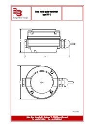
JUMO GmbH & Co. KG• 36035 Fulda, GermanyData Sheet 20.2535 Page 6/9Connection diagramRear view withfaston connectorsWall-mounting housing(extra code /640)with terminal stripOutputs K Terminal assignments SymbolRelay 1(K1)Status indicationLED K11 2322commonmake23 22PSRelay 2(K2)Status indicationLED K22 2120commonmake21 20PSRelay 3(K3)Status indicationLED K33 161514breakcommonmake16 15 14PÖ Sor1514–+14 15analog process value output(electrically isolated)+ -Logic output 1(K4)Status indicationLED K44 1917–+17 19+ -Relay 4(K5)no status indication5 321breakcommonmake3 2 1PÖ Sor21–+1 2analog process value output(electrically isolated)+ -08.04 / 00363906
JUMO GmbH & Co. KG • 36035 Fulda, GermanyData Sheet 20.2535 Page 7/9Inputs Terminal assignments SymbolRedox combination electrode with switchgear cabinet instrument:BNC socketwith wall-mounting housing (extra code /640):screw terminal 6: reference system (braiding)screw terminal 7: metal electrode (inner conductor)Metal electrodewith separate reference systemwith switchgear cabinet instrument:BNC socketwith wall-mounting housing (extra code /640):screw terminal 6: braidingscrew terminal 7: metal electrode (inner conductor)Reference electrode 8 reference system (inner conductor)Resistance thermometerin 3-wire circuit91<strong>01</strong>19 11 10ϑResistance thermometerin 2-wire circuit91<strong>01</strong>1Serial interface RS422(option)Serial interface RS485(option)RxD 54TxD 21RxD +RxD –TxD +TxD –GND 3 GND+-21GND 3 GNDTxD/RxD +TxD/RxD –Receive dataTransmit dataReceive data / transmit data5 4 2 1 32 1 3Serial interfaceProfibus-DP(option)Logic input 1 1319VP 4 supply voltage positive, (P5V)RxD/TxD-P 2 receive/transmit data positive,B conductorRxD/TxD-N 1 receive/transmit data negative,A conductorDGND 3 GND2 1 3 413 19Logic input 2 121912 19Supply voltagesee nameplateAC/DCAC:L1NTEphase/lineneutraltechnical earthDC:L +L –L1 NL+ L-TE08.04 / 00363906
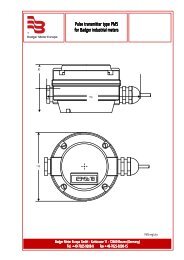
JUMO GmbH & Co. KG • 36035 Fulda, GermanyData Sheet 20.2535 Page 8/9DimensionsType 202535/...Panel cut-out to DIN 43 700Close mounting (minimum dimensions)OptionSurface-mounting housing, extra code /640, Protection IP6708.04 / 00363906
JUMO GmbH & Co. KG • 36035 Fulda, GermanyData Sheet 20.2535 Page 9/9Type designation(1) Basic type202535 JUMO <strong>dTRANS</strong> <strong>Rd</strong> <strong>01</strong>,µP transmitter / controller <strong>for</strong> <strong>redox</strong> <strong>potential</strong> (<strong>ORP</strong>)(2) Basic type extensions00 <strong>Controller</strong> off*10 Limit controller*(3) Output I000 no output310 relay, changeover contact888 process value output, freely configurable(4) Output II000 no output310 relay, changeover contact 1888 process value output, freely configurable 1(5) Supply voltage22 20 — 53 V AC/DC, 48 — 63/0 Hz23 110 — 240 V AC +10%/-15%, 48 — 63 Hz*Generallyon all controllers of the202535 series, the user canfreely select the followingconfigurations:❏ <strong>Controller</strong> off❏ Limit controller❏ Pulse width controller with P,PI, PD, PID control action❏ Pulse frequency controllerwith P, PI, PD, PID controlaction❏ Modulating controllerThe options given in the typedesignation are just the factorydefault settings!1 If output II (4) = "310" or "888"then the interface option (6) isnot possible (or the other wayround)!(6) Interface00 no serial interface54 serial interface RS422/485 164 serial interface Profibus-DP 1(7) Extra codes000 no extra codes<strong>01</strong>5 logic output 0/12 V DC,instead of standard 0/5 V DC640 surface-mounting housing <strong>for</strong> mounting on wall or DIN rail, IP67 protection(1) (2) (3) (4) 1 (5) (6) 1 (7)Order code 202535 / - , - - -Order example 202535 / 10 - 888 , 000 - 23 - 00 - 000Stock itemsTypeSales No.202535/00-888,000-23-00/000 20/00377253202535/10-888,000-23-00/000 20/00377254Optional accessories 1 (switchgear cabinet instrument)DesignationSales No.Bracket <strong>for</strong> C-rail 70/00375749Blind cover 96 x 48 mm 70/00069680Optional accessories 2 (wall-mounting instrument)DesignationSales No.Pole clamp, 60 mm dia. (clamping area: 50 — 70 mm dia.) 20/00437485Pole clamp, 120 mm dia. (clamping area: 100 — 120 mm dia.) 20/0043748608.04 / 00363906