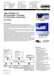
JUMO GmbH & Co. KG • 36035 Fulda, GermanyData Sheet 20.2535 Page 2/9OperationFor easy programming and operation, thecontroller parameter and configurationdata are assigned to various levels.Indications / controls(1)(7)mVK1 K2 K3 K4(2)(3)(6)°CPGMEXIT(4)(5)Code words protect the levels fromunauthorized access.Membrane keys ensure simple and userfriendlyoperation.The two LED displays show the parametersymbols and the corresponding values.Operating levelThe lower display, <strong>for</strong> example, shows thesymbol, the upper display shows thecorresponding value. Setpoints SPr1 andSPr2 can be altered by using themembrane keys.Parameter levelThe controller is adapted to the controlloop at this level. The appropriateparameters appear here, with symbol andvalue.Only those parameters will be indicatedwhich correspond to the configuration ofthe controller (configuration level).Configuration levelThis level is used to adapt the controller tothe control task, or <strong>for</strong> adaptation of theinputs and outputs.(1) Status indicators (yellow)<strong>for</strong> outputs 1 to 4(2) Increment key <strong>for</strong> altering parametersor manual operation of relay K2(3) Decrement key <strong>for</strong> altering parametersor manual operation of relay K1(4) EXIT key to leavethe levels(5) PGM key <strong>for</strong> selection of parametersand confirmation of entriesCalibration optionsThe electrode zero point of a <strong>redox</strong>combination electrode is subject tomanufacturing tolerances and variationsdepending on usage.The transmitter offers the feature of usinga step-by-step calibration procedure – the1-point calibration – to make a freshdetermination of the zero point of theelectrode by using a buffer solution or asolution with a known <strong>redox</strong> <strong>potential</strong>.The transmitter also offers the facility ofmanually entering or adjusting the zeropoint (as determined by a laboratory, <strong>for</strong>example).Additional functions of the JUMO<strong>dTRANS</strong> <strong>Rd</strong> <strong>01</strong>❏ Programmable response of theprocess value output tounderrange/overrangeOn underrange or overrange, theprocess value output can move to thefollowing operational states:-4%, 0%, 100% or 110% freelyselectableExample: Instrument is programmed to4 — 20 mA corresponding to100 — 500 mVThe instrument can be set up so that, onfalling below 100, the output signal iseither held at 4 mA (0%) or drops to3.84 mA (-4%). The 3.84 mA value can(6) 4-digit temperature display(LED, green, 8mm high)(7) 4-digit process value indication(LED, red, 13mm high)(3)+(5)(2)+(4)“CAL”: Initiating electrode calibration(single-point calibration)Initiate manual operation or holdthen be recognized as “irregular” by aconnected PLC.❏ The response of the controller relaysto “Hold” can be defined“Hold” is initiated either manually, usingthe keys, by a logic input, or by an alarmevent. The outputs of the relays K1 andK2 can move to the following(programmable) states on “Hold”:0% Relay de-energized50% output For dynamic controllers,50% of the maximumpulse width or frequencyis produced100% output Relay is energized, ormaximum pulse width /frequencyOutputacceptedThe present outputcontinues to beproduced❏ In “Manual” mode, the relays K1 andK2 are operated manually, by usingthe keys. Either key or switch operationcan be selected, by a setting at theparameter level.Key operation: The relay is switched aslong as the key is pressed (e.g. <strong>for</strong>manual dosing).Switch operation: The first key strokeswitches the relay on – the secondswitches it off again (toggle action), e.g.<strong>for</strong> emptying large tanks.08.04 / 00363906
JUMO GmbH & Co. KG • 36035 Fulda, GermanyData Sheet 20.2535 Page 3/9❏ Simulation of the analog processvalue outputIn the manual mode, the process valueoutput (0/2 — 10 V or 0/4 — 20 mA,depending on the setting) can beswitched in 10% steps from 0 — 100%.Application: “Dry-run” commissioning ofthe plant (without electrodes), faultfinding,servicing.❏ <strong>Controller</strong> output functionsOutput 1 (relay): Switching, with pulsefrequency or pulse width action / limitmonitoring / switched off. Switchingfunction can be reversed.MAX / MIN limit comparator.Output 2 (relay): Switching, with pulsefrequency or pulse width action / limitmonitoring / MAX/MIN limit comparator<strong>for</strong> temperature input / switched off.Switching function can be reversed.MAX/MIN limit comparator.Output 3, relay or analog process valueoutput: “Hold” / alarm pulse contact; alarmsteady contact / MAX/MIN limitcomparator / output of <strong>redox</strong> <strong>potential</strong>(only <strong>for</strong> analog process value output) /output of temperature process value (only<strong>for</strong> analog process value output) / analogcontroller output (only <strong>for</strong> analog processvalue output) / no function.Output 4, logic output: “Hold“ / alarmpulse contact / alarm steady contact /MAX/MIN limit comparator / no function.Output 5, relay or analog process valueoutput: “Hold” / alarm pulse contact; alarmsteady contact / MAX/MIN limitcomparator / output of <strong>redox</strong> <strong>potential</strong>(only <strong>for</strong> analog process value output) /output of temperature process value (only<strong>for</strong> analog process value output) / analogcontroller output (only <strong>for</strong> analog processvalue output) / no function.Limit comparator(limit monitor)<strong>Controller</strong> outputs 1 to 5 (depending onthe instrument version) can be assigned tolimit-monitoring functions.For each one, the direction of switching(pulled in going above, or going below alimit), pull-in and/or drop-out delay, and ahysteresis can all be defined.InterfaceThe µP transmitter/controller can beoptionally fitted with an RS422 /RS485interface. This is used <strong>for</strong> communicationwith higher-level systems and integrationinto a data network. The transmissionprotocol can be either Profibus-DP orModbus/Jbus.Technical dataInputsAnalog input 1Input resistance ≥ 10 12 ΩInsulation resistance of the referencesystem connection to ground > 10 7 Ωaccording to DIN 19 265For all the usual metal combinationelectrodes or metal/reference electrodes.Analog input 2Resistance thermometer Pt100 orPt 1000, in 2- or 3-wire circuit-50 to +250°CMeasurement display in °C (option °F)Lead compensation, analog input 2The lead resistance can be compensatedin software by a correction of the processvalue.This is not required if the resistancethermometer is connected in a 3-wirecircuit.When a resistance thermometer isconnected in a 2-wire circuit, leadcompensation can be provided by using anexternal compensation resistor.Functional description of logic inputs 1and 2The two standard logic inputs can beoperated by floating contacts (relays) froma PLC, or by switches. The followingfunctions can be selected and assigned:Key inhibit: The PLC or a key switch can beused to lock the keys on the transmitter, toprevent unauthorized entries being made.Setpoint changeover: For com<strong>for</strong>tableprocess control. As long as the logic inputis not operated, setpoint pair SPr1 andSPr2 is active. If the appropriatelyconfigured logic input is operated, then thesecond setpoint pair is activated.Freeze measurement: The indicatedmeasurement and the process valueoutput no longer change.“Hold”: This function can be used (<strong>for</strong>instance, by a supervisory PLC) to put theinstrument into the secure “Hold” state.The response of the controller to “Hold” isas previously defined.“Hold reversed”: The same function asHOLD, but when the logic input is open.Alarm stop: The alarm generation via theconfigured output is prevented, but thealarm LED (e.g. K4) continues to blink as awarning.Reset alarm time: The alarm generation viathe configured output is prevented. Thealarm delay time is set to zero, but isrestarted when the logic input becomesinactive and the start conditions are fulfilledonce more. The alarm LED (e.g. K4)continues to blink as a warning.Range expansion (x10): If only a smallportion of the measurement range is used,it may be advantageous <strong>for</strong> the transmitterto react to 0 — 10% of the process valueby producing 0 — 100% of the outputsignal.Measurement and control range-1999 to +1999 mVDeviation from characteristic≤ 0.25% per 10 °CAmbient temperature error≤ 0.15% per 10 °CTemperature display-50 to +250°C (option °F)Deviation from characteristic≤ 0.25% of measurement rangeAmbient temperature error≤ 0.1% per 10 °COutputs2 relay outputs, 1 logic output, 1 analogprocess value output or 1 additional relay,and 1 serial interface are available.1. Relay, output 1 / 2 (standard)Make contact (n.o., can also beconfigured as n.c. break contact)contact rating: 3A, 250V ACwith resistive loadcontact life:> 5x10 5 operations at rated load2. Logic output, output 40/5V R load ≥ 250Ωor0/12V R load ≥ 650Ω (option)3. Process value output, output 3 or 5(option)freely configurable:0(2) — 10V R load ≥ 500Ω or0(4) — 20mA R load ≥ 500Ωelectrically isolated from the inputs:∆U ≤ 30V AC or∆U ≤ 50V DCDeviation of output signal fromcharacteristic≤ 0.25%, ± 50 ppm per °C4. Relay, output 3 or 5 (option)(only <strong>for</strong> instruments without a processvalue output)changeover contactcontact rating: 3A, 250V ACwith resistive loadcontact life:> 5x10 5 operations at rated load5. Interface RS422 / RS485,Output 5 (option)electrically isolatedBaud rate4800/ 9600bpsProtocolModbus / Jbus orProfibus-DP08.04 / 00363906