MODBUS RTU (zero-based addressing)
MODBUS RTU (zero-based addressing)
MODBUS RTU (zero-based addressing)
- No tags were found...

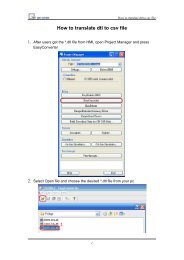
Create successful ePaper yourself
Turn your PDF publications into a flip-book with our unique Google optimized e-Paper software.
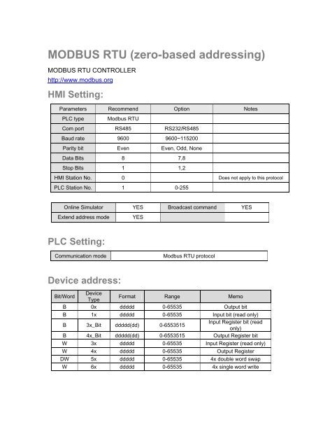
<strong>MODBUS</strong> <strong>RTU</strong> (<strong>zero</strong>-<strong>based</strong> <strong>addressing</strong>)<br />
<strong>MODBUS</strong> <strong>RTU</strong> CONTROLLER<br />
http://www.modbus.org<br />
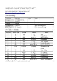
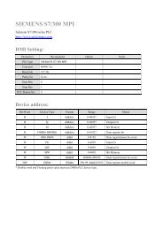
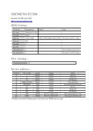
HMI Setting:<br />
Parameters Recommend Option Notes<br />
PLC type Modbus <strong>RTU</strong><br />
Com port RS485 RS232/RS485<br />
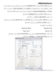
Baud rate 9600 9600~115200<br />
Parity bit Even Even, Odd, None<br />
Data Bits 8 7,8<br />
Stop Bits 1 1,2<br />
HMI Station No. 0 Does not apply to this protocol<br />
PLC Station No. 1 0-255<br />
Online Simulator YES Broadcast command YES<br />
Extend address mode<br />
YES<br />
PLC Setting:<br />
Communication mode<br />
Modbus <strong>RTU</strong> protocol<br />
Device address:<br />
Bit/Word<br />
Device<br />
Type<br />
Format Range Memo<br />
B 0x ddddd 0-65535 Output bit<br />
B 1x ddddd 0-65535 Input bit (read only)<br />
B 3x_Bit ddddd(dd) 0-6553515<br />
Input Register bit (read<br />
only)<br />
B 4x_Bit ddddd(dd) 0-6553515 Output Register bit<br />
W 3x ddddd 0-65535 Input Register (read only)<br />
W 4x ddddd 0-65535 Output Register<br />
DW 5x ddddd 0-65535 4x double word swap<br />
W 6x ddddd 0-65535 4x single word write
NOTE:<br />
Address type “5x” are mapping to Hold Reg. The communication protocol of 5x<br />
almost same as “4x” except “5x”making double word swap.<br />
If 4x have following information<br />
Address 1 2 3 4 5 6 ...<br />
Data in word 0x1 0x2 0x3 0x4 0x5 0x6<br />
Data 0x20001 0x40003 0x60005<br />
For 5x, it become<br />
Address 1 2 3 4 5 6 ...<br />
Data in word 0x2 0x1 0x4 0x3 0x6 0x5<br />
Data 0x10002 0x30004 0x50006<br />
Modbus <strong>RTU</strong> function code:<br />
0x 0x01 Read coil 0x05 write single coil<br />
1x 0x02 Read discrete input N/A for write operation<br />
3x 0x04 Read input register N/A for write operation<br />
4x 0x03 Read holding register 0x10 write multiple register<br />
5x 0x03 Read holding register 0x10 write multiple register<br />
(Note: reverse word order in double word format)<br />
3xbit is equivalent to 3x<br />
4xbit is equivalent to 4x<br />
6x 0x03 Read holding register 0x06 write single register<br />
(Note: use 6x device is limited to device of one word only)<br />
Wiring diagram:<br />
<strong>MODBUS</strong> RS232 PORT<br />
MT8000 RS-232<br />
9P D-SUB<br />
COM1 COM2 COM3<br />
Modbus <strong>RTU</strong><br />
Controller RS232<br />
Port<br />
3 TX 4 TX 7 TX RXD<br />
2 RX 6 RX 8 RX TXD<br />
5 GND 5 GND 5 GND GND<br />
RTS<br />
CTS
<strong>MODBUS</strong> RS422/485 PORT<br />
MT8000<br />
COM1 RS-485 4w<br />
Modbus <strong>RTU</strong> Controller<br />
RS422 Port<br />
1 RX- TX-<br />
2 RX+ TX+<br />
3 TX- RX-<br />
4 TX+ RX+<br />
5 GND GND<br />
MT8000 RS-485 2Wire<br />
9P D-SUB<br />
Modbus <strong>RTU</strong><br />
Controller RS485<br />
COM1<br />
COM3<br />
1 RX- 6 Data- D-<br />
2 RX+ 9 Data+ D+<br />
5 GND 5 GND GND<br />
Note: <strong>MODBUS</strong> <strong>RTU</strong> (adjustable) usage<br />
Users can decide the address range via setting value on Parameter 1. For<br />
example, when users set 5 to Parameter 1, the address range become<br />
5~65535.