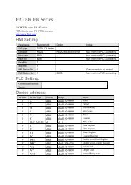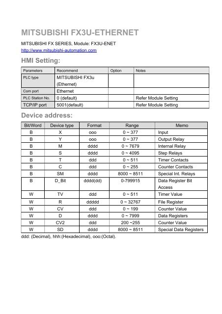
mitsubishi_fx3u-enet
mitsubishi_fx3u-enet
mitsubishi_fx3u-enet
- No tags were found...

You also want an ePaper? Increase the reach of your titles
YUMPU automatically turns print PDFs into web optimized ePapers that Google loves.
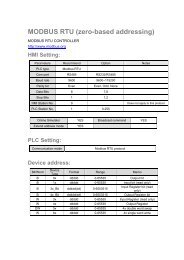
Wiring diagram:Ethernet:MT8000Ethernet RJ45Wire colorEthernet Hub orSwitch RJ451 TX+ White/Orange 1 RX+2 TX- Orange 2 RX-3 RX+ White/Green 3 TX+4 BD4+ Blue 4 BD4+5 BD4- White/Blue 5 BD4-6 RX- Green 6 TX-7 BD3+ White/Brown 7 BD3+8 BD3- Brown 8 BD3-Ethernet: Direct connect (crossover cable)MT8000Ethernet RJ45Wire colorModbus TCP DeviceRJ451 TX+ White/Orange 3 RX+2 TX- Orange 6 RX-3 RX+ White/Green 1 TX+4 BD4+ Blue 4 BD4+5 BD4- White/Blue 5 BD4-6 RX- Green 2 TX-7 BD3+ White/Brown 7 BD3+8 BD3- Brown 8 BD3-
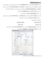
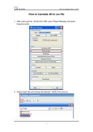
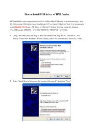
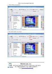
Fx3u-ENET module setting:Before using Ethernet module, using GX Developer / FX Configurator-EN to set theEthernet module, the FX3u-ENET module settings as below steps.1. Open GX Developer, select “Read from PLC” in Online list.2. Select “FXCPU” in PLC series.3. Users have to connect PLC via series port for setting IP address at first time.
4. After finishing the PLC settings, select Tools/FX special function utility/FXConfigurator-EN5. Select “Module 0” in Ethernet Module settings.
( If more than one module, please setting modules step by step)6. In Ethernet operational settings, select the related parameters and IP address and thenpress ”End” to finish the settings.7. In Ethernet open settings, press “End” after setting the below parameters.
(The first Protocol means using GX Developer to communicate with module, The max.“Fixed buffer communication preocedure” is 4 units.)8. After setting the parameters to PLC, restart for using Ethernet communication.