Electronic Wiper Control - Exalto
Electronic Wiper Control - Exalto
Electronic Wiper Control - Exalto
- No tags were found...

Create successful ePaper yourself
Turn your PDF publications into a flip-book with our unique Google optimized e-Paper software.
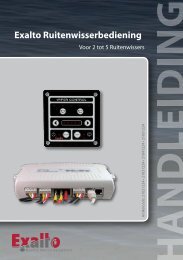
<strong>Electronic</strong> <strong>Wiper</strong> <strong>Control</strong><br />
For two <strong>Exalto</strong> H.D. <strong>Wiper</strong>s<br />
Cat. no. one continuous speed: 210212/1 (12V) • 210224/2 (24V)<br />
Quality Marine Equipment
Contents<br />
1 General ............................................................... 4<br />
1.1 Functions ......................................................... 4<br />
1.2 Description ....................................................... 5<br />
1.3 Power supply . . . . . . . . . . . . . . . . . . . . . . . . . . . . . . . . . . . . . . . . . . . . . . . . . . . . . 5<br />
1.4 Technical specifications. ........................................... 5<br />
1.5 Default settings ................................................... 5<br />
1.6 LED indicator bar ................................................. 6<br />
1.7 Individual wiper buttons . . . . . . . . . . . . . . . . . . . . . . . . . . . . . . . . . . . . . . . . . . 6<br />
1.8 Declaration of conformity ......................................... 6<br />
2 Installation ............................................................ 7<br />
2.1 Dimensions touch pad ............................................ 7<br />
2.2 Installation of the touch pad ...................................... 7<br />
2.3 Dimensions junction box .......................................... 8<br />
2.4 Installation of the junction box .................................... 8<br />
3 Electric connections ................................................... 9<br />
3.1 General lay out ................................................... 9<br />
3.2 Wiring codes ..................................................... 9<br />
3.3 <strong>Wiper</strong> connections ............................................... 10<br />
3.4 Fuse sizes ........................................................ 11<br />
3.5 Cable sizes ....................................................... 12<br />
4 Operation ............................................................ 12<br />
4.1 ON/OFF switching ............................................... 12<br />
4.2 Choice of wipers ................................................. 12<br />
4.3 Continuous mode ................................................ 12<br />
4.4 Intermittent mode ............................................... 12<br />
4.5 Wipe/wash program ............................................. 13<br />
4.6 Synchronised operation .......................................... 14<br />
4.7 Self parking ...................................................... 14
1 General<br />
1.1 Functions<br />
Brief explanation of buttons and LED’s. Please, check chapter 4 for complete<br />
operating instructions.<br />
3<br />
WIPER CONTROL<br />
2<br />
5<br />
6<br />
4<br />
1 7<br />
E xalto<br />
WASH<br />
Pos. Function<br />
1 Main ON/OFF switch and LED<br />
Turns main power to the system on and off<br />
2 Individual wiper ON/OFF buttons<br />
Turns each wiper ON or OFF<br />
3 Individual wiper LED<br />
Lights when appropriate wiper is operating<br />
4 Intermittent button<br />
Increases the frequency of wiping in the intermittent mode<br />
5 Intermittent button<br />
Decreases the frequency of wiping in the intermittent mode<br />
6 LED indicator bar<br />
Used to indicate continuous mode or the intermittent setting<br />
7 Wipe/wash button<br />
Activates the wipe/wash program<br />
4
1.2 Description<br />
This electronic wiper control consists of a touch pad with 4 metres (13’)<br />
connection cable and a separate junction box. The operation is based on a<br />
microprocessor and controls up to two wipers. Each wiper can be switched ON<br />
and OFF individually, but they can also run together.<br />
This wiper control offers:<br />
• one continuous speed;<br />
• four intermittent speeds;<br />
• self parking;<br />
• wipe/wash program.<br />
This control includes visual indications when it is ON, and for the continuous<br />
and intermittent modes.<br />
1.3 Power supply<br />
This wiper control is available in two versions to operate under a power supply<br />
of 12V or 24V DC. Check the power supply of the unit supplied, before<br />
connecting it to the ships electric system.<br />
1.4 Technical specifications<br />
Power supply:<br />
8 – 15V (12V) and 16 – 30V (24V)<br />
Stand-by power consumption: less than 4W<br />
Protections:<br />
reversed polarity<br />
Working temperature: -10°C to +60°C<br />
Storage temperature:<br />
-30°C to +70°C<br />
Inputs:<br />
1 – 2 parking signals<br />
Outputs:<br />
1 – 2 wiper contacts<br />
pump/solenoid<br />
Max. amperage draw:<br />
12V wipers: 8A<br />
24V wipers: 4A<br />
pump/solenoid: 1A<br />
1.5 Default settings<br />
When the wipers are switched ON, an internal test will be carried out. All LED’s<br />
in the LED indicator bar will lit for a few seconds. All wipers will start in the six<br />
second intermittent mode, and LED’s A and B will be lit.<br />
5
1.6 LED indicator bar<br />
The LED’s on the indicator bar (pos. 6) indicate the following settings:<br />
A<br />
B<br />
C D<br />
E<br />
Intermittent modes:<br />
Maximum delay (12 sec):<br />
Medium delay (6 sec):<br />
Medium delay (4 sec):<br />
Minimum delay (2 sec):<br />
Continuous mode:<br />
Low speed:<br />
Illuminated LED: A<br />
Illuminated LED’s: A + B<br />
Illuminated LED’s: A + B + C<br />
Illuminated LED’s: A + B + C + D<br />
Illuminated LED’s: A + B + C + D + E<br />
1.7 Individual wiper buttons<br />
When pressing the individual wiper buttons (pos. 2), each wiper can be<br />
switched ON and OFF individually. Please refer to paragraph 3.3 for the wiper<br />
connections<br />
<strong>Wiper</strong> Wisser 1 <strong>Wiper</strong> Wisser 23<br />
1.8 Declaration of conformity<br />
This wiper control complies with the European requirements for<br />
electromagnetic compatibility, as required from 89/366/EEC, 73/33/EEC and<br />
EN60945 directives.<br />
6
2 Installation<br />
2.1 Dimensions touch pad<br />
75<br />
98<br />
Ø3,5<br />
35<br />
26 14<br />
85<br />
78<br />
100<br />
79<br />
82,5<br />
Dimensions in mm<br />
2.2 Installation of touch pad<br />
The touch pad is to be fitted at a location that is within reach of the helmsman,<br />
allowing ease of operation. Make sure that sufficient room is available for the<br />
cables and the connectors. The required mounting hole for the touch pad is<br />
79 x 80 mm. There should be at least 75 mm (3”) space available under the<br />
front of the touch pad for the connection cable and plug.<br />
The touch pad has four recessed mounting holes of 3,5 mm in diameter. They<br />
allows easy and quickly fitting using stainless steel screws or the bolts and nuts<br />
supplied.<br />
7
2.3 Dimensions junction box<br />
73<br />
35<br />
113<br />
75<br />
115<br />
155<br />
Dimensions in mm.<br />
Mounting holes<br />
2.4 Installation of junction box<br />
The connection cable of 4 m (13”) length allows installation of the junction box<br />
at such a distance, that the ‘clicking’ of the relays will not disturb the helmsman.<br />
Should the junction box need to be installed at a larger distance, extension<br />
cables are available in 3 m and 6 m. Maximum distance between the touch pad<br />
and the junction box is 10 m.<br />
The junction box must be mounted in a horizontal position and in a vibration<br />
free location. The junction box contains relays that will not reset properly if<br />
mounted otherwise.<br />
The junction box has four mounting locations (holes not yet drilled). Only two<br />
locations can be used, as the other two are blocked by the circuit board. The<br />
box needs to be opened for drilling the two holes from the inside. The box can<br />
then easily and quickly be fitted using stainless steel screws or bolts and nuts.<br />
8
3 Electric connections<br />
3.1 General lay out<br />
WIPER CONTROL<br />
WIPER<br />
CONTR<br />
OL<br />
W 11 W 2 W 32<br />
ON/OFF WASH<br />
W<br />
<strong>Exalto</strong><br />
S<br />
A<br />
E<br />
S<br />
H<br />
x<br />
p<br />
a<br />
lt r<br />
o<br />
o<br />
e<br />
i<br />
e<br />
n<br />
3.2 Wiring codes<br />
4m (13’)<br />
15 12 9 6 3<br />
14 11 8 5 2<br />
13 10 7 4 1<br />
Code and function<br />
1: Battery + 9: Not in use<br />
2: Not in use 10: High speed connection<br />
3: Not in use 11: <strong>Wiper</strong> 2 relay<br />
4: Negative (-) 12: <strong>Wiper</strong> 2 self-park<br />
5: Not in use 13: Washer pump output<br />
6: Not in use 14: <strong>Wiper</strong> 1 relay<br />
7: Dynamic park relay 15: <strong>Wiper</strong> 1 self-park<br />
8: Not in use<br />
9
3.3 <strong>Wiper</strong> connections<br />
W 1 W 2 W 3<br />
W 1 W 2<br />
<strong>Wiper</strong> 2<br />
<strong>Wiper</strong> 1<br />
<strong>Wiper</strong> 32<br />
Color code and<br />
connection of wiring<br />
coming from the<br />
junction box is:<br />
* Red is to be<br />
connected to the Self<br />
Park (53a) motor wire<br />
* Black is to be<br />
connected to the<br />
Negative (31b) and<br />
Common Leg (53e) of<br />
the motor wire<br />
* Yellow is to be<br />
connected to the Low<br />
Speed (53) of the<br />
motor wire<br />
* White is to be<br />
connected to the High<br />
Speed (53b) of the<br />
motor wire<br />
Pump / solenoid Blue<br />
Battery -<br />
Black<br />
Battery + Red<br />
Battery<br />
12V / 24V<br />
Red<br />
Black<br />
Yellow<br />
White<br />
53a = Self park<br />
53e = Common leg<br />
31b = Negative<br />
53 = Low speed<br />
53b = Not High Used speed<br />
To wiper motor<br />
Always refer to the users manual as<br />
supplied with the <strong>Exalto</strong> wipers, before<br />
connecting <strong>Exalto</strong> wipers to the control<br />
panels!<br />
10
3.4 Fuse sizes<br />
The power supply line on the circuit board in the junction box has an<br />
integrated fuse of 2A. Each wiper outlet has an integrated fuse of 10A for 12V<br />
systems and 6A for 24V systems, located in the junction box.<br />
3.5 Cable sizes<br />
Use new cables that are undamaged and of sufficient diameter. This to prevent<br />
too much resistance for the required electrical current.<br />
Recommended cable sizes:<br />
Amperage Max. length Min. diameter<br />
0.1 – 2.5 10 m (33“) 2.5 mm² (14 gauge)<br />
2.6 – 4.0 10 m (33“) 4.0 mm² (12 gauge)<br />
4.1 – 8.0 10 m (33”) 6.0 mm² (10 gauge)<br />
11
4 Operation<br />
4.1 ON/OFF switching<br />
With the ON/OFF button (pos. 1) the wipers can be switched on. When pressing<br />
this button once, an internal test is carried out. Both wipers will start in the<br />
default setting and the LED’s above the individual wiper buttons (pos. 3) will<br />
illuminate. The LED next to the ON/OFF button (pos. 1) will stay illuminated as<br />
long as the panel is ON. When this button is pressed again, all wipers will park<br />
and stop.<br />
4.2 Choice of wipers<br />
When pressing one of the wiper buttons on pos. 2 each wiper can be switched<br />
ON and OFF individually. The LED’s above these buttons (pos. 3) indicate which<br />
wipers are activated. Switching ON a wiper when the other is already operating<br />
may cause a short delay of the other wiper. This is to synchronise the operation.<br />
4.3 Continuous mode<br />
To activate the continuous mode, press the button on pos. 4 until LED’s A, B, C,<br />
D and E on the LED indicator bar (pos. 6) are illuminated. Both wipers will run<br />
synchronized.<br />
4.4 Intermittent mode<br />
To activate the intermittent mode, press the button on pos. 3 until the required<br />
delay setting is reached. The wipers will run synchronised in all intermittent<br />
setting.<br />
LED’s illuminated Delay Speed mode<br />
1 LED: A 12 sec. Intermittent<br />
2 LED’s: A + B 6 sec. Intermittent<br />
3 LED’s: A + B + C 4 sec. Intermittent<br />
4 LED’s: A + B + C +D 2 sec. Intermittent<br />
5 LED’s: A + B + C +D + E None; low speed Continuous<br />
12
4.5 Wipe/wash program<br />
This wiper control has a built in ‘smart’ wipe/wash program which can be<br />
activated by pressing the wipe/wash button (pos. 7). When shortly pressing<br />
this button, the standard program will be started:<br />
• The pump or solenoid will be activated allowing water to be sprayed onto the<br />
screen.<br />
• After three seconds, all wipers will start to run in the low speed mode for a<br />
period of four seconds. Water will still be sprayed.<br />
• After four second, the water supply will be stopped and the wipers will run<br />
for another three seconds.<br />
• After the program has been completed, the wipers will go back to the setting<br />
that was previously used.<br />
Besides the standard wipe/wash program as described before, you can also<br />
choose a personalised program. The available programs are visualised here:<br />
Standard program: press WASH button (pos. 7) once.<br />
3 seconds 4 seconds 3 seconds<br />
Spray<br />
Wipe<br />
Spray<br />
Wipe<br />
Personalised program: keep WASH button (pos. 7) pressed.<br />
3 seconds unlimited 3 seconds<br />
Spray<br />
Wipe<br />
Spray<br />
Wipe<br />
As long as the wipe/wash program is active, the LED on pos. 9 will be<br />
illuminated. After the wash program has ended, all active wipers will go back to<br />
the setting that was previously used.<br />
As a standard, both wipers are included in the wash program. However, a wiper<br />
can be excluded from the program as follows:<br />
• Press the button on pos. 4 or pos. 5 until all LED’s blink.<br />
• Press the button of the wiper that needs to be excluded and the respective<br />
LED will go off.<br />
• Press ON/OFF button (pos. 1) to store the new situation in the memory.<br />
To undo, follow the same steps and the respective LED will illuminate again.<br />
13
4.6 Synchronised operation<br />
Both wipers will run synchronised in each speed mode.<br />
4.7 Self parking<br />
When pressing the ON/OFF button (pos. 1) the wipers will go to the corner of<br />
the screen and park, providing the wiper motors are equipped with a self-park<br />
function.<br />
14
<strong>Exalto</strong> B.V.<br />
• P.O. Box 40<br />
3370 AA Hardinxveld-Giessendam<br />
The Netherlands<br />
• T +31 (0)184 615 800<br />
• F +31 (0)184 618 200<br />
• E wipers@exalto.com<br />
• I www.exaltowipers.com<br />
© <strong>Exalto</strong> B.V. April 2009