âkatâ® carriage compact oscillator system - All Categories On Gullco ...
âkatâ® carriage compact oscillator system - All Categories On Gullco ...
âkatâ® carriage compact oscillator system - All Categories On Gullco ...
- No tags were found...
Create successful ePaper yourself
Turn your PDF publications into a flip-book with our unique Google optimized e-Paper software.
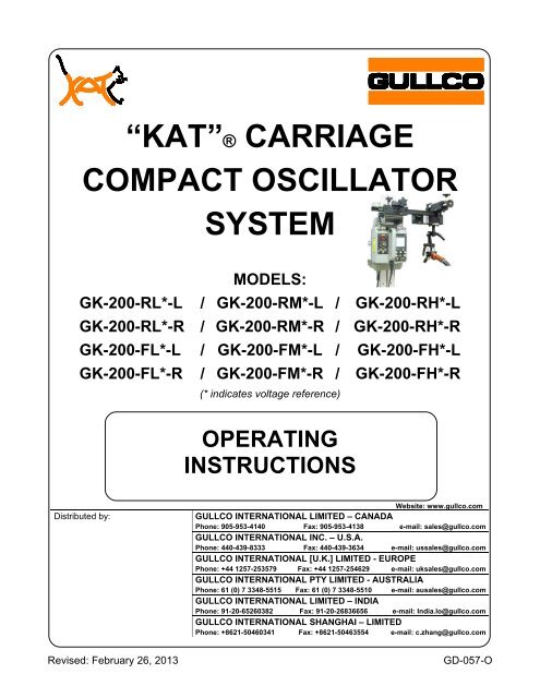
“KAT”® CARRIAGE<br />
COMPACT OSCILLATOR<br />
SYSTEM<br />
MODELS:<br />
GK-200-RL*-L / GK-200-RM*-L / GK-200-RH*-L<br />
GK-200-RL*-R / GK-200-RM*-R / GK-200-RH*-R<br />
GK-200-FL*-L / GK-200-FM*-L / GK-200-FH*-L<br />
GK-200-FL*-R / GK-200-FM*-R / GK-200-FH*-R<br />
(* indicates voltage reference)<br />
OPERATING<br />
INSTRUCTIONS<br />
Distributed by:<br />
Website: www.gullco.com<br />
GULLCO INTERNATIONAL LIMITED – CANADA<br />
Phone: 905-953-4140 Fax: 905-953-4138 e-mail: sales@gullco.com<br />
GULLCO INTERNATIONAL INC. – U.S.A.<br />
Phone: 440-439-8333 Fax: 440-439-3634 e-mail: ussales@gullco.com<br />
GULLCO INTERNATIONAL [U.K.] LIMITED - EUROPE<br />
Phone: +44 1257-253579 Fax: +44 1257-254629 e-mail: uksales@gullco.com<br />
GULLCO INTERNATIONAL PTY LIMITED - AUSTRALIA<br />
Phone: 61 (0) 7 3348-5515 Fax: 61 (0) 7 3348-5510 e-mail: ausales@gullco.com<br />
GULLCO INTERNATIONAL LIMITED – INDIA<br />
Phone: 91-20-65260382 Fax: 91-20-26836656 e-mail: India.lo@gullco.com<br />
GULLCO INTERNATIONAL SHANGHAI – LIMITED<br />
Phone: +8621-50460341 Fax: +8621-50463554 e-mail: c.zhang@gullco.com<br />
Revised: February 26, 2013<br />
GD-057-O
SAFETY INSTRUCTIONS<br />
Although the “KAT” ® Carriage/Compact Oscillator is manufactured for safe and dependable<br />
operation, it is impossible to anticipate those combinations of circumstances which could result in<br />
an accident. An operator of the “KAT” ® Carriage/Compact Oscillator is cautioned to always practice<br />
"Safety First" during each phase of operation, set-up and maintenance.<br />
Read and understand the operation manual before operating or performing service of this<br />
equipment. Become familiar with the machines operation, applications and limitations. Keep the<br />
operation manual in a clean and readily available location.<br />
This equipment is normally used to automate / semi-automate welding or cutting processes. These<br />
processes usually have any combination of the following; bright and hot arcs, flying sparks, fumes,<br />
ultraviolet and infrared radiated energy, hot work-pieces, compressed gases, etc.. The onus is on<br />
the operator of this equipment to know, understand and follow all the safety precautions associated<br />
with the process being used.<br />
A careless operator invites trouble, and failure to follow safety practices may cause serious injury or<br />
even death. Important safety precautions are given in the following:<br />
Electrical Shock Prevention<br />
Do not use this equipment in damp or wet locations.<br />
Do not expose this equipment to rain.<br />
Never carry this equipment by the cables or pull the cables to disconnect from<br />
the receptacle.<br />
Keep all cables from heat, oil and sharp edges.<br />
Inspect all cables periodically and replace if damaged.<br />
Inspect the security of all cables periodically and repair if loose.<br />
Disconnect the power cord when not in use.<br />
Disconnect the power cord positively to prevent electrical shock before<br />
repair and service of the equipment.<br />
Bodily Injury Prevention<br />
Do not wear loose clothing, jewelry and loose, long hair which may get caught<br />
into automatic <strong>system</strong>s or moving parts.<br />
Ensure that the track is well secured when installed in any other position than<br />
flat on a surface.<br />
The track must have a method of safety back-up from falling when suspended,<br />
i.e. chained at the ends, welded to work-piece, etc.<br />
Keep lifting handle dry, clean and free from oil and grease.<br />
Keep hands away from the underside of the “KAT” ® <strong>carriage</strong> when there is the<br />
slightest possibility of it moving.<br />
If flex track is used, exercise extreme caution when mounting and handling the<br />
track, as it is made of spring steel, and therefore poses a potential hazard of<br />
injury due to “whipping”.<br />
If flex track is used, always wear protective gloves when handling the track, to<br />
prevent injury from sharp edges.<br />
1
SAFETY PRECAUTIONS<br />
The following cautionary/warning label is attached to each “KAT” ® <strong>carriage</strong>:-<br />
The above label pictorially represents the following:<br />
“Warning:-<br />
Read the manual before turning the unit on and before performing service.<br />
Also, positively disconnect the unit from all power supplies before servicing!”<br />
IMPORTANT<br />
READ THIS BEFORE OPERATING THE “KAT”® CARRIAGE/COMPACT OSCILLATOR<br />
WARNING! Always turn the main power off before connecting/disconnecting the <strong>oscillator</strong> head<br />
cable to/from the “KAT” ® <strong>carriage</strong>. Failure to comply may result in control damage.<br />
Ensure that an adequate and well-maintained weld return path is provided with good electrical<br />
contact. Failure to do so may result in the welding current passing through the <strong>carriage</strong> and<br />
damaging the wiring and electrical components.<br />
Important information regarding safety and operation of the “GSP” motor control used in the “KAT” ®<br />
<strong>carriage</strong> is contained in a supplemental manual attached at the end of the Technical Manual. It is<br />
equally important to read, understand and apply the information contained within the manual. The<br />
supplemental manual (GD-031) has a title “Technical Information For The <strong>Gullco</strong> “GSP” Micro-<br />
Processor Based, 24 Volt DC Motor Control”, and it’s pages are numbered with a prefix of “T-“.<br />
ALL THE SAFE PRACTICES AND PRECAUTIONS MAY NOT BE GIVEN IN WRITING. SOME<br />
ARE BASED ON COMMON SENSE, BUT OTHERS MAY REQUIRE TECHNICAL<br />
BACKGROUND TO EXPLAIN.<br />
2
“KAT”® CARRIAGE/COMPACT OSCILLATOR COMBINATION<br />
This manual covers the operation instructions of the following “KAT” ® Carriage/Compact Oscillator<br />
<strong>system</strong>s, using Rigid or Flex “KAT” ® , all position, variable speed travel <strong>carriage</strong>s and either Linear<br />
or Radial Oscillator heads (* indicates input voltage: ‘A’ = 42 VAC; ‘B’ = 115 VAC; ‘C’ = 230 VAC):<br />
GK-200-RL*-L / GK-200-RM*-L / GK-200-RH*-L<br />
GK-200-RL*-R / GK-200-RM*-R / GK-200-RH*-R<br />
GK-200-FL*-L / GK-200-FM*-L / GK-200-FH*-L<br />
GK-200-FL*-R / GK-200-FM*-R / GK-200-FH*-R<br />
GENERAL DESCRIPTION<br />
This advanced <strong>Gullco</strong> oscillation package combines the <strong>Gullco</strong> “KAT” ® all position, travel <strong>carriage</strong><br />
with either the Linear or Radial <strong>compact</strong> <strong>oscillator</strong> head and <strong>oscillator</strong> control which is incorporated<br />
into the <strong>carriage</strong>.<br />
The <strong>Gullco</strong> “KAT” ® is a heavy duty, all position travel <strong>carriage</strong>. It is an electrically powered, self<br />
propelled <strong>carriage</strong> that travels in a forward or reverse direction, at precisely controlled speeds,<br />
along a special track. The self aligning wheel <strong>system</strong> of the <strong>carriage</strong> grips the top and bottom of the<br />
track, enabling it to travel along any plane. The bogey wheel assembly keeps the <strong>carriage</strong> snug to<br />
the track, while allowing it to be easily mounted and removed from the track at any point. The<br />
positive drive of the “KAT” ® is obtained from either a pinion that engages with the rack of the rigid<br />
track, or a spherical sprocket gear that engages with slots in the flex track. Both of these <strong>system</strong>s<br />
are driven by a low voltage permanent magnet motor and gear-head power unit assembly. Safety<br />
is greatly enhanced by the use of <strong>Gullco</strong>’s low voltage (24 V), highly advanced control/power supply<br />
<strong>system</strong> that is available in three line voltage inputs... 42, 115 and 230 VAC, single phase, 50/60 Hz,<br />
3
or any unregulated 24 VDC power supply at 220 watts of power. The micro-processor <strong>carriage</strong><br />
motor control offers operator interface of forward, stop, reverse and infinitely variable control of the<br />
speed, within the range of the model, as well as an L.E.D. display indicating speed in either in/min.<br />
or cm/min.<br />
The <strong>Gullco</strong> Linear and Radial <strong>oscillator</strong> heads are <strong>compact</strong>, light weight, yet durable, reciprocating<br />
devices with high torque, high resolution and low vibration stepper motors. They impart a linear,<br />
pendulum or tangential motion to the welding gun. The low voltage Oscillator Control provides a<br />
large, easy to read, multi-page graphical display and offers programmable and electronic<br />
adjustment over the following functions:<br />
Oscillation width<br />
<br />
<br />
<br />
<br />
<br />
<br />
<br />
<br />
Oscillation speed<br />
Independent Left, centre and right dwells<br />
Oscillation centre positioning (steering)<br />
Automatic wire feed activation<br />
Automatic and Manual <strong>carriage</strong> travel activation<br />
Weld travel start delay and weld crater fill delay<br />
Standard (angular) or step (square) pattern oscillation<br />
Multiple oscillation program storage<br />
These features enable precise control over the automated cycle generating accurate and repetitive<br />
weld oscillation.<br />
Adjustable bracketry as well as vertical and horizontal Micro Fine Adjustable Rack Boxes, allow the<br />
welding gun and the <strong>oscillator</strong> head to be easily mounted, adjusted and accurately positioned, in<br />
virtually any plane, off the front or back of the “KAT” ® <strong>carriage</strong>.<br />
INTENDED / FORESEEN USAGE<br />
The <strong>Gullco</strong> “KAT” ® Carriage/Compact Oscillator combination is used throughout the world to<br />
automate and improve the quality and efficiency of the weld produced in automatic mechanized<br />
welding operations. This is achieved through minimizing weld defects such as poor penetration,<br />
incomplete fusion, overlap and undercut. Also, detrimental factors such as poor or awkward<br />
accessibility, operator fatigue, or inconsistent workmanship are eliminated. Required quality levels<br />
are consistently attained and productivity and profitability increased.<br />
Welding guns are readily mounted on the <strong>oscillator</strong> head and either a linear, pendulum or tangential<br />
motion is used to produce either a standard angular or step (square) weld pattern. The track that<br />
the “KAT” ® <strong>carriage</strong> is going to travel along, is positioned so that the “KAT” ® will move the <strong>oscillator</strong><br />
head and welding gun along the desired path and then securely held in place using magnetic or<br />
vacuum activated mounting devices. Safety back-up devices such as chains at the ends of the<br />
track; or welding some track mounting devices to the work-piece; must be implemented whenever<br />
there is a possibility that the equipment may fall due to gravity. By combining welding gun<br />
oscillation movement with the precision controlled travel speed of the “KAT” ® <strong>carriage</strong>, a wide range<br />
of weld patterns can be produced....as described on the following pages.<br />
4
OPERATION<br />
The electrical and mechanical installation of the “KAT” ® Carriage/Compact Oscillator <strong>system</strong> is<br />
explained in the Technical Manual (GD-057-T).<br />
Local Control Devices<br />
Power <strong>On</strong>/Off Switch<br />
Arc Activation Signal Connector<br />
(Trigger Signal)<br />
Fuse Holder<br />
Carriage Motor Control<br />
Oscillator Control<br />
Oscillator Head Connector<br />
The Power <strong>On</strong>/Off switch is used to disconnect the power to the rest of the control circuitry.<br />
I = <strong>On</strong>, O = Off.<br />
WARNING! Always turn the main power off before connecting/disconnecting the <strong>oscillator</strong> head<br />
cable to/from the “KAT” ® <strong>carriage</strong>. Failure to comply may result in control damage.<br />
5
WARNING! The motor and <strong>oscillator</strong> controls must not be continually started and stopped by the<br />
removal and reapplying of power to the controls. Turning the power off to the controls<br />
will not provide instant braking and continued use will damage the controls. <strong>All</strong>ow ten<br />
(10) seconds after the removal of power before reapplying the power to the<br />
equipment.<br />
The Fuse Holder allows accessibility to the main fuse by pushing the cap in towards the main body<br />
and twisting in a counter-clockwise direction.<br />
The Arc Activation Signal Connector is used to interface with the trigger signal of the customers<br />
welding equipment and is used to start/stop the welding process.<br />
Either the Linear or Radial model of <strong>compact</strong> <strong>oscillator</strong> head can be plugged into the Oscillator<br />
Head Connector (control needs to be calibrated to suite the type of head).<br />
"KAT"® CONTROL<br />
Speed & Parameter Value<br />
Display<br />
Forward Motion Commanded<br />
Reverse Motion Commanded<br />
Speed Display Calibrated in<br />
Inches per Minute<br />
Speed Display Calibrated in<br />
Centimeters per Minute<br />
Hold (Stop) Mode Active<br />
Speed Adjustment<br />
Counter-Clockwise = Slower<br />
Clockwise = Faster<br />
Control in Run Mode<br />
Control in Hold (Stop) Mode<br />
Command Forward Motion<br />
Neutral<br />
Command Reverse Motion<br />
The L.E.D. Display<br />
The control has an L.E.D. display that indicates the travel speed in either inches per minute or<br />
centimetres per minute. The display also shows the travel direction accessed as well as the status<br />
of the Stop command.<br />
The Forward and Reverse L.E.D.’s indicate the “KAT” ® <strong>carriage</strong> motor direction<br />
commanded.<br />
6
The “Hold” (stop) L.E.D. will illuminate whenever there is a “Hold” (stop) command<br />
present. This could be any combination of either the “KAT” ® Control Run/Stop switch<br />
or the Oscillator Control Auto/Stop/Run switch being in the Stop position.<br />
Externally, the <strong>Gullco</strong> “KAT” ® Control has switching for Forward/Neutral/Reverse & Run/Stop, as<br />
well as a rotary encoder for speed control.<br />
= “STOP” - This over-rides all other controls and when activated will apply<br />
regenerative breaking to the <strong>carriage</strong> motor to bring it to a dead stop, and will<br />
disallow any further operation of the <strong>carriage</strong> while ever it is in this state. This<br />
position will also reset an error code once the fault has been rectified. The Oscillator<br />
Control will also access this command when it is in the “STOP” mode.<br />
= “RUN” - This removes the “STOP” command and allows the control to assume an<br />
operational status, allowing <strong>carriage</strong> motion when permitted by the <strong>oscillator</strong> control.<br />
This command will be ignored if the Oscillator Control is in the “STOP” mode.<br />
= “FORWARD” - When the switch is in this position, Forward motion is selected as<br />
the desired “KAT” ® <strong>carriage</strong> travel direction.<br />
= “NEUTRAL” - When the switch is in this position, the control will not drive the<br />
“KAT” ® <strong>carriage</strong> motor in either direction.<br />
= “REVERSE” - When the switch is in this position, Reverse motion is selected as<br />
the desired “KAT” ® <strong>carriage</strong> travel direction.<br />
= “SPEED ADJUSTMENT” - By turning the multi turn rotary encoder knob in a<br />
clockwise direction, the <strong>carriage</strong> motor speed will be increased. When rotated in the<br />
counter-clockwise direction, the <strong>carriage</strong> motor speed will decrease. The speed of<br />
the <strong>carriage</strong> travel can be preset, prior to any motion, by placing the<br />
Forward/Neutral/Reverse switch of the “KAT” ® control to “Neutral”. Then by turning<br />
the variable Speed Adjustment knob, the travel speed can be set to the required<br />
value, as indicated in the L.E.D. display.<br />
7
OSCILLATOR CONTROL<br />
A highly sophisticated, yet easy to use, multi-processor based<br />
control drives a high torque, high resolution, low vibration<br />
stepper motor located in the Oscillator Head, allowing the<br />
welding gun to be moved in a precise reciprocative manner.<br />
The control interfaces with the “KAT” ® <strong>carriage</strong> travel and the<br />
trigger signal of the welding equipment. By controlling the<br />
oscillation width, speed, positioning and dwell patterns as well<br />
as the timed activation/deactivation of the “KAT” ® <strong>carriage</strong><br />
travel and the welding process, the quality and appearance of<br />
the weld can be tuned to perfection.<br />
A<br />
B<br />
C<br />
The A, B & C rotary switches will increase<br />
(clockwise adjustment) or decrease (counterclockwise<br />
adjustment) the A, B & C location<br />
dwells respectively by 0.1 second increments,<br />
from a minimum of zero up to a maximum of<br />
9.9 seconds. The current values are displayed<br />
on the LCD screen. These adjustments can be<br />
changed at any time before, or during,<br />
operation and will take effect on the next<br />
relevant dwell location. The orientation of the<br />
ABC locations of the Oscillator Head can be<br />
altered (programmed) to match the orientation<br />
of the control (see the Technical Manual, GD-<br />
057-T for details).<br />
The Dwell Enable/Disable switch will allow the<br />
<strong>oscillator</strong> to perform the A, B & C location dwell<br />
timing cycles while running when Enabled<br />
( ) or will not perform the dwells when<br />
Disabled ( ). This Enable/Disable selection<br />
can be made at any time and will take effect<br />
immediately. When disabled the LCD screen<br />
will show all dwell times as zero and the dwell<br />
disabled icons crossed-out, as shown<br />
adjacent:<br />
The W rotary switch increases (clockwise<br />
adjustment) or decreases (counter-clockwise<br />
adjustment) the total width of the oscillation<br />
stroke (A to C). The increments of adjustment<br />
and the minimum and maximum allowable stroke<br />
widths are dependent on the type of Oscillator<br />
A<br />
0.0<br />
W<br />
CM<br />
1.06<br />
B<br />
0.0<br />
4<br />
C<br />
0.0<br />
S<br />
CM/MIN<br />
Head used and the preferred units of measurement (see the Technical Manual, GD-<br />
057-T for details). The current value is displayed on the LCD screen. Width<br />
adjustments can be changed at any time before or during operation and will take<br />
effect on the next travel past the B location. Note:- there is a width range where the<br />
oscillation stroke is too small to permit A, B & C dwells to work.<br />
72<br />
8
The S rotary switch increases (clockwise adjustment) or decreases (counterclockwise<br />
adjustment) the oscillation stroke speed. The increments of adjustment<br />
and the minimum and maximum allowable stroke speeds are dependent on the type<br />
of Oscillator Head used and the preferred units of measurement (see the Technical<br />
Manual, GD-057-T for details). The current value is displayed on the LCD screen.<br />
Speed adjustments can be changed at any time before or during operation and will<br />
take effect immediately.<br />
The Center Position Adjustment rotary switch will allow the operator to jog the center<br />
position (B location) either to the left or to the right. This rotary switch can be used to<br />
position the welding gun prior to oscillation when the Manual/Hold/Auto switch is in<br />
the Manual position. To make adjustments (steering) while welding, rotate the<br />
Center Position Adjustment rotary switch in the appropriate direction until the centre<br />
of the oscillation has moved to the desired location. The size of these centre<br />
adjustment (steering) increments can be programmed to be as large or small as<br />
preferred (see the Technical Manual, GD-057-T for details).<br />
The Arc Enable/Disable switch will allow the operator to either Enable ( ) or<br />
Disable ( ) the arc activation signal to the welding equipment. This Enable/Disable<br />
selection can be made at any time and will take effect immediately.<br />
When Enabled ( ), the arc activation signal will be energized while-ever the<br />
<strong>oscillator</strong> is running. When the arc activation signal is energized, the arc<br />
activation signal icon in the lower left corner of the LCD screen will appear as<br />
follows:<br />
When Disabled ( ), the arc activation signal will de-energize (if applicable) and<br />
remain de-energized. While ever the arc activation signal is de-energized, the<br />
arc activation signal icon in the lower left corner of the LCD screen will appear as<br />
follows:<br />
The Manual/Hold/Auto switch is used to start and stop the <strong>oscillator</strong> equipment as<br />
well as interfacing with the “KAT” ® travel <strong>carriage</strong>.<br />
In the Manual position ( ), the arc activation signal and the <strong>oscillator</strong> head<br />
are inactive, and the “KAT” ® <strong>carriage</strong> will operate manually. The <strong>carriage</strong> release<br />
icon on the lower right corner of the LCD screen will appear as follows:<br />
The Hold position ( ), over-rides all other controls and when activated will<br />
apply the Hold (stop) signal to the “KAT” ® <strong>carriage</strong> control, and will disallow any<br />
further operation of the “KAT” ® while ever it is in this state. The arc activation<br />
signal and the Oscillator Head remain inactive in this mode. The <strong>carriage</strong> hold<br />
icon on the lower right corner of the LCD screen will appear as follows:<br />
When placed in the Auto cycle position ( ), the arc activation signal will<br />
energize (only if the Arc Enable/Disable switch is in the Enable state) and the<br />
Oscillator Head will start its oscillation motion. After the programmable Travel<br />
Start time delay the <strong>oscillator</strong> control will deactivate its Hold (stop) command to<br />
the “KAT” ® <strong>carriage</strong> control, thus allowing it to travel. While ever the Hold (stop)<br />
9
command is released to the “KAT” ® <strong>carriage</strong>, the <strong>carriage</strong> release icon on the<br />
lower right corner of the LCD screen will appear as follows:<br />
The Program push button changes the control state from running (operational) mode<br />
to programming mode, and back to running mode. While-ever the control is in<br />
programming mode, the program icon on the lower right corner of the LCD screen<br />
will appear as follows:<br />
AUTOMATIC CYCLE OPERATION<br />
To perform an automatic welding cycle:<br />
1. Place the Oscillator control Manual/Hold/Auto switch in the Hold position.<br />
2. Place the “KAT” ® <strong>carriage</strong> control Run/Stop switch in the Run position.<br />
3. Set the “KAT” ® <strong>carriage</strong> travel speed by placing the “KAT” ® <strong>carriage</strong> control<br />
Forward/Neutral/Reverse switch in the Neutral position then rotate the Speed Adjustment<br />
knob until the desired speed is displayed.<br />
4. Place the “KAT” ® <strong>carriage</strong> control Forward/Neutral/Reverse switch to the desired weld travel<br />
direction.<br />
5. Using the devices on the Oscillator control, set the desired oscillation width, oscillation<br />
speed and dwells.<br />
6. When the Oscillator control Manual/Hold/Auto switch is placed in the Auto position, the<br />
programmable audible warning buzzer duration elapses while the optional buzzer is<br />
energized (if the optional buzzer is not installed this timing cycle is usually programmed off).<br />
Then the oscillation motion will commence and the arc activation signal will be energized (if<br />
the Arc Enable/Disable switch is in the Enable position). Following the Travel Motion Delay,<br />
the Hold (stop) signal to the “KAT” ® <strong>carriage</strong> control is released and the <strong>carriage</strong> starts its<br />
weld travel.<br />
7. When the Oscillator control Manual/Hold/Auto switch is placed in the Hold position, the Hold<br />
(stop) signal to the “KAT” ® <strong>carriage</strong> control is energized again, stopping the “KAT” ® <strong>carriage</strong><br />
travel, and the Oscillator Head motion is stopped. After a programmable Crater Fill Delay<br />
the arc activation signal is de-energized and the automatic cycle is completed.<br />
The following are some notes on the operation of the control.<br />
1. When the oscillation is to start, the Oscillator control will always assume that the <strong>oscillator</strong><br />
head/slide is resting at the “Oscillation Rest Location” (4 th Field of the Features & Setup<br />
screen, described later in this manual) and will travel in the appropriate direction<br />
accordingly. I.e. if the “Oscillation Rest Location” field is set to C, the <strong>oscillator</strong> will start its<br />
oscillation cycle by moving in the relevant direction toward the B (center) location by a<br />
distance of half the width value (W).<br />
10
There are two levels of programming mode:<br />
PROGRAMMING<br />
‣ General Programming Mode: this first level of programmable features is meant to be<br />
easily accessible to the operator and requires that the Program push button ( ) be<br />
pressed for a minimum of two (2) seconds, but no more than ten (10) seconds, while the<br />
Manual/Hold/Auto switch is either in the Manual or Hold position. The screens that are<br />
accessible under this mode are:<br />
o Feature/Set-up screen and;<br />
o 10 x Auto cycle storage screens.<br />
‣ Advanced Programming Mode: this second level of programmable features is meant<br />
only to be used by higher level and/or qualified users and requires that the Program<br />
push button ( ) be pressed for more than ten (10) seconds while the<br />
Manual/Hold/Auto switch is either in the Manual or Hold position. The screen that is<br />
accessible under this mode is:<br />
o Motor Setup screen (see the Technical Manual, GD-057-T for details)<br />
To change state from programming mode (any screen) to running (operational) mode, press the<br />
Program push button ( ) once (it does not need to be pressed for any specific duration). The<br />
various values and settings will be saved.<br />
When in the programming mode, only the A, B & C rotary switches and the Program push button<br />
will be used. <strong>All</strong> other toggle and rotary switches will be ignored.<br />
‣ The A rotary switch is used to navigate forward and backward between screens (pages).<br />
‣ The B rotary switch is used to navigate forward and backward between adjustable fields of<br />
the current screen (page). The contents of the selected field will flash to indicate which field<br />
is currently selected.<br />
‣ The C rotary switch is used to change the value/setting of the currently selected adjustable<br />
field.<br />
‣ The Program push button ( ) is used to save all values and settings, exit programming<br />
mode and return to the running (operational) mode.<br />
Note: If the Manual/Hold/Auto switch is placed in the Auto position when the control is in the<br />
programming mode, the arc signal relay will not energize, the <strong>oscillator</strong> will not start to run and the<br />
<strong>carriage</strong> Hold (stop) signal will not be de-energized. If the switch remains in the Auto position when<br />
the control returns to the running (operational) mode, the <strong>system</strong> will remain display “ER.1”,<br />
requiring the switch to be placed in the Hold position to reset.<br />
While-ever the control is in programming mode, the program icon is displayed in the lower right<br />
hand corner of the LCD screen as follows:<br />
11
The sequence of level 1 (General Programming Mode) program screen displays is as follows:<br />
Rotate the A rotary switch<br />
clockwise to move forward<br />
through the screens.<br />
Rotate the A rotary switch<br />
counter-clockwise to move<br />
backwards through the<br />
screens.<br />
12
The Features & Setup Screen<br />
1 st Field<br />
2 nd Field<br />
3 rd Field<br />
4 th Field<br />
5 th Field<br />
6 th Field<br />
The Features & Setup Screen has the following features:<br />
1 st Field = The Auto Cycle storage number to be recalled. The number shown in this field will be<br />
the program that will be copied from storage and applied to the running (operational)<br />
mode values when exited from programming mode. The choices are 0, 1, 2, 3, 4, 5, 6,<br />
7, 8, 9, or 10 (surrounded by the auto cycle symbol). When the value is 0, the existing<br />
oscillation values last used will not be over-written. Each time the Features and Setup<br />
screen is opened, the value in this field defaults to 0.<br />
2 nd Field = The Oscillation mode. There are three pictorial modes to choose from:<br />
‣ Normal Oscillation. This is where the travel <strong>carriage</strong> is allowed to<br />
run continuously through the oscillation cycles. This is the<br />
factory default setting.<br />
‣ Step during Dwells. This is where the travel <strong>carriage</strong><br />
is only allowed to run during each of the A, B or C<br />
location dwells. This mode will only work effectively if<br />
the dwell times are not too small.<br />
‣ Step during Oscillation stroke. This is where the travel <strong>carriage</strong> is<br />
only allowed to run during each oscillation stroke (i.e. <strong>carriage</strong> is<br />
not permitted to run during each of the A, B or C location dwells).<br />
This mode will only work effectively if the dwell times and the<br />
oscillation width are not too small.<br />
13
3 rd Field = Travel Motion Delay. This sets a timing delay at the start of an automatic cycle, from<br />
the time that the arc activation signal is energized until the time that the travel <strong>carriage</strong><br />
Hold (stop) signal is de-energized. I.e. a timing cycle to allow the arc to strike and<br />
establish, before <strong>carriage</strong> motion. The choices available are from 0.0 to 9.9 seconds<br />
in 0.1 second increments. The factory default setting is 0.3 seconds.<br />
4 th Field = Crater Fill Delay. This sets a timing delay at the end of an automatic cycle, from the<br />
time that the travel <strong>carriage</strong> Hold (stop) signal is re-energized and the oscillation<br />
motion stops until the arc activation signal is de-energized. I.e. a timing cycle to allow<br />
the welding to continue after the welding motion ceases. The choices available are<br />
from 0.0 to 9.9 seconds in 0.1 second increments. The factory default setting is 0.5<br />
seconds.<br />
5 th Field = Oscillation Rest Location. This setting dictates where the <strong>oscillator</strong> stops at the end of<br />
an oscillation cycle (and therefore assumed location at the start of an oscillation cycle).<br />
The choices are A, B or C. The factory default setting is B.<br />
6 th Field = Audible Warning Buzzer Duration. This sets the timing cycle for the optional audible<br />
warning prior to the start of each Auto cycle. The choices are from 0 to 9 seconds in 1<br />
second increments.<br />
‣ When the value is greater than 0, the following icon is displayed:<br />
‣ When the value is 0, the following icon is displayed:<br />
Notes: <strong>All</strong> fields except the 1 st Field retain the last value entered.<br />
14
Auto Cycle Storage Screens<br />
There are a total of ten (10) Auto Cycle Storage Screens, and each screen is identified by the “Auto<br />
Cycle Storage Number” (numbered 1 to 10) as shown in the following image. The units of measure<br />
for the oscillation width (W) and the oscillation speed (S) are programmable (level 2 - Advanced<br />
Programming Mode). If the units of measure change, all width and speed fields will need to be<br />
manually converted. To make changes to these screens/fields use the A, B & C rotary switches as<br />
described on page 11. <strong>All</strong> the Auto Cycle Storage Screens have the following features:<br />
1 st Field<br />
2 nd Field<br />
3 rd Field<br />
Units<br />
4 th Field<br />
5 th Field<br />
Auto Cycle Storage Number<br />
1 st Field = The A Location Dwell Time. This sets the time duration that the oscillation stroke will<br />
dwell (pause) each time the A location is reached. The choices available are from 0.0<br />
to 9.9 seconds in 0.1 second increments.<br />
2 nd Field = The B Location Dwell Time. This sets the time duration that the oscillation stroke will<br />
dwell (pause) each time the B (center) location is reached. The choices available are<br />
from 0.0 to 9.9 seconds in 0.1 second increments.<br />
3 rd Field = The C Location Dwell Time. This sets the time duration that the oscillation stroke will<br />
dwell (pause) each time the C location is reached. The choices available are from 0.0<br />
to 9.9 seconds in 0.1 second increments.<br />
4 th Field = The Oscillation Width. The value of this field sets the total width of the oscillation<br />
stroke (A to C). The increments of adjustment and the minimum and maximum<br />
allowable stroke widths are dependent on the type of Oscillator Head used and the<br />
preferred units of measurement (see the Technical Manual, GD-057-T for details).<br />
Note:- there is a width range where the oscillation stroke is too small to permit A, B &<br />
C dwells to work.<br />
5 th Field = The Oscillation Speed. The value of this field sets the oscillation stroke speed. The<br />
increments of adjustment and the minimum and maximum allowable stroke speeds are<br />
dependent on the type of Oscillator Head used and the preferred units of<br />
measurement (see the Technical Manual, GD-057-T for details).<br />
15
ERROR CODES<br />
Error codes are displayed on the LCD screen as shown adjacent.<br />
ER.1<br />
ER.2<br />
If the Oscillator Controls’ Manual/Hold/Auto switch is in the<br />
Auto position on power-up, the control will display ER.1 and<br />
not permit an automatic cycle to start. This prevents the<br />
undesirable start of an automatic cycle on power-up. To<br />
reset the error, place the switch in the Hold position.<br />
When the Oscillator Control is programmed to operate a Linear Oscillator Head (preferred units<br />
of measurement are either Inches or CM), the control monitors limit switches located within the<br />
Oscillator Head to prevent over-travel. If either, or both, of these limit switches are open circuit,<br />
the control will display ER.2 and not permit normal operation. This situation could include the<br />
following possibilities:<br />
<br />
Manually jogging the slide too far. To reset, manually jog the slide in the opposite<br />
direction.<br />
The over-travel occurred during Oscillation. This could be due; to the oscillation<br />
width being set too large for the stroke of the slide; the starting location of the<br />
<strong>oscillator</strong> slide relative to the oscillation width and direction; or through making center<br />
position adjustments (steering), resulting in slide over-travel. To reset, make the<br />
necessary manual and/or programming adjustments and restart the automatic cycle.<br />
It is recommended that the <strong>oscillator</strong> be set so that the oscillation occurs in the<br />
centre of the slides stroke to permit center position adjustments (steering) without<br />
activating the over-travel limit switches.<br />
<br />
Powering up the “KAT” ® Carriage/Compact Oscillator without having a Linear Head<br />
connected. To reset, either power down and attach a Linear Oscillator Head or<br />
connect a Radial Oscillator Head and reprogram the Oscillator Control accordingly.<br />
o WARNING! Always turn the main power off before<br />
connecting/disconnecting the <strong>oscillator</strong> head cable to/from the “KAT” ® <strong>carriage</strong>.<br />
Failure to comply may result in control damage.<br />
OPTIONAL ACCESSORIES<br />
GK- 201-121 Optional Audible Buzzer Kit – Includes audible buzzer and wiring harness to<br />
interface with the Oscillator Control, providing a programmable duration for the<br />
audible warning buzzer to activate before starting an automatic cycle.<br />
16
REVISIONS LIST<br />
July, 2008<br />
Overall<br />
General revision.<br />
Aug, 2010<br />
Title Page Updated <strong>Gullco</strong> contact details.<br />
Page 9 Updated description of The Center Position Adjustment rotary switch, was a 3<br />
position center maintained toggle switch.<br />
Back Page Updated back page.<br />
Feb, 2013<br />
Title Page<br />
Updated <strong>Gullco</strong> [U.K.] e-mail contact details.<br />
ADDITIONAL NOTES<br />
Specifications and products are subject to change without notice.<br />
KAT, Moggy, Sam, KATBAK & KBM are registered trademarks of <strong>Gullco</strong> International Enterprises Ltd.<br />
<strong>On</strong>ly use genuine/authorized replacement parts.<br />
17
www.GULLCO.com


