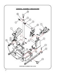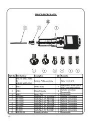
âkatâ® carriage compact oscillator system - All Categories On Gullco ...
âkatâ® carriage compact oscillator system - All Categories On Gullco ...
âkatâ® carriage compact oscillator system - All Categories On Gullco ...
- No tags were found...

You also want an ePaper? Increase the reach of your titles
YUMPU automatically turns print PDFs into web optimized ePapers that Google loves.
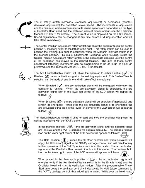
The S rotary switch increases (clockwise adjustment) or decreases (counterclockwise<br />
adjustment) the oscillation stroke speed. The increments of adjustment<br />
and the minimum and maximum allowable stroke speeds are dependent on the type<br />
of Oscillator Head used and the preferred units of measurement (see the Technical<br />
Manual, GD-057-T for details). The current value is displayed on the LCD screen.<br />
Speed adjustments can be changed at any time before or during operation and will<br />
take effect immediately.<br />
The Center Position Adjustment rotary switch will allow the operator to jog the center<br />
position (B location) either to the left or to the right. This rotary switch can be used to<br />
position the welding gun prior to oscillation when the Manual/Hold/Auto switch is in<br />
the Manual position. To make adjustments (steering) while welding, rotate the<br />
Center Position Adjustment rotary switch in the appropriate direction until the centre<br />
of the oscillation has moved to the desired location. The size of these centre<br />
adjustment (steering) increments can be programmed to be as large or small as<br />
preferred (see the Technical Manual, GD-057-T for details).<br />
The Arc Enable/Disable switch will allow the operator to either Enable ( ) or<br />
Disable ( ) the arc activation signal to the welding equipment. This Enable/Disable<br />
selection can be made at any time and will take effect immediately.<br />
When Enabled ( ), the arc activation signal will be energized while-ever the<br />
<strong>oscillator</strong> is running. When the arc activation signal is energized, the arc<br />
activation signal icon in the lower left corner of the LCD screen will appear as<br />
follows:<br />
When Disabled ( ), the arc activation signal will de-energize (if applicable) and<br />
remain de-energized. While ever the arc activation signal is de-energized, the<br />
arc activation signal icon in the lower left corner of the LCD screen will appear as<br />
follows:<br />
The Manual/Hold/Auto switch is used to start and stop the <strong>oscillator</strong> equipment as<br />
well as interfacing with the “KAT” ® travel <strong>carriage</strong>.<br />
In the Manual position ( ), the arc activation signal and the <strong>oscillator</strong> head<br />
are inactive, and the “KAT” ® <strong>carriage</strong> will operate manually. The <strong>carriage</strong> release<br />
icon on the lower right corner of the LCD screen will appear as follows:<br />
The Hold position ( ), over-rides all other controls and when activated will<br />
apply the Hold (stop) signal to the “KAT” ® <strong>carriage</strong> control, and will disallow any<br />
further operation of the “KAT” ® while ever it is in this state. The arc activation<br />
signal and the Oscillator Head remain inactive in this mode. The <strong>carriage</strong> hold<br />
icon on the lower right corner of the LCD screen will appear as follows:<br />
When placed in the Auto cycle position ( ), the arc activation signal will<br />
energize (only if the Arc Enable/Disable switch is in the Enable state) and the<br />
Oscillator Head will start its oscillation motion. After the programmable Travel<br />
Start time delay the <strong>oscillator</strong> control will deactivate its Hold (stop) command to<br />
the “KAT” ® <strong>carriage</strong> control, thus allowing it to travel. While ever the Hold (stop)<br />
9