âkatâ® carriage compact oscillator system - All Categories On Gullco ...
âkatâ® carriage compact oscillator system - All Categories On Gullco ...
âkatâ® carriage compact oscillator system - All Categories On Gullco ...
- No tags were found...

You also want an ePaper? Increase the reach of your titles
YUMPU automatically turns print PDFs into web optimized ePapers that Google loves.
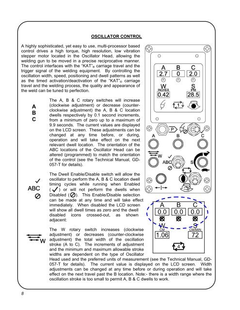
OSCILLATOR CONTROL<br />
A highly sophisticated, yet easy to use, multi-processor based<br />
control drives a high torque, high resolution, low vibration<br />
stepper motor located in the Oscillator Head, allowing the<br />
welding gun to be moved in a precise reciprocative manner.<br />
The control interfaces with the “KAT” ® <strong>carriage</strong> travel and the<br />
trigger signal of the welding equipment. By controlling the<br />
oscillation width, speed, positioning and dwell patterns as well<br />
as the timed activation/deactivation of the “KAT” ® <strong>carriage</strong><br />
travel and the welding process, the quality and appearance of<br />
the weld can be tuned to perfection.<br />
A<br />
B<br />
C<br />
The A, B & C rotary switches will increase<br />
(clockwise adjustment) or decrease (counterclockwise<br />
adjustment) the A, B & C location<br />
dwells respectively by 0.1 second increments,<br />
from a minimum of zero up to a maximum of<br />
9.9 seconds. The current values are displayed<br />
on the LCD screen. These adjustments can be<br />
changed at any time before, or during,<br />
operation and will take effect on the next<br />
relevant dwell location. The orientation of the<br />
ABC locations of the Oscillator Head can be<br />
altered (programmed) to match the orientation<br />
of the control (see the Technical Manual, GD-<br />
057-T for details).<br />
The Dwell Enable/Disable switch will allow the<br />
<strong>oscillator</strong> to perform the A, B & C location dwell<br />
timing cycles while running when Enabled<br />
( ) or will not perform the dwells when<br />
Disabled ( ). This Enable/Disable selection<br />
can be made at any time and will take effect<br />
immediately. When disabled the LCD screen<br />
will show all dwell times as zero and the dwell<br />
disabled icons crossed-out, as shown<br />
adjacent:<br />
The W rotary switch increases (clockwise<br />
adjustment) or decreases (counter-clockwise<br />
adjustment) the total width of the oscillation<br />
stroke (A to C). The increments of adjustment<br />
and the minimum and maximum allowable stroke<br />
widths are dependent on the type of Oscillator<br />
A<br />
0.0<br />
W<br />
CM<br />
1.06<br />
B<br />
0.0<br />
4<br />
C<br />
0.0<br />
S<br />
CM/MIN<br />
Head used and the preferred units of measurement (see the Technical Manual, GD-<br />
057-T for details). The current value is displayed on the LCD screen. Width<br />
adjustments can be changed at any time before or during operation and will take<br />
effect on the next travel past the B location. Note:- there is a width range where the<br />
oscillation stroke is too small to permit A, B & C dwells to work.<br />
72<br />
8