Download 2005 Chrysler Pacifica Touring
Download 2005 Chrysler Pacifica Touring
Download 2005 Chrysler Pacifica Touring
- No tags were found...

You also want an ePaper? Increase the reach of your titles
YUMPU automatically turns print PDFs into web optimized ePapers that Google loves.
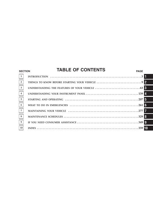
SECTION<br />
TABLE OF CONTENTS<br />
PAGE<br />
1 INTRODUCTION .............................................................3 1<br />
2 THINGS TO KNOW BEFORE STARTING YOUR VEHICLE ..............................9 2<br />
3 UNDERSTANDING THE FEATURES OF YOUR VEHICLE ..............................63 3<br />
4 UNDERSTANDING YOUR INSTRUMENT PANEL ...................................139 4<br />
5 STARTING AND OPERATING .................................................207 5<br />
6 WHAT TO DO IN EMERGENCIES ..............................................261 6<br />
7 MAINTAINING YOUR VEHICLE ...............................................277 7<br />
8 MAINTENANCE SCHEDULES ..................................................329 8<br />
9 IF YOU NEED CONSUMER ASSISTANCE .........................................349 9<br />
10 INDEX ....................................................................359 10
INTRODUCTION<br />
1<br />
CONTENTS<br />
Introduction ........................... 4<br />
How To Use This Manual .................. 4<br />
Warnings And Cautions ................... 6<br />
Vehicle Identification Number ............... 6<br />
Vehicle Modifications / Alterations ........... 7
4 INTRODUCTION<br />
INTRODUCTION<br />
This manual has been prepared with the assistance of<br />
service and engineering specialists to acquaint you with<br />
the operation and maintenance of your new vehicle. It is<br />
supplemented by a Warranty Information Booklet and<br />
various customer oriented documents. You are urged to<br />
read these publications carefully. Following the instructions<br />
and recommendations in this manual will help<br />
assure safe and enjoyable operation of your vehicle.<br />
NOTE: After you read the manual, it should be stored<br />
in the vehicle for convenient reference and remain with<br />
the vehicle when sold, so that the new owner will be<br />
aware of all safety warnings.<br />
When it comes to service, remember that your dealer<br />
knows your vehicle best, has the factory-trained technicians<br />
and genuine Mopar parts, and is interested in<br />
your satisfaction.<br />
WARNING!<br />
Engine exhaust, some of its constituents, and certain<br />
vehicle components contain or emit chemicals<br />
known to the State of California to cause cancer and<br />
birth defects or other reproductive harm. In addition,<br />
certain fluids contained in vehicles and certain products<br />
of component wear contain or emit chemicals<br />
known to the State of California to cause cancer and<br />
birth defects or other reproductive harm.<br />
HOW TO USE THIS MANUAL<br />
Consult the table of contents to determine which section<br />
contains the information you desire.<br />
The detailed index, at the rear of this manual, contains a<br />
complete listing of all subjects.<br />
Consult the following table for a description of the<br />
symbols that may be used on your vehicle or throughout<br />
this owner’s manual:
INTRODUCTION 5<br />
1
6 INTRODUCTION<br />
WARNINGS AND CAUTIONS<br />
This manual contains WARNINGS against operating<br />
procedures which could result in an accident or bodily<br />
injury. It also contains CAUTIONS against procedures<br />
which could result in damage to your vehicle. If you do<br />
not read this entire manual you may miss important<br />
information. Observe all Warnings and Cautions.<br />
VEHICLE IDENTIFICATION NUMBER<br />
The vehicle identification number (VIN) is found on the<br />
left front corner of the instrument panel, visible from<br />
outside of the vehicle through the windshield. This<br />
number also appears on the Automobile Information<br />
Disclosure Label affixed to a window on your vehicle.<br />
Save this label for a convenient record of your vehicle<br />
identification number and optional equipment.<br />
NOTE:<br />
It is illegal to remove the VIN plate.
INTRODUCTION 7<br />
VEHICLE MODIFICATIONS / ALTERATIONS<br />
WARNING!<br />
1<br />
Any modifications or alterations to this vehicle<br />
could seriously affect its roadworthiness and safety<br />
and may lead to an accident resulting in serious<br />
injury or death.
THINGS TO KNOW BEFORE STARTING YOUR VEHICLE<br />
CONTENTS<br />
2<br />
A Word About Your Keys ..................11<br />
▫ Ignition Key Removal ...................11<br />
▫ Key-In-Ignition Reminder ................12<br />
Sentry Key ............................12<br />
▫ Replacement Keys ......................14<br />
▫ Customer Key Programming ..............14<br />
▫ General Information ....................15<br />
Illuminated Entry System ..................15<br />
Door Locks ............................16<br />
▫ Manual Door Locks .....................16<br />
▫ Power Door Locks .....................16<br />
▫ Child Protection Door Lock ...............18<br />
Remote Keyless Entry .....................19<br />
▫ To Unlock The Doors And Liftgate ..........20<br />
▫ To Lock The Doors And Liftgate ............21<br />
▫ Using The Panic Alarm ..................21<br />
▫ To Program Transmitters .................21<br />
▫ To Open/Close Power Liftgate — If Equipped . .22
10 THINGS TO KNOW BEFORE STARTING YOUR VEHICLE<br />
▫ To Turn Off “Flash Lights On Lock/Unlock” . . .22<br />
▫ General Information ....................23<br />
▫ Transmitter Battery Service ...............23<br />
Vehicle Theft Alarm ......................24<br />
Liftgate ...............................26<br />
▫ Power Liftgate — If Equipped .............27<br />
Windows .............................29<br />
▫ Power Windows .......................29<br />
Occupant Restraints ......................30<br />
▫ Lap/Shoulder Belts .....................31<br />
▫ Lap/Shoulder Belt Untwisting Procedure .....37<br />
▫ Seat Belt Pretensioners ...................39<br />
▫ Enhanced Driver Seat Belt Reminder System<br />
(BeltAlert) ...........................39<br />
▫ Seat Belts And Pregnant Women ............41<br />
▫ Seat Belt Extender ......................41<br />
▫ Driver And Front Passenger Supplemental<br />
Restraint System - Airbag ................42<br />
▫ Side Airbags Supplemental Restraint System (SRS)<br />
— If Equipped ........................48<br />
▫ Child Restraint ........................51<br />
Engine Break-In Recommendations ...........59<br />
Safety Tips ............................60<br />
▫ Exhaust Gas ..........................60<br />
▫ Safety Checks You Should Make Inside<br />
The Vehicle ..........................61<br />
▫ Periodic Safety Checks You Should Make Outside<br />
The Vehicle ..........................62
THINGS TO KNOW BEFORE STARTING YOUR VEHICLE 11<br />
A WORD ABOUT YOUR KEYS<br />
You can insert the double sided keys into the locks with<br />
either side up.<br />
be used to order duplicate keys from your dealer. Ask<br />
your dealer for these numbers and keep them in a safe<br />
place.<br />
Ignition Key Removal<br />
The shift lever must be in PARK. Turn the key to the<br />
LOCK position, then remove the key.<br />
2<br />
The dealer that sold you your new vehicle has the key<br />
code numbers for your vehicle locks. These numbers can
12 THINGS TO KNOW BEFORE STARTING YOUR VEHICLE<br />
NOTE: The power window switches, radio, power<br />
sunroof, and power outlets will remain active for up to 45<br />
seconds after the ignition switch has been turned off.<br />
Opening either front door will cancel this feature.<br />
WARNING!<br />
Leaving children in a vehicle unattended is dangerous<br />
for a number of reasons. A child or others could<br />
be injured. Children should be warned not to touch<br />
the parking brake, brake pedal or the gear selector<br />
lever. Don’t leave the keys in the ignition. A child<br />
could operate power windows, other controls, or<br />
move the vehicle.<br />
CAUTION!<br />
An unlocked car is an invitation to thieves. Always<br />
remove key from the ignition and lock all doors<br />
when leaving the vehicle unattended.<br />
Key-In-Ignition Reminder<br />
If you open the driver’s door and the key is in the ignition<br />
switch, a chime will sound to remind you to remove the<br />
key.<br />
SENTRY KEY<br />
The Sentry Key Immobilizer System prevents unauthorized<br />
operation of the vehicle by disabling the engine.<br />
The system will shut the engine off after 2 seconds of<br />
running if an invalid key is used to start the vehicle. This<br />
system utilizes ignition keys which have an electronic
THINGS TO KNOW BEFORE STARTING YOUR VEHICLE 13<br />
chip (transponder) embedded into them. Only keys that<br />
have been programmed to the vehicle can be used to start<br />
and operate the vehicle.<br />
The Sentry Key Immobilizer System does not need to be<br />
armed or activated. Operation of the system is automatic<br />
regardless of whether or not the vehicle is locked or<br />
unlocked. During normal operation, the Theft Alarm/<br />
Immobilizer Light will come on for three (3) seconds<br />
immediately after the ignition switch is turned on for a<br />
bulb check. Afterwards, if the bulb remains on, this<br />
indicates a problem with the electronics.<br />
If the bulb begins to flash after the bulb check, this<br />
indicates that an invalid key has been used to start the<br />
vehicle. Both of these conditions will result in the engine<br />
being shut off after two (2) seconds of running.<br />
Keep in mind that a key which has not been programmed<br />
is also considered an invalid key even if it is cut to fit the<br />
ignition lock cylinder for that vehicle.<br />
If the Theft Alarm/Immobilizer Light comes on during<br />
normal vehicle operation (vehicle has been running for<br />
longer than 10 seconds), a fault has been detected in the<br />
electronics and the vehicle should be serviced as soon as<br />
possible.<br />
NOTE:<br />
• The Sentry Key Immobilizer System is not compatible<br />
with remote starting systems. Use of these systems<br />
may result in vehicle starting problems and loss of<br />
security protection.<br />
• Exxon/Mobil Speed Pass, additional Sentry Keys, or<br />
any other transponder equipped components on the<br />
same keychain will not cause a key-related (transponder)<br />
fault unless the additional part is physically held<br />
against the ignition key being used when starting the<br />
vehicle. Cell phones, pagers, or other RF electronics<br />
will not cause interference with this system.<br />
2
14 THINGS TO KNOW BEFORE STARTING YOUR VEHICLE<br />
All of the keys provided with your new vehicle have<br />
been programmed to the vehicle electronics.<br />
Replacement Keys<br />
NOTE: Only keys that have been programmed to the<br />
vehicle electronics can be used to start the vehicle. Once<br />
a Sentry Key has been programmed to a vehicle, it can<br />
not be programmed to any other vehicle.<br />
At the time of purchase, the original owner is provided<br />
with a four digit PIN number. This number is required<br />
for dealer replacement of keys. Duplication of keys may<br />
be performed at an authorized dealer or by using the<br />
Customer Key Programming procedure. This procedure<br />
consists of programming a blank key to the vehicle<br />
electronics. A blank key is one which has never been<br />
programmed.<br />
NOTE: When having the Sentry Key Immobilizer<br />
System serviced, bring all vehicle keys with you to the<br />
dealer.<br />
Customer Key Programming<br />
You can program new sentry keys to the system if you<br />
have two valid sentry keys by performing the following<br />
procedure:<br />
1. Cut the additional Sentry Key Transponder blank(s) to<br />
match the ignition switch lock cylinder key code.<br />
2. Insert the first valid key into the ignition switch and<br />
turn the ignition switch ON for at least 3 seconds but no<br />
longer than 15 seconds. Turn the ignition switch OFF and<br />
remove the first key.<br />
3. Insert the second valid key and turn the ignition<br />
switch ON within 15 seconds. After ten seconds a chime<br />
will sound and the Theft Alarm Light will begin to flash.<br />
Turn the ignition switch OFF and remove the second key.
THINGS TO KNOW BEFORE STARTING YOUR VEHICLE 15<br />
4. Insert a blank Sentry Key into the ignition switch and<br />
turn the ignition switch ON within 60 seconds. After 10<br />
seconds a single chime will sound. The Theft Alarm Light<br />
will stop flashing, turn on for 3 seconds; then turn off.<br />
The new Sentry Key has been programmed. The Keyless<br />
Entry Transmitter will also be programmed during this<br />
procedure.<br />
Repeat this procedure to program up to a total of 8 keys.<br />
If you do not have a programmed sentry key, contact<br />
your dealer for details.<br />
NOTE: If a programmed key has been lost, see your<br />
dealer to have all remaining keys erased from the systems<br />
memory. The remaining keys must then reprogrammed.<br />
This will prevent the lost key from starting<br />
your vehicle. All vehicle keys must be taken to the dealer<br />
at the time of service to be reprogrammed.<br />
General Information<br />
The Sentry Key system complies with FCC rules part 15<br />
and with RSS-210 of Industry Canada. Operation is<br />
subject to the following conditions:<br />
• This device may not cause harmful interference.<br />
• This device must accept any interference that may be<br />
received, including interference that may cause undesired<br />
operation.<br />
ILLUMINATED ENTRY SYSTEM<br />
The courtesy lights will turn on when you use the keyless<br />
entry transmitter or open the doors.<br />
The lights will fade to off after about 30 seconds or they<br />
will immediately fade to off once the ignition switch is<br />
turned on.<br />
NOTE: The overhead console, door courtesy, liftgate<br />
and reading lights will not operate if the dimmer control<br />
is in the “defeat” position (extreme downward position).<br />
2
16 THINGS TO KNOW BEFORE STARTING YOUR VEHICLE<br />
DOOR LOCKS<br />
Manual Door Locks<br />
Lock the doors by pushing up on the lock knob on each<br />
door trim panel.<br />
WARNING!<br />
• For personal security and safety in the event of an<br />
accident, lock the vehicle doors as you drive as<br />
well as when you park and leave the vehicle.<br />
• When leaving the vehicle always remove the key<br />
from the ignition lock, and lock your vehicle. Do<br />
not leave children unattended in the vehicle, or<br />
with access to an unlocked vehicle. Unsupervised<br />
use of vehicle equipment may cause severe personal<br />
injuries and death.<br />
Power Door Locks<br />
A power door lock switch is on each front door trim<br />
panel. Use this switch to lock or unlock the doors.<br />
If the lock knob is up when you shut the door, the door<br />
will lock. Therefore, make sure the keys are not inside the<br />
vehicle before closing the door.
THINGS TO KNOW BEFORE STARTING YOUR VEHICLE 17<br />
If you press the power door lock switch while the key is<br />
in the ignition, and any front door is open, the power<br />
locks will not operate. This prevents you from accidentally<br />
locking your keys in the vehicle. Removing the key<br />
or closing the door will allow the locks to operate. A<br />
chime will sound if the key is in the ignition and a door<br />
is open, as a reminder to remove the key.<br />
Automatic Door Locks<br />
The doors will lock automatically on vehicles with power<br />
door locks if:<br />
1. The Auto Lock feature is enabled,<br />
2. the transmission is in gear,<br />
3. all doors are closed<br />
4. the vehicle speed is above 15 mph (24 km/h) and<br />
5. the doors were not previously locked using the power<br />
door lock switch or remote keyless entry transmitter.<br />
The Automatic Door Locks can be enabled or disabled by<br />
performing the procedure in the Electronic Vehicle Information<br />
Center (EVIC), Customer Programmable Features<br />
section.<br />
2
18 THINGS TO KNOW BEFORE STARTING YOUR VEHICLE<br />
Auto Unlock<br />
The doors will unlock automatically on vehicles with<br />
power door locks if:<br />
1. The Auto Unlock feature is enabled,<br />
2. the transmission was in gear and the vehicle speed<br />
returned to 0 mph (0 km/h),<br />
3. the transmission is in NEUTRAL or PARK,<br />
4. the driver door is opened (excluding liftgate),<br />
5. the doors were not previously unlocked and<br />
6. the vehicle speed is 0 mph (0 km/h).<br />
The Auto Unlock feature can be enabled or disabled by<br />
performing the procedure in the Electronic Vehicle Information<br />
Center (EVIC), Customer Programmable Features<br />
section.<br />
NOTE: Use the Auto Door Locks and Auto Unlock<br />
features in accordance with local laws.<br />
Child Protection Door Lock<br />
To provide a safer environment for small children riding<br />
in the rear seats, the rear doors are equipped with a child<br />
protection door lock system.<br />
WARNING!<br />
Avoid trapping anyone in the vehicle in a collision.<br />
Remember that the rear doors can only be opened<br />
from the outside when the child protection locks are<br />
engaged.
THINGS TO KNOW BEFORE STARTING YOUR VEHICLE 19<br />
To activate the system, open the rear door and move the<br />
child lock control, located near the door’s rear latch, to<br />
the ON position.<br />
When the child lock system is engaged the door can be<br />
opened only by using the outside door handle even<br />
though the inside door lock is in the unlocked position.<br />
REMOTE KEYLESS ENTRY<br />
This system allows you to lock or unlock the doors and<br />
liftgate, and activate the panic alarm from distances up to<br />
about 23 feet (7 meters) using a hand held radio transmitter.<br />
The transmitter need not be pointed at the vehicle<br />
to activate the system.<br />
2
20 THINGS TO KNOW BEFORE STARTING YOUR VEHICLE<br />
NOTE: If the key is in the ignition switch, then all<br />
buttons on that transmitter will be disabled. The buttons<br />
on the remaining transmitters will work. If the vehicle is<br />
shifted out of PARK, all the transmitter buttons are<br />
disabled for all keys.<br />
To unlock the doors and liftgate:<br />
Press and release the UNLOCK button on the transmitter<br />
once to unlock the driver’s door, or twice to unlock all<br />
doors and liftgate. The illuminated entry system also<br />
turns on.<br />
NOTE: If desired, the “Remote Unlock Driver’s Door<br />
1st” feature can be turned on and off by referring to the<br />
Customer Programmable Features of the “Electronic Vehicle<br />
Information Center (EVIC)” section or by following<br />
these steps.<br />
1. Press the UNLOCK button for 4 to 10 seconds.<br />
2. While the UNLOCK button is pressed, (after 4 seconds)<br />
press the LOCK button. Release both buttons.<br />
The “Remote Unlock Driver’s Door 1st” feature can be<br />
reactivated by repeating this procedure.
THINGS TO KNOW BEFORE STARTING YOUR VEHICLE 21<br />
To lock the doors and liftgate:<br />
Press and release the LOCK button on the transmitter to<br />
lock all doors and liftgate. The horn will chirp once to<br />
acknowledge the signal. If desired, the “Sound Horn On<br />
Lock” feature can be turned on and off by referring to the<br />
Customer Programmable Features of the “Electronic Vehicle<br />
Information Center (EVIC)” section or by following<br />
these steps.<br />
1. Press the LOCK button for 4 to 10 seconds.<br />
2. While the LOCK button is pressed (after 4 seconds),<br />
press the PANIC button. Release both buttons.<br />
The “Sound Horn On Lock” feature can be reactivated by<br />
repeating this procedure.<br />
Using The Panic Alarm:<br />
To turn the panic alarm feature ON or OFF, press and<br />
hold the PANIC button on the transmitter for at least one<br />
second and release. When the panic alarm is on, the<br />
headlights and park lights will flash, the horn will pulse<br />
on and off and the interior lights will turn on.<br />
The panic alarm will stay on for 3 minutes unless you<br />
turn it off by pressing the PANIC button a second time or<br />
turn the ignition switch to the ON position.<br />
NOTE: When you turn off the panic alarm by pressing<br />
the PANIC button a second time, you may have to be<br />
closer to the vehicle due to the radio frequency noises of<br />
the system.<br />
To Program Transmitters:<br />
Refer to SENTRY KEY “Customer Key Programming.”<br />
If you do not have a programmed transmitter, contact<br />
your dealer for details.<br />
2
22 THINGS TO KNOW BEFORE STARTING YOUR VEHICLE<br />
To Open/Close Power Liftgate — If Equipped<br />
Press the LIFTGATE button twice within five seconds to<br />
open/close the power liftgate. The liftgate will beep for 2<br />
seconds and then open/close. If the button is pushed<br />
while the liftgate is being power closed, the liftgate will<br />
reverse to the full open position.<br />
If the liftgate is locked and is not equipped with a<br />
powered liftgate, pressing the button will result in the<br />
liftgate becoming unlocked for 30 seconds allowing you<br />
to manually access the liftgate area. The liftgate will<br />
re-lock automatically within 10 seconds once the liftgate<br />
is closed.<br />
To Turn Off “Flash Lights On Lock/Unlock”<br />
NOTE: If desired, the “Flash Lights On Lock/Unlock”<br />
feature can be turned on and off by referring to the<br />
Customer Programmable Features of the “Electronic Vehicle<br />
Information Center (EVIC)” section or by following<br />
these steps.<br />
1. Press the LOCK button for 4 to 10 seconds.<br />
2. While the LOCK button is pressed, (after 4 seconds)<br />
press the UNLOCK button. Release both buttons.<br />
The “Flash Lights On Lock/Unlock” feature can be<br />
reactivated by repeating this procedure. The table below<br />
explains the Lamp Flash options.<br />
Function Which Turn Signal<br />
Lamps<br />
Number of<br />
Flashes<br />
Lock All 1<br />
Unlock 1st Driver’s Side 2<br />
Press<br />
Unlock All<br />
All 2<br />
Doors<br />
Liftgate All 2
THINGS TO KNOW BEFORE STARTING YOUR VEHICLE 23<br />
General Information<br />
This device complies with part 15 of the FCC rules and<br />
RSS 210 of Industry Canada. Operation is subject to the<br />
following conditions:<br />
• This device may not cause harmful interference.<br />
• This device must accept any interference received,<br />
including interference that may cause undesired operation.<br />
If your Remote Keyless Entry transmitter fails to operate<br />
from a normal distance, check for these two conditions.<br />
1. A weak battery in the transmitter. The expected life of<br />
the battery is a minimum of three years.<br />
2. Closeness to a radio transmitter such as a radio station<br />
tower, airport transmitter, and some mobile or CB radios.<br />
Transmitter Battery Service<br />
The recommended replacement battery is one CR2032<br />
battery.<br />
NOTE: Do not touch the battery terminals that are on<br />
the back housing or the printed circuit board.<br />
1. With the transmitter buttons facing down, use a small<br />
screwdriver or similar flat object to pry the two halves of<br />
the transmitter apart. Make sure not to damage the<br />
rubber gasket during removal.<br />
2
24 THINGS TO KNOW BEFORE STARTING YOUR VEHICLE<br />
2. Remove and replace the battery. Avoid touching the<br />
new battery with your fingers. Skin oils may cause<br />
battery deterioration. If you touch a battery, clean it with<br />
rubbing alcohol.<br />
3. To reassemble the transmitter case, snap the two<br />
halves together. Make sure there is an even “gap” between<br />
the two halves. Test transmitter operation.<br />
VEHICLE THEFT ALARM<br />
This system monitors the vehicle doors and ignition<br />
switch for unauthorized entry or operation. When the<br />
alarm is activated, the system provides both audible and<br />
visual signals. The horn will pulse, headlights/park<br />
lights will flash, the Vehicle Theft Alarm/Immobilizer<br />
light, located on the instrument panel below the Electronic<br />
Vehicle Information Center buttons will flash, and<br />
the vehicle will not start. If the alarm is triggered and no<br />
action is taken to disarm it, the system will turn off the<br />
horn after three minutes and after 15 minutes of light<br />
only operation the system will then rearm itself.<br />
To arm the system: Remove the key from the ignition<br />
switch and either:<br />
1. Press a power door lock switch while the driver’s or<br />
passenger’s door is open.<br />
2. Press the LOCK button on the keyless entry transmitter.<br />
After the last door is closed, or if all doors are closed, the<br />
system will arm itself in about 16 seconds. During that<br />
time, the Vehicle Theft Alarm/Immobilizer light will<br />
flash. If it does not illuminate, the system is not arming.<br />
If you open a door during this arming period, the system<br />
will cancel the arming process. You must repeat one of<br />
the previously described arming sequences to rearm the<br />
system.
THINGS TO KNOW BEFORE STARTING YOUR VEHICLE 25<br />
To disarm the system: Press the UNLOCK button on the<br />
keyless entry transmitter. Also, using a valid sentry key<br />
and moving the ignition switch to the ON/START position<br />
will disarm the system. If you disarm the system and<br />
access the liftgate area, the system must be rearmed, as<br />
described previously, when closing the liftgate. If something<br />
has triggered the system in your absence, the horn<br />
will sound three times when you disarm the system.<br />
Check the vehicle for tampering.<br />
NOTE:<br />
• The driver’s door key cylinder and the liftgate button<br />
on the keyless entry transmitter cannot arm or disarm<br />
the system.<br />
• Once the alarm is set, and the liftgate button on the<br />
keyless entry transmitter is pressed, on a non-power<br />
liftgate vehicle, you have a 30 second one time access<br />
into the liftgate area. If the liftgate is not opened within<br />
30 seconds the liftgate will automatically re-lock<br />
within 10 seconds.<br />
• The system remains armed during liftgate entry, pressing<br />
the liftgate button will not disarm the system, if<br />
someone enters the vehicle through the liftgate and<br />
opens any door the alarm will sound.<br />
• When the system is armed, the doors can not be<br />
unlocked from the interior power door lock switches.<br />
The Vehicle Theft Alarm system is designed to protect<br />
your vehicle, however, you can create conditions where<br />
the system will give you a false alarm. If one of the<br />
previously described arming sequences has occurred, the<br />
system will arm regardless of whether you are in the<br />
vehicle or not. If you remain in the vehicle and open a<br />
door, the alarm will sound. If this occurs, disarm the<br />
system.<br />
2
26 THINGS TO KNOW BEFORE STARTING YOUR VEHICLE<br />
The alarm system will be activated when the battery is<br />
connected if the system was previously armed. The<br />
exterior lights will flash, the horn will sound, and the<br />
ignition will not start the vehicle. If this occurs, disarm<br />
the system.<br />
LIFTGATE<br />
The liftgate can be unlocked using the remote keyless<br />
entry or by activating the power door lock switches<br />
located on the front doors.<br />
Once unlocked, the liftgate can be opened or closed. To<br />
open the liftgate, depress the liftgate release switch<br />
located in the exterior handle and pull the liftgate open<br />
with one fluid motion.<br />
The liftgate will not manually open if the vehicle is in<br />
gear or the vehicle speed is above 0 mph (0 km/h).<br />
NOTE:<br />
• If a power malfunction to the power liftgate latch<br />
should occur, an emergency liftgate latch release can
e used to open the liftgate. The emergency liftgate<br />
latch release can be accessed through a snap-in cover<br />
located on the liftgate trim panel.<br />
• If the liftgate is locked and is not equipped with a<br />
powered liftgate, pressing the button on the remote<br />
keyless entry transmitter will result in the liftgate<br />
becoming unlocked for 30 seconds allowing you to<br />
manually access the liftgate area. The liftgate will<br />
re-lock automatically within 10 seconds once the liftgate<br />
is closed.<br />
Power Liftgate — If Equipped<br />
The power liftgate may be opened manually or by using<br />
the button on the remote keyless entry transmitter. Press<br />
the button on the remote keyless entry transmitter twice<br />
within five seconds, to open the power liftgate. Once the<br />
liftgate is fully open, pressing the button twice within<br />
five seconds a second time will close the liftgate.<br />
THINGS TO KNOW BEFORE STARTING YOUR VEHICLE 27<br />
The power liftgate may also be opened by pressing the<br />
switch located on the overhead console.<br />
A beeping signal will sound two seconds before the<br />
liftgate starts to open or close.<br />
2
28 THINGS TO KNOW BEFORE STARTING YOUR VEHICLE<br />
WARNING!<br />
During power operation, personal injury or cargo<br />
damage may occur. Ensure the liftgate travel path is<br />
clear. Make sure the liftgate is closed and latched<br />
before driving away.<br />
NOTE:<br />
• If anything obstructs the power liftgate while it is<br />
closing or opening, the liftgate will automatically<br />
reverse to the closed or open position, provided it<br />
meets sufficient resistance.<br />
• There are also pinch sensors attached to the side of the<br />
liftgate. Light pressure anywhere along these strips<br />
will cause the liftgate to return to the open position.<br />
• The power liftgate must be in the full open position for<br />
any of the close buttons to operate. If the liftgate is not<br />
fully open, press the open button to fully open the<br />
liftgate and then press close.<br />
• If the liftgate release switch is activated while the<br />
power liftgate is closing, the liftgate will reverse to the<br />
full open position.<br />
• The power liftgate switches will not operate if the<br />
vehicle is in gear or the vehicle speed is above 0 mph<br />
(0 km/h).<br />
• The power liftgate will not operate in temperatures<br />
below 22°F(30° C) or temperatures above 150° F<br />
(65° C). Be sure to remove any build-up of snow or ice<br />
from the liftgate before pressing any of the power<br />
liftgate switches.
THINGS TO KNOW BEFORE STARTING YOUR VEHICLE 29<br />
• If the power liftgate encounters multiple obstructions<br />
within the same cycle, the system will automatically<br />
stop and must be opened or closed manually.<br />
WARNING!<br />
WINDOWS<br />
Power Windows<br />
The window controls on the driver’s door control all the<br />
door windows.<br />
2<br />
• Driving with the liftgate open can allow poisonous<br />
exhaust gases into your vehicle. You and your passengers<br />
could be injured by these fumes. Keep the<br />
liftgate closed when you are operating the vehicle.<br />
• If you are required to drive with the liftgate open,<br />
make sure that all windows are closed, and the<br />
climate control blower switch is set at high speed.<br />
DO NOT use the recirculation mode.<br />
Gas props support the liftgate in the open position.<br />
However, because the gas pressure drops with temperature,<br />
it may be necessary to assist the props when<br />
opening the liftgate in cold weather.<br />
There are single window controls on each passenger door<br />
trim panel which operate the passenger door windows.
30 THINGS TO KNOW BEFORE STARTING YOUR VEHICLE<br />
The window controls will operate only when the ignition<br />
switch is in the ON or ACCESSORY position.<br />
The window lock switch on the driver’s door allows you<br />
to disable the window controls on the passenger doors.<br />
When the lock switch is pressed the window controls on<br />
the passenger doors will not illuminate and the passenger<br />
windows will be disabled.<br />
Auto Down Feature<br />
All the power window switches have an auto down<br />
feature. Press the window switch to the second detent,<br />
release, and the window will go down automatically.<br />
To open the window part way, press the window switch<br />
to the first detent and release it when you want the<br />
window to stop.<br />
The power window switches remain active for up to 45<br />
seconds after the ignition switch has been turned off.<br />
Opening either front door will cancel this feature.<br />
Wind Buffeting<br />
Wind buffeting can be described as the perception of<br />
pressure on the ears or a helicopter type sound in the<br />
ears. Your vehicle may exhibit wind buffeting with the<br />
windows down, or the sunroof (if equipped) in certain<br />
open or partially open positions. This is a normal occurrence<br />
and can be minimized. If the buffeting occurs with<br />
the rear windows open, open the front and rear windows<br />
together to minimize the buffeting. If the buffeting occurs<br />
with the sunroof open, adjust the sunroof opening to<br />
minimize the buffeting.<br />
OCCUPANT RESTRAINTS<br />
Some of the most important safety features in your vehicle<br />
are the restraint systems. These include the front and rear<br />
seat belts for the driver and all passengers, front airbags for<br />
both the driver and front passenger, driver inflatable knee<br />
blocker and if equipped, left and right side curtain airbags<br />
for the driver and passengers seated next to a window. If<br />
you will be carrying children too small for adult-size seat
THINGS TO KNOW BEFORE STARTING YOUR VEHICLE 31<br />
belts, your seat belts or the LATCH feature (refer to the<br />
Child Restraint section in this manual), can be used to hold<br />
infant and child restraint systems.<br />
NOTE: The front airbags have a multi stage inflator<br />
design. This allows the airbag to have different rates of<br />
inflation that are based on collision severity.<br />
Please pay close attention to the information in this section.<br />
It tells you how to use your restraint system properly to<br />
keep you and your passengers as safe as possible.<br />
WARNING!<br />
In a collision, you and your passengers can suffer<br />
much greater injuries if you are not properly buckled<br />
up. You can strike the interior of your vehicle or<br />
other passengers, or you can be thrown out of the<br />
vehicle. Always be sure you and others in your<br />
vehicle are buckled up properly.<br />
Buckle up even though you are an excellent driver, even<br />
on short trips. Someone on the road may be a poor driver<br />
and cause a collision that includes you. This can happen<br />
far away from home or on your own street.<br />
Research has shown that seat belts save lives, and they<br />
can reduce the seriousness of injuries in a collision. Some<br />
of the worst injuries happen when people are thrown<br />
from the vehicle. Seat belts reduce the possibility of<br />
ejection and the risk of injury caused by striking the<br />
inside of the vehicle. Everyone in a motor vehicle should<br />
be belted at all times.<br />
Lap/Shoulder Belts<br />
All the seats in your vehicle are equipped with Lap/<br />
Shoulder Belts.<br />
2
32 THINGS TO KNOW BEFORE STARTING YOUR VEHICLE<br />
The belt webbing retractor is designed to lock during<br />
very sudden stops or collisions. This feature allows the<br />
shoulder part of the belt to move freely with you under<br />
normal conditions. But in a collision, the belt will lock<br />
and reduce the risk of your striking the inside of the<br />
vehicle or being thrown out.<br />
WARNING!<br />
• It is extremely dangerous to ride in a cargo area,<br />
inside or outside of a vehicle. In a collision,<br />
people riding in these areas are more likely to be<br />
seriously injured or killed.<br />
• Do not allow people to ride in any area of your<br />
vehicle that is not equipped with seats and seat belts.<br />
• Be sure everyone in your vehicle is in a seat and<br />
using a seat belt properly.<br />
WARNING!<br />
• Wearing a seat belt incorrectly is dangerous. Seat<br />
belts are designed to go around the large bones of<br />
your body. These are the strongest parts of your<br />
body and can take the forces of a collision the best.<br />
• Wearing your belt in the wrong place could make<br />
your injuries in a collision much worse. You<br />
might suffer internal injuries, or you could even<br />
slide out of part of the belt. Follow these instructions<br />
to wear your seat belt safely and to keep<br />
your passengers safe, too.<br />
• Two people should never be belted into a single<br />
seat belt. People belted together can crash into one<br />
another in a collision, hurting one another badly.<br />
Never use a lap/shoulder belt or lap belt for more<br />
than one person, no matter what their size.
THINGS TO KNOW BEFORE STARTING YOUR VEHICLE 33<br />
Lap/Shoulder Belt Operating Instructions<br />
1. Enter the vehicle and close the door. Sit back and<br />
adjust the seat.<br />
2. The seat belt latch plate is near the seatback of the<br />
front seats and next to your arm in the rear seats. Grasp<br />
the latch plate and pull out the belt. Slide the latch plate<br />
up the webbing as far as necessary to allow the belt to go<br />
around your lap.<br />
2
34 THINGS TO KNOW BEFORE STARTING YOUR VEHICLE<br />
3. When the belt is long enough to fit, insert the latch<br />
plate into the buckle until you hear a “click”.<br />
WARNING!<br />
• A belt that is buckled into the wrong buckle will not<br />
protect you properly. The lap portion could ride too<br />
high on your body, possibly causing internal injuries.<br />
Always buckle your belt into the buckle nearest you.<br />
• A belt that is too loose will not protect you as well.<br />
In a sudden stop you could move too far forward,<br />
increasing the possibility of injury. Wear your seat belt<br />
snugly.<br />
• A belt that is worn under your arm is very dangerous.<br />
Your body could strike the inside surfaces of the<br />
vehicle in a collision, increasing head and neck injury.<br />
A belt worn under the arm can cause internal injuries.<br />
Ribs aren’t as strong as shoulder bones. Wear the belt<br />
over your shoulder so that your strongest bones will<br />
take the force in a collision.<br />
• A shoulder belt placed behind you will not protect<br />
you from injury during a collision. You are more likely<br />
to hit your head in a collision if you do not wear your<br />
shoulder belt. The lap and shoulder belt are meant to<br />
be used together.
4. Position the lap belt across your thighs, below your<br />
abdomen. To remove slack in the lap belt portion, pull up<br />
on the shoulder belt. To loosen the lap belt if it is too tight,<br />
tilt the latch plate and pull on the lap belt. A snug belt<br />
reduces the risk of sliding under the belt in a collision.<br />
THINGS TO KNOW BEFORE STARTING YOUR VEHICLE 35<br />
WARNING!<br />
• A lap belt worn too high can increase the risk of<br />
internal injury in a collision. The belt forces won’t<br />
be at the strong hip and pelvic bones, but across your<br />
abdomen. Always wear the lap belt as low as possible<br />
and keep it snug.<br />
• A twisted belt can’t do its job as well. In a collision<br />
it could even cut into you. Be sure the belt is straight.<br />
If you can’t straighten a belt in your vehicle, take it<br />
to your dealer and have it fixed.<br />
2<br />
5. Position the shoulder belt on your chest so that it is<br />
comfortable and not resting on your neck. The retractor<br />
will withdraw any slack in the belt.
36 THINGS TO KNOW BEFORE STARTING YOUR VEHICLE<br />
6. To release the belt, push the red button on the buckle.<br />
The belt will automatically retract to its stowed position.<br />
If necessary, slide the latch plate down the webbing to<br />
allow the belt to retract fully.<br />
WARNING!<br />
Adjustable Upper Shoulder Belt Anchorage<br />
In the front seats, the shoulder belt anchorage can be<br />
adjusted upward or downward to help position the belt<br />
away from your neck. Press the button to release the<br />
anchorage, and then move it up or down to the position<br />
that serves you best.<br />
A frayed or torn belt could rip apart in a collision<br />
and leave you with no protection. Inspect the belt<br />
system periodically, checking for cuts, frays, or loose<br />
parts. Damaged parts must be replaced immediately.<br />
Do not disassemble or modify the system. Seat belt<br />
assemblies must be replaced after a collision if they<br />
have been damaged (bent retractor, torn webbing,<br />
etc.).
THINGS TO KNOW BEFORE STARTING YOUR VEHICLE 37<br />
As a guide, if you are shorter than average, you will<br />
prefer a lower position, and if you are taller than average,<br />
you’ll prefer a higher position. When you release the<br />
anchorage, try to move it up or down to make sure that<br />
it is locked in position.<br />
Lap/Shoulder Belt Untwisting Procedure<br />
Use the following procedure to untwist a twisted lap/<br />
shoulder belt.<br />
1. Position the latch plate as close as possible to the<br />
anchor point.<br />
2
38 THINGS TO KNOW BEFORE STARTING YOUR VEHICLE<br />
2. At about 6 to 12 inches (15 to 30 cm) above the latch<br />
plate, grasp and twist the belt webbing 180° to create a<br />
fold that begins immediately above the latch plate.<br />
4. Continue to slide the latch plate up until it clears the<br />
folded webbing.<br />
3. Slide the latch plate upward over the folded webbing.<br />
The folded webbing must enter the slot at the top of the<br />
latch plate.
THINGS TO KNOW BEFORE STARTING YOUR VEHICLE 39<br />
Seat Belt Pretensioners<br />
The seat belts for both front seating positions are<br />
equipped with pretensioning devices that are designed to<br />
remove slack from the seat belt in the event of a collision.<br />
These devices improve the performance of the seat belt<br />
by assuring that the belt is tight about the occupant early<br />
in a collision. Pretensioners are designed to work for all<br />
size occupants.<br />
NOTE: These devices are not a substitute for proper seat<br />
belt placement by the occupant. The seat belt still must be<br />
worn snugly and positioned properly.<br />
The pretensioners are triggered by the front airbag control<br />
module (see Airbag Section). Like the front airbags,<br />
the pretensioners are single use items. After a collision<br />
that is severe enough to deploy the airbags and pretensioners,<br />
both must be replaced.<br />
Enhanced Driver Seat Belt Reminder System<br />
(BeltAlert)<br />
If the driver’s seat belt has not been buckled within 60<br />
seconds of starting the vehicle and if the vehicle speed is<br />
greater than 5 mph (8 km/h), the Enhanced Warning<br />
System (BeltAlert) will alert the driver to buckle their seat<br />
belt. The driver should also instruct all other occupants to<br />
buckle their seat belts. Once the warning is triggered, the<br />
Enhanced Warning System (BeltAlert) will continue to<br />
chime and flash the Seat Belt Warning Light for 96<br />
seconds or until the driver’s seat belt is buckled.<br />
The Enhanced Warning System (BeltAlert) will be reactivated<br />
if the driver’s seat belt is unbuckled for more than<br />
10 seconds and the vehicle speed is greater than 5 mph (8<br />
km/h).<br />
2
40 THINGS TO KNOW BEFORE STARTING YOUR VEHICLE<br />
The Enhanced Warning System (BeltAlert) can be enabled<br />
or disabled by your authorized dealer or by<br />
following these steps:<br />
NOTE: The following steps must occur within the first<br />
60 seconds of the ignition switch being turned to the ON<br />
or RUN position. Daimler<strong>Chrysler</strong> does not recommend<br />
deactivating the Enhanced Warning System (BeltAlert).<br />
1. Turn the ignition switch to the OFF position and<br />
buckle the driver’s seat belt.<br />
2. Turn the ignition key to the RUN position (engine<br />
does not need to be running), and wait for the Seat Belt<br />
Warning Light to turn off.<br />
3. Within 60 seconds of starting the vehicle, unbuckle<br />
and then re-buckle the driver’s seat belt at least three<br />
times within 10 seconds, ending with the seat belt<br />
buckled.<br />
NOTE: Watch for the Seat Belt Warning Light to turn on<br />
while unbuckling and off while re-buckling the seat belt.<br />
It may be necessary to retract the seat belt.<br />
4. Turn off the engine. A single chime will sound to<br />
signify that you have successfully completed the programming.<br />
The Enhanced Warning System (BeltAlert) can be reactivated<br />
by repeating this procedure.<br />
NOTE: Although the Enhanced Warning System (BeltAlert)<br />
has been deactivated, the Seat Belt Warning Light<br />
will continue to illuminate while the driver’s seat belt<br />
remains unbuckled.
THINGS TO KNOW BEFORE STARTING YOUR VEHICLE 41<br />
Seat Belts and Pregnant Women<br />
We recommend that pregnant women use the seat belts<br />
throughout their pregnancies. Keeping the mother safe is<br />
the best way to keep the baby safe.<br />
Pregnant women should wear the lap part of the belt<br />
across the thighs and as snug across the hips as possible.<br />
Keep the belt low so that it does not come across the<br />
abdomen. That way the strong bones of the hips will take<br />
the force if there is a collision.<br />
Seat Belt Extender<br />
If a seat belt is too short, even when fully extended and<br />
when the adjustable upper shoulder belt anchorage (if<br />
equipped) is in its lowest position, your dealer can<br />
provide you with a seat belt extender. This extender<br />
should be used only if the existing belt is not long<br />
enough. When it is not required, remove the extender<br />
and stow it.<br />
WARNING!<br />
2<br />
Using a seat belt extender when not needed can<br />
increase the risk of injury in a collision. Only use<br />
when the lap belt is not long enough when it is worn<br />
low and snug, and in the recommended seating<br />
positions. Remove and store the extender when not<br />
needed.
42 THINGS TO KNOW BEFORE STARTING YOUR VEHICLE<br />
Driver and Front Passenger Supplemental<br />
Restraint System - Airbag<br />
This vehicle has airbags for both the driver and front<br />
passenger as a supplement to the seat belt restraint systems.<br />
The driver’s front airbag is mounted in the center of the<br />
steering wheel. The passenger’s front airbag is mounted in<br />
the instrument panel, above the glove compartment. The<br />
words SRS AIRBAG are embossed on the airbag covers.<br />
NOTE: The front airbags are certified to the Federal<br />
regulations that allow less forceful deployment in low<br />
speed collisions.<br />
The front airbags have a multi stage inflator design. This<br />
allows the airbag to have different rates of inflation that<br />
are based on collision severity.<br />
This vehicle may also be equipped with a driver inflatable<br />
knee blocker located on the instrument panel below<br />
the steering column.<br />
This vehicle may also be equipped with left and right<br />
side curtain airbags to protect the driver and passengers<br />
sitting next to a window. If the vehicle is equipped with<br />
side curtain airbags, they are located above the side<br />
windows. Their covers are also labeled SRS AIRBAG.
NOTE: Airbag covers may not be obvious in the interior<br />
trim; but they will open to allow airbag deployment.<br />
THINGS TO KNOW BEFORE STARTING YOUR VEHICLE 43<br />
WARNING!<br />
• Do not put anything on or around the airbag covers<br />
or attempt to manually open them. You may damage<br />
the airbags and you could be injured because the<br />
airbags are not there to protect you. These protective<br />
covers for the airbag cushions are designed to<br />
open only when the airbags are inflating.<br />
• If your vehicle is equipped with left and right side<br />
curtain airbags, do not stack luggage or other cargo<br />
up high enough to block the location of the side<br />
curtain airbag. The area where the side curtain<br />
airbag is located should remain free from any<br />
obstructions.<br />
• If your vehicle is equipped with left and right side<br />
curtain airbags, do not have any accessory items<br />
installed which will alter the roof, including adding<br />
a sunroof to your vehicle. Do not add roof racks that<br />
require permanent attachments (bolts or screws) for<br />
installation on the vehicle roof. Do not drill into the<br />
roof of the vehicle for any reason.<br />
2
44 THINGS TO KNOW BEFORE STARTING YOUR VEHICLE<br />
Airbags inflate in moderate to high speed impacts. Along<br />
with seat belts, and pretensioners, front airbags work<br />
with the instrument panel knee blockers to provide<br />
improved protection for the driver and front passenger.<br />
Left and right side curtain airbags also work with seat<br />
belts to improve occupant protection.<br />
The seat belts are designed to protect you in many types<br />
of collisions. The front airbags deploy only in moderate<br />
to severe frontal collisions. If your vehicle is equipped,<br />
the side curtain airbag on the crash side of the vehicle is<br />
triggered in moderate to severe side collisions. In certain<br />
types of collisions where the airbags deploy, you need the<br />
seat belts to keep you in the right position for the airbags<br />
to protect you properly.<br />
Here are some simple steps you can take to minimize the<br />
risk of harm from a deploying airbag.<br />
1. Children 12 years old and under should always ride<br />
buckled up in a rear seat.<br />
Infants in rear facing child restraints should NEVER ride<br />
in the front seat of a vehicle with a passenger front airbag.<br />
An airbag deployment can cause severe injury or death to<br />
infants in that position.<br />
Children that are not big enough to properly wear the<br />
vehicle seat belt (refer to section on Child Restraint)<br />
should be secured in the rear seat, in a child restraint or<br />
belt-positioning booster seat appropriate for the size and<br />
age of the child. Older children who do not use a child<br />
restraint or belt-positioning booster seat should ride<br />
properly buckled up in the rear seat. Never allow children<br />
to slide the shoulder belt behind them or under their<br />
arm.
If a child from 1 to 12 years old must ride in the front<br />
passenger seat because the vehicle is crowded, move the<br />
seat as far back as possible, and use the proper child<br />
restraint. Refer to the section on Child Restraint.<br />
You should read the instructions provided with your<br />
child restraint to make sure that you are using it properly.<br />
2. All occupants should wear their lap and shoulder<br />
belts properly.<br />
3. The driver and front passenger seats should be<br />
moved back as far as practical to allow the front airbags<br />
room to inflate.<br />
4. If your vehicle has left and right side curtain airbags,<br />
do not lean against the door, airbags will inflate forcefully<br />
into the space between you and the door.<br />
THINGS TO KNOW BEFORE STARTING YOUR VEHICLE 45<br />
WARNING!<br />
• Relying on the airbags alone could lead to more<br />
severe injuries in a collision. The airbags work<br />
with your seat belt to restrain you properly. In<br />
some collisions the airbags won’t deploy at all.<br />
Always wear your seat belts even though you<br />
have airbags.<br />
• Being too close to the steering wheel or instrument<br />
panel during front airbag deployment could<br />
cause serious injury. Airbags need room to inflate.<br />
Sit back, comfortably extending your arms to<br />
reach the steering wheel or instrument panel.<br />
• If the vehicle has left and right side curtain<br />
airbags, they also need room to inflate. Do not<br />
lean against the door or window. Sit upright in the<br />
center of the seat.<br />
2
46 THINGS TO KNOW BEFORE STARTING YOUR VEHICLE<br />
“The Front Airbag System” consists of the following:<br />
• Airbag Control Module (with integrated impact sensor)<br />
• AIRBAG Readiness Light<br />
• Driver Airbag<br />
• Front Passenger Airbag<br />
• Seat Belt Pretensioners<br />
• Steering Wheel and Column<br />
• Instrument Panel<br />
• Seat Belt Readiness Light<br />
• Interconnecting Wiring<br />
• Passenger Knee Impact Blocker<br />
• Driver Inflatable Knee Blocker<br />
How The Airbag Systems Work<br />
• The airbag control module determines if an impact is<br />
severe enough to require the airbags to inflate. Based<br />
on the level of collision severity, the control module<br />
determines the proper rate of inflation. The front<br />
airbag inflators are designed to provide different rates<br />
of airbag inflation. The airbag control module will not<br />
detect roll over collisions.<br />
The airbag control module also monitors the readiness<br />
of the electronic parts of the system whenever the<br />
ignition switch is in the START or ON positions. These<br />
include all of the items listed under “The Front Airbag<br />
System”, except the passenger knee blocker, instrument<br />
panel and the steering wheel and column. If the<br />
key is in the OFF position, in the ACC position, or not<br />
in the ignition switch, the front airbags are not on and<br />
will not inflate.
THINGS TO KNOW BEFORE STARTING YOUR VEHICLE 47<br />
The airbag control module sends a message<br />
to the instrument cluster to turn on the<br />
AIRBAG light in the instrument panel for 6<br />
to 8 seconds when the ignition switch is first<br />
turned ON, then turns the light off. If the airbag<br />
control module detects a malfunction in any part of the<br />
system, the airbag light will turn on either momentarily<br />
or continuously.<br />
WARNING!<br />
Ignoring the AIRBAG light in your instrument panel<br />
could mean you won’t have the airbags to protect<br />
you in a collision. If the light does not come on, stays<br />
on after you start the vehicle, or if it comes on as you<br />
drive, have the airbag system checked right away.<br />
• When the airbag control module detects a collision<br />
requiring the Front Airbags, it signals the inflator<br />
units. A large quantity of nontoxic gas is generated to<br />
inflate the front airbags. Different front airbag inflation<br />
rates are possible, these rates are determined by the<br />
airbag control module based on collision severity. The<br />
front airbag covers separate and fold out of the way as<br />
the front airbags inflate to their full size. The front<br />
airbags fully inflate in about 50 milliseconds. This is<br />
only about half of the time it takes you to blink your<br />
eyes. The front airbags then quickly deflate while<br />
helping to restrain the driver and front passenger. The<br />
driver’s and passenger’s front airbag gas is vented<br />
through the airbag material and small vent openings<br />
towards the instrument panel. In this way the front<br />
airbags do not interfere with your control of the<br />
vehicle.<br />
• The Supplemental Side Curtain Airbags are designed<br />
to activate only in certain side collisions. When the<br />
airbag control module detects a collision requiring the<br />
side curtain airbags to inflate, it signals the inflators on<br />
2
48 THINGS TO KNOW BEFORE STARTING YOUR VEHICLE<br />
the crash side of the vehicle. A quantity of nontoxic gas<br />
is generated to inflate the side curtain airbag. The<br />
inflating side curtain airbag pushes the outside edge of<br />
the headliner out of the way and inflates (in about the<br />
same time it takes to blink your eyes). A properly<br />
belted and seated occupant is less likely to be injured<br />
by the force of the airbag or crash event. Items that are<br />
positioned in the area where the side curtain airbag<br />
inflates can reduce the effectiveness of the airbag and<br />
also increase the likelihood of injuries to the occupants,<br />
this especially applies to children. The side<br />
curtain airbag is about 4 inches (10 cm) thick when it<br />
is inflated.<br />
• When the airbag control module detects a collision<br />
requiring the Driver Inflatable Knee Blocker, it signals<br />
the inflator unit. A quantity of nontoxic gas is<br />
generated to inflate the Driver Inflatable Knee Blocker.<br />
The Driver Inflatable Knee Blocker inflates rearward<br />
towards the driver’s knees to help protect the knees<br />
and position you for the best interaction with the front<br />
airbag. The Driver Inflatable Knee Blocker fully inflates<br />
in about 50 milliseconds, this is only about half<br />
of the time it takes you to blink your eyes. It then<br />
quickly deflates while helping to protect the driver’s<br />
knees.<br />
• The Knee Impact Blockers help protect the knees and<br />
position you for the best interaction with the front<br />
airbags.<br />
Side Airbags Supplemental Restraint System<br />
(SRS) — If Equipped<br />
“Supplemental Side Curtain Airbag System”, on vehicles<br />
equipped, consists of the following:<br />
• AIRBAG Readiness Light (shared with the front airbag<br />
system)<br />
• Left and Right Side Curtain Airbags Above Side<br />
Windows
THINGS TO KNOW BEFORE STARTING YOUR VEHICLE 49<br />
• Airbag Control Module<br />
• Interconnecting Wiring<br />
If An Airbag Deployment Occurs<br />
The airbag systems are designed to deploy when the<br />
airbag control modules detect a moderate-to-severe collision,<br />
to help restrain the driver and front passenger, and<br />
then immediately deflate.<br />
NOTE: A collision that is not severe enough to need<br />
airbag protection will not activate the system. This does<br />
not mean something is wrong with the airbag system.<br />
If you do have a collision which deploys the airbag, any<br />
or all of the following may occur:<br />
• The airbag material may sometimes cause abrasions<br />
and/or skin reddening to the driver and front passenger<br />
as the airbags deploy and unfold. The abrasions<br />
are similar to friction rope burns or those you might<br />
get sliding along a carpet or gymnasium floor. They<br />
are not caused by contact with chemicals. They are not<br />
permanent and normally heal quickly. However, if you<br />
haven’t healed significantly within a few days, or if<br />
you have any blistering, see your doctor immediately.<br />
• As the airbags deflate you may see some smoke-like<br />
particles. The particles are a normal by-product of the<br />
process that generates the nontoxic gas used for airbag<br />
inflation. These airborne particles may irritate the skin,<br />
eyes, nose, or throat. If you have skin or eye irritation,<br />
rinse the area with cool water. For nose or throat<br />
irritation, move to fresh air. If the irritation continues,<br />
see your doctor. If these particles settle on your<br />
clothing, follow the garment manufacturer’s instructions<br />
for cleaning.<br />
• It is not advisable to drive your vehicle after the<br />
airbags have deployed. If you are involved in another<br />
collision, the airbags and seat belt pretensioners will<br />
not be in place to protect you.<br />
2
50 THINGS TO KNOW BEFORE STARTING YOUR VEHICLE<br />
WARNING!<br />
Deployed airbags and seat belt pretensioners cannot<br />
protect you in another collision. Have the airbags<br />
and seat belt pretensioners replaced by an authorized<br />
dealer as soon as possible.<br />
Enhanced Accident Response<br />
If the airbags and seat belt pertensioners deploy after an<br />
impact and the electrical system remains functional,<br />
vehicles equipped with power door locks will unlock<br />
automatically. In addition, approximately 5 seconds after<br />
the vehicle has stopped moving, the interior lights will<br />
illuminate until the ignition switch is turned off.<br />
Maintaining Your Airbag System<br />
WARNING!<br />
• Modifications to any part of the airbag system<br />
could cause it to fail when you need it. You could be<br />
injured because the airbags are not there to protect<br />
you. Do not modify the components or wiring,<br />
including adding any kind of badges or stickers to<br />
the steering wheel hub trim cover or the upper right<br />
side of the instrument panel. Do not modify the<br />
front bumper, vehicle body structure, or frame.<br />
• You need proper knee impact protection in a<br />
collision. Do not mount or locate any aftermarket<br />
equipment on or behind the knee blockers.<br />
• It is dangerous to try to repair any part of the<br />
airbag system yourself. Be sure to tell anyone who<br />
works on your vehicle that it has airbags.
THINGS TO KNOW BEFORE STARTING YOUR VEHICLE 51<br />
Airbag Light<br />
You will want to have the airbags ready to inflate for your<br />
protection in a collision. While the airbag system is<br />
designed to be maintenance free, if any of the following<br />
occurs, have an authorized dealer service the system<br />
immediately.<br />
• The AIRBAG light does not come on or flickers during<br />
the 6 to 8 seconds when the ignition switch is first<br />
turned on.<br />
• The light remains on or flickers after the 6 to 8 second<br />
interval.<br />
• The light flickers or comes on and remains on while<br />
driving.<br />
Child Restraint<br />
Everyone in your vehicle needs to be buckled up at all<br />
times — babies and children, too. Every state in the<br />
United States and all Canadian provinces require that<br />
small children ride in proper restraint systems. This is the<br />
law, and you can be prosecuted for ignoring it.<br />
Children 12 years and under should ride properly buckled<br />
up in a seat appropriate for their age and size.<br />
According to crash statistics, children are safer when<br />
properly restrained in the rear seats, rather than in the<br />
front.<br />
2
52 THINGS TO KNOW BEFORE STARTING YOUR VEHICLE<br />
WARNING!<br />
In a collision, an unrestrained child, even a tiny<br />
baby, can become a missile inside the vehicle. The<br />
force required to hold even an infant on your lap<br />
could become so great that you could not hold the<br />
child, no matter how strong you are. The child and<br />
others could be badly injured. Any child riding in<br />
your vehicle should be in a proper restraint for the<br />
child’s size.<br />
The lower anchor bars of the LATCH System are located<br />
where the seat back meets the seat cushion.<br />
Lower Anchors and Tether for CHildren (LATCH)<br />
Each vehicle, is equipped with two child restraint anchorage<br />
systems called LATCH, which stands for Lower<br />
Anchors and Tether for CHildren. The LATCH child<br />
restraint anchorage systems are installed on all secondrow<br />
seats.
THINGS TO KNOW BEFORE STARTING YOUR VEHICLE 53<br />
The tether anchors are located on the rear surface of the<br />
seat.<br />
Child restraint systems designed to be compatible with<br />
the vehicles LATCH System are now available. LATCH<br />
child restraints make installation into the vehicle simple<br />
and convenient.<br />
When using the LATCH System, always follow the child<br />
restraint manufactures installation instructions.<br />
NOTE: If your child restraint seat is not LATCH compatible,<br />
install the restraint using the vehicle seat belts.<br />
2
54 THINGS TO KNOW BEFORE STARTING YOUR VEHICLE<br />
Tether Anchors<br />
There are tether strap anchorages behind all second row<br />
seating positions and the driver’s side third row seating<br />
position. The tether anchors are located in the rear<br />
surface of the seat. When using the tether anchorages in<br />
the second row seating position, ensure that the strap is<br />
routed over the top of the seatback and under the head<br />
restraint between the head restraint posts.<br />
When the tether anchorage is used in the third row<br />
seating position, the strap should be positioned straight<br />
over the top of the seatback.
THINGS TO KNOW BEFORE STARTING YOUR VEHICLE 55<br />
Infants and Children<br />
There are different sizes and types of restraints for<br />
children from newborn size to the child almost large<br />
enough for an adult safety belt. Always check the child<br />
seat owner’s manual to ensure you have the right seat for<br />
your child. Use the restraint that is correct for your child:<br />
• Safety experts recommend that children ride<br />
rearward-facing in the vehicle until they are at least<br />
one year old and weigh at least 9 kg (20 lbs). Two types<br />
of child restraints can be used rearward-facing: infant<br />
carriers and convertible child seats. Both types of<br />
child restraints are held in the vehicle by the lap/<br />
shoulder belt or the LATCH child restraint anchorage<br />
system. Refer to “Lower Anchors and Tether for CHildren<br />
(LATCH)” in this section.<br />
• The infant carrier is only used rearward-facing in the<br />
vehicle. It is recommended for children who weigh up<br />
to about 9 kg (20 lbs). Convertible child seats can be<br />
used either rearward-facing or forward-facing in the<br />
vehicle. Convertible child seats often have a higher<br />
weight limit in the rearward-facing direction than<br />
infant carriers do, so they can be used rearward-facing<br />
by children who weigh more than 9 kg (20 lbs) but are<br />
less than one year old.<br />
• Rearward-facing child seats must NEVER be used in<br />
the front seat of a vehicle with a front passenger<br />
airbag. An airbag deployment could cause severe<br />
injury or death to infants in this position.<br />
• Children who weigh more than 9 kg (20 lbs) and who<br />
are older than one year can ride forward-facing in the<br />
vehicle. Forward-facing child seats and convertible<br />
child seats used in the forward-facing direction are for<br />
children who weigh 9 to 18 kg (20 to 40 lbs) and who<br />
are older than one year.<br />
2
56 THINGS TO KNOW BEFORE STARTING YOUR VEHICLE<br />
• The belt-positioning booster seat is for children weighing<br />
more than 18 kg (40 lbs), but who are still too small<br />
to fit the vehicle’s seat belts properly. If the child can<br />
not sit with knees bent over the vehicles seat cushion<br />
while the child’s back is against the seat back, they<br />
should use a belt-positioning booster seat. The child<br />
and booster seat are held in the vehicle by the lap/<br />
shoulder belt. (Some booster seats are equipped with a<br />
front shield and are held in the vehicle by the lap<br />
portion.)<br />
NOTE: For additional information refer to<br />
www.seatcheck.org.<br />
WARNING!<br />
• Improper installation can lead to failure of an<br />
infant or child restraint. It could come loose in a<br />
collision. The child could be badly injured or<br />
killed. Follow the manufacturer’s directions exactly<br />
when installing an infant or child restraint.<br />
• A rearward facing child restraint should only be<br />
used in a rear seat. A rearward facing child restraint<br />
in the front seat may be struck by a<br />
deploying passenger airbag which may cause severe<br />
or fatal injury to the infant.<br />
Here are some tips on getting the most out of your child<br />
restraint:<br />
• Before buying any restraint system, make sure that it<br />
has a label certifying that it meets all applicable Safety<br />
Standards. We also recommend that you make sure
THINGS TO KNOW BEFORE STARTING YOUR VEHICLE 57<br />
that you can install the child restraint in the vehicle<br />
where you will use it, before you buy it.<br />
• The restraint must be appropriate for your child’s<br />
weight and height. Check the label on the restraint for<br />
weight and height limits.<br />
• Carefully follow the instructions that come with the<br />
restraint. If you install the restraint improperly, it may<br />
not work when you need it.<br />
The passenger seat belts are equipped with cinching<br />
latch plates, which are designed to keep the lap<br />
portion tight around the child restraint so that it is not<br />
necessary to use a locking clip. Pulling up on the<br />
shoulder portion of the lap/shoulder belt will tighten<br />
the belt. The cinching latch plate will keep the belt<br />
tight, however, any seat belt system will loosen with<br />
time, so check the belt occasionally and pull it tight if<br />
necessary.<br />
• Buckle the child into the seat according to the child<br />
restraint manufacturer’s directions.<br />
• When your child restraint is not in use, secure it in the<br />
vehicle with the seat belt or remove it from the vehicle.<br />
Don’t leave it loose in the vehicle. In a sudden stop or<br />
collision, it could strike the occupants or seatbacks and<br />
cause serious personal injury.<br />
Installing A Child Restraint<br />
We urge that you carefully follow the directions of the<br />
manufacturer when installing your child restraint. Many,<br />
but not all, restraint systems will be equipped with<br />
separate straps on each side, with each having a hook or<br />
connector and a means for adjusting the tension in the<br />
strap. Forward-facing toddler restraints and some<br />
rearward-facing infant restraints will also be equipped<br />
with a tether strap, a hook and means for adjusting the<br />
tension in the strap.<br />
2
58 THINGS TO KNOW BEFORE STARTING YOUR VEHICLE<br />
In general, you will first loosen the adjusters on the lower<br />
straps and tether straps so that you can more easily attach<br />
the hook or connector to the lower anchorages and tether<br />
anchorages. Then tighten all three straps as you push the<br />
child restraint rearward and downward into the seat.<br />
Child restraint systems having attachments designed to<br />
connect to the lower anchorages are now available. Child<br />
restraints having tether straps and hooks for connection<br />
to the seatback tether anchorage have been available for<br />
some time. In fact, many child restraint manufacturers<br />
will provide add-on tether strap kits for some of their<br />
older products.<br />
Because the lower anchorages are to be introduced to<br />
passenger carrying vehicles over a period of years, child<br />
restraint systems having attachments for those anchorages<br />
will continue to have features for installation in<br />
vehicles using the lap or lap/shoulder belt. They will also<br />
have tether straps, and you are urged to take advantage<br />
of all of the available attachments provided with your<br />
child restraint in any vehicle.<br />
Not all child restraint systems will be installed as we<br />
have described here. Again, carefully follow the instructions<br />
that come with the child restraint system.<br />
WARNING!<br />
Improper installation of a child restraint to the<br />
LATCH anchorages can lead to failure of an infant or<br />
child restraint. The child could be badly injured or<br />
killed. Follow the manufacturer’s directions exactly<br />
when installing an infant or child restraint.
THINGS TO KNOW BEFORE STARTING YOUR VEHICLE 59<br />
Children Too Large For Booster Seats<br />
Children who are large enough to wear the shoulder belt<br />
comfortably, and whose legs are long enough to bend<br />
over the front of the seat when their back is against the<br />
seatback, should use the lap/shoulder belt in a rear seat.<br />
• Make sure that the child is upright in the seat.<br />
• The lap portion should be low on the hips and as snug<br />
as possible.<br />
• Check belt fit periodically. A child’s squirming or<br />
slouching can move the belt out of position.<br />
• If the shoulder belt contacts the face or neck, move the<br />
child closer to the center of the vehicle. Never allow a<br />
child to put the shoulder belt under an arm or behind<br />
their back.<br />
Transporting Pets<br />
Airbags deploying in the front seat could harm your pet.<br />
An unrestrained pet could be thrown about and possibly<br />
injured, or injure a passenger during panic braking or in<br />
a collision.<br />
Pets should be restrained in the rear seat in pet harnesses<br />
or pet carriers that are secured by seat belts.<br />
ENGINE BREAK-IN RECOMMENDATIONS<br />
A long break-in period is not required for the engine in<br />
your new vehicle.<br />
Drive moderately during the first 300 miles (500 km).<br />
After the initial 60 miles (100 km), speeds up to 50 or 55<br />
mph (80 or 90 km/h) are desirable.<br />
While cruising, brief full-throttle acceleration, within the<br />
limits of local traffic laws, contributes to a good break-in.<br />
Wide open throttle acceleration in low gear can be<br />
detrimental and should be avoided.<br />
2
60 THINGS TO KNOW BEFORE STARTING YOUR VEHICLE<br />
The engine oil installed in the engine at the factory is a<br />
high quality energy conserving type lubricant. Oil<br />
changes should be consistent with anticipated climate<br />
conditions under which vehicle operations will occur.<br />
The recommended viscosity and quality grades are<br />
shown in Section 7 of this manual. NON-DETERGENT<br />
OR STRAIGHT MINERAL OILS MUST NEVER BE<br />
USED.<br />
A new engine may consume some oil during its first few<br />
thousand miles (kilometers) of operation. This should be<br />
considered as a normal part of the break-in and not<br />
interpreted as an indication of difficulty.<br />
SAFETY TIPS<br />
Exhaust Gas<br />
WARNING!<br />
Exhaust gases can injure or kill. They contain carbon<br />
monoxide (CO) which is colorless and odorless.<br />
Breathing it can make you unconscious and can<br />
eventually poison you. To avoid breathing (CO)<br />
follow the safety tips below.<br />
Do not run the engine in a closed garage or in confined<br />
areas any longer than needed to move your vehicle in or<br />
out of the area.<br />
If it is necessary to sit in a parked vehicle with the engine<br />
running, adjust your heating or cooling controls to force<br />
outside air into the vehicle. Set the blower at high speed.
THINGS TO KNOW BEFORE STARTING YOUR VEHICLE 61<br />
WARNING!<br />
If you are required to drive with the deck lid/liftgate<br />
open, make sure that all windows are closed, and the<br />
climate control blower switch is set at high speed.<br />
DO NOT use the recirculation mode.<br />
Safety Checks You Should Make Inside The<br />
Vehicle<br />
Seat Belts<br />
Inspect the belt system periodically, checking for cuts,<br />
frays and loose parts. Damaged parts must be replaced<br />
immediately. Do not disassemble or modify the system.<br />
Front seat belt assemblies must be replaced after a<br />
collision. Rear seat belt assemblies must be replaced after<br />
a collision if they have been damaged (bent retractor, torn<br />
webbing, etc. If there is any question regarding belt or<br />
retractor condition, replace the belt.<br />
Airbag Light<br />
The light should come on and remain on for 6 to 8<br />
seconds as a bulb check when the ignition switch is first<br />
turned ON. If the LED is not lit during starting, have it<br />
checked. If the light stays on or comes on while driving,<br />
have the system checked by an authorized dealer.<br />
Defroster<br />
Check operation by selecting the defrost mode and place<br />
the blower control on high speed. You should be able to<br />
feel the air directed against the windshield.<br />
2
62 THINGS TO KNOW BEFORE STARTING YOUR VEHICLE<br />
Periodic Safety Checks You Should Make Outside<br />
The Vehicle<br />
Tires<br />
Examine tires for excessive tread wear or uneven wear<br />
patterns. Check for stones, nails, glass, or other objects<br />
lodged in the tread. Inspect tread and sidewall for cuts or<br />
cracks. Check wheel nuts for tightness, and tires (including<br />
spare) for proper pressure.<br />
Lights<br />
Have someone observe the operation of exterior lights<br />
while you work the controls. Check turn signal and high<br />
beam indicator lights on the instrument panel.<br />
Fluid Leaks<br />
Check area under vehicle after overnight parking for fuel,<br />
engine coolant, oil or other fluid leaks. Also, if gasoline<br />
fumes are detected or fuel, power steering fluid or brake<br />
fluid leaks are suspected, the cause should be located and<br />
corrected immediately.
UNDERSTANDING THE FEATURES OF YOUR VEHICLE<br />
CONTENTS<br />
Mirrors ...............................67<br />
▫ Inside Day/Night Mirror .................67<br />
▫ Automatic Dimming Mirror — If Equipped ....67<br />
▫ Driver’s Side Outside Mirror Auto Dimmer — If<br />
Equipped ............................68<br />
▫ Exterior Mirrors Folding Feature ...........68<br />
▫ Outside Mirror — Driver’s Side ............68<br />
▫ Outside Mirror — Passenger’s Side ..........68<br />
▫ Power Remote-Control Mirrors .............69<br />
▫ Heated Remote Control Mirrors ............70<br />
▫ Illuminated Vanity Mirrors ................70<br />
Hands–Free Communication (UConnect) — If<br />
Equipped .............................71<br />
▫ Operation ............................72<br />
▫ Phone Call Features ....................78<br />
▫ UConnect System Features ..............81<br />
▫ Advanced Phone Connectivity .............85<br />
▫ Things You Should Know About Your UConnect<br />
System ..............................87<br />
3
64 UNDERSTANDING THE FEATURES OF YOUR VEHICLE<br />
Seats .................................93<br />
▫ 10–Way Driver’s Power Seat — If Equipped . . .93<br />
▫ 8–Way Driver’s Power Seat — If Equipped ....93<br />
▫ 4–Way Passenger’s Power Seat .............93<br />
▫ Adjustable Head Restraints ...............94<br />
▫ Heated Seats — If Equipped ..............94<br />
▫ Second Row Manual Seat Recliner ..........96<br />
▫ Second Row Manual Seat Adjuster ..........97<br />
▫ Second Row Fold & Tumble Seats ...........98<br />
▫ Third Row Easy Exit ....................99<br />
▫ Third Row Seating Flexibility .............101<br />
▫ Load Floor ..........................102<br />
▫ Plastic Grocery Bag Retainer .............103<br />
Driver Memory System — If Equipped .......104<br />
To Open And Close The Hood .............107<br />
Lights ...............................108<br />
▫ Overhead Console Map/Reading Lights .....108<br />
▫ Interior Lights .......................109<br />
▫ Multi-Function Lever ...................109<br />
▫ Headlights, Parking Lights, Instrument Panel<br />
Lights .............................110<br />
▫ Automatic Headlights ..................111<br />
▫ Daytime Running Lights (Canada Only) .....111<br />
▫ Lights-On Reminder ...................111<br />
▫ Headlight Time Delay ..................111<br />
▫ Fog Lights — If Equipped ...............112
▫ Turn Signals .........................112<br />
▫ Highbeam/Lowbeam Select Switch .........113<br />
▫ Passing Light ........................113<br />
Windshield Wipers And Washers ...........113<br />
▫ Windshield Washers ...................113<br />
▫ Mist Feature .........................114<br />
▫ Windshield Wiper Operation .............114<br />
▫ Intermittent Wiper System ...............114<br />
▫ Rear Window Wiper/Washer .............114<br />
Tilt Steering Column ....................116<br />
Traction Control Switch — If Equipped .......116<br />
Adjustable Pedals — If Equipped ...........118<br />
Electronic Speed Control ..................119<br />
UNDERSTANDING THE FEATURES OF YOUR VEHICLE 65<br />
▫ To Activate ..........................119<br />
▫ To Set At A Desired Speed ...............120<br />
▫ To Deactivate ........................120<br />
▫ To Resume Speed .....................120<br />
▫ To Vary The Speed Setting ...............120<br />
▫ To Accelerate For Passing ...............121<br />
Overhead Console — If Equipped ...........122<br />
▫ Courtesy/Reading Lights ................122<br />
▫ Sunglasses Storage ....................122<br />
Garage Door Opener — If Equipped .........123<br />
▫ Programming Homelink ................124<br />
▫ Canadian Programming/Gate Programming . . 126<br />
▫ Using Homelink ......................127<br />
3
66 UNDERSTANDING THE FEATURES OF YOUR VEHICLE<br />
▫ Erasing Homelink Buttons ...............127<br />
▫ Reprogramming a Single Homelink Button . . . 128<br />
▫ Security ............................128<br />
Power Sunroof — If Equipped .............129<br />
▫ Express Open Feature ..................129<br />
▫ Wind Buffeting .......................131<br />
▫ Sunroof Maintenance ...................131<br />
Electrical Power Outlets ..................131<br />
▫ Electrical Outlet Use With Engine Off .......132<br />
Cupholders ...........................133<br />
▫ Front Seat Cupholders ..................133<br />
▫ Second Row Seat Cupholders .............133<br />
▫ Third Row Seat Cupholders ..............133<br />
Storage ..............................133<br />
▫ Console Features ......................133<br />
▫ Rear Cargo Storage Bin .................134<br />
▫ Retractable Cargo Area Cover — If Equipped . 134<br />
▫ Cargo Tie-Down Hooks .................135<br />
Roof Luggage Rack — If Equipped ..........137<br />
Load Leveling System ...................138
UNDERSTANDING THE FEATURES OF YOUR VEHICLE 67<br />
MIRRORS<br />
Inside Day/Night Mirror<br />
Adjust the mirror to center on the view through the rear<br />
window. A two point pivot system allows for horizontal<br />
and vertical adjustment of the mirror.<br />
(toward rear of vehicle). The mirror should be adjusted<br />
while set in the day position (toward windshield).<br />
Automatic Dimming Mirror — If Equipped<br />
If the switch is in the “Auto” position the mirror will<br />
automatically adjust for annoying headlight glare from<br />
vehicles behind you. You can turn the feature on or off by<br />
pressing the button at the base of the mirror. A light in the<br />
mirror will illuminate to indicate when this feature is on.<br />
3<br />
Annoying headlight glare can be reduced by moving the<br />
small control under the mirror to the night position
68 UNDERSTANDING THE FEATURES OF YOUR VEHICLE<br />
CAUTION!<br />
To avoid damage to the mirror during cleaning,<br />
never spray any cleaning solution directly onto the<br />
mirror. Apply the solution onto a clean cloth and<br />
wipe the mirror clean.<br />
Driver’s Side Outside Mirror Auto Dimmer — If<br />
Equipped<br />
This mirror automatically adjusts for annoying headlight<br />
glare from vehicles behind you. You can turn this feature<br />
on or off by pressing the button at the base of the<br />
Rearview Mirror.<br />
Exterior Mirrors Folding Feature<br />
All exterior mirrors are hinged and may be moved either<br />
forward or rearward to resist damage. The hinges have<br />
three detent positions; full forward, full rearward, and<br />
normal.<br />
Outside Mirror — Driver’s Side<br />
Adjust the outside mirror to center on the adjacent lane of<br />
traffic, with a slight overlap of the view obtained on the<br />
inside mirror.<br />
Outside Mirror — Passenger’s Side<br />
Adjust the convex outside mirror so you can just see the<br />
side of your vehicle in the portion of the mirror closest to<br />
the vehicle. This type of mirror will give a much wider<br />
view to the rear, and especially of the lane next to your<br />
vehicle.
UNDERSTANDING THE FEATURES OF YOUR VEHICLE 69<br />
WARNING!<br />
Vehicles and other objects seen in the right side<br />
convex mirror will look smaller and farther away<br />
than they really are. Relying too much on your right<br />
side mirror could cause you to collide with another<br />
vehicle or other object.<br />
Use your inside mirror when judging the size or<br />
distance of a vehicle seen in this convex mirror.<br />
3<br />
Power Remote-Control Mirrors<br />
Use the mirror select switch, located on the driver’s door<br />
trim panel above the power window switches, to adjust<br />
the view obtained in the outside mirrors.<br />
Press the rocker switch to the L or R for Left or Right<br />
mirror selection. Use the center off position to guard<br />
against accidentally moving a mirror position.<br />
Select a mirror and press one of the four arrows for the<br />
direction you want the mirror to move.
70 UNDERSTANDING THE FEATURES OF YOUR VEHICLE<br />
Power mirror preselected positions can be controlled by<br />
the optional Memory Seat Feature. Refer to “Memory<br />
Seat” in section 3 of this manual.<br />
Heated Remote Control Mirrors<br />
These mirrors are heated to melt frost or ice. This feature<br />
is activated whenever you turn on the Rear Window<br />
Defrost.<br />
Illuminated Vanity Mirrors<br />
An illuminated vanity mirror is on the sun visor. To use<br />
the mirror, rotate the sun visor down and swing the<br />
mirror cover upward. The lights turn on automatically.<br />
Closing the mirror cover turns off the lights.<br />
Sun Visor Extension<br />
This feature has a pull out extension on the sun visor for<br />
increased coverage.
UNDERSTANDING THE FEATURES OF YOUR VEHICLE 71<br />
HANDS–FREE COMMUNICATION (UConnect) —<br />
IF EQUIPPED<br />
UConnect is a voice-activated, hands-free, in vehicle<br />
communications system. UConnect allows you to dial<br />
a phone number with your cellular phone* using simple<br />
voice commands (e.g., Call Mike Work or Dial <br />
248-555-1212). Your cellular phone’s audio is transmitted<br />
through your vehicle’s audio system; the system will<br />
automatically mute your radio when using the UConnect<br />
system.<br />
NOTE: The UConnect system use requires a cellular<br />
phone equipped with the Bluetooth Hands-Free Profile,<br />
version 0.96 or higher.<br />
For UConnect Customer Support call 1-877-855-8400 or<br />
visit the UConnect website (www.chrysler.com/<br />
uconnect).<br />
UConnect allows you to transfer calls between the<br />
system and your cellular phone as you enter or exit your<br />
vehicle, and enables you to mute the system’s microphone<br />
for private conversation.<br />
The UConnect phonebook enables you to store up to 32<br />
names and four numbers per name. This system is driven<br />
through your Bluetooth Hands-Free profile cellular<br />
phone. UConnect features Bluetooth technology - the<br />
global standard that enables different electronic devices<br />
to connect to each other without wires or a docking<br />
station, so UConnect works no matter where you stow<br />
your cellular phone (be it your purse, pocket, or briefcase),<br />
as long as your phone is turned on and has been<br />
paired to the vehicle’s UConnect system. The UConnect<br />
system allows up to seven cellular phones to be<br />
linked to system. Only one linked (or paired) cellular<br />
phone can be used with the system at a time. The system<br />
is available in English, Spanish, or French languages (as<br />
equipped).<br />
3
72 UNDERSTANDING THE FEATURES OF YOUR VEHICLE<br />
The rearview mirror contains the microphone for the<br />
system and the control buttons that will enable you to<br />
access the system. The diagram below shows the mirror<br />
with the appropriate buttons. Individual button behavior<br />
is discussed in the Operation section.<br />
The UConnect system can be used with any Hands-<br />
Free Profile certified Bluetooth cellular phone. If your<br />
cellular phone supports a different profile (eg., Headset<br />
Profile), you may not be able to use any UConnect<br />
features. Refer to your cellular service provider or the<br />
phone manufacturer for details.<br />
The UConnect system is fully integrated with the<br />
vehicle’s audio system. The volume of the UConnect<br />
system can either be adjusted from the radio volume<br />
control knob, or from the steering wheel radio control<br />
(right switch), if so equipped.<br />
The radio display will be used for visual prompts from<br />
the UConnect system such as CELL or caller ID on<br />
certain radios.<br />
Operation<br />
Voice commands can be used to operate the UConnect<br />
system and to navigate through the UConnect menu<br />
structure. Voice commands are required after most
UNDERSTANDING THE FEATURES OF YOUR VEHICLE 73<br />
UConnect system prompts. You will be prompted for a<br />
specific command and then guided through the available<br />
options.<br />
• Prior to giving a voice command, one must wait for<br />
the voice on beep, which follows the Ready prompt<br />
or another prompt.<br />
• For certain operations, compound commands can be<br />
used. For example, instead of saying Setup and then<br />
Phone Pairing, the following compound command<br />
can be said: Setup Phone Pairing.<br />
• For each of the feature explanation in this section, only<br />
the combined form of the voice command is given.<br />
You can also break the commands into parts and say<br />
each part of the command, when you are asked for it.<br />
For example, you can either use the combined form<br />
voice command Phonebook New Entry, or you can<br />
break the combined form command into two voice<br />
commands: Phonebook and New Entry. Please remember,<br />
the UConnect system works best when you<br />
talk in a normal conversational tone, as if speaking to<br />
some one sitting eight feet away from you.<br />
Help Command<br />
If you need assistance at any prompt or if you want to<br />
know what your options are at any prompt, say Help<br />
following the voice on beep. The UConnect system will<br />
play all the options at any prompt if you ask for help.<br />
To activate the UConnect system from idle, simply<br />
press the ’Phone’ button and follow audible prompts for<br />
directions. All UConnect system sessions begin with a<br />
press of the ’Phone’ button on the mirror.<br />
Cancel Command<br />
At any prompt, after the voice on beep, you can say<br />
Cancel and you will be returned to the main menu.<br />
However, in a few instances the system will take you<br />
back to the previous menu.<br />
3
74 UNDERSTANDING THE FEATURES OF YOUR VEHICLE<br />
Pair (Link) UConnect System to a Cellular Phone<br />
To begin using your UConnect system, you must pair<br />
your compatible Bluetooth enabled cellular phone (refer<br />
to Introduction section to learn about the phone<br />
type). To complete the pairing process, you will need to<br />
reference your cellular phone owner’s manual. One of the<br />
following vehicle specific websites may also provide<br />
detailed instructions for pairing with the brand of phone<br />
that you have:<br />
NOTE: www.chrysler.com/uconnect<br />
The following are general phone to UConnect System<br />
pairing instructions:<br />
• Press the ’Phone’ button to begin.<br />
• After the Ready prompt and the following beep, say<br />
Setup Phone Pairing.<br />
• When prompted, after the voice on beep, say Pair a<br />
Phone.<br />
• You will be asked to say a four-digit pin number which<br />
you will later need to enter into your cellular. You can<br />
enter any four-digit pin number. You will not need to<br />
remember this pin number after the initial pairing<br />
process.<br />
• The UConnect system will then prompt you to begin<br />
the cellular phone pairing process on your cellular<br />
phone. Before attempting to pair phone, please see<br />
your cellular phone’s user manual (Bluetooth section)<br />
for instructions on how to complete this step.<br />
• For identification purposes, you will be prompted to<br />
give the UConnect system a name for your cellular<br />
phone. Each cellular phone that is paired should be<br />
given a unique phone name.<br />
• You will then be asked to give your cellular phone a<br />
priority level between 1 and 7, 1 being the highest<br />
priority. You can pair up to seven cellular phones to<br />
your UConnect system. However, at any given time,
UNDERSTANDING THE FEATURES OF YOUR VEHICLE 75<br />
only one cellular phone can be in use, connected to<br />
your UConnect System. The priority allows the<br />
UConnect system to know which cellular phone to<br />
use if multiple cellular phones are in the vehicle at the<br />
same time. For example, if priority 3 and priority 5<br />
phones are present in the vehicle, the UConnect<br />
system will use the priority 3 cellular phone when you<br />
make a call. You can select to use a lower priority<br />
cellular phone at any time (refer to Advanced Phone<br />
Connectivity section).<br />
Dial by Saying a Number<br />
• Press the ’Phone’ button to begin.<br />
• After the Ready prompt and the following beep, say<br />
Dial.<br />
• System will prompt you to say the number you want<br />
call.<br />
• For example, you can say 234-567-8901. The phone<br />
number that you enter must be of valid length and<br />
combination. The UConnect limits the user from<br />
dialing invalid combination of numbers. For example,<br />
234-567-890 is nine digits long, which is not a valid<br />
phone number - the closest valid phone number has<br />
ten digits.<br />
• The UConnect system will confirm the phone number<br />
and then dial. The number will appear in the<br />
display of certain radios.<br />
Call by Saying a Name<br />
• Press the “Phone” button to begin.<br />
• After the Ready prompt and the following beep, say<br />
Call.<br />
• System will prompt you to say the name of the person<br />
you want call.<br />
3
76 UNDERSTANDING THE FEATURES OF YOUR VEHICLE<br />
• After the Ready prompt and the following beep, say<br />
the name of the person you want to call. For example,<br />
you can say John Doe, where John Doe is a previously<br />
stored name entry in the UConnect phonebook.<br />
Refer to section Add Names to Your UConnect<br />
Phonebook, to learn how to store a name in the<br />
phonebook.<br />
• The UConnect system will confirm the name and<br />
then dial the corresponding phone number, which<br />
may appear in the display of certain radios.<br />
Add Names to Your UConnect Phonebook<br />
NOTE: Adding names to phonebook is recommended<br />
when vehicle is not in motion.<br />
• Press the “Phone” button to begin.<br />
• After the Ready prompt and the following beep, say<br />
Phonebook New Entry.<br />
• When prompted, say the name of the new entry. Use of<br />
long names helps the voice recognition and is recommended.<br />
For example, say Robert Smith or Robert<br />
instead of Bob.<br />
• When prompted, enter the number designation (e.g.:<br />
Home, Work, Mobile, or Pager). This will allow<br />
you to store multiple numbers for each phonebook<br />
entry, if desired.<br />
• When prompted, recite the phone number for the<br />
phonebook entry that you are adding.<br />
After you are finished adding an entry into the phonebook,<br />
you will be given the opportunity to add more<br />
phone numbers to the current entry or to return to the<br />
main menu.<br />
The UConnect system will allow you to enter up to 32<br />
names in the phonebook with each name having up to<br />
four associated phone numbers and designations.
UNDERSTANDING THE FEATURES OF YOUR VEHICLE 77<br />
Edit Entries in the UConnect Phonebook<br />
NOTE: Adding names to phonebook is recommended<br />
when vehicle is not in motion.<br />
• Press the ’Phone’ button to begin.<br />
• After the Ready prompt and the following beep, say<br />
Phonebook Edit.<br />
• You will then be asked for the name of the phonebook<br />
entry that you wish to edit.<br />
• Next, choose the number designation (home, work,<br />
mobile, or pager) that you wish to edit.<br />
• When prompted, recite the new phone number for the<br />
phonebook entry that you are editing.<br />
After you are finished editing an entry in the phonebook,<br />
you will be given the opportunities to edit another entry<br />
in the phonebook, call the number you just edited, or<br />
return to the main menu.<br />
Phonebook Edit can be used to add another phone<br />
number to a name entry that already exists in the<br />
phonebook. For example, the entry John Doe may have a<br />
mobile and a home number, but you can add John Doe’s<br />
work number later using the Phonebook Edit feature.<br />
Delete Entries in the UConnect Phonebook<br />
• Press the ’Phone’ button to begin.<br />
• After the Ready prompt and the following beep, say<br />
Phonebook Delete.<br />
• After you enter the Phonebook Delete menu, you will<br />
then be asked for the name of the entry that you wish<br />
to delete. You can either say the name of a phonebook<br />
entry that you wish to delete or you can say List<br />
Names to hear a list of the entries in the phonebook<br />
from which you choose. To select one of the entries<br />
from the list, press the Voice Recognition button<br />
while the UConnect system is playing the desired<br />
entry and say Delete.<br />
3
78 UNDERSTANDING THE FEATURES OF YOUR VEHICLE<br />
• After you enter the name, the UConnect system will<br />
ask you which designation you wish to delete: home,<br />
work, mobile or pager. Say the designation you wish<br />
to delete.<br />
Delete All Entries in the UConnect Phonebook<br />
• Press the ’Phone’ button to begin.<br />
• After the Ready prompt and the following beep, say<br />
Phonebook Erase All.<br />
• The UConnect system will ask you to verify that you<br />
wish to delete all the entries from the phonebook.<br />
• After confirmation, the phonebook entries will be<br />
deleted.<br />
List All Names in the UConnect Phonebook<br />
• Press the ’Phone’ button to begin.<br />
• After the Ready prompt and the following beep, say<br />
Phonebook List Names.<br />
• The UConnect system will play the names of all the<br />
phonebook entries.<br />
• To call one of the names in the list, press the Voice<br />
Recognition’ button during the playing of the desired<br />
name and say Call. NOTE: the user can also exercise<br />
Edit or Delete operations at this point.<br />
• The UConnect system will then prompt you as to<br />
number designation you wish to call.<br />
• The selected number will be dialed.<br />
Phone Call Features<br />
The following features can be accessed through the<br />
UConnect system if the feature(s) are available on your<br />
cellular service plan. For example, if your cellular service<br />
plan provides three-way calling, this feature can be
UNDERSTANDING THE FEATURES OF YOUR VEHICLE 79<br />
accessed through the UConnect system. Check with<br />
your cellular service provider for the features that you<br />
have.<br />
Answer or Reject an Incoming Call - No Call<br />
Currently in Progress<br />
When you receive a call on your cellular phone, the<br />
UConnect system will interrupt the vehicle audio<br />
system, if on, and will ask if you would like to answer the<br />
call. To reject the call, press and hold the ’Phone’ button<br />
until you hear a single beep indicating that the incoming<br />
call was rejected.<br />
Answer or Reject an Incoming Call - Call<br />
Currently in Progress<br />
If a call is currently in progress and you have another<br />
incoming call, you will hear the same network tones for<br />
call waiting that you normally hear when using your cell<br />
phone. Press the ’Phone’ button to place the current call<br />
on hold and answer the incoming call. NOTE: The<br />
UConnect system compatible phones in market today<br />
do not support rejecting an incoming call when another<br />
call is in progress. Therefore, the user can only either<br />
answer an incoming call or ignore it.<br />
Making a Second Call while Current Call in<br />
Progress<br />
To make a second call while you are currently in a call,<br />
press the ’Voice Recognition’ button and say Dial or<br />
Call followed by the phone number or phonebook entry<br />
you wish to call. The first call will be on hold while the<br />
second call is in progress. To go back to the first call, refer<br />
to section Toggling Between Two Calls. To combine two<br />
calls, refer to section Conference Call.<br />
Place / Retrieve a Call from Hold<br />
To put a call on hold, press the ’Phone’ button until you<br />
hear a single beep which will indicate that the call has<br />
been placed on hold. To bring the call back from hold,<br />
press and hold the ’Phone’ button for 1 to 3 seconds.<br />
3
80 UNDERSTANDING THE FEATURES OF YOUR VEHICLE<br />
Toggling Between Calls<br />
If two calls are in progress (one active and one on hold),<br />
press the ’Phone’ button until you hear a single beep<br />
indicating that the active and hold status of the two calls<br />
have switched. Only one call can be placed on hold at one<br />
time.<br />
Conference Call<br />
When two calls are in progress (one active and one on<br />
hold), press and hold the ’Phone’ button until you hear a<br />
double beep indicating that the two calls have been<br />
joined into one conference call.<br />
Three-Way Calling<br />
To initiate three-way calling, press the ’Voice Recognition’<br />
button while a call is in progress and make a second<br />
phone call as described in section Making a Second Call<br />
while Current Call in Progress. After the second call has<br />
established, press and hold the ’Phone’ button until you<br />
hear a double beep indicating that the two calls have<br />
been joined into one conference call.<br />
Call Termination<br />
To end a call in progress, momentarily press the ’Phone’<br />
button. All active calls will be terminated.<br />
Redial<br />
• Press the ’Phone’ button to begin.<br />
• After the Ready prompt and the following beep, say<br />
Redial.<br />
• The UConnect system will call the last number that<br />
was dialed on your cellular phone. Note: this may not<br />
be the last number dialed from the UConnect system.
UNDERSTANDING THE FEATURES OF YOUR VEHICLE 81<br />
Call Continuation<br />
Call continuation is progression of a phone call on<br />
UConnect system after the vehicle ignition key has<br />
been switched to off. Call continuation functionality can<br />
be of three types:<br />
• After ignition key is switched off, a call can continue<br />
on the UConnect system either until the call ends or<br />
until the vehicle battery condition dictates cessation of<br />
the call on the UConnect system and transfer of the<br />
call to the mobile phone.<br />
• After ignition key is switched to off, a call can continue<br />
on the UConnect system for certain duration, after<br />
which the call is automatically transferred from the<br />
UConnect system to the mobile phone.<br />
• An active call is automatically transferred to the<br />
mobile phone after ignition key is switched to off.<br />
Vehicles, such as <strong>Pacifica</strong>, support this approach.<br />
UConnect System Features<br />
Language Selection<br />
To change the language that the UConnect system is<br />
using,<br />
• Press the ’Phone’ button to begin.<br />
• After the Ready prompt and the following beep, say<br />
the name of the language you wish to switch to<br />
(English, Espanol, or Francais, if so equipped).<br />
• Continue to follow the system prompts to complete<br />
language selection.<br />
After selecting one of the languages, all prompts and<br />
voice commands will be in that language.<br />
NOTE: After every UConnect language change operation,<br />
you need to re-enter names to the phonebook<br />
and re-pair (re-link) phone(s).<br />
3
82 UNDERSTANDING THE FEATURES OF YOUR VEHICLE<br />
Emergency Assistance<br />
If you are in an emergency and the mobile phone is<br />
reachable:<br />
• Pick up the phone and manually dial the emergency<br />
number for your area.<br />
If the phone is not reachable and the UConnect system<br />
is operational, you may reach the emergency number as<br />
follows:<br />
• Press the ’Phone’ button to begin.<br />
• After the Ready prompt and the following beep, say<br />
Emergency and the UConnect system will instruct<br />
the paired cellular phone to call the emergency number.<br />
This feature is only supported in the USA.<br />
NOTE: The UConnect system does slightly lower<br />
your chances of successfully making a phone call as to<br />
that for the cell phone directly.<br />
Your phone must be turned on and paired to the UConnect<br />
system to allow use of this vehicle feature in<br />
emergency situations when the cell phone has network<br />
coverage and stays paired to the UConnect system.<br />
Towing Assistance<br />
If you need towing assistance,<br />
• Press the ’Phone’ button to begin.<br />
• After the Ready prompt and the following beep, say<br />
Towing Assistance.<br />
Please refer to the 24-Hour Towing Assistance coverage<br />
details in the Daimler<strong>Chrysler</strong> Corporation 24-Hour<br />
Towing Assistance Program Guide.<br />
Paging<br />
To learn how to page, refer to section Working with<br />
Automated Systems. Paging works properly except for<br />
pagers of certain companies which timeout a little too<br />
soon to work properly with the UConnect system.
UNDERSTANDING THE FEATURES OF YOUR VEHICLE 83<br />
Voice Mail Calling<br />
To learn how to access your voice mail, refer to section<br />
Working with Automated Systems.<br />
Working with Automated Systems<br />
This method is designed to be used in instances where<br />
one generally has to press numbers on the cellular phone<br />
keypad while navigating through an automated telephony<br />
system.<br />
You can use your UConnect system to access a voicemail<br />
system or an automated service, such as, paging<br />
service or automated customer service. Some services<br />
require immediate response selection, in some instances,<br />
that may be too quick for use of UConnect system.<br />
When calling a number with your UConnect system<br />
that normally requires you to enter in a touch-tone<br />
sequence on your cellular phone keypad, you can push<br />
the ’Voice Recognition’ button and say the sequence you<br />
wish to enter followed by the word Send. For example,<br />
if required to enter your pin number followed with a<br />
pound 3746#,youcanpressthe’Voice Recognition’<br />
button and say 3 746#Send. Saying a number, or<br />
sequence of numbers, followed by Send is also to be<br />
used to navigate through an automated customer service<br />
center menu structure and to leave a number on a pager.<br />
Barge In - Overriding Prompts<br />
The ’Voice Recognition’ button can be used when you<br />
wish to skip part of a prompt and issue your voice<br />
recognition command immediately. For example, if a<br />
prompt is playing Would you like to pair a phone, clear<br />
a, you could press the ’Voice Recognition’ button and<br />
say Pair a Phone to select that option without having to<br />
listen to the rest of the voice prompt.<br />
Turning Confirmation Prompts On/Off<br />
Turning confirmation prompts off will stop the system<br />
from confirming your choices (e.g. the UConnect system<br />
will not repeat a phone number before you dial it).<br />
3
84 UNDERSTANDING THE FEATURES OF YOUR VEHICLE<br />
• Press the ’Phone’ button to begin.<br />
• After the Ready prompt and the following beep, say<br />
Setup Confirmations. The UConnect system will<br />
play the current confirmation prompt status and you<br />
will be given the choice to change it.<br />
Phone and Network Status Indicators<br />
The UConnect system will provide notification to<br />
inform you if your cellular phone is in roaming status,<br />
has low signal strength, or has a low battery when you<br />
are trying to place a phone call.<br />
Dialing Using the Cellular Phone Keypad<br />
You can dial a phone number with your cellular phone<br />
keypad and still use the UConnect system (while<br />
dialing via the cell phone keypad, the user must exercise<br />
caution and take precautionary safety measures). By<br />
dialing a number with your paired Bluetooth cellular<br />
phone, the audio will be played through your vehicle’s<br />
audio system. The UConnect system will work the<br />
same as if you dial the number using voice recognition.<br />
NOTE: Certain brands of mobile phones do not send the<br />
dial ring to the UConnect system to play it on the<br />
vehicle audio system, so you will not hear it. Under this<br />
situation, after successfully dialing a number, the user<br />
may feel that the call did not go through even though the<br />
call is in progress. Once your call is answered, you will<br />
hear the audio.<br />
Mute/Un-mute (Mute off)<br />
When you mute the UConnect system, you will still be<br />
able to hear the conversation coming from the other<br />
party, but the other party will not be able to hear you. In<br />
order to mute the UConnect system:<br />
• Press the ’Voice Recognition’ button.<br />
• After the Ready prompt and the following beep, say<br />
Mute.
UNDERSTANDING THE FEATURES OF YOUR VEHICLE 85<br />
In order to un-mute the UConnect system:<br />
• Press the ’Voice Recognition’ button.<br />
• After the Ready prompt and the following beep, say<br />
Mute-off.<br />
Information Service<br />
When using AT&T Wireless Service, dialing to phone<br />
number #121, you can access voice activated automated<br />
system to receive news, weather, stocks, traffic, etc.<br />
related information.<br />
Advanced Phone Connectivity<br />
Transfer Call to and from Cellular Phone<br />
The UConnect system allows on going calls to be<br />
transferred to your cellular phone to the UConnect<br />
system without terminating the call. To transfer an ongoing<br />
call from your UConnect paired cellular phone to<br />
the UConnect system or vice-versa, press the ’Voice<br />
Recognition’ button and say Transfer Call.<br />
Connect or Disconnect Link Between the<br />
UConnect System and Cellular Phone<br />
Your cellular phone can be paired with many different<br />
electronic devices, but can only be actively connected<br />
with one electronic device at a time.<br />
If you would like to connect or disconnect the Bluetooth<br />
connection between a UConnect paired cellular<br />
phone and the UConnect system, follow the instruction<br />
described in your cellular phone user’s manual.<br />
List Paired Cellular Phone Names<br />
• Press the ’Phone’ button to begin.<br />
• After the Ready prompt and the following beep, say<br />
Setup List Phones.<br />
• When prompted, say List Phones.<br />
3
86 UNDERSTANDING THE FEATURES OF YOUR VEHICLE<br />
• The UConnect system will play the phone names of<br />
all paired cellular phones in order from the highest to<br />
the lowest priority.<br />
Select another Cellular Phone<br />
This feature allows you to select and start using another<br />
phone with the UConnect system. The phone must<br />
have been previously paired to the UConnect system<br />
that you want to use it with.<br />
• Press the ’Phone’ button to begin.<br />
• After the Ready prompt and the following beep, say<br />
Setup Select Phone.<br />
• When prompted, say the phone name of the cellular<br />
phone you wish to use, or say List Phones to hear a<br />
list of all the phones that have been paired to your<br />
UConnect system. To select a phone from the list,<br />
press the ’Voice Recognition’ button and say Select.<br />
• A lower priority phone will only be used for the next<br />
phone call. After that, the UConnect system will<br />
return to using the highest priority phone present in or<br />
near (approximately with in 30 feet) the vehicle.<br />
Delete UConnect Paired Cellular Phones<br />
• Press the ’Phone’ button to begin.<br />
• After the Ready prompt and the following beep, say<br />
Setup Phone Pairing.<br />
• At the next prompt, say Delete.<br />
• You will be asked to say the name of the phone that<br />
you wish to delete. You can either say the name of the<br />
phone that you wish to delete or you can say All to<br />
delete all the phones.
UNDERSTANDING THE FEATURES OF YOUR VEHICLE 87<br />
Things You Should Know About Your UConnect<br />
System<br />
Voice Recognition (VR)<br />
• Always wait for the beep before speaking.<br />
• Speak normally, without pausing, just as you would<br />
speak to a person sitting approximately eight (8) feet<br />
away from you.<br />
• Make sure that no one other than you is speaking<br />
during a voice recognition period.<br />
• Performance is maximized under:<br />
• low-to-medium blower setting,<br />
• low-to-medium vehicle speed,<br />
• low road noise,<br />
• smooth road surface,<br />
• fully closed windows,<br />
• dry weather condition.<br />
• Even though the system is designed for users speaking<br />
in North American English and Spanish accents, the<br />
system may not always work for some.<br />
• When navigating through an automated system, such<br />
as, voice mail, or when sending a page, at the end of<br />
speaking the digit string, make sure to say send.<br />
• Storing names in phonebook when vehicle is not in<br />
motion is recommended.<br />
• It is not recommended to store similar sounding<br />
names in the UConnect phonebook.<br />
• UConnect phonebook name tag recognition rate is<br />
optimized for the person who stored the name in the<br />
phonebook.<br />
3
88 UNDERSTANDING THE FEATURES OF YOUR VEHICLE<br />
• You can say O (letter O) for 0 (zero). 800 must be<br />
spoken eight-zero-zero.<br />
• Even though international dialing for most number<br />
combinations is supported, some shortcut dialing<br />
number combinations may not be supported.<br />
Far End Audio Performance:<br />
• Audio quality is maximized under:<br />
• low-to-medium blower setting,<br />
• low-to-medium vehicle speed,<br />
• low road noise,<br />
• smooth road surface,<br />
• fully closed windows, and<br />
• dry weather condition.<br />
• Operation from driver seat.<br />
• Performance, such as, audio clarity, echo. and loudness<br />
to a large degree, rely on the phone and network,<br />
and not the UConnect system.<br />
• Echo at far end can sometime be reduced by lowering<br />
the in-vehicle audio volume.<br />
Bluetooth Communication Link<br />
Cellular phones have been found to occasionally loose<br />
connection to the UConnect system. When this happens,<br />
the connection can generally be re-established by<br />
switching the phone off/on. Your cell phone is recommended<br />
to remain in Bluetooth on mode.
UNDERSTANDING THE FEATURES OF YOUR VEHICLE 89<br />
Reset<br />
In rare instances, it may be necessary to reset the UConnect<br />
system. The reset feature is exercised by pressing<br />
and holding the ’UConnect ’ and ’Voice Recognition’<br />
buttons simultaneously for 15 seconds. Normally, you do<br />
not need to exercise this feature.<br />
Power-Up<br />
After switching ignition key from off to either On or ACC<br />
position, or after a reset, you must wait at least five (5)<br />
seconds prior to using the system.<br />
3
90 UNDERSTANDING THE FEATURES OF YOUR VEHICLE
UNDERSTANDING THE FEATURES OF YOUR VEHICLE 91<br />
3
92 UNDERSTANDING THE FEATURES OF YOUR VEHICLE
SEATS<br />
10–Way Driver’s Power Seat — If Equipped<br />
The driver’s power seat switches are located on the<br />
driver’s front door trim panel. The bottom switch controls<br />
up/down, forward/rearward, and tilt adjustment.<br />
The top switch controls the seatback recline adjustment<br />
and the middle switch controls the lumbar adjustment.<br />
UNDERSTANDING THE FEATURES OF YOUR VEHICLE 93<br />
WARNING!<br />
Adjust the seat only while the vehicle is parked.<br />
Adjusting a seat while the vehicle is moving is<br />
dangerous. The sudden movement of the seat could<br />
cause you to lose control. The seat belt might not be<br />
properly adjusted and you could be injured.<br />
8–Way Driver’s Power Seat — If Equipped<br />
The driver’s power seat switches are located on the<br />
driver’s front door trim panel. The bottom switch controls<br />
up/down, forward/rearward, and tilt adjustment.<br />
The top switch controls the seatback recline adjustment.<br />
4–Way Passenger’s Power Seat<br />
The front passenger’s power seat switches are located on<br />
the passenger’s front door trim panel. The bottom switch<br />
controls forward and rearward adjustment. The top<br />
switch controls the seatback recline adjustment.<br />
3
94 UNDERSTANDING THE FEATURES OF YOUR VEHICLE<br />
CAUTION!<br />
Do not place any article under a power seat or<br />
impede its ability to move as it may cause damage to<br />
the seat controls. Seat travel may become limited if<br />
movement is stopped by an obstruction in the seat’s<br />
path.<br />
Adjustable Head Restraints<br />
Head restraints can reduce the risk of whiplash injury in<br />
the event of impact from the rear. Pull up or push down<br />
on the head restraint so that the upper edge is as high as<br />
practical. To raise the head restraint, pull up on the head<br />
restraint. To lower the head restraint, depress the release<br />
tab located at the base of the head restraint and push<br />
down on the head restraint.<br />
Heated Seats — If Equipped<br />
This feature heats the driver, front passenger and second<br />
row seats. The controls for the front heated seats are<br />
located on the door trim panel next to the power seat<br />
switches.
UNDERSTANDING THE FEATURES OF YOUR VEHICLE 95<br />
switch a second time in the same direction to turn the<br />
heated seat off. The indicator light will show when LOW<br />
or HIGH heat is ON.<br />
3<br />
Press the switch once to select a heat setting (high or low)<br />
and press the switch a second time in the same direction<br />
to turn the heated seat off. The indicator light will show<br />
when LOW or HIGH heat is ON.<br />
The controls for the second row heated seats are located<br />
on the center console between the seats. Press the switch<br />
once to select a heat setting (high or low) and press the<br />
NOTE:<br />
• If the lights in the second row heated seat switch begin<br />
to flash when the switch is pressed, it indicates that the
96 UNDERSTANDING THE FEATURES OF YOUR VEHICLE<br />
heated seat is not functioning properly and that service<br />
is required. See your authorized dealer for service.<br />
• Once a heat setting is selected, heat will be felt within<br />
2 to 3 minutes.<br />
• The heated seats will turn off when the ignition switch<br />
is turned to the OFF position.<br />
Second Row Manual Seat Recliner<br />
The recliner mechanism control is on the outboard side of<br />
the seat. To recline, lean forward slightly, lift the lever,<br />
then push back to the desired position and release the<br />
lever. Lean forward and lift the lever to return the<br />
seatback to its normal position. Using body pressure, lean<br />
forward and rearward on the seat to be sure the seatback<br />
has latched.<br />
NOTE: When using the recliner mechanism with the 3rd<br />
row seat folded down, the second row seat may need to<br />
be adjusted forward to achieve full recline.
UNDERSTANDING THE FEATURES OF YOUR VEHICLE 97<br />
WARNING!<br />
Do not ride with the seatback reclined so that the<br />
shoulder belt is no longer resting against your chest.<br />
In a collision you could slide under the seat belt and<br />
be seriously or fatally injured. Use the recliner only<br />
when the vehicle is parked.<br />
3<br />
Second Row Manual Seat Adjuster<br />
The adjusting bar is located under the front of the seat.<br />
Pull the bar up and move the seat to the desired position.<br />
Release the bar to lock the seat into position.<br />
Using body pressure, move forward and rearward on the<br />
seat to be sure the seat adjusters have latched.
98 UNDERSTANDING THE FEATURES OF YOUR VEHICLE<br />
WARNING!<br />
Adjust the seat only while the vehicle is parked.<br />
Adjusting a seat while the vehicle is moving is<br />
dangerous. The seat belt might not be properly<br />
adjusted and you could be injured.<br />
4. Pull up on the seatback release lever located on the<br />
outboard side of the seat labeled “1” and fold the<br />
seatback down.<br />
Second Row Fold & Tumble Seats<br />
The second row seats can be folded and tumbled forward<br />
for easy access to the third seat or rear cargo area.<br />
To fold and tumble the seat, follow these steps:<br />
1. Remove any obstructions from the floor in front of the<br />
seat.<br />
2. Lower the head restraint to its full downward position<br />
and rotate the arm rest to the upright position.<br />
3. Move the seat to the full rear position.<br />
To assure the seatback is latched in the folded position,<br />
additional downward pressure on the seatback may be<br />
required when folding.
UNDERSTANDING THE FEATURES OF YOUR VEHICLE 99<br />
5. Pull up on the release handle labeled “2” and lift<br />
firmly to tumble the seat fully forward. If the seat<br />
contacts the rear of the front seat, move the front seat<br />
forward.<br />
To relatch the seat, tilt the seat rearward and push down<br />
firmly to engage the rear attachments. Then lift the<br />
seatback release lever labeled “1” and pull the seatback<br />
up to return it to its full upright position.<br />
WARNING!<br />
3<br />
In a collision, you or others in your vehicle could be<br />
injured if seats are not properly latched to their floor<br />
attachments. Always be sure the seats are fully<br />
latched.<br />
Third Row Easy Exit<br />
For passengers sitting in the third row seats, the second<br />
row seats can be folded and tumbled forward for easy<br />
exit.<br />
To fold and tumble the seat forward, follow these steps:
100 UNDERSTANDING THE FEATURES OF YOUR VEHICLE<br />
1. Pull up on the seatback release handle “1” located on<br />
the back of the seat to fold the seatback down.<br />
2. Pull the release strap “2” located at the bottom of the<br />
seat to lift and tumble the seat forward.<br />
To relatch the seat, tilt the seat rearward and push down<br />
firmly to engage the rear attachments. Then lift the<br />
seatback release lever labeled “1” and pull the seatback<br />
up to return it to its full upright position.
Third Row Seating Flexibility<br />
The third row seats may be used with either or both<br />
seatbacks folded forward for additional storage space.<br />
To fold the seat, remove any objects from in front of or on<br />
the seat. Then pull handle located on the seatback and<br />
push it forward.<br />
UNDERSTANDING THE FEATURES OF YOUR VEHICLE 101<br />
WARNING!<br />
Do not sit in the 3rd row seat with the second row<br />
seatbacks folded or with the second row seats folded<br />
and tumbled. In a collision, you could slide under<br />
the seat belt and be seriously or even fatally injured.<br />
To raise the 3rd row seat, lift up on the seatback and push<br />
rearward until the seatback is latched. Move the seatback<br />
forward to be sure the seatback is fully latched.<br />
3<br />
CAUTION!<br />
Be sure there is nothing in front of the 3rd row seat<br />
cushion before folding it down. Damage to the seat<br />
may occur.
102 UNDERSTANDING THE FEATURES OF YOUR VEHICLE<br />
WARNING!<br />
• Not all head restraints in this vehicle are the same.<br />
Head restraints from one seating position should<br />
not be removed and installed in any other seating<br />
position. In a collision, serious injury or death<br />
may result if the proper head restraint is not<br />
installed on each seat.<br />
• The cargo area in the rear of the vehicle should not<br />
be used as a play area by children. They could be<br />
seriously injured in a collision. Children should<br />
be seated and using the proper restraint system.<br />
• It is extremely dangerous to ride in a cargo area,<br />
inside or outside of a vehicle. In a collision,<br />
people riding in these areas are more likely to be<br />
seriously injured or killed.<br />
• Do not allow people to ride in any area of your<br />
vehicle that is not equipped with seats and seat<br />
belts.<br />
• Be sure everyone in your vehicle is in a seat and<br />
using a seat belt properly.<br />
Load Floor<br />
For additional cargo space, the second and third row<br />
seatbacks may be folded forward and the load floor<br />
extended to cover the center console.<br />
To extend the load floor, follow these steps:<br />
1. Move the second row seats to the full rear position.<br />
2. Fold the second and third row seatbacks down.<br />
3. Pull on the load floor strap and lift the panel from the<br />
driver’s second row seatback over the center console and<br />
onto the passenger second row seat.
UNDERSTANDING THE FEATURES OF YOUR VEHICLE 103<br />
Plastic Grocery Bag Retainer<br />
Retainer hooks which will hold plastic grocery bag<br />
handles are built into the seatbacks of all front seats. The<br />
floor supports the partial weight of the bagged goods.<br />
3<br />
NOTE: Be sure to reattach the strap to secure the load<br />
floor panel when not in use.
104 UNDERSTANDING THE FEATURES OF YOUR VEHICLE<br />
DRIVER MEMORY SYSTEM — IF EQUIPPED<br />
If your vehicle is equipped with memory systems, your<br />
remote keyless entry transmitter or memory seat buttons<br />
on the driver’s door panel can be used to recall the<br />
driver’s seat, outside mirrors, adjustable pedals (if<br />
equipped) and radio station presets to saved positions.<br />
The memory seat buttons located on the driver’s door<br />
will always recall stored settings. The remote keyless<br />
entry transmitter can be programmed to recall positions<br />
when the UNLOCK button is pressed. Refer to the<br />
following procedure on how to link a remote keyless<br />
entry transmitter to a position.<br />
NOTE: The vehicle must be in Park to recall memory<br />
positions. If a recall is attempted when the vehicle is not<br />
in Park, a message will be displayed in the Electronic<br />
Vehicle Information Center (EVIC).<br />
To recall memory positions press memory button number<br />
1 if you are recalling the memory position for driver one<br />
or press memory button number 2 if you are recalling the<br />
memory position for driver two. A recall can be cancelled<br />
by pressing any of the memory buttons during a recall.<br />
When a recall is cancelled, the seat stops moving and a<br />
delay of approximately one second will occur before any<br />
other recalls can be selected.
UNDERSTANDING THE FEATURES OF YOUR VEHICLE 105<br />
Your vehicle has been delivered with two remote keyless<br />
entry transmitters. One or both transmitters can be linked<br />
to either memory position. Up to eight remote keyless<br />
entry transmitters can be used with your vehicle. The<br />
memory seat system can also accommodate up to eight<br />
transmitters linked to either of the two stored seat<br />
positions or any combination of the two positions.<br />
To Program Memory Seat Buttons & RKE<br />
Transmitters, Follow These Steps:<br />
1. Turn the ignition switch to the ON position.<br />
2. Select Remote Linked to Memory from the EVIC and<br />
enter “Yes”.<br />
3. Use the seat, mirror and adjustable pedal switches to<br />
adjust the seat, recliner, side view mirrors and adjustable<br />
pedals to the desired positions.<br />
4. Set the radio station presets (up to 10 AM and 10 FM<br />
stations can be set).<br />
5. Turn the ignition switch to the OFF position and<br />
remove the key.<br />
6. Press and release the SET (S) button located on the<br />
driver’s door. A light in the button will flash telling you<br />
that you are in the set memory mode. You have five<br />
seconds to complete the next step.<br />
7. Within 5 seconds, press and release button 1 or 2 on<br />
the driver’s door. A chime will sound signaling you that<br />
the driver memory has been set. A message will also be<br />
displayed in the Electronic Vehicle Information Center<br />
(EVIC), indicating a position has been set.<br />
8. Within 5 seconds, press and release the LOCK button<br />
on one of the Remote Keyless Entry Transmitters. A<br />
chime will sound signaling you that the transmitter has<br />
been successfully linked. A message will also be displayed<br />
in the Electronic Vehicle Information Center<br />
(EVIC), indicating the transmitter has been linked.<br />
3
106 UNDERSTANDING THE FEATURES OF YOUR VEHICLE<br />
Repeat the above steps for the second position using the<br />
other driver’s door numbered button and Remote Keyless<br />
Entry Transmitter.<br />
Each time the SET (S) button and a numbered button are<br />
pressed, you erase the old memory and store a new one.<br />
To Disable A Transmitter Link, Follow These Steps:<br />
1. Select “Remote Linked To Memory” from the Electronic<br />
Vehicle Information Center, Customer Programmable<br />
features.<br />
2. Turn the ignition switch to the OFF position and<br />
remove the key.<br />
3. Press and release the SET (S) button located on the<br />
driver’s door. A light in the button will flash telling you<br />
that you are in the set memory mode. You have five<br />
seconds to complete the next step.<br />
4. Within 5 seconds, press and release button 1 or 2 on<br />
the driver’s door. A chime will sound signaling you that<br />
the driver memory has been set. A message will also be<br />
displayed in the Electronic Vehicle Information Center<br />
(EVIC), indicating a position has been set.<br />
5. Within 5 seconds, press and release the UNLOCK<br />
button on the remote keyless entry transmitters. A chime<br />
will sound signaling you that the transmitter link has<br />
been successfully disabled. A message will also be displayed<br />
in the Electronic Vehicle Information Center<br />
(EVIC), indicating the transmitter has been disabled.<br />
To disable another transmitter from memory positions 1<br />
or 2, repeat steps 1– 4 for each transmitter.<br />
NOTE: This function can be selected using the “Customer<br />
Programmable Features” in the Electronic Vehicle<br />
Information Center (EVIC) section, Otherwise see your<br />
authorized dealer.
UNDERSTANDING THE FEATURES OF YOUR VEHICLE 107<br />
TO OPEN AND CLOSE THE HOOD<br />
To open the hood, two latches must be released. First pull<br />
the hood release lever located under the left side of the<br />
instrument panel.<br />
3<br />
Next, push to the left the safety catch located under the<br />
front edge of the hood, near the center.<br />
Use the hood prop rod to secure the hood in the open<br />
position.<br />
To prevent possible damage, do not slam the hood to<br />
close it. Lower the hood until it is open approximately 15<br />
cm (6 inches) and then drop it. This should secure both<br />
latches. Never drive your vehicle unless the hood is fully<br />
closed, with both latches engaged.
108 UNDERSTANDING THE FEATURES OF YOUR VEHICLE<br />
WARNING!<br />
If the hood is not fully latched, it could fly up when<br />
the vehicle is moving and block your forward vision.<br />
You could have a collision. Be sure all hood latches<br />
are fully latched before driving.<br />
LIGHTS<br />
Overhead Console Map/Reading Lights<br />
These lights are mounted between the sun visors on the<br />
overhead console. Each light is turned ON by pressing<br />
the lens. Press the lens a second time to turn the light<br />
OFF. The lights also turn on when a door is opened or the<br />
dimmer control is turned fully upward, past the second<br />
detent.<br />
NOTE: The lights will remain on until the switch is<br />
pressed a second time, so be sure they have been turned<br />
off before leaving the vehicle.
UNDERSTANDING THE FEATURES OF YOUR VEHICLE 109<br />
Interior Lights<br />
The interior lights come on when a door is opened.<br />
The interior lights will automatically turn off in about 15<br />
minutes if a door is left open or the dimmer control is left<br />
in the Dome light position. Turn the ignition switch ON<br />
to restore the interior light operation.<br />
Multi-Function Lever<br />
The Multi-Function Lever controls the operation of the<br />
headlights, parking lights, turn signals, headlight beam<br />
selection, instrument panel light dimming, interior lights,<br />
the passing lights, and fog lights. The lever is located on<br />
the left side of the steering column.<br />
3
110 UNDERSTANDING THE FEATURES OF YOUR VEHICLE<br />
Headlights, Parking Lights, Instrument Panel<br />
Lights<br />
Turn the end of the Multi-Function Lever to the first<br />
detent for parking light and instrument panel light<br />
operation. Turn to the second detent for headlight, park<br />
light and instrument panel light operation.<br />
To change the brightness of the instrument panel lights,<br />
rotate the center portion of the Multi-Function Lever up<br />
or down.<br />
Dimmer Control<br />
With the parking lights or headlights<br />
on, rotating the dimmer control for the<br />
interior lights on the Multi-Function<br />
Lever upward will increase the brightness<br />
of the instrument panel lights.<br />
Dome Light Position<br />
Rotate the dimmer control completely<br />
upward to the second detent to turn<br />
on the interior lights. The interior<br />
lights will remain on when the dimmer<br />
control is in this position.<br />
Interior light Defeat (OFF)<br />
Rotate the dimmer control to the extreme<br />
bottom “OFF” position. The interior<br />
lights will remain off when the<br />
doors are open.
UNDERSTANDING THE FEATURES OF YOUR VEHICLE 111<br />
Parade Mode (Daytime Brightness Feature)<br />
Rotate the dimmer control upward to<br />
the first detent. This feature brightens<br />
the odometer and radio display when<br />
the parking lights or headlights are on<br />
during daylight conditions.<br />
Automatic Headlights<br />
This system automatically turns your headlights ON or<br />
OFF based on ambient light levels. To turn the system<br />
ON, turn the end of the Multi-Function Lever to the third<br />
detent position. When the system is ON, the Headlight<br />
Time Delay feature is also ON. This means your headlights<br />
will stay ON for up to 90 seconds after you turn the<br />
ignition switch OFF. To turn the Automatic System OFF,<br />
turn the end of the Multi-Function Lever to the OFF<br />
position.<br />
NOTE: The engine must be running before the headlights<br />
will come ON in the Automatic mode.<br />
Daytime Running Lights (Canada Only)<br />
The high beam headlights will come on as Daytime<br />
Running Lights whenever the ignition switch is on, the<br />
headlights are off, and the parking brake is off. The<br />
headlight switch must be used for normal night time<br />
driving.<br />
Lights-on Reminder<br />
If the headlights or parking lights are on after the ignition<br />
is turned OFF, a chime will sound to alert the driver<br />
when the driver’s door is opened.<br />
Headlight Time Delay<br />
This feature provides the safety of headlight illumination<br />
for up to 90 seconds, when leaving your vehicle in an<br />
unlighted area.<br />
3
112 UNDERSTANDING THE FEATURES OF YOUR VEHICLE<br />
To activate the delay feature, turn off the ignition switch<br />
while the headlights are still on. Then turn off the<br />
headlights within 45 seconds. The 90 second delay interval<br />
begins when headlight switch is turned off. If the<br />
headlights or park lights are turned back on or the<br />
ignition switch is turned on, the delay will be cancelled.<br />
If the headlights are turned off before the ignition, they<br />
will turn off in the normal manner.<br />
NOTE: The lights must be turned off within 45 seconds<br />
of turning the ignition off to activate this feature<br />
Fog Lights — If Equipped<br />
The front fog light switch is on the Multi-Function<br />
Lever. To activate the front fog lights, turn on the<br />
parking lights or the low beam headlights and pull<br />
out the end of the Multi-Function Lever.<br />
NOTE: The fog lights will only operate with the headlights<br />
on low beam. Selecting high beam headlights will<br />
turn off the fog lights.<br />
Turn Signals<br />
Move the Multi-Function Lever up or down and the<br />
arrows on each side of the instrument cluster flash to<br />
show proper operation of the front and rear turn signal<br />
lights. You can signal a lane change by moving the lever<br />
partially up or down without moving beyond the detent.<br />
If either light has a very fast flash rate, check for a<br />
defective outside light bulb. If an indicator fails to light<br />
when the lever is moved, it would suggest that the fuse<br />
or indicator bulb is defective.
UNDERSTANDING THE FEATURES OF YOUR VEHICLE 113<br />
Highbeam/Lowbeam Select Switch<br />
Pull the Multi-Function Lever towards you to switch the<br />
headlights to HIGH beam. Pull the Lever a second time<br />
to switch the headlights to LOW beam.<br />
Passing Light<br />
You can signal another vehicle with your headlights by<br />
lightly pulling the Multi-Function Lever toward you.<br />
This will cause the headlights to turn on at high beam<br />
and remain on until the lever is released.<br />
3<br />
WINDSHIELD WIPERS AND WASHERS<br />
The wipers and washers are operated by a switch<br />
on the control lever. The lever is located on the<br />
right side of the steering column. Rotate the end<br />
of the control lever to select the desired wiper speed.<br />
Windshield Washers<br />
To use the front washer, pull the lever toward you and<br />
hold while spray is desired. If the lever is pulled while in<br />
the delay range, the wiper will operate for two wipe<br />
cycles after the lever is released, and then resume the<br />
intermittent interval previously selected.
114 UNDERSTANDING THE FEATURES OF YOUR VEHICLE<br />
If the lever is pulled while in the OFF position, the wipers<br />
will operate for two wipe cycles, then turn OFF.<br />
Mist Feature<br />
Push down on the wiper lever to activate a single wipe to<br />
clear off road mist or spray from a passing vehicle. As<br />
long as the lever is held down, the wipers will continue<br />
to operate.<br />
Windshield Wiper Operation<br />
Rotate the end of the lever to the second detent for Low<br />
speed wiper operation, or to the third detent for High<br />
speed operation<br />
Intermittent Wiper System<br />
Use the intermittent wiper when weather conditions<br />
make a single wiping cycle, with a variable pause between<br />
cycles, desirable. Rotate the end of the lever to the<br />
first detent position, then turn the end of the lever to<br />
select the desired delay interval. The delay can be regulated<br />
from a maximum of approximately 23 seconds<br />
between cycles, to a cycle every second.<br />
Rear Window Wiper/Washer<br />
The switch on the right side of the steering column also<br />
controls operation of the rear wiper/washer function.
UNDERSTANDING THE FEATURES OF YOUR VEHICLE 115<br />
Rotating the center of the switch up to the DEL (Delay)<br />
position or the ON position will activate the rear wiper.<br />
Push the lever forward to initiate the rear wash function<br />
in any of the three positions. The washer pump will<br />
continue to operate as long as the lever is pressed. Upon<br />
release, the rear wiper will cycle two times before returning<br />
to the set position.<br />
Adding Washer Fluid<br />
The fluid reservoir for the windshield washers and the<br />
rear window washer is shared. It is located in the front of<br />
the engine compartment on the driver’s side and should<br />
be checked for fluid level at regular intervals. Fill the<br />
reservoir with windshield washer solvent (not radiator<br />
antifreeze) and operate the system for a few seconds to<br />
flush out the residual water.<br />
The washer fluid reservoir will hold a full gallon of fluid<br />
when Low Washer Fluid illuminates in the Electronic<br />
Vehicle Information Center (EVIC).<br />
3
116 UNDERSTANDING THE FEATURES OF YOUR VEHICLE<br />
TILT STEERING COLUMN<br />
To tilt the column, pull the lever, located behind the turn<br />
signal control, toward you and move the steering wheel<br />
up or down, as desired. Release the lever to lock the<br />
steering wheel firmly in place.<br />
WARNING!<br />
Tilting the steering column while the vehicle is<br />
moving is dangerous. Without a stable steering column,<br />
you could lose control of the vehicle and have<br />
an accident. Adjust the column only while the vehicle<br />
is stopped. Be sure it is locked before driving.<br />
TRACTION CONTROL SWITCH — IF EQUIPPED<br />
The traction control Indicator, located in the instrument<br />
cluster, will light up when the Traction Control is in use.<br />
To turn the system OFF, press the Traction Control switch<br />
located on center console next to the ash tray, until the<br />
traction control Indicator in the instrument cluster lights<br />
up.
UNDERSTANDING THE FEATURES OF YOUR VEHICLE 117<br />
NOTE:<br />
• The traction control Indicator comes on each time the<br />
ignition switch is turned ON. This will occur even if<br />
you used the switch to turn the system OFF.<br />
• The Traction Control system will make buzzing or<br />
clicking sounds when in operation.<br />
3<br />
To turn the system back ON, press the switch a second<br />
time until the traction control Indicator turns OFF.
118 UNDERSTANDING THE FEATURES OF YOUR VEHICLE<br />
ADJUSTABLE PEDALS — IF EQUIPPED<br />
This feature allows both the brake and accelerator pedals<br />
to move toward or away from the driver to provide<br />
improved position with the steering wheel. The adjustable<br />
pedal system is designed to allow a greater range of<br />
driver comfort for steering wheel tilt and seat position.<br />
The switch is located on the drivers door trim panel next<br />
to the power seat switches.<br />
Press the switch forward to move the pedals forward<br />
(toward the front of the vehicle).<br />
Press the switch rearward to move the pedals rearward<br />
(toward the driver).<br />
• The pedals can be adjusted with the ignition OFF.<br />
• The pedals can be adjusted while driving.<br />
• The pedals cannot be adjusted when the vehicle is in R<br />
(Reverse) or when the Speed Control is ON. A message<br />
will be displayed in the Electronic Vehicle Information<br />
Center (EVIC) if the pedals are attempted to be adjusted<br />
when the system is locked out (“Adjustable<br />
Pedal Disabled — Cruise Control Engaged” or “Adjustable<br />
Pedal Disabled — Vehicle In Reverse”).<br />
NOTE: If your vehicle is equipped with memory seat<br />
feature, your remote keyless entry transmitter or memory<br />
seat buttons on the driver’s door panel can be used to<br />
recall the adjustable pedals to saved positions.
UNDERSTANDING THE FEATURES OF YOUR VEHICLE 119<br />
CAUTION!<br />
Do not place any article under the adjustable pedals<br />
or impede its ability to move as it may cause damage<br />
to the pedal controls. Pedal travel may become<br />
limited if movement is stopped by an obstruction in<br />
the adjustable pedal’s path.<br />
3<br />
ELECTRONIC SPEED CONTROL<br />
When engaged, this device takes over the accelerator<br />
operation at speeds greater than 30 mph (50 km/h). The<br />
speed control switches are located on the steering wheel.<br />
To Activate:<br />
Push the “ON/OFF” button once and the CRUISE indicator<br />
located near the instrument cluster odometer will<br />
illuminate showing the electronic speed control system is<br />
on. To turn the system OFF, push the “ON/OFF” button<br />
again and the system and indicator will turn off.
120 UNDERSTANDING THE FEATURES OF YOUR VEHICLE<br />
WARNING!<br />
Leaving the Electronic Speed Control system on<br />
when not in use is dangerous. You could accidently<br />
set the system or cause it to go faster than you want.<br />
You could lose control and have an accident. Always<br />
leave the system OFF when you aren’t using it.<br />
To Set At A Desired Speed:<br />
When the vehicle has reached the desired speed, press<br />
and release the “SET” button. Release the accelerator and<br />
the vehicle will operate at the selected speed. The<br />
CRUISE SET indicator located near the instrument cluster<br />
odometer will illuminate showing the electronic<br />
speed control is set.<br />
NOTE: While in the AutoStick mode, Speed Control will<br />
only function in third or fourth gear.<br />
To Deactivate:<br />
A soft tap on the brake pedal, pushing the “CANCEL”<br />
button or normal braking while slowing the vehicle will<br />
deactivate the speed control without erasing the memory.<br />
Pushing the “ON/OFF” button to the OFF position or<br />
turning off the ignition erases the speed memory.<br />
To Resume Speed:<br />
To resume a previously set speed, push and release the<br />
“ACCEL/RESUME” button. Resume can be used at any<br />
speed above 25 mph (40 km/h).<br />
To Vary the Speed Setting:<br />
When the speed control is set, speed can be increased by<br />
pressing and holding the “ACCEL/RESUME” button.<br />
When the button is released, a new set speed will be<br />
established.<br />
Tapping the “ACCEL/RESUME” button once will result<br />
in a 2 mph (3 km/h) speed increase. Each time the button
UNDERSTANDING THE FEATURES OF YOUR VEHICLE 121<br />
is tapped, speed increases so that tapping the button<br />
three times will increase speed by 6 mph (10 km/h), etc.<br />
To decrease speed while speed control is set, press and<br />
hold the “COAST” button. Release the button when the<br />
desired speed is reached, and the new speed will be set.<br />
Tapping the “COAST” button once will result in a1mph<br />
(2 km/h) speed decrease. Each time the button is tapped,<br />
speed decreases.<br />
To Accelerate For Passing:<br />
Depress the accelerator as you would normally. When the<br />
pedal is released, the vehicle will return to the set speed.<br />
NOTE: The speed control system maintains speed up<br />
and down hills. A slight speed change on moderate hills<br />
is normal.<br />
Four speed automatic transmissions will experience a<br />
downshift to 3rd gear while climbing uphill or descending<br />
downhill. This downshift to 3rd gear is necessary to<br />
maintain vehicle set speed.<br />
On steep hills a greater speed loss or gain may occur so<br />
it may be preferable to drive without speed control.<br />
WARNING!<br />
Speed Control can be dangerous where the system<br />
can’t maintain a constant speed. Your vehicle could<br />
go too fast for the conditions, and you could lose<br />
control. An accident could be the result. Don’t use<br />
Speed Control in heavy traffic or on roads that are<br />
winding, icy, snow-covered, or slippery.<br />
3
122 UNDERSTANDING THE FEATURES OF YOUR VEHICLE<br />
OVERHEAD CONSOLE — IF EQUIPPED<br />
The overhead console can contain courtesy/reading<br />
lights, an optional universal garage door opener<br />
(HomeLink), storage for sunglasses, optional power<br />
sunroof switches and an optional power liftgate switch.<br />
Courtesy/Reading Lights<br />
At the forward end of the console are two courtesy/<br />
reading lights.<br />
Press the lens to turn these lights on. Press a second time<br />
to turn the lights off.<br />
The lights also turn on when a front door, a rear door or<br />
the liftgate is opened. The lights will also turn on when<br />
the unlock button on the remote keyless entry transmitter<br />
is pressed.<br />
Sunglasses Storage<br />
At the rear of the overhead console, a compartment is<br />
provided for the storage of a pair of sunglasses.<br />
Press the door latch to open the compartment. The door<br />
will slowly rotate to an open position.
GARAGE DOOR OPENER — IF EQUIPPED<br />
The HomeLink Universal Transceiver replaces up to<br />
three remote controls (hand held transmitters) that operate<br />
devices such as garage door openers, motorized<br />
gates, or home lighting. It triggers these devices at the<br />
push of a button. The Universal Transceiver operates off<br />
your vehicle’s battery and charging system; no batteries<br />
are needed.<br />
For additional information on HomeLink, call 1–800–<br />
355–3515, or on the internet at www.homelink.com.<br />
UNDERSTANDING THE FEATURES OF YOUR VEHICLE 123<br />
WARNING!<br />
A moving garage door can cause injury to people and<br />
pets in the path of the door. People or pets could be<br />
seriously or fatally injured. Only use this transceiver<br />
with a garage door opener that has a “stop and<br />
reverse” feature as required by federal safety standards.<br />
This includes most garage door opener models<br />
manufactured after 1982. Do not use a garage<br />
door opener without these safety features it could<br />
cause injury or death. Call toll-free 1–800–355–3515<br />
or, on the Internet at www.homelink.com for safety<br />
information or assistance.<br />
3
124 UNDERSTANDING THE FEATURES OF YOUR VEHICLE<br />
Programming HomeLink<br />
NOTE: When programming a garage door opener, it is<br />
advised to park outside the garage. Some vehicles may<br />
require the ignition switch to be turned to the second (or<br />
accessories) position for programming and/or operation<br />
of HomeLink. It is also recommended that a new<br />
battery be placed in the hand-held transmitter of the<br />
device being programmed to HomeLink for quicker<br />
training and accurate transmission of the radio-frequency<br />
signal.<br />
1. Press and hold the two outer HomeLink buttons, and<br />
release only when the indicator light begins to flash (after<br />
20 seconds). Do not hold the buttons for longer than 30<br />
seconds and do not repeat step one to program a second<br />
and/or third hand-held transmitter to the remaining two<br />
HomeLink buttons.<br />
WARNING!<br />
Vehicle exhaust contains carbon monoxide, a dangerous<br />
gas. Do not run the vehicle’s exhaust while<br />
training the transceiver. Exhaust gas can cause serious<br />
injury or death.
UNDERSTANDING THE FEATURES OF YOUR VEHICLE 125<br />
WARNING!<br />
Your motorized door or gate will open and close<br />
while you are training the Universal Transceiver. Do<br />
not train the transceiver if people or pets are in the<br />
path of the door or gate. A moving door or gate can<br />
cause serious injury or death to people and pets or<br />
damage to objects.<br />
2. Position the end of your hand-held transmitter 1-3<br />
inches (3-8 cm) away from the HomeLink buttons while<br />
keeping the indicator light in view.<br />
3. Simultaneously press and hold both the HomeLink<br />
button that you want to train and the hand-held transmitter<br />
buttons. Do not release the buttons until step 4<br />
has been completed.<br />
NOTE: Some gate operators and garage door openers<br />
may require you to replace this Programming Step 3 with<br />
procedures noted in the Gate Operator/Canadian Programming<br />
section.<br />
4. The HomeLink indicator light will flash slowly and<br />
then rapidly after HomeLink successfully receives the<br />
frequency signal from the hand-held transmitter. Release<br />
both buttons after the indicator light changes from the<br />
slow to the rapid flash.<br />
5. Press and hold the just trained HomeLink button and<br />
observe the indicator light. If the indicator light stays on<br />
constantly, programming is complete and your device<br />
should activate when the HomeLink button is pressed<br />
and released.<br />
NOTE: To program the remaining two HomeLink buttons,<br />
begin with Programming step two. Do not repeat<br />
step one.<br />
3
126 UNDERSTANDING THE FEATURES OF YOUR VEHICLE<br />
If the indicator light blinks rapidly for two seconds and<br />
then turns to a constant light continue with Programming<br />
steps 6-8 to complete the programming of a rolling<br />
code equipped device (most commonly a garage door<br />
opener).<br />
6. At the garage door opener receiver (motor-head unit)<br />
in the garage, locate the learn or smart button. This<br />
can usually be found where the hanging antenna wire is<br />
attached to the motor-head unit.<br />
7. Firmly press and release the learn or smart button.<br />
(The name and color of the button may vary by manufacturer.)<br />
NOTE: There are 30 seconds in which to initiate step<br />
eight.<br />
8. Return to the vehicle and firmly press, hold for two<br />
seconds and release the programmed HomeLink button.<br />
Repeat the press/hold/release sequence a second time,<br />
and, depending on the brand of the garage door opener<br />
(or other rolling code equipped device), repeat this<br />
sequence a third time to complete the programming.<br />
HomeLink should now activate your rolling code<br />
equipped device.<br />
NOTE: To program the remaining two HomeLink buttons,<br />
begin with Programming step two. Do not repeat<br />
step one. For questions or comments, please contact<br />
HomeLink at www.homelink.com or 1-800-355-3515.<br />
Canadian Programming/Gate Programming<br />
Canadian radio-frequency laws require transmitter signals<br />
to time-out (or quit) after several seconds of<br />
transmission which may not be long enough for<br />
HomeLink to pick up the signal during programming.<br />
Similar to this Canadian law, some U.S. gate operators are<br />
designed to time-out in the same manner.
UNDERSTANDING THE FEATURES OF YOUR VEHICLE 127<br />
If you live in Canada or you are having difficulties<br />
programming a gate operator by using the Programming<br />
procedures (regardless of where you live), replace<br />
Programming HomeLink step 3 with the following:<br />
NOTE: If programming a garage door opener or gate<br />
operator, it is advised to unplug the device during the<br />
cycling process to prevent possible overheating.<br />
3. Continue to press and hold the HomeLink button<br />
while you press and release every two seconds (cycle)<br />
your hand-held transmitter until the frequency signal has<br />
successfully been accepted by HomeLink. (The indicator<br />
light will flash slowly and then rapidly.) Proceed with<br />
Programming step four to complete.<br />
Using HomeLink<br />
To operate, simply press and release the programmed<br />
HomeLink button. Activation will now occur for the<br />
trained device (i.e. garage door opener, gate operator,<br />
security system, entry door lock, home/office lighting,<br />
etc.). For convenience, the hand-held transmitter of the<br />
device may also be used at any time. In the event that<br />
there are still programming difficulties or questions,<br />
contact HomeLink at: www.homelink.com or 1-800-355-<br />
3515.<br />
Erasing HomeLink Buttons<br />
To erase programming from the three buttons (individual<br />
buttons cannot be erased but can be reprogrammed -<br />
note below), follow the step noted:<br />
• Press and hold the two outer HomeLink buttons until<br />
the indicator light begins to flash-after 20 seconds.<br />
Release both buttons. Do not hold for longer that 30<br />
seconds. HomeLink is now in the train (or learning)<br />
mode and can be programmed at any time beginning<br />
with Programming - step 2.<br />
3
128 UNDERSTANDING THE FEATURES OF YOUR VEHICLE<br />
Reprogramming a Single HomeLink Button<br />
To program a device to HomeLink using a HomeLink<br />
button previously trained, follow these steps:<br />
1. Press and hold the desired HomeLink button. Do<br />
NOT release the button.<br />
2. The indicator light will begin to flash after 20 seconds.<br />
Without releasing the HomeLink button, proceed with<br />
Programming step 2<br />
For questions or comments, contact HomeLink at:<br />
www.homelink.com or 1-800-355-3515.<br />
Security<br />
If you sell your vehicle, be sure to erase the frequencies.<br />
To erase all of the previously trained frequencies, hold<br />
down both outside buttons until the green light begins to<br />
flash.<br />
This device complies with part 15 of FCC rules and with<br />
RSS-210 of Industry Canada. Operation is subject to the<br />
following conditions:<br />
• This device may not cause harmful interference.<br />
• This device must accept any interference that may be<br />
received including interference that may cause undesired<br />
operation.<br />
NOTE: Changes or modifications not expressly approved<br />
by the party responsible for compliance could<br />
void the user’s authority to operate the equipment.<br />
HomeLink is a trademark owned by Johnson Controls,<br />
Inc.
UNDERSTANDING THE FEATURES OF YOUR VEHICLE 129<br />
POWER SUNROOF — IF EQUIPPED<br />
The power sunroof switches are located between the sun<br />
visors on the overhead console.<br />
Press and hold the switch rearward to fully open the<br />
sunroof. The sunroof can be stopped at any position<br />
between closed and full open. Momentarily pressing the<br />
switch rearward will activate the Express Open Feature,<br />
causing the sunroof to open automatically.<br />
Press and hold the button in the center of the sunroof<br />
switch to open the vent. The sunroof can be stopped at<br />
any position between closed and full vent. To close the<br />
sunroof from the vent position, press and hold the switch<br />
forward. Releasing the switch will stop the movement of<br />
the sunroof and the sunroof will remain in the partial<br />
vent position until the switch is pushed forward again.<br />
NOTE: The power sunroof switches remain active for<br />
up to 45 seconds after the ignition switch has been turned<br />
off. Opening either front door will cancel this feature.<br />
Express Open Feature<br />
The sunroof is equipped with an intermediate stop or<br />
comfort stop position. This feature is designed to eliminate<br />
wind buffeting at vehicle speeds between 20-40 mph<br />
(32-64 km/h). To operate this feature, momentarily press<br />
the switch rearward to activate the Express Open Feature<br />
3
130 UNDERSTANDING THE FEATURES OF YOUR VEHICLE<br />
and the glass will automatically stop at the comfort stop<br />
position. Pressing the switch rearward again will fully<br />
open the sunroof.<br />
During the Express Open operation, any movement of<br />
the switch will stop the sunroof and it will remain in a<br />
partial open position. Again, momentarily pressing the<br />
switch rearward will activate the Express Open Feature.<br />
To close the sunroof, hold the switch in the forward<br />
position. Again, any release of the switch will stop the<br />
movement and the sunroof will remain in a partial open<br />
condition until the switch is pushed forward again.<br />
The sunshade can be opened manually. It will also open<br />
as the sunroof opens. The sunshade cannot be closed if<br />
the sunroof is open.<br />
WARNING!<br />
• Never leave children in a vehicle, with the keys in<br />
the ignition switch. Occupants, particularly unattended<br />
children, can become entrapped by the<br />
power sunroof while operating the power sunroof<br />
switch. Such entrapment may result in serious<br />
injury or death.<br />
• In an accident, there is a greater risk of being<br />
thrown from a vehicle with an open sunroof. You<br />
could also be seriously injured or killed. Always<br />
fasten your seat belt properly and make sure all<br />
passengers are properly secured too.<br />
• Do not allow small children to operate the sunroof.<br />
Never allow fingers or other body parts, or<br />
any object to project through the sunroof opening.<br />
Injury may result.
UNDERSTANDING THE FEATURES OF YOUR VEHICLE 131<br />
Wind Buffeting<br />
Wind buffeting can be described as the perception of<br />
pressure on the ears or a helicopter type sound in the<br />
ears. Your vehicle may exhibit wind buffeting with the<br />
windows down, or the sunroof (if equipped) in certain<br />
open or partially open positions. This is a normal occurrence<br />
and can be minimized. If the buffeting occurs with<br />
the rear windows open, open the front and rear windows<br />
together to minimize the buffeting. If the buffeting occurs<br />
with the sunroof open, adjust the sunroof opening to<br />
minimize the buffeting or open any window.<br />
Sunroof Maintenance<br />
Use only a non-abrasive cleaner and a soft cloth to clean<br />
the glass panel.<br />
ELECTRICAL POWER OUTLETS<br />
There are two 12 volt power outlets located on the instrument<br />
panel below the radio. The driver’s side outlet is<br />
controlled by the ignition switch and the passenger side<br />
outlet is connected directly to the battery. The driver’s side<br />
outlet will also operate a conventional cigar lighter unit (if<br />
equipped with an optional Smoker’s Package).<br />
3
132 UNDERSTANDING THE FEATURES OF YOUR VEHICLE<br />
A third outlet is located on the back of the front center<br />
console near the floor, and is also controlled by the<br />
ignition switch.<br />
A fourth outlet is located on the driver’s side, in the rear<br />
cargo area and is also controlled by the ignition switch.<br />
The outlets include tethered caps labeled with a key or<br />
battery symbol indicating the power source. The passenger<br />
side instrument panel and center console outlets are<br />
powered directly from the battery, items plugged into<br />
these outlets may discharge the battery and/or prevent<br />
engine starting.<br />
The passenger side and center console outlets are protected<br />
by an automatic reset circuit breaker. The automatic circuit<br />
breaker restores power when the overload is removed.<br />
NOTE: If desired, the fourth power outlet in the rear cargo<br />
area can be converted by your authorized dealer to provide<br />
power with the ignition switch in the OFF position.<br />
Electrical Outlet Use With Engine Off<br />
CAUTION!<br />
• Many accessories that can be plugged in draw power<br />
from the vehicle’s battery, even when not in use (i.e.<br />
cellular phones, etc.). Eventually, if plugged in long<br />
enough, the vehicle’s battery will discharge sufficiently<br />
to degrade battery life and/or prevent engine starting.<br />
• Accessories that draw higher power (i.e. coolers,<br />
vacuum cleaners, lights, etc.), will degrade the battery<br />
even more quickly. Only use these intermittently and<br />
with greater caution.<br />
• After the use of high power draw accessories, or long<br />
periods of the vehicle not being started (with accessories<br />
still plugged in), the vehicle must be driven a<br />
sufficient length of time to allow the alternator to<br />
recharge the vehicle’s battery.<br />
• Power outlets are designed for accessory plugs only. Do<br />
not hang any type of accessory or accessory bracket from<br />
the plug. Improper use of the power outlet can cause<br />
damage not covered by your warranty.
UNDERSTANDING THE FEATURES OF YOUR VEHICLE 133<br />
CUPHOLDERS<br />
Front Seat Cupholders<br />
The cupholders are located in the forward edge of the<br />
center console. Push down on the forward edge of the<br />
console to release the cupholders. Press the cover up<br />
when the cupholders are no longer needed.<br />
Second Row Seat Cupholders<br />
The second row seat cupholders are located in the<br />
forward edge of the center console located between the<br />
second row seats. Push down on the forward edge of the<br />
console to release the cupholders. Press the cover up<br />
when the cupholders are no longer needed.<br />
Third Row Seat Cupholders<br />
There are cupholders located in each rear trim panel for<br />
the third row seat passengers.<br />
3<br />
STORAGE<br />
Console Features<br />
The center consoles/armrests have a pencil/tire gage<br />
holder mounted on the underside of the cover. The<br />
bottom of the console bins also have built in holders for<br />
compact discs or cassette tapes.
134 UNDERSTANDING THE FEATURES OF YOUR VEHICLE<br />
Rear Cargo Storage Bin<br />
The storage bin is located in the floor of the rear cargo<br />
area. To open lift up on the handle.<br />
Retractable Cargo Area Cover — If Equipped<br />
To cover the cargo area:<br />
1. Fold down the third row seatbacks.<br />
2. Unfold the cargo cover extensions and lock into place.<br />
3. Insert the pins on the ends of the cover into the slots<br />
located on the trim panel behind the second row seatbacks.<br />
4. Grasp the center portion of the cover flap. Pull it over<br />
the cargo area.<br />
5. Insert the pins on the ends of the cover flap into the<br />
slots on the rear trim panel.<br />
6. The liftgate may be opened or closed with the cargo<br />
cover in place.
UNDERSTANDING THE FEATURES OF YOUR VEHICLE 135<br />
WARNING!<br />
In an accident a cargo cover loose in the vehicle<br />
could cause injury. It could fly around in a sudden<br />
stop and strike someone in the vehicle. Do not store<br />
the cargo cover on the cargo floor or in the passenger<br />
compartment. Remove the cover from the vehicle<br />
when taken from its mounting. Do not store in the<br />
vehicle.<br />
Stowed Position<br />
1. Fold down the third row seatbacks.<br />
2. Fold the cargo cover extensions to their stowed position<br />
and lock into place.<br />
3. Insert the pins on the ends of the cover into the slots<br />
located on the trim panel behind the third row seatbacks.<br />
4. Grasp the center portion of the cover flap. Pull it over<br />
the cargo area.<br />
5. Insert the pins on the ends of the cover flap into the<br />
slots on the rear trim panel.<br />
6. The liftgate may be opened or closed with the cargo<br />
cover in place.<br />
Cargo Tie-Down Hooks<br />
The tie-downs located on cargo area floor and on the rear<br />
trim panels should be used to safely secure loads when<br />
vehicle is moving.<br />
3
136 UNDERSTANDING THE FEATURES OF YOUR VEHICLE<br />
WARNING!<br />
• Cargo tie-down hooks are not safe anchors for a<br />
child seat tether strap. In a sudden stop or collision<br />
a hook could pull loose and allow the child<br />
seat to come loose. A child could be badly injured.<br />
Use only the anchors provided for child seat<br />
tethers.<br />
• The weight and position of cargo and passengers<br />
can change the vehicle center of gravity and<br />
vehicle handling. To avoid loss of control resulting<br />
in personal injury, follow these guidelines for<br />
loading your vehicle:<br />
• Always place cargo evenly on the cargo floor. Put<br />
heavier objects as low and as far forward as possible.<br />
• Place as much cargo as possible in front of the rear<br />
axle. Too much weight or improperly placed weight<br />
over or behind the rear axle can cause the rear of the<br />
vehicle to sway.<br />
• Do not pile luggage or cargo higher than the top of the<br />
seatback. This could impair visibility or become a<br />
dangerous projectile in a sudden stop or collision.<br />
WARNING!<br />
To help protect against personal injury, passengers<br />
should not be seated in the rear cargo area. The rear<br />
cargo space is intended for load carrying purposes<br />
only, not for passengers, who should sit in seats and<br />
use seat belts.
UNDERSTANDING THE FEATURES OF YOUR VEHICLE 137<br />
ROOF LUGGAGE RACK — IF EQUIPPED<br />
The crossbars and siderails are designed to carry the<br />
weight on vehicles equipped with a luggage rack. The<br />
load must not exceed 150 lbs (68 kg), and should be<br />
uniformly distributed over the luggage rack crossbars.<br />
Distribute cargo weight evenly on the roof rack crossbars.<br />
The roof rack does not increase the total load carrying<br />
capacity of the vehicle. Be sure the total load of cargo<br />
inside the vehicle plus that on the external rack does not<br />
exceed the maximum vehicle load capacity.<br />
To move the cross bars, press the upper edge of each<br />
cross bar button, then move the cross bar to the desired<br />
position. This is can be done with one person standing on<br />
each side of the vehicle, moving the cross bar at the same<br />
time. Once the cross bar is in place, press the lower edge<br />
of the cross bar button to lock it into position.<br />
Attempt to move the crossbar again to ensure that it has<br />
properly locked into position.<br />
NOTE: To reduce the amount of wind noise when the<br />
cross bars are not in use, move both cross bars next to<br />
each other towards the rear of the vehicle in the rear most<br />
position.<br />
The tie down holes on the cross bar ends should always<br />
be used to tie down the load. Check the straps frequently<br />
to be sure that the load remains securely attached.<br />
3
138 UNDERSTANDING THE FEATURES OF YOUR VEHICLE<br />
CAUTION!<br />
• To avoid damage to the roof rack and vehicle, do<br />
not exceed the maximum roof rack load capacity<br />
of 150 lbs (68 kg). Always distribute heavy loads<br />
as evenly as possible and secure the load appropriately.<br />
• Long loads which extend over the windshield,<br />
such as wood panels or surfboards, or loads with<br />
large frontal area should be secured to both the<br />
front and rear of the vehicle.<br />
• Travel at reduced speeds and turn corners carefully<br />
when carrying large or heavy loads on the<br />
roof rack. Wind forces, due to natural causes or<br />
nearby truck traffic, can add sudden upward<br />
loads. This is especially true on large flat loads<br />
and may result in damage to the cargo or your<br />
vehicle.<br />
WARNING!<br />
Cargo must be securely tied before driving your vehicle.<br />
Improperly secured loads can fly off the vehicle,<br />
particularly at high speeds, resulting in personal injury<br />
or property damage. Follow the Roof Rack Cautions<br />
when carrying cargo on your roof rack.<br />
LOAD LEVELING SYSTEM<br />
The automatic load leveling system will provide a level<br />
riding vehicle under most passenger and cargo loading<br />
conditions.<br />
A hydraulic pump contained within the shock absorbers<br />
raises the rear of the vehicle to the correct height. It takes<br />
approximately 1 mile (1.6 km) of driving for the leveling<br />
to complete depending on road surface conditions.<br />
If the leveled vehicle is not moved for approximately 15<br />
hours, the leveling system will bleed itself down. The<br />
vehicle must be driven to reset the system.
CONTENTS<br />
UNDERSTANDING YOUR INSTRUMENT PANEL<br />
Instruments And Controls .................142<br />
Instrument Cluster ......................143<br />
Instrument Cluster Descriptions ............144<br />
Electronic Vehicle Information Center (EVIC) . . . 151<br />
▫ Customer Programmable Features —<br />
If Equipped .........................154<br />
▫ Compass Display — If Equipped ..........157<br />
▫ Mini-Trip Functions — If Equipped ........159<br />
Setting The Analog Clock .................160<br />
Electronic Digital Clock ..................160<br />
▫ Clock Setting Procedure .................160<br />
Sales Code RAH—AM & FM Stereo Radio With CD<br />
Player And CD/DVD Changer Controls .......161<br />
▫ Radio Operation ......................161<br />
▫ CD Player Operation ...................163<br />
▫ CD/DVD Changer Operation .............165<br />
Sales Code RBP—AM & FM Stereo Radio With<br />
Cassette Tape Player, CD Player, And Optional<br />
CD/DVD Changer Controls ...............165<br />
4
140 UNDERSTANDING YOUR INSTRUMENT PANEL<br />
▫ Radio Operation ......................166<br />
▫ Tape Player Operation ..................170<br />
▫ CD Player Operation ...................172<br />
▫ CD/DVD Changer Operation — If Equipped . 173<br />
6 Disc CD/DVD Changer (Rdv) — If Equipped . 175<br />
▫ Operating Instructions — CD/DVD Changer . . 175<br />
▫ Eject (EJT) Button .....................177<br />
▫ Operating Instructions — Remote Control ....178<br />
▫ Operating Instructions — Video Screen ......182<br />
▫ Operating Instructions — Headphones ......183<br />
▫ Operating Instructions — MP3 Player, Portable<br />
Walkman ...........................185<br />
▫ Operating Instructions — Video<br />
Games/Camcorders ...................185<br />
Satellite Radio — If Equipped ..............186<br />
▫ System Activation .....................186<br />
▫ Electronic Serial Number/Sirius Identification<br />
Number (ENS/SID) ....................186<br />
▫ Selecting Satellite Mode In RBB, RAH And RBK<br />
Radios .............................187<br />
▫ Selecting Satellite Mode In RBP, RBU, RAZ, And<br />
RBQ Radios .........................187<br />
▫ Selecting a Channel ....................188<br />
▫ Storing And Selecting Pre-Set Channels ......188<br />
▫ Using The PTY (Program Type) Button<br />
(If Equipped) ........................188<br />
▫ PTY Button Scan .....................188<br />
▫ PTY Button Seek .....................189
▫ Satellite Antenna ......................189<br />
▫ Reception Quality .....................189<br />
Remote Sound System Controls .............190<br />
▫ Radio Operation ......................190<br />
▫ Tape Player .........................190<br />
▫ CD Player ..........................191<br />
Radio General Information ................191<br />
▫ Radio Broadcast Signals .................191<br />
▫ Two Types Of Signals ..................191<br />
▫ Electrical Disturbances ..................191<br />
UNDERSTANDING YOUR INSTRUMENT PANEL 141<br />
▫ AM Reception .......................192<br />
▫ FM Reception ........................192<br />
Cassette Tape And Player Maintenance .......192<br />
CD/DVD Disc Maintenance ...............193<br />
Radio Operation And Cellular Phones ........194<br />
Navigation System — If Equipped ...........194<br />
Climate Controls .......................195<br />
▫ Dual-Zone Automatic Temperature Control . . . 195<br />
▫ Electric Rear Window Defroster ...........205<br />
4
142 UNDERSTANDING YOUR INSTRUMENT PANEL<br />
INSTRUMENTS AND CONTROLS
UNDERSTANDING YOUR INSTRUMENT PANEL 143<br />
INSTRUMENT CLUSTER<br />
4
144 UNDERSTANDING YOUR INSTRUMENT PANEL<br />
INSTRUMENT CLUSTER DESCRIPTIONS<br />
1. Voltage Light<br />
This light monitors the electrical system voltage.<br />
The light should turn on momentarily as the<br />
engine is started. If the light stays on or turns on while<br />
driving, it indicates a problem with the charging system.<br />
Immediate service should be obtained.<br />
2. Temperature Gauge<br />
The temperature gauge shows engine coolant temperature.<br />
Any reading within the normal range indicates that<br />
the engine cooling system is operating satisfactorily.<br />
The gauge pointer will likely indicate a higher temperature<br />
when driving in hot weather, up mountain grades,<br />
or when towing a trailer. It should not be allowed to<br />
exceed the upper limits of the normal operating range.<br />
CAUTION!<br />
Driving with a hot engine cooling system could<br />
damage your vehicle. If temperature gauge reads (H),<br />
pull over and stop the vehicle. Idle the vehicle with<br />
the air conditioner turned off until the pointer drops<br />
back into the normal range. If the pointer remains on<br />
the “H”, and you hear continuous chimes, turn the<br />
engine off immediately, and call for service.
UNDERSTANDING YOUR INSTRUMENT PANEL 145<br />
WARNING!<br />
A hot engine cooling system is dangerous. You or<br />
others could be badly burned by steam or boiling<br />
coolant. You may want to call a service center if your<br />
vehicle overheats. If you decide to look under the<br />
hood yourself, see Section 7 of this manual. Follow<br />
the warnings under the Cooling System Pressure<br />
Cap paragraph.<br />
3. Fuel Gauge<br />
The pointer shows the level of fuel in the fuel tank when<br />
the ignition switch is in the ON position.<br />
The Low Fuel Light will turn on when the fuel level<br />
reaches approximately 2 to 4 gallons (7 to 15 liters)<br />
this light will remain on until fuel is added.<br />
4. Turn Signal Indicators<br />
The arrow will flash with the exterior turn signal<br />
when the turn signal lever is operated.<br />
If the vehicle electronics sense that the vehicle has<br />
traveled about one mile with the turn signals on, a chime<br />
will sound to alert you to turn the signals off. If either<br />
indicator flashes at a rapid rate, check for a defective<br />
outside light bulb.<br />
5. Speedometer<br />
Indicates vehicle speed.<br />
6. Anti-Lock Light<br />
This light monitors the Anti-Lock Brake System.<br />
The light will turn on when the ignition<br />
switch is turned to the ON position and may<br />
stay on for as long as four seconds.<br />
If the ABS light remains on or turns on while driving, it<br />
indicates that the Anti-Lock portion of the brake system<br />
4
146 UNDERSTANDING YOUR INSTRUMENT PANEL<br />
is not functioning and that service is required. However,<br />
the conventional brake system will continue to operate<br />
normally if the BRAKE warning light is not on.<br />
If the ABS light is on, the brake system should be serviced<br />
as soon as possible to restore the benefits of Anti-Lock<br />
brakes. If the ABS light does not turn on when the<br />
Ignition switch is turned to the ON position, have the<br />
light inspected by an authorized dealer.<br />
7. Brake System Warning Light<br />
This light monitors various brake functions,<br />
including brake fluid level and parking brake<br />
application. If the brake light turns on, it may<br />
indicate that the parking brake is applied, there<br />
is a low brake fluid level or there is a problem with the<br />
anit-lock brake system.<br />
The dual brake system provides a reserve braking capacity<br />
in the event of a failure to a portion of the hydraulic<br />
system. Failure of either half of the dual brake system is<br />
indicated by the Brake Warning Light which will turn on<br />
when the brake fluid level in the master cylinder has<br />
dropped below a specified level.<br />
The light will remain on until the cause is corrected.<br />
NOTE: The light may flash momentarily during sharp<br />
cornering maneuvers which change fluid level conditions.<br />
The vehicle should have service performed.<br />
If brake failure is indicated, immediate repair is necessary.<br />
WARNING!<br />
Driving a vehicle with the brake light on is dangerous.<br />
Part of the brake system may have failed. It will<br />
take longer to stop the vehicle. You could have an<br />
accident. Have the vehicle checked immediately.
UNDERSTANDING YOUR INSTRUMENT PANEL 147<br />
Vehicles equipped with Anti-Lock brakes (ABS), are also<br />
equipped with Electronic Brake Force Distribution (EBD).<br />
In the event of an EBD failure, the Brake Warning Light<br />
will turn on along with the ABS Light. Immediate repair<br />
to the ABS system is required.<br />
The operation of the Brake Warning Light can be checked<br />
by turning the ignition switch from the OFF position to<br />
the ON position. The light should illuminate for approximately<br />
two seconds. The light should then turn off unless<br />
the parking brake is applied or a brake fault is detected.<br />
If the light does not illuminate, have the light inspected<br />
by an authorized dealer.<br />
The light also will turn on when the parking brake is<br />
applied with the ignition switch in the ON position.<br />
NOTE: This light shows only that the parking brake is<br />
applied. It does not show the degree of brake application.<br />
8. Traction Control Indicator — If Equipped<br />
This display indicator illuminates momentarily<br />
as a bulb check when the ignition switch is first<br />
turned ON.<br />
The traction control Indicator will turn on if:<br />
• The traction control system is in use.<br />
• The Traction Control switch has been used to turn<br />
the system OFF.<br />
• There is a Traction Control System malfunction.<br />
• The system has been deactivated to prevent damage<br />
to the brake system due to overheated brake temperatures.<br />
NOTE: Extended heavy use of Traction Control may<br />
cause the system to deactivate and turn on the Traction<br />
Control Light. This is to prevent overheating of the brake<br />
system and is a normal condition. The system will remain<br />
4
148 UNDERSTANDING YOUR INSTRUMENT PANEL<br />
disabled for about 4 minutes until the brakes have<br />
cooled. The system will automatically reactivate and turn<br />
off the Traction Control Light.<br />
9. Tachometer<br />
The red segments indicate the maximum permissible<br />
engine revolutions-per-minute (r.p.m. x 1000) for each<br />
gear range. Before reaching the red area, ease up on the<br />
accelerator.<br />
10. Trip Odometer Button<br />
Press this button to change the display from odometer to<br />
either of the two trip odometer settings. The word TRIP<br />
and either “A” or “B” will appear when in the trip<br />
odometer mode. Push in and hold the button for two<br />
seconds to reset the trip odometer to 0 miles or kilometers.<br />
The odometer must be in trip mode to reset.<br />
11. Transmission Range Indicator<br />
This display indicator shows the automatic transmission<br />
gear selection.<br />
12. AutoStick Light<br />
This display indicator illuminates when the gearshift<br />
lever is moved to the AutoStick position.<br />
13. Odometer/Trip Odometer<br />
The odometer shows the total distance the vehicle has<br />
been driven.<br />
U.S. federal regulations require that upon transfer of<br />
vehicle ownership, the seller certify to the purchaser the<br />
correct mileage that the vehicle has been driven. Therefore,<br />
if the odometer reading is changed during repair or<br />
replacement, be sure to keep a record of the reading<br />
before and after the service so that the correct mileage can<br />
be determined.<br />
The two trip odometers show individual trip mileage. To<br />
switch from odometer to trip odometers, press and
UNDERSTANDING YOUR INSTRUMENT PANEL 149<br />
release the Trip Odometer button. To reset a trip odometer,<br />
display the desired trip odometer to be reset then<br />
push and hold the button until the display resets (approximately<br />
2 seconds).<br />
14. Cruise Indicator<br />
This display indicator shows that the Speed Control<br />
System is ON.<br />
15. Malfunction Indicator Light<br />
This light is part of an onboard diagnostic system<br />
called OBD that monitors engine and automatic<br />
transmission control systems. The light will illuminate<br />
when the key is in the ON position before engine<br />
start. If the bulb does not come on when turning the key<br />
from OFF to ON, have the condition checked promptly.<br />
Certain conditions such as a loose or missing gas cap,<br />
poor fuel quality, etc. may illuminate the light after<br />
engine start. The vehicle should be serviced if the light<br />
stays on through several of your typical driving cycles. In<br />
most situations the vehicle will drive normally and will<br />
not require towing.<br />
The Malfunction Indicator Light flashes to alert you to<br />
serious conditions that could lead to immediate loss of<br />
power or severe catalytic converter damage. The vehicle<br />
should be serviced as soon as possible if this occurs.<br />
16. High Beam Light<br />
This light shows that the headlights are on high<br />
beam. Pull the Multi-Function lever towards the<br />
steering wheel to switch the headlights from high or low<br />
beam.<br />
17. Navigation Screen — If Equipped<br />
The navigation system provides maps, turn identification,<br />
selection menus and instructions for selecting a<br />
variety of destinations and routes. Refer to your “Navigation<br />
User’s Manual” for detailed operating instructions.<br />
4
150 UNDERSTANDING YOUR INSTRUMENT PANEL<br />
18. Front Fog Light Indicator — If Equipped<br />
This light shows the front fog lights are ON.<br />
19. Oil Pressure Warning Light<br />
This light shows low engine oil pressure. The light<br />
should turn on momentarily when the engine is<br />
started. If the light turns on while driving, stop the<br />
vehicle and shut off the engine as soon as possible. A<br />
continuous chime will sound when this light turns on.<br />
Do not operate the vehicle until the cause is corrected.<br />
This light does not show how much oil is in the engine.<br />
The engine oil level must be checked under the hood.<br />
20. Seat Belt Reminder Light<br />
When the ignition switch is first turned ON, this<br />
light will turn on for 5 to 8 seconds as a bulb check.<br />
During the bulb check, if the driver’s seat belt is<br />
unbuckled, a chime will sound. After the bulb check or<br />
when driving, if the driver seat belt remains unbuckled,<br />
the Seat Belt Warning Light will flash or remain on<br />
continuously. Refer to Enhanced Driver Seat Belt Reminder<br />
System (BeltAlert) in the Occupant Restraints<br />
section for more information.<br />
21. Tire Pressure Monitor Warning Light — If<br />
Equipped<br />
This light will turn on when there is a Low tire<br />
pressure condition. The light will also turn on<br />
if a problem exist with any tire sensor. The light<br />
will remain on until the tire pressure is properly<br />
set or the problem with the sensor is corrected.<br />
This light will turn on momentarily as a bulb check when<br />
the engine is started.<br />
When the tire pressure monitoring system warning light<br />
is lit, one or more of your tires is significantly underinflated.<br />
You should stop and check your tires as soon as<br />
possible, and inflate them to the proper pressure as<br />
indicated on the tire and loading information placard.
UNDERSTANDING YOUR INSTRUMENT PANEL 151<br />
Driving on a significantly underinflated tire causes the<br />
tire to overheat and can lead to tire failure. Underinflation<br />
also reduces fuel efficiency and tire tread life, and<br />
may affect the vehicle’s handling and stopping ability.<br />
Each tire, including the spare, should be checked<br />
monthly when cold and set to the recommended inflation<br />
pressure as specified in the tire and loading information<br />
placard and owner’s manual.<br />
22. Airbag Light<br />
This light turns on and remains on for 6 to 8<br />
seconds as a bulb check when the ignition<br />
switch is first turned ON. If the light is not on<br />
during starting, stays on, or turns on while<br />
driving, have the system inspected by an authorized<br />
dealer as soon as possible.<br />
23. Electronic Vehicle Information Center Display<br />
When the appropriate conditions exist, this display<br />
shows the Electronic Vehicle Information Center (EVIC)<br />
messages.<br />
24. Engine Temperature Warning Light<br />
This light warns of an overheated engine condition.<br />
If this light is accompanied by a continuous<br />
chime, the engine temperature is critically hot, and<br />
the vehicle should be turned off immediately. The vehicle<br />
should be serviced as soon as possible.<br />
ELECTRONIC VEHICLE INFORMATION CENTER<br />
(EVIC)<br />
The Electronic Vehicle Information Center (EVIC) consists<br />
of the following:<br />
• Vehicle information warning message displays<br />
• Tire Pressure Monitor System — If Equipped<br />
• Customer programmable features<br />
4
152 UNDERSTANDING YOUR INSTRUMENT PANEL<br />
• Compass display — If Equipped<br />
• Mini-Trip functions — If Equipped<br />
Pressing the MENU button will change the displayed<br />
programming features. Pressing the STEP button will<br />
display the available choices. Pressing the MENU button<br />
a second time accepts a selected choice.<br />
When the appropriate conditions exist, the Electronic<br />
Vehicle Information Center (EVIC) displays the following<br />
messages.<br />
• LEFT/RIGHT TURN SIGNAL ON (with a continuous<br />
warning chime)<br />
• INVALID KEY & FOB (with a single chime)<br />
• SERVICE IMMOBILIZER (with a single chime)<br />
• KEY FOB BATTERY LOW (with a single chime)<br />
• KEY & FOB PROGRAMMED (with a single chime)<br />
• PROGRAM KEY & FOB<br />
• MEMORY #1/#2 POSITION SET (with a single chime)<br />
• MEMORY #1/#2 POS SELECTED<br />
• MEMORY SYSTEM DISABLED VEHICLE NOT IN<br />
PARK (with a single chime)<br />
• SET INHIBITED DUE TO MOTION (with a single<br />
chime)<br />
• FOB LINKED (with a single chime)<br />
• FOB UNLINKED (with a single chime)<br />
• PARK BRAKE ENGAGED (with a single chime)<br />
• LOW BRAKE FLUID (with a single chime)<br />
• LOW FUEL (with a single chime)<br />
• MENU IN PARK ONLY<br />
• LIST # ALERT MESSAGES
• UNLOCK TO OPEN LIFTGATE (with a single chime)<br />
• PUT IN PARK FOR LIFTGATE (with a single chime)<br />
• TOO COLD FOR PWR LIFTGATE (with a single<br />
chime)<br />
• TOO HOT FOR PWR LIFTGATE (with a single chime)<br />
• PERFORM SERVICE (with a single chime)<br />
• LEFT/RIGHT FRONT DOOR AJAR (one or more,<br />
with a single chime if speed is above 1 mph)<br />
• LEFT/RIGHT REAR DOOR AJAR (one or more, with<br />
a single chime if speed is above 1 mph)<br />
• DOOR(S) AJAR (with a single chime)<br />
• DOOR(S) AND GATE AJAR (with a single chime)<br />
• LIFT GATE AJAR (with a single chime if speed is<br />
above 1 mph)<br />
UNDERSTANDING YOUR INSTRUMENT PANEL 153<br />
• WASHER FLUID LOW (with a single chime)<br />
• PEDAL ADJUST DISABLED CRUISE ENGAGED<br />
• PEDAL ADJUST DISABLED VEHICLE IN REVERSE<br />
• CHANNEL 1, 2, OR 3 TRANSMIT (with a single<br />
chime)<br />
• CHANNEL 1, 2, OR 3 TRAINING (with a single<br />
chime)<br />
• CHANNEL 1, 2, OR 3 TRAINED (with a single chime)<br />
• CLEARING CHANNELS<br />
• CHANNELS CLEARED<br />
• CHANNELS DEFAULTED<br />
• DID NOT TRAIN<br />
• 1,2,3 OR 4 TIRE(S) LOW PRESSURE (Refer to “Starting<br />
And Operating, Tire Section”)<br />
4
154 UNDERSTANDING YOUR INSTRUMENT PANEL<br />
• 1,2,3 OR 4 TIRE(S) HIGH PRESSURE (Refer to “Starting<br />
And Operating, Tire Section”)<br />
• SERVICE TIRE SYSTEM SOON (Refer to “Starting<br />
And Operating, Tire Section”)<br />
• TIRE PRESSURE UNAVAILABLE (Refer to “Starting<br />
And Operating, Tire Section”)<br />
• TCS SUSPENDED (Traction Control System, with a<br />
graphic and single chime)<br />
• TCS ACTIVE (Traction Control System, with a<br />
graphic)<br />
• SERVICE TCS SYSTEM (Traction Control System, with<br />
a graphic and single chime)<br />
Customer Programmable Features — If Equipped<br />
Press the MENU button until one of the following<br />
display choices appears:<br />
Language<br />
When in this display you may select one of three languages<br />
for all display nomenclature, including the trip<br />
computer functions and navigation system. Press the<br />
STEP button while in this display selects English,<br />
Francais, or Espanol. As you continue the displayed<br />
information will be shown in the selected language.<br />
Display U.S. or Metric<br />
Pressing the US/M button will change the EVIC, odometer,<br />
navigation system and A/C Control units from US<br />
to Metric.<br />
Use factory Settings<br />
When in this display you may select to use the factory<br />
settings and no programmable features will be offered.
UNDERSTANDING YOUR INSTRUMENT PANEL 155<br />
Auto Door Locks<br />
When this feature is selected, all doors and the liftgate<br />
lock automatically when the speed of the vehicle reaches<br />
15 mph (25 km/h). Pressing the STEP button when in this<br />
display will select “Yes” or “No.”<br />
Auto Unlock On Exit<br />
When this feature is selected all the vehicle’s doors will<br />
unlock when the driver’s door is opened if the vehicle is<br />
stopped and the transmission is in P (Park) or N (Neutral)<br />
position. Pressing the STEP button when in this<br />
display will select “Yes” or “No.”<br />
Remote Unlock Driver’s Door 1st<br />
When this feature is selected only the driver’s door will<br />
unlock on the first press of the remote keyless entry<br />
unlock button and require a second press to unlock the<br />
remaining locked doors and liftgate. When REMOTE<br />
UNLOCK ALL DOORS is selected all of the doors and<br />
the liftgate will unlock at the first press of the remote<br />
keyless entry unlock button. Pressing the STEP button<br />
when in this display will select DRIVER’S DOOR 1ST or<br />
ALL DOORS.<br />
Remote Linked To Memory (Available with<br />
Memory Seat Only)<br />
When this feature is selected the memory seat, mirror,<br />
and radio settings will return to the memory set position<br />
when the remote keyless entry “Unlock” button is<br />
pressed. If this feature is not selected then the memory<br />
seat, mirror, and radio settings can only return to the<br />
memory set position using the door mounted switch.<br />
Pressing the STEP button when in this display will select<br />
“Yes” or “No.”<br />
Sound Horn On Lock<br />
When this feature is selected a short horn sound will<br />
occur when the remote keyless entry “Lock” button is<br />
pressed. This feature may be selected with or without the<br />
4
156 UNDERSTANDING YOUR INSTRUMENT PANEL<br />
flash lights on lock/unlock feature. Pressing the STEP<br />
button when in this display will select “Yes” or “No.”<br />
Flash Lights On Lock/Unlock<br />
When this feature is selected, the front and rear turn<br />
signals will flash when the doors are locked or unlocked<br />
using the remote keyless entry transmitter. This feature<br />
may be selected with or without the sound horn on lock<br />
feature selected. Pressing the STEP button when in this<br />
display will select “Yes” or “No.”<br />
Headlamp Delay<br />
When this feature is selected the driver can choose, when<br />
exiting the vehicle, to have the headlamps remain on for<br />
30, 60, or 90 seconds, or not remain on. Pressing the STEP<br />
button when in this display will select 30, 60, 90, or OFF.<br />
Headlamp On With Wipers (Available with Auto<br />
Headlights Only)<br />
When this feature is selected and the headlight switch<br />
has at least once been moved to the AUTO position, the<br />
headlights will turn on in approximately 10 seconds<br />
when the wipers are turned on. The headlights will also<br />
turn off when the wipers are turned off if they were<br />
turned on in this way. Pressing the STEP button when in<br />
this display will select “Yes” or “No.”<br />
NOTE: Turning the headlights on during the daytime<br />
causes the instrument panel lights to dim. To increase the<br />
brightness, refer to “Lights” in this section.<br />
Service Interval<br />
When this feature is selected a service interval between<br />
2,000 miles (3 200 km) and 6, 000 miles (10 000 km) in 500<br />
mile (800 km) increments may be selected. Pressing the<br />
STEP button when in this display will select distances<br />
between 2,000 miles (3 200 km) and 6, 000 miles (10 000<br />
km) in 500 mile (800 km) increments.
UNDERSTANDING YOUR INSTRUMENT PANEL 157<br />
Reset Service Distance (Displays Only if Service<br />
Interval was Changed)<br />
When this feature is selected the current accumulated<br />
service distance can be reset to the newly selected service<br />
interval. Pressing the STEP button when in this display<br />
will select “Yes” or “No.”<br />
Power Accessory Delay<br />
When this feature is selected, the power window<br />
switches, radio, hands–free system, DVD video system,<br />
power sunroof, and power outlets will remain active for<br />
up to 45 seconds after the ignition switch has been turned<br />
off. Opening a vehicle door or liftgate will cancel this<br />
feature.<br />
Easy Exit Seat (Available with Memory Seat Only)<br />
When this feature is selected, the driver’s seat moves<br />
rearward 5 cm (2 inches) or to the farthest rearward<br />
position if this distance is less than 5 cm (2 inches) when<br />
the key is removed from the ignition switch so that the<br />
driver can more easily exit the vehicle. The seat will<br />
return to the memorized seat location (if REMOTE LINK<br />
TO MEMORY is set to YES) when the remote keyless<br />
entry transmitter is used to unlock the door. Pressing the<br />
STEP button when in this display will select “Yes” or<br />
“No.”<br />
Retrain Tire Sensors (Available with Tire Pressure<br />
Monitor System Only)<br />
The Tire Pressure Monitor system must be retrained<br />
following a tire rotation or wheel rim mounted sensor<br />
replacement. See your authorized dealer for service.<br />
Compass Display — If Equipped<br />
This display provides one of eight compass readings to<br />
indicate the direction the vehicle is facing.<br />
4
158 UNDERSTANDING YOUR INSTRUMENT PANEL<br />
Automatic Compass Calibration<br />
This compass is self calibrating which eliminates the<br />
need to manually set the compass. When the vehicle is<br />
new, the compass may appear erratic and the EVIC will<br />
display “COMPASS CALIBRATING” until the compass<br />
is calibrated. The compass will calibrate automatically<br />
after approximately 40 seconds if no buttons are pressed<br />
and the vehicle is in Park. You may also calibrate the<br />
compass by completing one 360° turn in an area free from<br />
large metal or metallic objects, the “COMPASS CALI-<br />
BRATING” EVIC message will turn off and the compass<br />
will function normally.<br />
Manual Compass Calibration<br />
If the compass appears erratic and the “COMPASS CALI-<br />
BRATING” message does not appear in the EVIC display,<br />
you must put the compass into the Calibration Mode<br />
manually.<br />
To put into a Calibration Mode: Turn on the ignition<br />
switch and set the display to Compass. Press the RESET<br />
button for at least 10 seconds until the “COMPASS<br />
CALIBRATING” message appears. Release the RESET<br />
button and complete one 360° turn in an area free from<br />
large metal objects. The “COMPASS CALIBRATING”<br />
message will turn off and the compass will function<br />
normally.<br />
Compass Variance<br />
Compass Variance is the difference between magnetic<br />
North and Geographic North. In some areas of the<br />
country, the difference between magnetic and geographic<br />
North is great enough to cause the compass to give false<br />
readings. If this occurs, the compass variance must be set.<br />
NOTE: Magnetic materials should be kept away from<br />
the overhead console.
UNDERSTANDING YOUR INSTRUMENT PANEL 159<br />
To set the variance: Turn the ignition switch ON and set<br />
the display to Compass. Press the RESET button for<br />
approximately 5 seconds but no more than 10 seconds.<br />
The “COMPASS VARIANCE” message and the last variance<br />
zone number will be displayed. Press the STEP<br />
button to select the proper variance zone as shown in the<br />
map. Press the RESET button to set the new variance<br />
zone and resume normal operation.<br />
Mini-Trip Functions — If Equipped<br />
This displays information on the following:<br />
• Average Fuel Economy (ECO AVG)<br />
Shows the average fuel economy since the last reset. The<br />
minimum average fuel economy that will be displayed<br />
on reset is 0.3 mpg.<br />
• Distance To Empty (DTE)<br />
Shows the estimated distance that can be travelled with<br />
the fuel remaining in the tank. This estimated distance is<br />
determined using the MPG for the last few minutes.<br />
4
160 UNDERSTANDING YOUR INSTRUMENT PANEL<br />
• Off Mode<br />
Shows a blank display.<br />
• Step Button<br />
Push this button to cycle through all the Mini-trip<br />
functions.<br />
To Reset The Display<br />
Pressing and releasing the Reset button once will clear<br />
the resettable function currently being displayed. The<br />
resettable function is average fuel economy. Reset will<br />
only occur if the resettable function is currently being<br />
displayed.<br />
SETTING THE ANALOG CLOCK<br />
To set the analog clock at the top center of the instrument<br />
panel, press and hold the button until the setting is<br />
correct.<br />
ELECTRONIC DIGITAL CLOCK<br />
The clock and radio each use the display panel built into<br />
the radio. A digital readout shows the time in hours and<br />
minutes whenever the ignition switch is in the ON or<br />
ACC position and the time button is pressed.<br />
When the ignition switch is in the OFF position, or when<br />
the radio frequency is being displayed, time keeping is<br />
accurately maintained.<br />
Clock Setting Procedure<br />
1. Turn the ignition switch to the ON or ACC position<br />
and press the time button. Using the tip of a ballpoint pen<br />
or similar object, press either the hour (H) or minute (M)<br />
buttons on the radio.<br />
2. Press the H button to set hours or the M button to set<br />
minutes. The time setting will increase each time you<br />
press a button.
UNDERSTANDING YOUR INSTRUMENT PANEL 161<br />
SALES CODE RAH—AM & FM STEREO RADIO<br />
WITH CD PLAYER AND CD/DVD CHANGER<br />
CONTROLS<br />
Radio Operation<br />
Power/Volume Control<br />
Press the ON/VOL control to turn the radio on. Turn the<br />
volume control clockwise to increase the volume.<br />
NOTE: Power to operate the radio is supplied through<br />
the ignition switch. It must be in the ON or ACC position<br />
to operate the radio.<br />
Mode<br />
Press the MODE button to select between, AM, FM, CD,<br />
CD/DVD changer or the Satellite Radio (if equipped).<br />
When the Satellite Radio (if equipped) is selected “SA”<br />
will appear in your radio display.<br />
A disc may remain in the radio while in the Satellite or<br />
radio mode.<br />
Seek<br />
Press and release the SEEK button to search for the next<br />
station in either the AM, FM or Satellite mode. Press the<br />
4
162 UNDERSTANDING YOUR INSTRUMENT PANEL<br />
top of the button to seek up and the bottom to seek down.<br />
The radio will remain tuned to the new station until you<br />
make another selection. Holding the button in will bypass<br />
stations without stopping until you release it.<br />
Tuning<br />
Press the TUNE control up or down to increase or<br />
decrease the frequency. If you press and hold the button,<br />
the radio will continue to tune until you release the<br />
button. The frequency will be displayed and continuously<br />
updated while the button is pressed.<br />
Balance<br />
The Balance control adjusts the left-to-right speaker balance.<br />
Press the AUDIO button, select BALANCE, then<br />
turn the volume knob to adjust the balance.<br />
Fade<br />
The Fade control provides for balance between the front<br />
and rear speakers. Press the AUDIO button, select FADE,<br />
then turn the volume knob to adjust the fade balance.<br />
Tone Control<br />
The Bass and/or Treble controls sound for the desired<br />
tone. Press the AUDIO button, select Bass or TREBLE,<br />
then turn the volume knob to increase or decrease<br />
amplification of the band.<br />
To Set The Radio Push-Button Memory<br />
When you are receiving a station that you wish to<br />
commit to push-button memory, press the SET button.<br />
SET 1 will show in the display window. Select the<br />
push-button you wish to lock onto this station and press<br />
and release that button. If a station is not selected within<br />
5 seconds after pressing the SET button, the station will<br />
continue to play but will not be locked into push-button<br />
memory.<br />
You may add a second station to each push-button by<br />
repeating the above procedure with this exception: Press<br />
the SET button twice and SET 2 will show in the display<br />
window. Each button can be set for SET 1 and SET 2 in
oth AM and FM. This allows a total of 10 AM and 10 FM<br />
stations to be locked into memory. You can recall the<br />
stations stored in SET 2 memory by pressing the pushbutton<br />
twice.<br />
To Change From Clock To Radio Mode<br />
Press the TIME button to change the display between<br />
radio frequency and time.<br />
General Information<br />
This radio complies with Part 15 of FCC rules and with<br />
RSS-210 of Industry Canada. Operation is subject to the<br />
following conditions:<br />
1. This device may not cause harmful interference,<br />
2. This device must accept any interference received,<br />
including interference that may cause undesired operation.<br />
UNDERSTANDING YOUR INSTRUMENT PANEL 163<br />
NOTE: Changes or modifications not expressively approved<br />
by the party responsible for compliance could<br />
void the user’s authority to operate the equipment.<br />
CD Player Operation<br />
NOTE: The ignition switch must be in the ON or ACC<br />
position and the volume control ON before the CD player<br />
will operate.<br />
Inserting The Compact Disc<br />
CAUTION!<br />
This CD player will accept only 4–3/4 inch (12cm)<br />
discs only. The use of other sized discs may damage<br />
the CD player mechanism.<br />
You may either insert or eject a disc with the radio OFF.<br />
4
164 UNDERSTANDING YOUR INSTRUMENT PANEL<br />
If you insert a disc with the ignition ON and the radio<br />
OFF, the display will show the time of day. If you insert<br />
a disc with the ignition OFF, the display will show the<br />
time of day for about 5 seconds, then go out.<br />
If the power is ON, the unit will switch from radio to CD<br />
mode and begin to play when you insert the disc. The<br />
display will show the track number and index time in<br />
minutes and seconds. Play will begin at the start of track<br />
1.<br />
Seek<br />
Press the top of the SEEK button for the next selection on<br />
the CD. Press the bottom of the button to return to the<br />
beginning of the current selection, or return to the<br />
beginning of the previous selection if the CD is within the<br />
first 10 seconds of the current selection.<br />
EJT — Eject<br />
Press the EJT button and the disc will unload and move<br />
to the entrance for easy removal. The unit will switch to<br />
the radio mode.<br />
If you do not remove the disc within 15 seconds, it will be<br />
reloaded. The radio mode will continue to appear.<br />
The disc can be ejected with the radio OFF.<br />
FF/TUNE/RW<br />
Press FF (Fast Forward) and the CD player will begin to<br />
fast forward until FF is released. The RW ( Reverse)<br />
button works in a similar manner.<br />
RND — Random Play<br />
Press the RND button while the CD is playing to activate<br />
Random Play. This feature plays the selections on the<br />
compact disc in random order to provide an interesting<br />
change of pace.
Press the SEEK button to move to the next randomly<br />
selected track.<br />
Press TUNE FF to fast forward through the tracks. Press<br />
the FF button a second time to stop the fast forward<br />
feature. If TUNE RW is pressed, the current track will<br />
reverse to the beginning of the track and begin playing.<br />
Press the RND button a second time to stop Random<br />
Play.<br />
CD/DVD Changer Operation<br />
Press the MODE button to select between the CD player<br />
and the optional remote CD/DVD changer.<br />
Time<br />
Press the TIME button to change the display from<br />
elapsed CD or DVD playing time to time of day.<br />
UNDERSTANDING YOUR INSTRUMENT PANEL 165<br />
SALES CODE RBP—AM & FM STEREO RADIO<br />
WITH CASSETTE TAPE PLAYER, CD PLAYER,<br />
AND OPTIONAL CD/DVD CHANGER CONTROLS<br />
4
166 UNDERSTANDING YOUR INSTRUMENT PANEL<br />
Radio Operation<br />
Power/Volume Control<br />
Press the ON/VOL control to turn the radio on. Turn the<br />
volume control to the right to increase the volume.<br />
NOTE: Power to operate the radio is supplied through<br />
the ignition switch. It must be in the ON or ACC position<br />
to operate the radio.<br />
PTY (Program Type) Button<br />
Pressing this button once will turn on the PTY mode for<br />
5 seconds. If no action is taken during the 5 second time<br />
out the PTY icon will turn off. Pressing the PTY button<br />
within 5 seconds will allow the program format type to<br />
be selected. Many radio stations do not currently broadcast<br />
PTY information.<br />
Toggle the PTY button to select the following format<br />
types:<br />
Program Type<br />
Adult Hits<br />
Classical<br />
Classic Rock<br />
College<br />
Country<br />
Information<br />
Jazz<br />
Foreign Language<br />
News<br />
Nostalgia<br />
Oldies<br />
Personality<br />
Public<br />
Rhythm and Blues<br />
Religious Music<br />
Religious Talk<br />
Radio Display<br />
Adlt Hit<br />
Classicl<br />
Cls Rock<br />
College<br />
Country<br />
Inform<br />
Jazz<br />
Language<br />
News<br />
Nostalga<br />
Oldies<br />
Persnlty<br />
Public<br />
R & B<br />
Rel Musc<br />
Rel Talk
UNDERSTANDING YOUR INSTRUMENT PANEL 167<br />
Program Type<br />
Radio Display<br />
Rock<br />
Rock<br />
Soft<br />
Soft<br />
Soft Rock<br />
Soft Rck<br />
Soft Rhythm and Blues Soft R&B<br />
Sports<br />
Sports<br />
Talk<br />
Talk<br />
Top 40 Top 40<br />
Weather<br />
Weather<br />
By pressing the SEEK button when the PTY icon is<br />
displayed, the radio will be tuned to the next frequency<br />
station with the same selected PTY name. The PTY<br />
function only operates when in the FM and Satellite (if<br />
equipped) modes.<br />
The radio display will flash “SEEK” and the selected PTY<br />
program type when searching for the next PTY station. If<br />
no station is found with the selected PTY program type,<br />
the radio will return to the last preset station.<br />
If a preset button is activated while in the PTY (Program<br />
Type) mode, the PTY mode will be exited and the radio<br />
will tune to the preset station.<br />
Pressing PTY, then SCAN will scan the FM Band and stop<br />
at all RDS stations that broadcast the station type. Each<br />
RDS station will be played for a 5 second scan once<br />
around the FM Band and stop at the last station. The PTY<br />
icon will then turn off.<br />
Seek<br />
Press and release the SEEK button to search for the next<br />
station in either the AM or FM mode. Press the top of the<br />
button to seek up and the bottom to seek down. The<br />
radio will remain tuned to the new station until you<br />
make another selection. Holding the button in will bypass<br />
stations without stopping until you release it.<br />
4
168 UNDERSTANDING YOUR INSTRUMENT PANEL<br />
Scan<br />
Press and release the SCAN button to search for the next<br />
station in either the AM or FM mode. The radio will<br />
pause for 5 seconds at each listenable station before<br />
continuing to the next. To stop the search, press the<br />
SCAN button a second time.<br />
Tune<br />
Press the TUNE control up or down to increase or<br />
decrease the frequency. If you press and hold the button,<br />
the radio will continue to tune until you release the<br />
button. The frequency will be displayed and continuously<br />
updated while the button is pressed.<br />
Balance — BAL<br />
The Balance control adjusts the left-to-right speaker balance.<br />
Press the BAL button in and it will pop out. Adjust<br />
the balance and push the button back in.<br />
Fade<br />
The Fade control provides for balance between the front<br />
and rear speakers. Press the FADE button in and it will<br />
pop out. Adjust the balance and push the button back in.<br />
Tone Control<br />
The tone controls affect the BASS and TREBLE frequency<br />
bands. Each is controlled by a slider control with a detent<br />
at the mid position. Moving a control up or down<br />
increases or decreases amplification of the band. The mid<br />
position provides a balanced output.<br />
AM/FM Selection<br />
Press the AM/FM button to toggle between AM and FM<br />
mode. The operating mode will be displayed next to the<br />
station frequency. The display will show “ST” when a<br />
stereo station is received (FM only).<br />
To Set The Radio Push-Button Memory<br />
When you are receiving a station that you wish to<br />
commit to push-button memory, press the SET button.
UNDERSTANDING YOUR INSTRUMENT PANEL 169<br />
SET 1 will now show in the display window. Select the<br />
“1–5” button you wish to lock onto this station and press<br />
and release that button. If a button is not selected within<br />
5 seconds after pressing the SET button, the station will<br />
continue to play but will not be locked into push-button<br />
memory.<br />
You may add a second station to each push-button by<br />
repeating the above procedure with this exception: Press<br />
the SET button twice and SET 2 will show in the display<br />
window. Each button can be set for SET 1 and SET 2 in<br />
both AM and FM. This allows a total of 10 AM and 10 FM<br />
stations to be locked into push-button memory. The<br />
stations stored in SET 2 memory can be selected by<br />
pressing the push-button twice.<br />
Time<br />
Press the TIME button to change the display between<br />
radio frequency and time.<br />
To set the clock, use a ballpoint pen or similar object to<br />
press the hour (H) or minute (M) buttons on the radio,<br />
The time setting will increase each time you press the<br />
button. Press any other button to exit from the clock<br />
setting mode.<br />
General Information<br />
This radio complies with Part 15 of FCC rules and with<br />
RSS-210 of Industry Canada. Operation is subject to the<br />
following conditions:<br />
1. This device may not cause harmful interference,<br />
2. This device must accept any interference received,<br />
including interference that may cause undesired operation.<br />
NOTE: Changes or modifications not expressively approved<br />
by the party responsible for compliance could<br />
void the user’s authority to operate the equipment.<br />
4
170 UNDERSTANDING YOUR INSTRUMENT PANEL<br />
Tape Player Operation<br />
Insert the cassette with the exposed tape side toward the<br />
right and the mechanical action of the player will gently<br />
pull the cassette into the play position.<br />
NOTE: When subjected to extremely cold temperatures,<br />
the tape mechanism may require a few minutes to warm<br />
up for proper operation. Sometimes poor playback may<br />
be experienced due to a defective cassette tape. Clean and<br />
demagnetize the tape heads at least twice a year.<br />
Tape Side — /PTY<br />
Pressing the button during tape mode will cause the<br />
other side of the tape to be played. The display will<br />
confirm the selected tape play direction. The time is<br />
always displayed.<br />
Tape<br />
Press the TAPE button to select the Tape mode.<br />
Seek<br />
Press the SEEK button up for the next selection on the<br />
tape and down to return to the beginning of the current<br />
selection.<br />
Press the SEEK button up or down to move the track<br />
number to skip forward or backward 1 to 7 selections.<br />
Press the SEEK button once to move 1 selection, twice to<br />
move 2 selections, etc. the display will show the total<br />
number of times the SEEK button was pushed. The SEEK<br />
function will be cancelled by pressing either the FF/RW<br />
or AM/FM button.<br />
Fast Forward — FF<br />
Press the FF button up momentarily to advance the tape<br />
in the direction that it is playing. The tape will advance<br />
until the button is pressed again or the end of the tape is<br />
reached. At the end of the tape, the tape will play in the<br />
opposite direction.
UNDERSTANDING YOUR INSTRUMENT PANEL 171<br />
Rewind — RW<br />
Press the RW button down momentarily to reverse the<br />
tape direction. The tape will rewind until the button is<br />
pressed again or until the beginning of the tape is<br />
reached. At the beginning of the tape, the tape will play<br />
in the opposite direction.<br />
EJT Tape<br />
Press the EJT TAPE button and the cassette will disengage<br />
and eject from the radio.<br />
Metal Tape Selection (70µs)<br />
If a standard 70 µ (metal) tape is inserted into the player,<br />
the player will automatically select the correct equalization.<br />
Pinch Roller Release<br />
If ignition power or the radio ON/OFF switch are turned<br />
off, the pinch roller will automatically retract to protect<br />
the tape from any damage. When power is restored to the<br />
tape player, the pinch roller will automatically reengage<br />
and the tape will resume play.<br />
Dolby Noise Reduction<br />
The Dolby Noise Reduction System* is on whenever<br />
the tape player is on, but may be switched<br />
on/off.<br />
To turn the Dolby Noise Reduction System on/off: Press<br />
the Dolby NR button (button 2) after you insert the tape.<br />
The NR light in the display will go off when the Dolby<br />
System is off.<br />
* ”Dolby” noise reduction manufactured under license<br />
from Dolby Laboratories Licensing Corporation. Dolby<br />
and the double-D symbol are trademarks of Dolby Laboratories<br />
Licensing Corporation.<br />
4
172 UNDERSTANDING YOUR INSTRUMENT PANEL<br />
CD Player Operation<br />
NOTE: The ignition switch must be in the ON or ACC<br />
position and the volume control ON before the CD player<br />
will operate.<br />
Inserting The Compact Disc<br />
You may either insert or eject a disc with the radio OFF.<br />
If you insert a disc with the ignition ON and the radio off,<br />
the display will show CD and the time of day will be<br />
displayed.<br />
If the power is on, the unit will switch from radio to CD<br />
mode and begin to play when you insert the disc. The<br />
display will show the track number and index time in<br />
minutes and seconds. Play will begin at the start of track<br />
1.<br />
Seek<br />
Press the top of the SEEK button for the next selection on<br />
the CD. Press the bottom of the button to return to the<br />
beginning of the current selection, or return to the<br />
beginning of the previous selection if the CD is within the<br />
first second of the current selection.<br />
Scan<br />
Press the SCAN button to play 10 seconds of each<br />
selection. Press the SCAN button a second time to cancel<br />
this feature.<br />
EJT CD<br />
Press the EJT CD button and the disc will unload and<br />
move to the entrance for easy removal. The unit will<br />
switch to the radio mode.<br />
If you do not remove the disc within 15 seconds, it will be<br />
reloaded. The unit will continue in radio mode.<br />
The disc can be ejected with the radio and ignition off.
UNDERSTANDING YOUR INSTRUMENT PANEL 173<br />
FF/TUNE/RW<br />
Press FF (Fast Forward) and the CD player will begin to<br />
fast forward until FF is released. The RW (Reverse)<br />
button works in a similar manner.<br />
Random Play — RND/Program Button 4<br />
Press the RND (button 4) button while the CD is playing<br />
to activate Random Play. This feature plays the selections<br />
on the compact disc in random order to provide an<br />
interesting change of pace.<br />
Press the top of the SEEK button to move to the next<br />
randomly selected track.<br />
Press the RND (button 4) button a second time to stop<br />
Random Play.<br />
MODE<br />
Press the MODE button to select between the CD player,<br />
remote CD/DVD changer (if equipped), or satellite radio<br />
(if equipped).<br />
To select Satellite Radio (if equipped), press the MODE<br />
button until the word SIRIUS appears. The following<br />
will be displayed in this order: After three seconds, the<br />
current channel name and number will be displayed for<br />
five seconds. The current program type and channel<br />
number will then be displayed for five seconds. The<br />
current channel name and number will then be displayed<br />
until an action occurs. A CD or tape may remain in the<br />
player while in the Satellite Radio mode.<br />
Time<br />
Press the TIME button to change the display from<br />
elapsed CD playing time to time of day.<br />
CD/DVD Changer Operation — If Equipped<br />
MODE<br />
Press the MODE button to select between the CD player,<br />
and the CD/DVD changer (if equipped).<br />
4
174 UNDERSTANDING YOUR INSTRUMENT PANEL<br />
Disc Up/Program Button 1<br />
Press the DISC (button 1) button to play the next available<br />
disc.<br />
Random Play — RND/Program Button 4<br />
Press the RND (button 4) button while the CD is playing<br />
to activate Random Play. This feature plays the selections<br />
on the currently playing compact disc in random order to<br />
provide an interesting change of pace.<br />
Press the top of the SEEK button to move to the next<br />
randomly selected track.<br />
Press the RND (button 4) button a second time to stop<br />
Random Play.<br />
FF/RW — TUNE<br />
Press and hold the FF button for fast forward. Press and<br />
hold the RW button for fast reverse. The audio output can<br />
be heard when fast forward and fast reverse are activated.<br />
Disc Down/Program Button 5<br />
Press the DISC (button 5) button to play the previous<br />
disc.<br />
Seek<br />
Press the top of the SEEK button for the next selection on<br />
the CD. Press the bottom of the button to return to the<br />
beginning of the current selection, or return to the<br />
beginning of the previous selection if the CD is within the<br />
first second of the current selection.<br />
Time<br />
Press the TIME button to switch between time of day and<br />
CD track time.<br />
Scan<br />
Press the SCAN button to play 10 seconds of each track.<br />
Press the SCAN button a second time to cancel the<br />
feature.
UNDERSTANDING YOUR INSTRUMENT PANEL 175<br />
6 DISC CD/DVD CHANGER (RDV) — IF EQUIPPED<br />
The Rear Seat Audio/Video System allows passengers to<br />
listen to a CD or DVD from the 6 disc CD/DVD changer<br />
through wireless headphones, while the front seat passengers<br />
listen to either AM/FM, Cassette or CDs from the<br />
radio speakers. A remote control is provided for functions<br />
such as changing tracks or DVD functions, as well<br />
as selecting discs loaded in the 6 disc CD/DVD changer<br />
while listening to the Rear Audio/Video System.<br />
The Rear Seat Audio/Video System may be available in a<br />
base and premium version. The premium version includes<br />
a six disc changer, remote control and two sets of<br />
wireless headphones. The base version includes a single<br />
disc changer and remote control.<br />
The CD/DVD Changer will play CD-R, CD-RW, CD-<br />
Audio and DVD Video disc formats.<br />
NOTE: The ignition switch must be in the ON or ACC<br />
position before the CD/DVD changer will operate.<br />
Operating Instructions — CD/DVD Changer<br />
Loading The CD/DVD Changer<br />
The premium version has a multi-disc changer,<br />
and will accept up to six discs. The base<br />
version is a single-disc changer, and will only<br />
accept one disc.<br />
4
176 UNDERSTANDING YOUR INSTRUMENT PANEL<br />
To insert disc(s) into the changer, follow the instructions<br />
shown:<br />
1. On vehicles equipped with the premium version,<br />
select and press any numbered button without an illuminated<br />
light above it.<br />
2. Gently insert the disc with the label facing up while<br />
the light below the loading slot is illuminated. On<br />
vehicles equipped with the premium version the light<br />
above the chosen button will also be flashing, indicating<br />
which numbered position the disc will be loaded into.<br />
The disc will automatically be pulled into the CD/DVD<br />
changer.<br />
3. Upon insertion, the disc will begin to play, and the<br />
light below the loading slot will turn off. On vehicles<br />
equipped with the premium version the light above the<br />
chosen button will remain illuminated.<br />
4. Repeat the process for loading any additional CD/<br />
DVDs into the premium version multi-disc changer. The<br />
CD/DVD changer will stop while additional CD/DVDs<br />
are loaded.<br />
If the radio volume control is ON, the unit will switch<br />
from radio to CD/DVD mode. If the DVD supports the<br />
autoplay feature, play will begin automatically in approximately<br />
10 seconds, after the DVD disc menu is<br />
displayed. If the DVD does not play automatically, press<br />
the ENTER button on the remote control or on the side of<br />
the video screen to select play from the menu options.<br />
The radio display will show the chapter number and<br />
index time in hours and minutes of the DVD, or the track<br />
number, minutes and second of the CD.<br />
NOTE:<br />
• You may eject a disc with the radio OFF.
UNDERSTANDING YOUR INSTRUMENT PANEL 177<br />
• If you insert a disc with the ignition ON and the radio<br />
OFF, the DVD will automatically be pulled into the<br />
DVD changer and the display will show the time of<br />
day.<br />
• It is recommended to label home made burned discs<br />
with a permanent marker instead of adhesive labels.<br />
These types of labels may become loose and cause the<br />
disc to be stuck in the DVD player. This may cause<br />
permanent damage to the DVD mechanism.<br />
EJECT (EJT) Button<br />
If there is a disc in the changer, press the EJT button and<br />
the disc will eject. If you do not remove the disc within 10<br />
seconds, it will be reloaded and the display will show<br />
PAUSE. The radio mode will continue to operate.<br />
To eject additional discs from the premium version<br />
multi-disc changer, first select the numbered button<br />
where the disc is located and then press the EJT button.<br />
The disc can be ejected with the radio OFF.<br />
4
178 UNDERSTANDING YOUR INSTRUMENT PANEL<br />
Operating Instructions — Remote Control<br />
NOTE: Aim the remote control at the DVD changer<br />
located on the center of the instrument panel and press<br />
the desired button. Direct sunlight or objects blocking the<br />
line of sight may affect the function of the remote control.
UNDERSTANDING YOUR INSTRUMENT PANEL 179<br />
1. Headphone Transmitter<br />
2. Menu Up/Next Track/Chapter<br />
3. Menu Left/Fast Rewind<br />
4. Return<br />
5. Setup<br />
6. Pause/Play<br />
7. Mute<br />
8. Display<br />
9. Mode<br />
10. Program Down - Previous Disc<br />
11. Program Up - Next Disc<br />
12. Slow<br />
13. Stop<br />
14. Menu<br />
15. Menu Down/Previous Track/Chapter<br />
16. Menu Right/Fast Forward<br />
17. Enter<br />
18. Light<br />
Headphone Transmitter Button (1)<br />
After a disc is inserted into the DVD changer, both the<br />
headphone transmitter button (1) on the remote control<br />
and the power button on the headphones must be turned<br />
ON before sound can be heard from the headphones. On<br />
some radios the headphone symbol will flash for approximately<br />
5 seconds in the radio display, indicating the<br />
headphones are in use.<br />
ARROW Buttons (2, 3, 15, 16)<br />
These buttons only function in DVD video mode. Use the<br />
arrow buttons to toggle through the DVD disc menu<br />
screen options.<br />
RTN Button (4)<br />
This button only functions in DVD video mode. Press this<br />
button to return to the previous menu when in the DVD<br />
disc menu mode.<br />
4
180 UNDERSTANDING YOUR INSTRUMENT PANEL<br />
SETUP Button (5)<br />
This button only functions in DVD video mode. Press the<br />
button after pressing the STOP button to access the DVD<br />
changer set up menu. Use the right and left arrows to<br />
move between tabs for language, rating, mark, audio and<br />
aspect. Use the up and down arrows to move between<br />
options within each tab.<br />
To change an item highlighted in blue, press ENTER. This<br />
should cause the highlight to turn yellow. Again, using<br />
the up and down arrows will cause the arrow to move up<br />
or down. Once the arrow is on the desired selection, press<br />
ENTER. When finished, press setup or play to return to<br />
playing the DVD or Menu to return to the DVD disc<br />
menu.<br />
PAUSE/PLAY Button (6)<br />
This button only functions in DVD video mode. Press this<br />
button once to pause the video, press a second time to<br />
play the video.<br />
MUTE Button (7)<br />
No function.<br />
DISP Button (8)<br />
This button only functions in DVD video mode. When a<br />
DVD video is playing, press this button to display the<br />
play menu options.<br />
MODE Button (9)<br />
No Function<br />
PROG UP/DOWN Buttons (10, 11)<br />
PROG UP selects the next disc loaded in the changer.<br />
PROG DOWN selects the previous disc loaded in the<br />
changer.<br />
SLOW Button (12)<br />
This button only functions in DVD video mode. Press this<br />
button to advance the video. If the DVD is paused,<br />
pressing this button will advance the video frame by<br />
frame.
UNDERSTANDING YOUR INSTRUMENT PANEL 181<br />
STOP Button (13)<br />
This button only functions in DVD video mode. Press this<br />
button to stop the DVD.<br />
MENU Button (14)<br />
This button only functions in DVD video mode. Press this<br />
button to select the DVD disc menu.<br />
NEXT/PREV Buttons (2, 15)<br />
Press the up arrow or the NEXT button for the next<br />
chapter or track on the disc. Press the down arrow or<br />
PREV button to return to the beginning of the current<br />
chapter or track. Press the down arrow or PREV button<br />
twice within two seconds to return to the previous<br />
chapter or track. Each press of the NEXT/PREV button<br />
up or down will toggle through the chapters or tracks.<br />
FF/RW Buttons (3, 16)<br />
Press and hold FF (Fast Forward) once and the CD/DVD<br />
changer will begin to fast forward until the FF button is<br />
released. The RW (Reverse) button works in a similar<br />
manner.<br />
ENTER Button (17)<br />
This button only functions in DVD video mode. Use the<br />
ENTER button to enter selections from the menu screens.<br />
Use the arrow buttons to toggle through the menu screen<br />
options.<br />
Light Button (18)<br />
Pressing this button illuminates the buttons on the remote<br />
control.<br />
Remote Control Battery Service<br />
• To replace the batteries for the remote control slide the<br />
cover rearward.<br />
The replacement batteries for the remote control are two<br />
AAA batteries.<br />
4
182 UNDERSTANDING YOUR INSTRUMENT PANEL<br />
Operating Instructions — Video Screen<br />
Push up on the release button to lower the video screen.<br />
1. Screen Width Button<br />
Changes the width of the screen picture.<br />
2. Enter Button<br />
This button will enter the selection from the<br />
on-screen menu.
3. Brightness Button<br />
Changes the brightness of the screen picture.<br />
UNDERSTANDING YOUR INSTRUMENT PANEL 183<br />
Operating Instructions — Headphones<br />
4<br />
1. Power Button<br />
2. Volume Control<br />
3. Power Indicator
184 UNDERSTANDING YOUR INSTRUMENT PANEL<br />
Power Button<br />
Pressing the power button will turn the headphones<br />
ON/OFF. An indicator light will illuminate on the headphone<br />
earpiece to indicate the headphones are ON.<br />
NOTE:<br />
• The headphones will turn off automatically in approximately<br />
3 minutes if they lose the signal form the<br />
system or when the radio or rear audio/video system<br />
is turned off.<br />
Volume Control<br />
Rotate the volume control to adjust the volume to the<br />
desired listening level.<br />
Headphone Battery Service<br />
• Press the button at the bottom of each headphone<br />
earpiece and lift the cover upward.<br />
• Replace the battery in each earpiece and reinstall the<br />
cover. The headphones require two AAA batteries.
UNDERSTANDING YOUR INSTRUMENT PANEL 185<br />
General Information<br />
This device complies with part 15 of the FCC rules and<br />
RSS 210 of Industry Canada. Operation is subject to the<br />
following two conditions: (1) This device may not cause<br />
harmful interference and (2) This device must accept any<br />
interference received, including interference that may<br />
cause undesired operation.<br />
If you do not hear sound coming from the headphones,<br />
check for the following conditions:<br />
1. Rear Seat Audio/Video System and headphones are<br />
on. Press the headphone transmitter button (1) on the<br />
remote control and the power button on the headphones.<br />
An indicator light will illuminate on the headphone<br />
earpiece to indicate the headphones are ON.<br />
2. Weak batteries in the headphones.<br />
3. Direct sunlight or objects blocking the line of sight<br />
between the headphone transmitter on the video screen<br />
and the headphones.<br />
Operating Instructions — MP3 Player, Portable<br />
Walkman<br />
An MP3 player can be connected to the audio system.<br />
Connect the cables to the RCA jacks located on the front<br />
of the CD/DVD changer.<br />
NOTE: Follow the manufactures instructions for the<br />
correct colors when connecting the RCA cables.<br />
Operating Instructions — Video<br />
Games/Camcorders<br />
A video game unit or camcorder can be connected to the<br />
rear audio/video system. Connect the cables to the RCA<br />
jacks located on the front of the CD/DVD changer.<br />
NOTE: To operate a video game unit a DC to AC<br />
adapter may be required, plug the adapter into any<br />
power outlet.<br />
Follow the manufactures instructions for the correct<br />
colors when connecting the RCA cables.<br />
4
186 UNDERSTANDING YOUR INSTRUMENT PANEL<br />
NOTE: MP3 player’s, video game systems, camcorders<br />
connected to the RCA jacks and CD’s or DVD’s inserted<br />
into the CD/DVD changer can be heard through the<br />
headphones.<br />
SATELLITE RADIO — IF EQUIPPED<br />
Satellite radio uses direct satellite to receiver broadcasting<br />
technology to provide clear digital sound, coast to<br />
coast. The subscription service provider is Sirius Satellite<br />
Radio. This service offers up to 100 channels of music,<br />
sports, news, entertainment, and programming for children,<br />
directly from its satellites and broadcasting studios.<br />
System Activation<br />
To activate your Sirius Satellite Radio service, call the<br />
toll-free number 888-539-7474, or visit the Sirius web site<br />
at www.sirius.com. Please have the following information<br />
available when activating your system:<br />
1. The Electronic Serial Number/Sirius Identification<br />
Number (ESN/SID).<br />
2. Credit card information.<br />
3. Your Vehicle Identification Number.<br />
Electronic Serial Number/Sirius Identification<br />
Number (ENS/SID)<br />
The Electronic Serial Number/Sirius Identification Number<br />
is needed to activate your Sirius Satellite Radio<br />
system. To access the ESN/SID, refer to the following<br />
steps:<br />
ESN/SID Access With RBB, RAH and RBK Radios<br />
With the ignition switch in the ACCESSORY position and<br />
the radio OFF, press the Tape Eject or CD Eject (depending<br />
on the radio type) and Time buttons simultaneously<br />
for 3 seconds. The first four digits of the twelve-digit<br />
ESN/SID number will be displayed. Press the SEEK UP<br />
button to display the next four digits. Continue to press<br />
the SEEK UP button until all twelve ESN/SID digits have<br />
been displayed. The SEEK DOWN will page down until<br />
the first four digits are displayed. The radio will exit the
UNDERSTANDING YOUR INSTRUMENT PANEL 187<br />
ESN/SID mode when any other button is pushed, the<br />
ignition is turned OFF, or 5 minutes has passed since any<br />
button was pushed.<br />
ESN/SID Access With RBP, RBU, RAZ, and RBQ<br />
Radios<br />
With the ignition switch in the ACCESSORY position and<br />
the radio OFF, press the CD Eject and TIME buttons<br />
simultaneously for 3 seconds. All twelve ESN/SID numbers<br />
will be displayed. The radio will exit the ESN/SID<br />
mode when any other button is pushed, the ignition is<br />
turned OFF, or 5 minutes has passed since any button<br />
was pushed.<br />
Selecting Satellite Mode in RBB, RAH and RBK<br />
Radios<br />
Press the MODE button repeatedly until SA appears in<br />
the display. A CD or tape may remain in the radio while<br />
in the Satellite radio mode.<br />
Selecting Satellite Mode in RBP, RBU, RAZ, and<br />
RBQ Radios<br />
Press the MODE button repeatedly until the word<br />
SIRIUS appears in the display. These radios will also<br />
display the following:<br />
• After 3 seconds, the current channel name and channel<br />
number will be displayed for 5 seconds.<br />
• The current program type and channel number will<br />
then be displayed for 5 seconds.<br />
• The current channel number will then be displayed<br />
until an action occurs.<br />
A CD or tape may remain in the radio while in the<br />
Satellite radio mode.<br />
4
188 UNDERSTANDING YOUR INSTRUMENT PANEL<br />
Selecting a Channel<br />
Press and release the SEEK or TUNE buttons to search for<br />
the next channel. Press the top of the button to search up<br />
and the bottom of the button to search down. Holding the<br />
TUNE button causes the radio to bypass channels until<br />
the button is released.<br />
Press and release the SCAN button (if equipped) to<br />
automatically change channels every 7 seconds. The<br />
radio will pause on each channel for 7 seconds before<br />
moving on to the next channel. The word SCAN will<br />
appear in the display between each channel change. Press<br />
the SCAN button a second time to stop the search.<br />
NOTE: Channels that may contain objectionable content<br />
can be blocked. Contact Sirius Customer Care at 888-539-<br />
7474 to discuss options for channel blocking or unblocking.<br />
Please have your ESN/SID information available.<br />
Storing and Selecting Pre-Set Channels<br />
In addition to the 10 AM and 10 FM pre-set stations, you<br />
may also commit 10 satellite stations to push button<br />
memory. These satellite channel pre-set stations will not<br />
erase any AM or FM pre-set memory stations. Follow the<br />
memory pre-set procedures that apply to your radio.<br />
Using the PTY (Program Type) Button (if<br />
equipped)<br />
Follow the PTY button instructions that apply to your<br />
radio.<br />
PTY Button SCAN<br />
When the desired program type is obtained, press the<br />
SCAN button within five seconds. The radio will play 7<br />
seconds of the selected channel before moving to the next<br />
channel of the selected program type. Press the SCAN<br />
button a second time to stop the search.
UNDERSTANDING YOUR INSTRUMENT PANEL 189<br />
NOTE: Pressing the SEEK or SCAN button while<br />
performing a music type scan will change the channel by<br />
one and stop the search. Pressing a pre-set memory<br />
button during a music type scan, will call up the memory<br />
channel and stop the search.<br />
PTY Button SEEK<br />
When the desired program is obtained, press the SEEK<br />
button within five seconds. The channel will change to<br />
the next channel that matches the program type selected.<br />
Satellite Antenna<br />
To ensure optimum reception, do not place items on the<br />
roof around the rooftop antenna location. Metal objects<br />
placed within the line of sight of the antenna will cause<br />
decreased performance. Larger luggage items should be<br />
placed as far forward as possible. Do not place items<br />
directly on or above the antenna.<br />
Reception Quality<br />
Satellite reception may be interrupted due to one of the<br />
following reasons.<br />
• The vehicle is parked in an underground parking<br />
structure or under a physical obstacle.<br />
• Dense tree coverage may interrupt reception in the<br />
form of short audio mutes.<br />
• Driving under wide bridges or along tall buildings can<br />
cause intermittent reception.<br />
• Placing objects over or too close to the antenna can<br />
cause signal blockage.<br />
4
190 UNDERSTANDING YOUR INSTRUMENT PANEL<br />
REMOTE SOUND SYSTEM CONTROLS<br />
The remote sound system controls are located on the rear<br />
surface of the steering wheel at the 3 and 9 o’clock<br />
positions.<br />
The right hand rocker switch has a push button in the<br />
center and controls the volume and mode of the sound<br />
system. Pressing the top of the rocker switch will increase<br />
the volume and pressing the bottom of the rocker switch<br />
will decrease the volume. Pressing the center button<br />
changes the operation of the radio from AM to FM to<br />
Tape or CD mode depending on which radio is in the<br />
vehicle.<br />
The left hand rocker switch has a push button in the<br />
center. The function of the left hand switch is different<br />
depending on which mode you are in.<br />
The following describes the left hand rocker switch<br />
operation in each mode:<br />
Radio Operation<br />
Pressing the top of the switch will SEEK up for the next<br />
listenable station and pressing the bottom of the switch<br />
will SEEK down for the next listenable station.<br />
The button located in the center of the left hand switch<br />
will tune to the next pre-set station that you have<br />
programmed in the radio pre-set push-button.<br />
Tape Player<br />
Pressing the top of the switch once will go to the next<br />
selection on the cassette. Pressing the bottom of the<br />
switch once will go to the beginning of the current<br />
selection or to the beginning of the previous selection if it<br />
is within the first 5 seconds of the current selection.<br />
If you press the switch up or down twice it plays the<br />
second selection, three times, it will play the third, etc.<br />
The button in the center of the left hand switch has no<br />
function in this mode.
UNDERSTANDING YOUR INSTRUMENT PANEL 191<br />
CD Player<br />
Pressing the top of the switch once will go to the next<br />
track on the CD. Pressing the bottom of the switch once<br />
will go to the beginning of the current track or to the<br />
beginning of the previous track if it is within one second<br />
after the current track begins to play.<br />
If you press the switch up or down twice it plays the<br />
second track, three times, it will play the third, etc.<br />
The button in the center of the left hand switch has no<br />
function in this mode.<br />
RADIO GENERAL INFORMATION<br />
Radio Broadcast Signals<br />
Your new radio will provide excellent reception under<br />
most operating conditions. Like any system, however, car<br />
radios have performance limitations, due to mobile operation<br />
and natural phenomena, which might lead you to<br />
believe your sound system is malfunctioning. To help<br />
you understand and save you concern about these “apparent”<br />
malfunctions, you must understand a point or<br />
two about the transmission and reception of radio signals.<br />
Two Types of Signals<br />
There are two basic types of radio signals... AM or<br />
Amplitude Modulation, in which the transmitted sound<br />
causes the amplitude, or height, of the radio waves to<br />
vary... and FM or Frequency Modulation, in which the<br />
frequency of the wave is varied to carry the sound.<br />
Electrical Disturbances<br />
Radio waves may pick up electrical disturbances during<br />
transmission. They mainly affect the wave amplitude,<br />
and thus remain a part of the AM reception. They<br />
interfere very little with the frequency variations that<br />
carry the FM signal.<br />
4
192 UNDERSTANDING YOUR INSTRUMENT PANEL<br />
AM Reception<br />
AM sound is based on wave amplitude, so AM reception<br />
can be disrupted by such things as lightning, power lines<br />
and neon signs.<br />
FM Reception<br />
Because FM transmission is based on frequency variations,<br />
interference that consists of amplitude variations<br />
can be filtered out, leaving the reception relatively clear,<br />
which is the major feature of FM radio.<br />
NOTE: On vehicles so equipped the radio, steering<br />
wheel radio controls and 6 disc CD/DVD changer if<br />
equipped, will remain active for up to 45 seconds after<br />
the ignition switch has been turned off. Opening a<br />
vehicle front door will cancel this feature.<br />
CASSETTE TAPE AND PLAYER MAINTENANCE<br />
To keep the cassette tapes and player in good condition,<br />
take the following precautions:<br />
1. Do not use cassette tapes longer than C-90; otherwise,<br />
sound quality and tape durability will be greatly diminished.<br />
2. Keep the cassette tape in its case to protect from<br />
slackness and dust when it is not in use.<br />
3. Keep the cassette tape away from direct sunlight, heat<br />
and magnetic fields such as the radio speakers.<br />
4. Before inserting a tape, make sure that the label is<br />
adhering flatly to the cassette.<br />
5. A loose tape should be corrected before use. To rewind<br />
a loose tape, insert the eraser end of a pencil into the tape<br />
drive gear and twist the pencil in the required directions.
UNDERSTANDING YOUR INSTRUMENT PANEL 193<br />
Maintain your cassette tape player. The head and capstan<br />
shaft in the cassette player can pick up dirt or tape<br />
deposits each time a cassette is played. The result of<br />
deposits on the capstan shaft may cause the tape to wrap<br />
around and become lodged in the tape transport. The<br />
other adverse condition is low or “muddy” sound from<br />
one or both channels, as if the treble tone control were<br />
turned all the way down. To prevent this, you should<br />
periodically clean the head with a commercially available<br />
WET cleaning cassette.<br />
As preventive maintenance, clean the head about every<br />
30 hours of use. If you wait until the head becomes very<br />
dirty (noticeably poor sound), it may not be possible to<br />
remove all deposits with a simple WET cleaning cassette.<br />
CD/DVD DISC MAINTENANCE<br />
To keep the CD/DVD discs in good condition, take the<br />
following precautions:<br />
1. Handle the disc by its edge; avoid touching the<br />
surface.<br />
2. If the disc is stained, clean the surface with a soft cloth,<br />
wiping from center to edge.<br />
3. Do not apply paper, paper CD labels, or tape to the<br />
disc; avoid scratching the disc.<br />
4. Do not use solvents such as benzine, thinner, cleaners,<br />
or antistatic sprays.<br />
5. Store the disc in its case after playing.<br />
6. Do not expose the disc to direct sunlight.<br />
7. Do not store the disc where temperatures may become<br />
too high.<br />
4
194 UNDERSTANDING YOUR INSTRUMENT PANEL<br />
RADIO OPERATION AND CELLULAR PHONES<br />
Under certain conditions, the cellular phone being On in<br />
your vehicle can cause erratic or noisy performance from<br />
your radio. This condition may be lessened or eliminated<br />
by relocating the cellular phone antenna. This condition<br />
is not harmful to the radio. If your radio performance<br />
does not satisfactorily “clear” by the repositioning of the<br />
antenna, it is recommended that the radio volume be<br />
turned down or off during cellular phone operation.<br />
The navigation DVD unit is located in the underfloor<br />
storage compartment in the rear cargo area. A single disc<br />
containing map information for the entire United States<br />
and parts of Canada is stored in the DVD unit. Updated<br />
DVD’s are available from your authorized dealer.<br />
NAVIGATION SYSTEM — IF EQUIPPED<br />
The navigation system provides maps, turn identification,<br />
selection menus and instructions for selecting a<br />
variety of destinations and routes. The buttons to operate<br />
the system are located on the instrument panel next to the<br />
analog clock.<br />
Refer to your Navigation User’s Manual for detailed<br />
operating instructions.
UNDERSTANDING YOUR INSTRUMENT PANEL 195<br />
To replace the navigation map DVD lift the storage bin<br />
cover and liner in the rear cargo area, press the eject<br />
button and the disc will eject. Gently insert the new disc<br />
into the DVD unit with the label facing up. The disc will<br />
automatically be pulled into the DVD unit.<br />
CLIMATE CONTROLS<br />
The Air Conditioning and Heating System is designed to<br />
make you comfortable in all types of weather.<br />
Dual-Zone Automatic Temperature Control<br />
The Dual Zone Automatic Temperature Control (ATC)<br />
System automatically maintains the interior comfort level<br />
desired by the driver and front seat passenger. This is<br />
accomplished by using two infrared sensors located in<br />
the center of the instrument panel. The two infrared<br />
sensors independently measure the surface temperature<br />
of the driver and front seat passenger. Based on the<br />
sensor input, the system automatically adjusts the air<br />
temperature, the airflow volume, the airflow distribution,<br />
and amount of inside air recirculation to maintain<br />
front seat occupant comfort, even under changing outside<br />
weather conditions.<br />
To operate the system, press either the AUTO HI or<br />
AUTO LO buttons. The system now automatically<br />
4
196 UNDERSTANDING YOUR INSTRUMENT PANEL<br />
regulates the heating and air conditioning system including<br />
blower speed, outlet air temperature, and airflow<br />
distribution through the various outlets within the instrument<br />
panel. Using the TEMP buttons, adjust the<br />
temperature you would like the system to maintain.<br />
When the system is set to your comfort level, it is not<br />
necessary to change the settings. You will experience the<br />
greatest efficiency by allowing the system to function<br />
automatically. The system will operate fully automatically<br />
in either AUTO HI or AUTO LO. The AUTO<br />
LO setting will limit the maximum fan speed and should<br />
be used when more quiet operation is desired. Use the<br />
AUTO HI setting when the quickest cool-down or<br />
warm-up performance is desired.<br />
NOTE:<br />
• It is not necessary to move the temperature settings for<br />
cold or hot vehicles. The system automatically adjusts<br />
the temperature, mode and fan speed to provide<br />
comfort as quickly as possible.<br />
• The temperature can be displayed in U.S. or Metric by<br />
selecting the US/M customer programmable feature.<br />
Refer to the “Electronic Vehicle Information Center-<br />
Customer Programmable Features” in Section 3 of this<br />
manual.<br />
To provide you with maximum comfort in the automatic<br />
mode, during cold start-ups the blower fan will remain<br />
off and “DELAY” will appear in the display until the<br />
engine warms up. An estimate of the time remaining<br />
until the “DELAY” is complete will appear periodically<br />
in the display. However, the fan will engage immediately<br />
if the defrost mode is selected or by pushing the blower<br />
switch and manually adjusting the fan speed.<br />
This feature may be disabled using the following procedure:<br />
• Press and hold the Heated Rear Window and Auto LO<br />
buttons for 5 seconds.
UNDERSTANDING YOUR INSTRUMENT PANEL 197<br />
• The “DELAY” symbol will flash to indicate that the<br />
feature as been disabled.<br />
This feature may be enabled using the following procedure:<br />
• Press and hold the Heated Rear Window and Auto HI<br />
buttons for 5 seconds.<br />
• The “DELAY” symbol will flash to indicate that the<br />
feature as been enabled.<br />
Power Button<br />
This button turns the entire system ON/OFF. When the<br />
system is turned on it will return to the previous settings.<br />
Dual/Single Zone Operation<br />
When DUAL is displayed in the ATC control unit, the<br />
driver and passenger air outlet temperatures can be<br />
individually adjusted from the two independent TEMP<br />
buttons. When a front seat passenger is not present,<br />
pressing the DUAL button will disable the passenger’s<br />
infrared sensor and control the entire system based only<br />
on the driver’s temperature setting. The outside temperature<br />
will replace the passenger’s temperature setting in<br />
the display. Pressing the DUAL button a second time or<br />
adjusting the passenger’s TEMP button will reactivate<br />
the passenger’s infrared sensor and return the system to<br />
dual independent temperature operation.<br />
Manual Operation<br />
This system offers a full complement of manual override<br />
features. The indicator light in both the AUTO HI or<br />
AUTO LO buttons will turn off when the system is<br />
being used in the manual mode. The fan speed, airflow<br />
distribution, and outside air/recirculated air can be<br />
manually adjusted.<br />
NOTE: Each of these features can be operate independently<br />
from each other. If any one feature is controlled<br />
manually, the remaining features will continue to operate<br />
automatically.<br />
4
198 UNDERSTANDING YOUR INSTRUMENT PANEL<br />
The front blower control can be set to any fixed<br />
blower speed by pressing the rocker switch up or<br />
down. This allows the front occupants to control the<br />
volume of air circulated in the vehicle and cancel the auto<br />
mode. The fan will now operate at a fixed speed until<br />
additional speeds are selected or until either the AUTO<br />
HI or AUTO LO buttons are pressed. The system will<br />
continue to automatically adjust air temperature and<br />
airflow distribution.<br />
The operator can also select the direction of the air by<br />
pressing the mode control rocker switch located to the<br />
left of the A/C button and selecting one of the following<br />
positions.<br />
Panel Mode<br />
Air comes from the outlets in the instrument panel. Each<br />
of these outlets can be individually adjusted to direct the<br />
flow of air. Moving the knob up, down, left, or right will<br />
direct the air accordingly. The thumbwheel next to each<br />
outlet can be rotated to reduce or shut off the air flow<br />
from these outlets.
UNDERSTANDING YOUR INSTRUMENT PANEL 199<br />
Bi-Level Mode<br />
Floor Mode<br />
4<br />
Air comes from both the instrument panel outlets and<br />
floor outlets. A slight amount of air is also directed<br />
through the defrost and side window demister outlets.<br />
NOTE: In many temperature positions, the bi-level<br />
mode is designed to provide cooler air out of the panel<br />
outlets and warmer air from the floor outlets.<br />
Air comes from the floor outlets. A slight amount of air is<br />
directed through the defrost and side window demister<br />
outlets.
200 UNDERSTANDING YOUR INSTRUMENT PANEL<br />
Mix Mode<br />
Defrost Mode<br />
Air comes from the floor, defrost and side window<br />
demist outlets. This mode is not used when operating in<br />
either AUTO HI or AUTO LO. This mode should be<br />
used when airflow to the floor and windshield is desired.<br />
Air comes from the windshield and side window demist<br />
outlets. Use this setting when necessary to defrost your<br />
windshield and side windows. If a fog or mist on the<br />
windshield or side glass starts to impair visibility, press<br />
the front blower button and increase the fan speed to<br />
maximum.
UNDERSTANDING YOUR INSTRUMENT PANEL 201<br />
NOTE: While operating in AUTO HI or AUTO LO,<br />
the system will not automatically sense the presence fog,<br />
mist, or ice on the windshield. The defrost button must be<br />
pressed to clear the windshield and side glass.<br />
Depress the “A/C” button to turn on and off the<br />
air conditioning during manual operation only.<br />
Cool dehumidified air comes through the outlets<br />
selected by the Mode Control. To turn off the air conditioning,<br />
press the A/C button a second time. The A/C<br />
symbol in the display will turn off.<br />
NOTE: If a fog or mist appears on the windshield or<br />
side glass, press the “A/C” button to engage the compressor<br />
or press the defrost button. If a fog or mist on the<br />
windshield or side glass starts to impair visibility, press<br />
the front blower button and increase the fan speed to<br />
maximum.<br />
Recirculation Control<br />
When the outside air contains smoke, odors,<br />
high humidity, or if rapid cooling is desired<br />
you may wish to recirculate interior air by<br />
pressing the recirculation button. The recirculation<br />
mode should only be used temporarily. The recirculate<br />
symbol will illuminate in the display when this<br />
button is selected. Push the button a second time to allow<br />
outside air into the vehicle.<br />
NOTE: In cold weather, use of the recirculation mode<br />
may lead to excessive window fogging. The recirculation<br />
mode is not allowed in the Mix and Defrost modes to<br />
improve window clearing operation. Recirculation will<br />
be disabled automatically if these modes are selected.<br />
A/C Recirculation Programming<br />
The recirculation control is programmed to cancel the<br />
recirculation mode when the ignition key is turned OFF<br />
and will reset to the outside air mode when the ignition<br />
4
202 UNDERSTANDING YOUR INSTRUMENT PANEL<br />
key is turned “ON”. The frequent use of outside air will<br />
help keep odors from building up within the air<br />
conditioner-heater housing. It is recommended that the<br />
recirculation mode be used as little as possible, especially<br />
in humid climates.<br />
For hot and dry climates, or people who are allergic to<br />
pollen and find frequent use of the recirculation mode<br />
necessary, the recirculation mode can be programmed to<br />
not automatically reset to the outside mode by using the<br />
following procedures:<br />
• Turn the ignition switch to the OFF position.<br />
• Press and hold the recirculation button.<br />
• While holding the recirculation button, turn the ignition<br />
switch to the “RUN” position.<br />
• Continue holding the recirculation button for 4 seconds,<br />
then release.<br />
The recirculation control is now programmed so that the<br />
recirculation mode will not reset to the outside air mode<br />
when the engine is restarted. The recirculation programming<br />
can be changed back by repeating this procedure.<br />
Rear Fan Operation<br />
To operate the rear fan, press the REAR button. The first<br />
time this button is pressed the REAR AUTO display<br />
will illuminate indicating that the rear fan speed is<br />
automatically controlled. To manually control the rear<br />
fan speed, press the REAR button again and only<br />
REAR will illuminate in the display. This allows the rear<br />
seat occupants to control the rear fan speed using the<br />
switch located in the center console between the second<br />
row seats. By pressing the REAR button a third time,<br />
the rear fan will shut off.
UNDERSTANDING YOUR INSTRUMENT PANEL 203<br />
When the ATC display reads REAR AUTO or when the<br />
rear fan is off, the switch located in the center console<br />
between the second row seats is not functional. When the<br />
ATC display reads REAR, only the rear seat occupants<br />
can control the rear fan speed from the rear switch. When<br />
in the “REAR” mode, the rear occupants can set the rear<br />
switch to any fan speed including OFF, orAUTO.<br />
While in the AUTO position, the rear fan speed will be<br />
automatically controlled.<br />
Summer Operation<br />
The engine cooling system in air conditioned vehicles<br />
must be protected with a high-quality antifreeze coolant<br />
to provide proper corrosion protection and to protect<br />
against engine overheating. A 50% solution of ethylene<br />
glycol antifreeze coolant in water is recommended. Refer<br />
to section 7, Maintenance Procedures, of this manual for<br />
proper coolant selection.<br />
Winter Operation<br />
To insure the best possible heater and defroster performance,<br />
make sure the engine cooling system is functioning<br />
properly and the proper amount, type, and concentration<br />
of coolant is used. Refer to section 7, Maintenance<br />
Procedures, of this manual for proper coolant selection.<br />
Use of the air Recirculation mode during winter months<br />
is not recommended because it may cause window<br />
fogging.<br />
Vacation Storage<br />
Anytime you store your vehicle, or keep it out of service<br />
(i.e. vacation) for two weeks or more, run the air conditioning<br />
system at idle for about five minutes in the fresh<br />
air and high blower setting. This will insure adequate<br />
system lubrication to minimize the possibility of compressor<br />
damage when the system is started again.<br />
4
204 UNDERSTANDING YOUR INSTRUMENT PANEL<br />
Window Fogging<br />
Vehicle windows tend to fog on the inside in mild rainy<br />
or humid weather. To clear the windows, use the A/C<br />
button to reduce the humidity inside the vehicle.<br />
Fogging on the inside of the windshield can be quickly<br />
removed by pressing the defrost button and increasing<br />
the blower speed.<br />
Do not use the Recirculation mode without the A/C<br />
button for long periods as fogging may occur.<br />
Outside Air Intake<br />
Before driving, always make sure the air intake located<br />
directly in front of the windshield is free of obstructions<br />
such as leaves, ice, or snow, which could reduce airflow<br />
and/or plug the water drain tube inside the plenum.<br />
A/C Air Filter<br />
The climate control system filters out dust, pollen and<br />
some odors from the air. Strong odors can not be totally<br />
filtered out. Refer to section 7 “Air Conditioning” for<br />
filter replacement instructions.<br />
Outside Temperature Display<br />
The outside temperature can be shown in the ATC<br />
display by pressing the OUTSIDE TEMP button. After<br />
pressing this button, the front seat passenger’s temperature<br />
setting display will be replaced with the current<br />
outside temperature. Press the OUTSIDE TEMP button<br />
again or press the passenger’s TEMP button to return<br />
the display to the passenger’s temperature setting.
Electric Rear Window Defroster<br />
Press this button to turn on the rear window<br />
defroster and the heated side mirrors. A light in<br />
the button will illuminate to indicate the rear window<br />
defroster is ON. The defroster automatically turns off<br />
after about 10 minutes of operation.<br />
UNDERSTANDING YOUR INSTRUMENT PANEL 205<br />
CAUTION!<br />
To avoid damaging the electrical conductors of the<br />
rear window defroster, do not use scrapers, sharp<br />
instruments, or abrasive window cleaners on the<br />
interior surface of the window.<br />
Labels can be peeled off after soaking with warm<br />
water.<br />
4
STARTING AND OPERATING<br />
CONTENTS<br />
Starting Procedures .....................210<br />
▫ Normal Starting ......................210<br />
Engine Block Heater — If Equipped .........212<br />
Automatic Transmission ..................213<br />
▫ Brake/Transmission Interlock System .......213<br />
▫ Automatic Transmission Ignition Interlock<br />
System .............................214<br />
▫ Four Speed Automatic Transmission ........214<br />
AutoStick ............................216<br />
▫ AutoStick Operation ...................216<br />
▫ AutoStick General Information ............216<br />
All Wheel Drive — If Equipped ............217<br />
Parking Brake .........................218<br />
Brake System ..........................219<br />
▫ Anti-Lock Brake System ................220<br />
Power Steering ........................222<br />
Traction Control — If Equipped ............223<br />
Tire Safety Information ...................224<br />
5
208 STARTING AND OPERATING<br />
▫ Tire Markings ........................224<br />
▫ Tire Identification Number (TIN) ..........228<br />
▫ Tire Loading And Tire Pressure ...........229<br />
Tires—General Information ................233<br />
▫ Tire Pressure .........................233<br />
▫ Tire Inflation Pressures .................234<br />
▫ Radial-Ply Tires ......................237<br />
▫ Compact Spare Tire — If Equipped .........237<br />
▫ Limited Use Spare — If Equipped .........238<br />
▫ Tire Spinning ........................239<br />
▫ Tread Wear Indicators ..................240<br />
▫ Replacement Tires .....................240<br />
▫ Alignment And Balance .................241<br />
All Wheel Drive (AWD) — If Equipped .......242<br />
Tire Pressure Monitor System — If Equipped . . . 242<br />
▫ 1,2,3, Or 4 Tire(s) Low Pressure ...........243<br />
▫ 1,2,3, Or 4 Tire(s) High Pressure ...........243<br />
▫ Service Tire Pressure System/See Owner’s<br />
Manual ............................243<br />
▫ Tire Pressure Unavailable ................243<br />
▫ General Information ...................245<br />
Tire Chains ...........................245<br />
Snow Tires ...........................246<br />
Tire Rotation Recommendations ............247<br />
Fuel Requirements ......................248<br />
▫ Reformulated Gasoline .................248
▫ Gasoline/Oxygenate Blends ..............249<br />
▫ MMT In Gasoline .....................249<br />
▫ Sulfur In Gasoline .....................250<br />
▫ Materials Added To Fuel ................250<br />
▫ Fuel System Cautions ..................251<br />
▫ Carbon Monoxide Warnings ..............251<br />
Adding Fuel ..........................252<br />
▫ Fuel Filler Cap (Gas Cap) ...............252<br />
STARTING AND OPERATING 209<br />
Vehicle Loading ........................254<br />
▫ Vehicle Certification Label ...............254<br />
▫ Gross Vehicle Weight Rating (GVWR) .......254<br />
▫ Gross Axle Weight Rating (GAWR) .........254<br />
▫ Overloading .........................255<br />
▫ Loading ............................255<br />
Trailer Towing .........................256<br />
▫ Warranty Requirements .................257<br />
5
210 STARTING AND OPERATING<br />
STARTING PROCEDURES<br />
CAUTION!<br />
Long periods of engine idling, especially at high<br />
engine speeds, can cause excessive exhaust temperatures<br />
which can damage your vehicle. Do not leave<br />
your vehicle unattended with the engine running.<br />
WARNING!<br />
Do not leave animals or children inside parked<br />
vehicles in hot weather; interior heat build up may<br />
cause serious injury or death.<br />
Normal Starting<br />
Normal Starting of either a cold or a warm engine is<br />
obtained without pumping or depressing the accelerator<br />
pedal. Turn the key to the “START” position and release<br />
when the engine starts. If the engine has not started<br />
within 3 seconds, slightly depress the accelerator pedal<br />
while continuing to crank. If the engine fails to start<br />
within 15 seconds, turn the key to the “OFF” position,<br />
wait 10 to 15 seconds, then repeat the normal starting<br />
procedure.<br />
Extremely Cold Weather (below 29°C or 20°F) To<br />
insure reliable starting at these temperatures, use of an<br />
externally powered electric engine block heater (available<br />
from your dealer) is recommended.<br />
The gear selector must be in the NEUTRAL or PARK<br />
position before you can start the engine. Apply the brakes<br />
before shifting into any driving gear.
STARTING AND OPERATING 211<br />
WARNING!<br />
• Do not attempt to push or tow your vehicle to get<br />
it started. Vehicles equipped with an automatic<br />
transmission cannot be started this way. Unburned<br />
fuel could enter the catalytic converter and<br />
once the engine has started, ignite and damage the<br />
converter and vehicle. If the vehicle has a discharged<br />
battery, booster cables may be used to<br />
obtain a start from a booster battery or the battery<br />
in another vehicle. This type of start can be<br />
dangerous if done improperly. See section 6 of<br />
this manual for the proper jump starting procedures<br />
and follow them carefully.<br />
• Never pour fuel or other flammable liquid into<br />
the throttle body air inlet opening in an attempt to<br />
start the vehicle. This could result in flash fire<br />
causing serious personal injury.<br />
If Engine Fails to Start<br />
If the engine fails to start after you have followed the<br />
“NORMAL STARTING” procedure, it may be flooded.<br />
Push the accelerator pedal all the way to the floor and<br />
hold it there while cranking the engine. This should clear<br />
any excess fuel in case the engine is flooded.<br />
CAUTION!<br />
To prevent damage to the starter, do not crank the<br />
engine for more than 15 seconds at a time. Wait 10 to<br />
15 seconds before trying again.<br />
If the engine has been flooded, it may start to run, but not<br />
have enough power to continue running when the key is<br />
released. If this occurs, continue cranking up to 15 seconds<br />
with the accelerator pedal pushed all the way to the floor.<br />
Release the accelerator pedal and the key once the engine is<br />
running smoothly. Do not overspeed engine.<br />
5
212 STARTING AND OPERATING<br />
If the engine shows no sign of starting after two 15<br />
second periods of cranking with the accelerator pedal<br />
held to the floor, the “NORMAL STARTING” procedure<br />
should be repeated.<br />
After Starting<br />
The idle speed will automatically decrease as the engine<br />
warms up.<br />
ENGINE BLOCK HEATER — IF EQUIPPED<br />
The engine block heater warms engine coolant and<br />
permits quicker starts in cold weather. Connect the cord<br />
to a standard 110-115 volt AC electrical outlet with a<br />
grounded, three-wire extension cord.<br />
The engine block heater cord is routed under the hood on<br />
the driver side of the vehicle. It has a removable cap that<br />
is located on the driver side of the Integrated Power<br />
Module.<br />
WARNING!<br />
Remember to disconnect the cord before driving.<br />
Damage to the 110-115 volt electrical cord could<br />
cause electrocution.
STARTING AND OPERATING 213<br />
AUTOMATIC TRANSMISSION<br />
CAUTION!<br />
Damage to the transmission may occur if the following<br />
precautions are not observed:<br />
• Shift into PARK only after the vehicle has come to<br />
a complete stop.<br />
• Shift into or out of REVERSE only after the<br />
vehicle has come to a complete stop and the<br />
engine is at idle speed.<br />
• Do not shift from REVERSE, PARK, or NEUTRAL<br />
into any forward gear when the engine is above<br />
idle speed.<br />
• Before shifting into any gear, make sure your foot<br />
is firmly on the brake pedal.<br />
WARNING!<br />
It is dangerous to shift the selector lever out of “P” or<br />
“N” if the engine speed is higher than idle speed. If<br />
your foot is not firmly on the brake pedal, the<br />
vehicle could accelerate quickly forward or in reverse.<br />
You could lose control of the vehicle and hit<br />
someone or something. Only shift into gear when<br />
the engine is idling normally and when your right<br />
foot is firmly on the brake pedal.<br />
Brake/Transmission Interlock System<br />
This system prevents you from moving the gear shift out<br />
of PARK and into any gear unless the brake pedal is<br />
pressed. This system is active only while the ignition<br />
switch is in the ACCESSORY or ON position. Always<br />
depress the brake pedal first, before moving the gear<br />
selector out of PARK.<br />
5
214 STARTING AND OPERATING<br />
Automatic Transmission Ignition Interlock System<br />
This system prevents the key from being removed unless<br />
the shift lever is in PARK. It also prevents shifting out of<br />
PARK unless the key is in the ACCESSORY or ON<br />
position.<br />
NOTE: If a malfunction occurs, the system will trap the<br />
key in the ignition cylinder to warn you that this safety<br />
feature is inoperable. The engine can be started and<br />
stopped but the key cannot be removed until you obtain<br />
service.<br />
Four Speed Automatic Transmission<br />
The electronically controlled transmission provides a<br />
precise shift schedule. The transmission electronics are<br />
self-calibrating; therefore, the first few shifts on a new<br />
vehicle, may be somewhat abrupt. This is a normal<br />
condition, and precision shifts will develop within a few<br />
hundred miles.<br />
Reset Mode - Electronic Transmission<br />
The transmission is monitored electronically for abnormal<br />
conditions. If a condition is detected that could cause<br />
damage, the transmission automatically shifts into second<br />
gear. The transmission remains in second gear<br />
despite the forward gear selected. Park (P), Reverse (R),<br />
and Neutral (N) will continue to operate. This Reset<br />
feature allows the vehicle to be driven to a dealer for<br />
service without damaging the transmission.<br />
In the event that the problem has been momentary, the<br />
transmission can be reset to regain all forward gears.<br />
• Stop the vehicle and shift into Park (P).<br />
• Turn the key to OFF then restart the engine.<br />
• Shift into the desired range and resume driving.
STARTING AND OPERATING 215<br />
NOTE: Even if the transmission can be reset, it is<br />
recommended that you visit a dealer at your earliest<br />
possible convenience. Your dealer has diagnostic equipment<br />
to determine if the problem could recur.<br />
If the transmission cannot be reset, dealer service is<br />
required.<br />
Gear Ranges<br />
DO NOT race the engine when shifting from PARK or<br />
NEUTRAL positions into another gear range.<br />
“P” Park<br />
Supplements the parking brake by locking the transmission.<br />
The engine can be started in this range. Never<br />
attempt to use PARK while vehicle is in motion.<br />
Apply parking brake when leaving vehicle in this range.<br />
“R” Reverse<br />
Shift into this range only after the vehicle has come to a<br />
complete stop.<br />
“N” Neutral<br />
Engine may be started in this range.<br />
“D” Overdrive<br />
To be used for most city and highway driving, it provides<br />
smoothest upshifts and downshifts and best fuel<br />
economy. When frequent transmission shifting occurs<br />
while using the “D” Overdrive position, such as when<br />
operating the vehicle under heavy loading conditions,<br />
(i.e. in hilly terrain, traveling into strong head winds or<br />
while towing heavy trailers), use the AutoStick mode and<br />
select the “3” range.<br />
NOTE: Using the “3” range in the AutoStick mode<br />
while operating the vehicle under heavy operating conditions<br />
will improve performance and extend transmission<br />
life by reducing excessive shifting and heat build up.<br />
5
216 STARTING AND OPERATING<br />
AUTOSTICK<br />
Autostick is a driver-interactive transmission that offers<br />
manual gear shifting capability to provide you with more<br />
control. Autostick allows you to maximize engine braking,<br />
eliminate undesirable upshifts and downshifts, and<br />
improve overall vehicle performance. This system can<br />
also provide you with more control during passing, city<br />
driving, cold slippery conditions, mountain driving,<br />
trailer towing, and many other situations.<br />
Autostick Operation<br />
The Autostick position is just below the Overdrive position<br />
and is identified by the word “AUTOSTICK”. When<br />
you place the shift lever in the Autostick position, it can<br />
be moved from side to side. Moving the lever to the left<br />
(-) triggers a downshift and to the right (+) an upshift.<br />
The gear position will be shown in the transmission gear<br />
display, located in the instrument cluster.<br />
You can shift in or out of the autostick mode at any time<br />
without taking your foot off the accelerator pedal. If you<br />
choose the Overdrive mode, the transmission will operate<br />
automatically; shifting between the four available<br />
gears. When you wish to engage autostick, simply move<br />
the shift lever to the AUTOSTICK position. The transmission<br />
will remain in the current gear until an upshift or<br />
downshift is chosen.<br />
Move the lever back to the Overdrive position to shift out<br />
of the Autostick mode.<br />
Autostick General Information<br />
• The transmission will automatically upshift from first<br />
to second gear and from second to third gear when<br />
engine speed reaches about 6300 RPM.<br />
• Downshifts from third to second gear above 74 mph<br />
(119 km/h) and from second to first gear above 41<br />
mph (66 km/h) will be ignored.
STARTING AND OPERATING 217<br />
• You can start out in first, second, or third gear. Shifting<br />
into fourth gear can occur only after vehicle speed<br />
reaches 15 mph (24 km/h).<br />
• The transmission will automatically downshift to first<br />
gear when coming to a stop.<br />
• Starting out in third gear is helpful in snowy or icy<br />
conditions.<br />
• While in the Autostick mode, Speed Control will only<br />
function in third or fourth gear.<br />
Downshifting out of third gear will turn off the speed<br />
control.<br />
• If the system detects powertrain overheating, the<br />
transmission will revert to the automatic shift mode<br />
and remain in that mode until the powertrain cools off.<br />
• If the system detects a problem it will disable the<br />
Autostick mode and the transmission will return to the<br />
automatic mode until the problem is corrected.<br />
ALL WHEEL DRIVE — IF EQUIPPED<br />
This feature provides full time, on-demand, All Wheel<br />
Drive (AWD). The system is automatic with no driver<br />
inputs or additional driving skills required. Under normal<br />
driving conditions, the front wheels provide most of<br />
the traction. If the front wheels begin to lose traction,<br />
power is shifted automatically to the rear wheels. The<br />
greater the front wheel traction loss, the greater the<br />
power transfer to the rear wheels.<br />
5
218 STARTING AND OPERATING<br />
CAUTION!<br />
All wheels must have the same size and type tires.<br />
Unequal tire sizes must not be used. Unequal tire<br />
size may cause failure of the power transfer unit<br />
and/or the viscous coupling.<br />
PARKING BRAKE<br />
When the parking brake is applied with the ignition<br />
switch on, the brake light in the instrument cluster will<br />
turn on.<br />
NOTE: This light only shows that the parking brake is<br />
applied. It does not show the degree of brake application.<br />
Before leaving the vehicle, make sure that the parking<br />
brake is fully applied and place the gear selector in the<br />
Park position. To release the parking brake, pull out on<br />
the parking brake release located on the left side of the<br />
instrument panel.<br />
When parking on a hill, it is important to set the parking<br />
brake before placing the gear selector in Park, otherwise<br />
the load on the transmission locking mechanism may<br />
make it difficult to move the selector out of park. As an<br />
added precaution, turn the front wheels toward the curb<br />
on a downhill grade and away from the curb on a uphill<br />
grade.
STARTING AND OPERATING 219<br />
The parking brake should always be applied when the<br />
driver is not in the vehicle.<br />
WARNING!<br />
• Leaving children in a vehicle unattended is dangerous<br />
for a number of reasons. A child or others<br />
could be injured. Children should be warned not<br />
to touch the parking brake, brake pedal or the<br />
gear selector lever. Don’t leave the keys in the<br />
ignition. A child could operate power windows,<br />
other controls, or move the vehicle.<br />
• Be sure the parking brake is fully disengaged<br />
before driving: failure to do so can lead to brake<br />
failure, and an accident.<br />
BRAKE SYSTEM<br />
In the event power assist is lost for any reason (for<br />
example, repeated brake applications with the engine<br />
off), the brakes will still function. The effort required to<br />
brake the vehicle will be much greater than that required<br />
with the power system operating.<br />
Your vehicle is equipped with dual hydraulic<br />
brake systems. If either of the two hydraulic<br />
systems lose normal capability, the remaining<br />
system will still function. There will be some<br />
loss of overall braking effectiveness. This may be evident<br />
by increased pedal travel during application, greater<br />
pedal force required to slow or stop, and potential<br />
activation of the Brake Warning Lamp.<br />
5
220 STARTING AND OPERATING<br />
Anti-Lock Brake System<br />
The Anti-Lock Brake System provides increased vehicle<br />
stability and brake performance under most braking<br />
conditions. The system automatically “pumps” the<br />
brakes during severe braking conditions to prevent<br />
wheel lock-up.<br />
WARNING!<br />
Pumping of the Anti-Lock Brakes will diminish<br />
their effectiveness and may lead to an accident.<br />
Pumping makes the stopping distance longer. Just<br />
press firmly on your brake pedal when you need to<br />
slow down or stop.<br />
WARNING!<br />
• Anti-lock system (ABS) cannot prevent the natural<br />
laws of physics from acting on the vehicle, nor<br />
can it increase braking or steering efficiency beyond<br />
that afforded by the condition of the vehicle<br />
brakes and tires or the traction afforded.<br />
• The ABS cannot prevent accidents, including<br />
those resulting from excessive speed in turns,<br />
following another vehicle too closely, or hydroplaning.<br />
Only a safe, attentive, and skillful driver<br />
can prevent accidents.<br />
• The capabilities of an ABS equipped vehicle must<br />
never be exploited in a reckless or dangerous<br />
manner which could jeopardize the user’s safety<br />
or the safety of others.
STARTING AND OPERATING 221<br />
The ABS light monitors the Anti-Lock Brake<br />
System. The light will come on when the<br />
ignition switch is turned to the ON position<br />
and may stay on for as long as four seconds.<br />
If the ABS light remains on or comes on while driving, it<br />
indicates that the Anti-Lock portion of the brake system<br />
is not functioning and that service is required. However,<br />
the conventional brake system will continue to operate<br />
normally if the BRAKE warning light is not on.<br />
If the ABS light is on, the brake system should be serviced<br />
as soon as possible to restore the benefits of Anti-Lock<br />
brakes. If the ABS light does not come on when the<br />
Ignition switch is turned to the ON position, have the<br />
bulb repaired as soon as possible.<br />
If both the Brake Warning Light and the ABS Light<br />
remain on, the Anti-Lock brakes (ABS) and Electronic<br />
Brake Force Distribution (EBD) systems are not functioning.<br />
Immediate repair to the ABS system is required.<br />
When the vehicle is driven over 7 mph (11 km/h), you<br />
may also hear a slight clicking sound as well as some<br />
related motor noises. These noises are the system performing<br />
its self check cycle to ensure that the ABS system<br />
is working properly. This self check occurs each time the<br />
vehicle is started and accelerated past 7 mph (11 km/h).<br />
ABS is activated during braking under certain road or<br />
stopping conditions. ABS-inducing conditions can include<br />
ice, snow, gravel, bumps, railroad tracks, loose<br />
debris, or panic stops.<br />
You also may experience the following when the brake<br />
system goes into Anti-lock:<br />
• The ABS motor running (it may continue to run for a<br />
short time after the stop),<br />
• the clicking sound of solenoid valves,<br />
• brake pedal pulsations,<br />
5
222 STARTING AND OPERATING<br />
• and a slight drop or fall away of the brake pedal at the<br />
end of the stop.<br />
These are all normal characteristics of ABS.<br />
WARNING!<br />
The Anti-Lock Brake System contains sophisticated<br />
electronic equipment that may be susceptible to<br />
interference caused by improperly installed or high<br />
output radio transmitting equipment. This interference<br />
can cause possible loss of anti-lock braking<br />
capability. Installation of such equipment should be<br />
performed by qualified professionals.<br />
All vehicle wheels and tires must be the same size and<br />
type and tires must be properly inflated to produce<br />
accurate signals for the computer.<br />
POWER STEERING<br />
The standard power steering system will give you good<br />
vehicle response and increased ease of maneuverability<br />
in tight spaces. The system will provide mechanical<br />
steering capability if power assist is lost.<br />
If for some reason, the power assist is interrupted, it will<br />
still be possible to steer your vehicle. Under these conditions<br />
you will observe a substantial increase in steering<br />
effort, especially at very low vehicle speeds and during<br />
parking maneuvers.<br />
NOTE: Increased noise levels at the end of the steering<br />
wheel travel are considered normal and does not indicate<br />
that there is a problem with the power steering system.<br />
WARNING!<br />
Continued operation with reduced power steering<br />
assist could pose a safety risk to yourself and others.<br />
Service should be obtained as soon as possible.
STARTING AND OPERATING 223<br />
CAUTION!<br />
Prolong operation of the steering system at the end<br />
of the steering wheel travel will increase the steering<br />
fluid temperature and should be avoided when<br />
possible. Damage to the power steering pump may<br />
occur.<br />
TRACTION CONTROL — IF EQUIPPED<br />
The Traction Control System reduces wheel slip and<br />
maintains traction at the driving (front) wheels. The<br />
system reduces wheel slip by engaging the brake on the<br />
wheel that is losing traction (spinning). The system will<br />
operate at speeds below 35 mph (56 km/h).<br />
The system is always in the “stand by” mode unless,<br />
• The Traction Control Switch has been used to turn the<br />
system OFF<br />
• There is a Traction Control System malfunction<br />
• The system has been deactivated to prevent damage to<br />
the brake system due to overheated brake temperatures<br />
5
224 STARTING AND OPERATING<br />
NOTE:<br />
• The Traction Control system will make buzzing or<br />
clicking sounds when in operation.<br />
• Extended heavy use of Traction Control may cause the<br />
system to deactivate and turn on the traction control<br />
indicator located in the instrument cluster.<br />
This is to prevent overheating of the brake system and<br />
is a normal condition. The system will remain disabled<br />
for about 4 minutes until the brakes have cooled. The<br />
system will automatically reactivate and turn off the<br />
traction control indicator.<br />
• If your vehicle becomes stuck in mud, ice, or snow,<br />
turn the Traction Control System OFF before attempting<br />
to “rock” the vehicle free.<br />
TIRE SAFETY INFORMATION<br />
Tire Markings
STARTING AND OPERATING 225<br />
NOTE:<br />
• P(Passenger)-Metric tire sizing is based on U.S. design<br />
standards. P-Metric tires have the letter “P” molded<br />
into the sidewall preceding the size designation. Example:<br />
P215/65R15 95H.<br />
• European Metric tire sizing is based on European<br />
design standards. Tires designed to this standard have<br />
the tire size molded into the sidewall beginning with<br />
the section width. The letter P is absent from this tire<br />
size designation. Example: 215/65R15 96H<br />
• LT(Light Truck)-Metric tire sizing is based on U.S.<br />
design standards. The size designation for LT-Metric<br />
tires is the same as for P-Metric tires except for the<br />
letters “LT” that are molded into the sidewall preceding<br />
the size designation. Example: LT235/85R16.<br />
• Temporary Spare tires are high pressure compact<br />
spares designed for temporary emergency use only.<br />
Tires designed to this standard have the letter “T”<br />
molded into the sidewall preceding the size designation.<br />
Example: T145/80D18 103M.<br />
• High Flotation tire sizing is based on U.S. design<br />
standards and begins with the tire diameter molded<br />
into the sidewall. Example: 31x10.5 R15 LT.<br />
5
226 STARTING AND OPERATING<br />
Tire Sizing Chart<br />
EXAMPLE:<br />
Size Designation:<br />
P = Passenger car tire size based on U.S. design standards<br />
....blank.... = Passenger car tire based on European design standards<br />
LT = Light Truck tire based on U.S. design standards<br />
T = Temporary Spare tire<br />
31 = Overall Diameter in Inches (in)<br />
215 = Section Width in Milimeters (mm)<br />
65 = Aspect Ratio in Percent (%)<br />
—Ratio of section height to section width of tire.<br />
10.5 = Section Width in Inches (in)<br />
R = Construction Code<br />
—R means Radial Construction.<br />
—D means Diagonal or Bias Construction.<br />
15 = Rim Diameter in Inches (in)
STARTING AND OPERATING 227<br />
EXAMPLE:<br />
Service Description:<br />
95 = Load Index<br />
—A numerical code associated with the maximum load a tire can carry.<br />
H = Speed Symbol<br />
—A symbol indicating the range of speeds at which a tire can carry a load corresponding<br />
to its load index under certain operating conditions.<br />
—The maximum speed corresponding to the Speed Symbol should only be achieved under<br />
specified operating conditions. (ie. tire pressure, vehicle loading, road conditions and<br />
posted speed limits).<br />
Load Identification:<br />
....blank.... = Absence of any text on sidewall of the tire indicates a Standard Load (SL) Tire<br />
Extra Load (XL) = Extra Load (or Reinforced) Tire<br />
Light Load = Light Load Tire<br />
C,D,E = Load range associated with the maximum load a tire can carry at a specified pressure<br />
Maximum Load — Maximum Load indicates the maximum load this tire is designed to carry.<br />
Maximum Pressure — Maximum Pressure indicates the maximum permissible cold tire inflation pressure for<br />
this tire.<br />
5
228 STARTING AND OPERATING<br />
Tire Identification Number (TIN)<br />
The TIN may be found on one or both sides of the tire<br />
however the date code may only be on one side. Tires<br />
with white sidewalls will have the full TIN including<br />
date code located on the white sidewall side of the tire.<br />
Look for the TIN on the outboard side of black sidewall<br />
tires as mounted on the vehicle. If the TIN is not found on<br />
the outboard side then you will find it on the inboard side<br />
of the tire.<br />
EXAMPLE:<br />
DOT MA L9 ABCD 0301<br />
DOT = Department of Transportation<br />
—This symbol certifies that the tire is in compliance with the U.S. Department of Transportation tire<br />
safety standards, and is approved for highway use.<br />
MA = Code representing the tire manufacturing location.(2 digits)<br />
L9 = Code representing the tire size.(2 digits)<br />
ABCD = Code used by tire manufacturer.(1 to 4 digits)<br />
03 = Number representing the week in which the tire was manufactured.(2 digits)<br />
—03 means the 3rd week.<br />
01 = Number representing the year in which the tire was manufactured.(2 digits)<br />
—01 means the year 2001.<br />
—Prior to July 2000, tire manufacturers were only required to have 1 number to represent the year in<br />
which the tire was manufactured. Example: 031 could represent the 3rd week of 1981 or 1991.
STARTING AND OPERATING 229<br />
Tire Loading and Tire Pressure<br />
Tire Placard Location<br />
NOTE: Some vehicles have a “Tire and Loading Information”<br />
placard located on the driver’s side “B” pillar.<br />
Tire and Loading Information Placard<br />
5<br />
This placard tells you important information about<br />
the,<br />
1) number of people that can be carried in the vehicle<br />
2) the total weight your vehicle can carry<br />
3) the tire size designed for your vehicle
230 STARTING AND OPERATING<br />
4) the cold tire inflation pressures for the front, rear<br />
and spare tires.<br />
Loading<br />
The vehicle maximum load on the tire must not exceed<br />
the load carrying capacity of the tire on your vehicle. You<br />
will not exceed the tire’s load carrying capacity if you<br />
adhere to the loading conditions, tire size and cold tire<br />
inflation pressures specified on the Tire and Loading<br />
Information placard and the Vehicle Loading section of<br />
this manual.<br />
NOTE: Under a maximum loaded vehicle condition,<br />
gross axle weight ratings (GAWR’s) for the front and rear<br />
axles must not be exceeded. For further information on<br />
GAWR’s, vehicle loading and trailer towing, see the<br />
Vehicle Loading section of this manual.<br />
To determine the maximum loading conditions of your<br />
vehicle, locate the statement “The combined weight of<br />
occupants and cargo should never exceed XXX kg or XXX<br />
lbs.” on the Tire and Loading Information placard. The<br />
combined weight of occupants, cargo/luggage and<br />
trailer tongue weight (if applicable) should never exceed<br />
the weight referenced here.<br />
Steps for Determining Correct Load Limit<br />
1. Locate the statement “The combined weight of occupants<br />
and cargo should never exceed XXX pounds” on<br />
your vehicle’s placard.<br />
2. Determine the combined weight of the driver and<br />
passengers that will be riding in your vehicle.<br />
3. Subtract the combined weight of the driver and passengers<br />
from XXX kilograms or XXX pounds.<br />
4. The resulting figure equals the available amount of<br />
cargo and luggage load capacity. For example, if “XXX”<br />
amount equals 1400 lbs. and there will be five 150 lb.
STARTING AND OPERATING 231<br />
passengers in your vehicle, the amount of available cargo<br />
and luggage load capacity is 650 lb. (1400–750 (5 x 150) =<br />
650 lb.)<br />
5. Determine the combined weight of luggage and cargo<br />
being loaded on the vehicle. That weight may not safely<br />
exceed the available cargo and luggage load capacity<br />
calculated in step 4.<br />
6. If your vehicle will be towing a trailer, load from your<br />
trailer will be transferred to your vehicle. Consult this<br />
manual to determine how this reduces the available<br />
cargo and luggage load capacity of your vehicle.<br />
NOTE: The following table shows examples on how to<br />
calculate total load, cargo/luggage and towing capacities<br />
of your vehicle with varying seating configurations and<br />
number and size of occupants. This table is for illustration<br />
purposes only and may not be accurate for the<br />
seating and load carry capacity of your vehicle.<br />
NOTE: For the following example the combined weight<br />
of occupants and cargo should never exceed 865 lbs. (392<br />
Kg).<br />
5
232 STARTING AND OPERATING
STARTING AND OPERATING 233<br />
WARNING!<br />
Overloading of your tire is dangerous. Overloading<br />
can cause tire failure, affect vehicle handling, and<br />
increase your stopping distance. Use tires of the<br />
recommended load capacity for your vehicle. Never<br />
overload them.<br />
TIRES—GENERAL INFORMATION<br />
Tire Pressure<br />
Proper tire inflation pressure is essential to the safe and<br />
satisfactory operation of your vehicle. Three primary<br />
areas are affected by improper tire pressure:<br />
1. Safety—<br />
WARNING!<br />
Improperly inflated tires are dangerous and can cause<br />
accidents.<br />
• Under inflation increases tire flexing and can result in<br />
tire failure.<br />
• Over inflation reduces a tire’s ability to cushion<br />
shock. Objects on the road and chuck holes can cause<br />
damage that results in tire failure.<br />
• Unequal tire pressures can cause steering problems.<br />
You could lose control of your vehicle.<br />
• Over inflated or under inflated tires can affect vehicle<br />
handling and can fail suddenly, resulting in loss of<br />
vehicle control.<br />
• Unequal tire pressures from one side of the vehicle to<br />
the other can cause the vehicle to drift to the right or<br />
left.<br />
Always drive with each tire inflated to the recommended<br />
cold tire inflation pressure.<br />
5
234 STARTING AND OPERATING<br />
2. Economy—<br />
Improper inflation pressures can cause uneven wear<br />
patterns to develop across the tire tread. These abnormal<br />
wear patterns will reduce tread life resulting in a need for<br />
earlier tire replacement. Underinflation also increases tire<br />
rolling resistance and results in higher fuel consumption.<br />
3. Ride Comfort and Vehicle Stability—<br />
Proper tire inflation contributes to a comfortable ride.<br />
Overinflation produces a jarring and uncomfortable ride.<br />
Tire Inflation Pressures<br />
The proper cold tire inflation pressure for passenger cars<br />
is listed on either the face of the driver’s door or the<br />
driver’s side “B” pillar. For vehicles other than passenger<br />
cars, the cold tire inflation pressures are listed on either<br />
the “B” pillar, the Certification Label or in the Tire<br />
Inflation Pressures brochure in the glove compartment.<br />
Some vehicles may have Supplemental Tire Pressure<br />
Information for vehicle loads that are less than the<br />
maximum loaded vehicle condition. These pressure conditions<br />
will be found in the “Supplemental Tire Pressure<br />
Information” section of this manual.<br />
“B” PILLAR<br />
The pressure should be checked and adjusted as well as<br />
inspecting for signs of tire wear or visible damage at least<br />
once a month. Use a good quality pocket-type gauge to
STARTING AND OPERATING 235<br />
check tire pressure. Do not make a visual judgement<br />
when determining proper inflation. Radial tires may look<br />
properly inflated even when they are underinflated.<br />
CAUTION!<br />
After inspecting or adjusting the tire pressure always<br />
reinstall the valve stem cap–if equipped. This<br />
will prevent moisture and dirt from entering the<br />
valve stem, which could damage the valve stem.<br />
Inflation pressures specified on the placard are always<br />
“cold tire inflation pressure”. Cold tire inflation pressure<br />
is defined as the tire pressure after the vehicle has not<br />
been driven for at least 3 hours, or driven less than 1mile<br />
(1 km) after a 3 hour period. The cold tire inflation<br />
pressure must not exceed the maximum inflation pressure<br />
molded into the tire side wall.<br />
Check tire pressures more often if subject to a wide range<br />
of outdoor temperatures, as tire pressures vary with<br />
temperature changes.<br />
Tire pressures change by approximately 1 psi (7 kPa) per<br />
12° F (7° C) of air temperature change. Keep this in mind<br />
when checking tire pressure inside a garage especially in<br />
the winter.<br />
Example: If garage temperature = 68° F (20° C) and the<br />
outside temperature = 32° F (0° C) then the cold tire<br />
inflation pressure should be increased by 3 psi (21 kPa),<br />
which equals 1 psi (7 kPa) for every 12° F (7° C) for this<br />
outside temperature condition.<br />
Tire pressure may increase from 2 to 6 psi (13 to 40 kPa)<br />
during operation. DO NOT reduce this normal pressure<br />
build up or your tire pressure will be too low.<br />
5
236 STARTING AND OPERATING<br />
Tire Pressures for High Speed Operation<br />
The manufacturer advocates driving at safe speeds<br />
within posted speed limits. Where speed limits or conditions<br />
are such that the vehicle can be driven at high<br />
speeds, maintaining correct tire inflation pressure is very<br />
important. Increased tire pressure and reduced vehicle<br />
loading may be required for high speed vehicle operation.<br />
Refer to original equipment or an authorized tire<br />
dealer for recommended safe operating speeds, loading<br />
and cold tire inflation pressures.<br />
WARNING!<br />
High speed driving with your vehicle under maximum<br />
load is dangerous. The added strain on your<br />
tires could cause them to fail. You could have a<br />
serious accident. Don’t drive a vehicle loaded to the<br />
maximum capacity at continuous speeds above 75<br />
mph (120 km/h).
STARTING AND OPERATING 237<br />
Radial-Ply Tires<br />
WARNING!<br />
Combining radial ply tires with other types of tires<br />
on your vehicle will cause your vehicle to handle<br />
poorly. The instability could cause an accident. Always<br />
use radial ply tires in sets of four (or 6, in case<br />
of trucks with dual rear wheels). Never combine<br />
them with other types of tires.<br />
Cuts and punctures in radial tires are repairable only in<br />
the tread area because of sidewall flexing. Consult your<br />
authorized tire dealer for radial tire repairs.<br />
Compact Spare Tire — If Equipped<br />
The compact spare is for temporary emergency use with<br />
radial tires. It is engineered to be used on your style<br />
vehicle only. Since this tire has limited tread life, the<br />
original tire should be repaired (or replaced) and reinstalled<br />
at the first opportunity.<br />
WARNING!<br />
Temporary use spare tires are for emergency use<br />
only. With these tires, do not drive more than 50 mph<br />
(80 km/h). Temporary-use spare tires have limited<br />
tread life. When two or more tread wear indicators<br />
appear in adjacent grooves, the temporary use spare<br />
tire needs to be replaced. Be sure to follow the<br />
warnings which apply to your spare. Failure to do so<br />
could result in spare tire failure and loss of vehicle<br />
control.<br />
5
238 STARTING AND OPERATING<br />
Do not install a wheel cover or attempt to mount a<br />
conventional tire on the compact spare wheel, since the<br />
wheel is designed specifically for the compact spare.<br />
Do not install more than one compact spare tire/wheel<br />
on the vehicle at any given time.<br />
CAUTION!<br />
Because of the reduced ground clearance, do not take<br />
your vehicle through an automatic car wash with the<br />
compact spare installed. Damage to the vehicle may<br />
result.<br />
Limited Use Spare — If Equipped<br />
The limited use spare tire is for temporary emergency use<br />
on your vehicle. This tire is identified by a limited use<br />
spare tire warning label located on the limited use spare<br />
tire and wheel assembly. This tire may look like the<br />
original equipped tire on the front or rear axle of your<br />
vehicle, but it is not. Installation of this limited use spare<br />
tire affects vehicle handling. Since it is not the same tire,<br />
replace (or repair) the original tire and reinstall on vehicle<br />
at the first opportunity.
STARTING AND OPERATING 239<br />
WARNING!<br />
The limited use spare tires are for emergency use<br />
only. Installation of this limited use spare tire affects<br />
vehicle handling. With this tire, do not drive more<br />
than 60 mph (100 km/h). Keep inflated to the cold<br />
tire inflation pressure listed on either your tire<br />
placard or limited use spare tire and wheel assembly.<br />
Replace (or repair) the original tire at the first<br />
opportunity and reinstall it on your vehicle. Failure<br />
to do so could result in loss of vehicle control.<br />
WARNING!<br />
Fast spinning tires can be dangerous. Forces generated<br />
by excessive wheel speeds may cause tire damage<br />
or failure. A tire could explode and injure<br />
someone. Do not spin your vehicle’s wheels faster<br />
than 35 mph (55 km/h) when you are stuck. And<br />
don’t let anyone near a spinning wheel, no matter<br />
what the speed.<br />
5<br />
Tire Spinning<br />
When stuck in mud, sand, snow, or ice conditions, do not<br />
spin your vehicle’s wheels above 35 mph (55 km/h).<br />
See the paragraph on Freeing A Stuck Vehicle in Section<br />
6 of this manual.
240 STARTING AND OPERATING<br />
Tread Wear Indicators<br />
Tread wear indicators are in the original equipment tires<br />
to help you in determining when your tires should be<br />
replaced.<br />
These indicators are molded into the bottom of the tread<br />
grooves and will appear as bands when the tread depth<br />
becomes 1/16 inch (2 mm). When the indicators appear<br />
in 2 or more adjacent grooves, the tire should be replaced.<br />
Many states have laws requiring tire replacement at this<br />
point.<br />
Replacement Tires<br />
The tires on your new vehicle provide a balance of many<br />
characteristics. They should be inspected regularly for<br />
wear and correct cold tire inflation pressure. The manufacturer<br />
strongly recommends that you use tires equivalent<br />
to the originals in size, quality and performance<br />
when replacement is needed (see the paragraph on tread<br />
wear indicators). Refer to the Tire and Loading Information<br />
placard for the size designation of your tire. The<br />
service description and load identification will be found<br />
on the original equipment tire. Failure to use equivalent<br />
replacement tires may adversely affect the safety, handling,<br />
and ride of your vehicle. We recommend that you<br />
contact your original equipment or an authorized tire<br />
dealer with any questions you may have on tire specifications<br />
or capability.
STARTING AND OPERATING 241<br />
WARNING!<br />
• Do not use a tire, wheel size or rating other than<br />
that specified for your vehicle. Some combinations<br />
of unapproved tires and wheels may change suspension<br />
dimensions and performance characteristics,<br />
resulting in changes to steering, handling, and<br />
braking of your vehicle. This can cause unpredictable<br />
handling and stress to steering and suspension<br />
components. You could lose control and have<br />
an accident resulting in serious injury or death.<br />
Use only the tire and wheel sizes with load ratings<br />
approved for your vehicle.<br />
• Never use a tire with a smaller load index or<br />
capacity, other than what was originally equipped<br />
on your vehicle. Using a tire with a smaller load<br />
index could result in tire overloading and failure.<br />
You could lose control and have an accident.<br />
• Failure to equip your vehicle with tires having<br />
adequate speed capability can result in sudden tire<br />
failure and loss of vehicle control.<br />
CAUTION!<br />
Replacing original tires with tires of a different size<br />
may result in false speedometer and odometer readings.<br />
Alignment And Balance<br />
Poor suspension alignment may result in:<br />
• Fast tire wear.<br />
• Uneven tire wear, such as feathering and one-sided<br />
wear.<br />
• Vehicle pull to right or left.<br />
Tires may also cause the vehicle to pull to the left or right.<br />
Alignment will not correct this condition. See your dealer<br />
for proper diagnosis.<br />
5
242 STARTING AND OPERATING<br />
Improper alignment will not cause vehicle vibration.<br />
Vibration may be a result of tire and wheel out-ofbalance.<br />
Proper balancing will reduce vibration and<br />
avoid tire cupping and spotty wear.<br />
ALL WHEEL DRIVE (AWD) — IF EQUIPPED<br />
CAUTION!<br />
All Wheel Drive (AWD) vehicles must have the same<br />
size and type tires on all wheel positions. Unequal<br />
tire sizes must not be used. Unequal tire size may<br />
cause failure of the power transfer unit and/or the<br />
viscous coupling.<br />
TIRE PRESSURE MONITOR SYSTEM — IF<br />
EQUIPPED<br />
The Tire Pressure Monitor System (TPM) system uses<br />
wireless technology with wheel rim mounted electronic<br />
sensors to monitor tire pressure levels (EXCLUDING<br />
THE SPARE TIRE). Sensors, mounted to each wheel as<br />
part of the valve stem, transmit tire pressure readings to<br />
the Electronic Vehicle Information Center (EVIC) display<br />
in the instrument cluster.<br />
NOTE: It is particularly important, for you to check the<br />
tire pressure in all of your tires regularly and too maintain<br />
the proper pressure.<br />
When the appropriate conditions exist, the Electronic<br />
Vehicle Information Center (EVIC) displays the following<br />
messages.
STARTING AND OPERATING 243<br />
1,2,3, OR 4 TIRE(S) LOW PRESSURE<br />
Low tire pressure levels of 25 psi [1.72 bars] (172 kPa) or<br />
less detected in one or more tires.<br />
Inspect all tires for proper inflation pressure, once the<br />
proper tire pressure has been set, the TPM system<br />
warning will reset automatically when the vehicle has<br />
been driven for at least 2 minutes at or above 20 mph (32<br />
km/h).<br />
1,2,3, OR 4 TIRE(S) HIGH PRESSURE<br />
High tire pressure levels of 45 psi [3.10 bars] (310 kPa) or<br />
more detected in one or more tires.<br />
Inspect all tires for proper inflation pressure, once the<br />
proper tire pressure has been set, the TPM system<br />
warning will reset automatically when the vehicle has<br />
been driven for at least 2 minutes at or above 20 mph (32<br />
km/h).<br />
SERVICE TIRE PRESSURE SYSTEM/SEE<br />
OWNER’S MANUAL<br />
The Tire Pressure Monitor System (TPM) system requires<br />
service.<br />
See your authorized dealer for service.<br />
TIRE PRESSURE UNAVAILABLE<br />
The TPM system function is temporarily unavailable due<br />
to external electromagnetic interference, such as portable<br />
electronic devices, or near by radio or TV towers.<br />
Move the vehicle to an area free from radio, TV antennas<br />
and transmitting towers or disconnect any portable electronic<br />
devices. Once the external interference is removed<br />
the TPM system will resume normal operation and “TIRE<br />
PRESSURE NOW AVAILABLE” will appear in the Electronic<br />
Vehicle Information Center (EVIC) display.<br />
5
244 STARTING AND OPERATING<br />
CAUTION!<br />
The TPM system has been optimized for the original<br />
equipment tires and wheels. TPM system pressures<br />
have been established for the tire size equipped on<br />
your vehicle. Undesirable system operation or sensor<br />
damage may result when using replacement<br />
equipment that is not of the same size, type, and/or<br />
style. After-market wheels can cause sensor damage.<br />
Do not use tire sealant or balance beads if your<br />
vehicle is equipped with a TPM system, as damage<br />
to the sensors may result.<br />
NOTE:<br />
• The TPM system can inform the driver of a low tire<br />
pressure condition of 25 psi [1.72 bars] (172 kPa) or<br />
less, or high a tire pressure condition of 45 psi [3.10<br />
bars] (310 kPa) or more.<br />
• The TPM system is not intended to replace normal tire<br />
care and maintenance, nor to provide warning of a tire<br />
failure or condition.<br />
• The TPM system should not be used as a tire pressure<br />
gauge while adjusting your tire pressure.<br />
• The TPM system must be retrained after a tire rotation<br />
or wheel rim mounted sensor replacement. See your<br />
authorized dealer for service.<br />
CAUTION!<br />
After inspecting or adjusting the tire pressure always<br />
reinstall the valve stem cap, if equipped. This<br />
will prevent moisture and dirt from entering the<br />
valve stem, which could damage the wheel rim<br />
sensor.
STARTING AND OPERATING 245<br />
General Information<br />
This device complies with part 15 of the FCC rules and<br />
RSS 210 of Industry Canada. Operation is subject to the<br />
following conditions:<br />
• This device may not cause harmful interference.<br />
• This device must accept any interference received,<br />
including interference that may cause undesired operation.<br />
The tire pressure sensors are covered under one of the<br />
following licenses:<br />
TIRE CHAINS<br />
Use only compact chains, or other traction aids that meet<br />
SAE type “Class S” specifications. Chains must be the<br />
proper size for the vehicle, as recommended by the chain<br />
manufacturer.<br />
NOTE: Do not use tire chains on a compact spare tire.<br />
5<br />
United States .....................KR5S120123<br />
Canada ........................2671-S120123
246 STARTING AND OPERATING<br />
CAUTION!<br />
To avoid damage to your vehicle or tires, observe the following<br />
precautions:<br />
• Because of restricted chain clearance between tires and other<br />
suspension components, it is important that only chains in<br />
good condition are used. Broken chains can cause serious<br />
damage. Stop the vehicle immediately if noise occurs that<br />
could indicate chain breakage. Remove the damaged parts of<br />
the chain before further use.<br />
• Install chains on the front wheels as tightly as possible and<br />
then retighten after driving about 1 ⁄2 mile (0.8 km).<br />
• Do not exceed 45 mph (70 km/h).<br />
• Drive cautiously and avoid severe turns and large bumps,<br />
especially with a loaded vehicle.<br />
• Do not use on rear wheels of All Wheel Drive (AWD) vehicles.<br />
• Do not drive for prolonged period on dry pavement.<br />
• Observe the tire chain manufacturer’s instructions on the<br />
method of installation, operating speed, and conditions for<br />
use. Always use the lower suggested operating speed of the<br />
chain manufacturer if different than the speed recommended<br />
by the manufacture.<br />
NOTE: In order to avoid damage to tires, chains, and<br />
your vehicle do not drive for a prolonged period of time<br />
on dry pavement. Observe the tire chain manufacturer’s<br />
instructions on method of installation, operating speed,<br />
and conditions for usage.<br />
Always use the lower suggested operating speed if both<br />
the chain manufacturer and vehicle manufacture suggest<br />
a maximum speed. This notice applies to all chain<br />
traction devices, including link and cable (radial) chains.<br />
SNOW TIRES<br />
Some areas of the country require the use of snow tires<br />
during winter. Standard tires are of the all season type<br />
and satisfy this requirement as indicated by the M+S<br />
designation on the tire side wall.<br />
If you need snow tires, select tires equivalent in size and<br />
type to the original equipment tires. Use snow tires only<br />
in sets of 4, failure to do so may adversely affect the<br />
safety and handling of your vehicle.
STARTING AND OPERATING 247<br />
Snow tires generally have lower speed ratings than what<br />
was originally equipped with your vehicle and should<br />
not be operated at sustained speeds over 75 mph (120<br />
km/h).<br />
TIRE ROTATION RECOMMENDATIONS<br />
Tires on the front and rear axles of vehicles operate at<br />
different loads and perform different steering, driving,<br />
and braking functions. For these reasons, they wear at<br />
unequal rates, and tend to develop irregular wear patterns.<br />
These effects can be reduced by timely rotation of tires.<br />
The benefits of rotation are especially worthwhile with<br />
aggressive tread designs such as those on all season type<br />
tires. Rotation will increase tread life, help to maintain<br />
mud, snow, and wet traction levels, and contribute to a<br />
smooth, quiet ride.<br />
Follow the recommended tire rotation frequency for your<br />
type of driving found in the “Maintenance Schedules”<br />
Section of this manual. More frequent rotation is permissible<br />
if desired. The reasons for any rapid or unusual<br />
wear should be corrected prior to rotation being performed.<br />
NOTE: The Tire Pressure Monitor system must be<br />
retrained following a tire rotation. See your authorized<br />
dealer for service.<br />
The suggested rotation method is the “forward-cross”<br />
shown in the following diagram.<br />
5
248 STARTING AND OPERATING<br />
FUEL REQUIREMENTS<br />
Your vehicle is designed to meet all emissions<br />
regulations and provide satisfactory<br />
fuel economy and performance when using<br />
high quality unleaded gasoline having<br />
an octane range of 87 to 89 or higher. The<br />
manufacturer recommends the use of 89<br />
octane for optimum performance.<br />
Light spark knock at low engine speeds is not harmful to<br />
your engine. However, continued heavy spark knock at<br />
high speeds can cause damage and immediate service is<br />
required. Engine damage resulting from operating with a<br />
heavy spark knock may not be covered by the new<br />
vehicle warranty.<br />
Poor quality gasoline can cause problems such as hard<br />
starting, stalling and hesitations. If you experience these<br />
symptoms, try another brand of gasoline before considering<br />
service for the vehicle.<br />
Over 40 automobile manufacturers around the world<br />
have issued and endorsed consistent gasoline specifications<br />
(the World Wide Fuel Charter, WWFC) to define<br />
fuel properties necessary to deliver enhanced emissions,<br />
engine performance, and durability for your vehicle. The<br />
manufacturer recommends the use of gasolines that meet<br />
the WWFC specifications if they are available.<br />
Reformulated Gasoline<br />
Many areas of the country require the use of cleaner<br />
burning gasoline referred to as “Reformulated Gasoline”.<br />
Reformulated gasolines contain oxygenates, and are specifically<br />
blended to reduce vehicle emissions and improve<br />
air quality.<br />
The manufacturer supports the use of reformulated gasolines.<br />
Properly blended reformulated gasolines will provide<br />
excellent performance and durability of engine and<br />
fuel system components.
STARTING AND OPERATING 249<br />
Gasoline/Oxygenate Blends<br />
Some fuel suppliers blend unleaded gasoline with oxygenates<br />
such as 10% ethanol, MTBE, and ETBE. Oxygenates<br />
are required in some areas of the country during the<br />
winter months to reduce carbon monoxide emissions.<br />
Fuels blended with these oxygenates may be used in<br />
your vehicle.<br />
CAUTION!<br />
DO NOT use gasolines containing Methanol. Use of<br />
these blends may result in starting and driveability<br />
problems and may damage critical fuel system components.<br />
Problems that result from using methanol/gasoline<br />
blends are not the responsibility of the manufacturer and<br />
may not be covered by the vehicle warranty. While MTBE<br />
is an oxygenate made from Methanol, it does not have<br />
the negative effects of Methanol.<br />
MMT In Gasoline<br />
MMT is a manganese containing metallic additive that is<br />
blended into some gasoline to increase the octane number.<br />
Gasolines blended with MMT offer no performance<br />
advantage beyond gasolines of the same octane number<br />
without MMT. Gasolines blended with MMT have shown<br />
to reduce spark plug life and reduce emission system<br />
performance in some vehicles. The manufacturer recommends<br />
using gasolines without MMT. Since the MMT<br />
content of gasoline may not be indicated on the pump,<br />
you should ask your gasoline retailer whether or not<br />
his/her gasoline contains MMT.<br />
It is even more important to look for gasolines without<br />
MMT in Canada, because MMT can be used at levels<br />
higher than those allowed in the United States.<br />
5
250 STARTING AND OPERATING<br />
MMT is prohibited in Federal and California reformulated<br />
gasolines.<br />
Sulfur In Gasoline<br />
Your vehicle may have been designed to meet California<br />
low emission standards when using cleaner burning<br />
California reformulated gasoline with low sulfur. This<br />
vehicle may be sold nationwide. Your vehicle will operate<br />
satisfactorily on fuels meeting Federal specification,<br />
but emission control system performance may be adversely<br />
affected.<br />
Gasoline sold outside of California is permitted to have<br />
higher sulfur levels which may affect the performance of<br />
the vehicle’s catalytic converter. This may cause the<br />
Malfunction Indicator Light to illuminate. The manufacturer<br />
recommends that you try a different brand of<br />
unleaded gasoline having lower sulfur to determine if the<br />
problem is fuel related prior to returning your vehicle to<br />
an authorized dealer for service.<br />
CAUTION!<br />
If the Malfunction Indicator light is flashing,<br />
immediate service is required. Refer to<br />
the paragraph on the Onboard Diagnostics<br />
System in section 7 of this manual.<br />
Materials Added to Fuel<br />
All gasoline sold in the United States is required to<br />
contain effective detergent additives. Use of additional<br />
detergents or other additives are not needed under<br />
normal conditions and would result in additional cost.<br />
Therefore you should not have to add anything to the<br />
fuel.
STARTING AND OPERATING 251<br />
Fuel System Cautions<br />
CAUTION!<br />
Follow these guidelines to maintain your vehicle’s<br />
performance:<br />
• The use of leaded gas is prohibited by Federal law.<br />
Using leaded gasoline can impair engine performance,<br />
damage the emission control system, and could result<br />
in loss of warranty coverage.<br />
• An out-of-tune engine, or certain fuel or ignition<br />
malfunctions, can cause the catalytic converter to<br />
overheat. If you notice a pungent burning odor or<br />
some light smoke, your engine may be out-of-tune or<br />
malfunctioning and may require immediate service.<br />
Contact your dealer for service assistance.<br />
• The use of fuel additives which are now being sold as<br />
octane enhancers are not recommended. Most of these<br />
products contain high concentrations of methanol.<br />
Fuel system damage or vehicle performance problems<br />
resulting from the use of such fuels or additives are not<br />
the responsibility of the manufacturer and may not be<br />
covered under the New Vehicle Warranty.<br />
NOTE: Intentional tampering with emissions control<br />
systems can result in civil penalties being assessed<br />
against you.<br />
Carbon Monoxide Warnings<br />
WARNING!<br />
Carbon monoxide (CO) in exhaust gases is deadly.<br />
Follow the precautions below to prevent carbon<br />
monoxide poisoning:<br />
5
252 STARTING AND OPERATING<br />
• Do not inhale exhaust gases. They contain carbon<br />
monoxide, a colorless and odorless gas which can kill.<br />
Never run the engine in a closed area, such as a<br />
garage, and never sit in a parked vehicle with the<br />
engine running for an extended period. If the vehicle is<br />
stopped in an open area with the engine running for<br />
more than a short period, adjust the ventilation system<br />
to force fresh, outside air into the vehicle.<br />
• Guard against carbon monoxide with proper maintenance.<br />
Have the exhaust system inspected every time<br />
the vehicle is raised. Have any abnormal conditions<br />
repaired promptly. Until repaired, drive with all side<br />
windows fully open.<br />
• Keep the liftgate closed when driving your vehicle to<br />
prevent carbon monoxide and other poisonous exhaust<br />
gases from entering the vehicle.<br />
ADDING FUEL<br />
Fuel Filler Cap (Gas Cap)<br />
The gas cap is located behind the fuel filler door on the<br />
left side of the vehicle. If the gas cap is lost or damaged,<br />
be sure the replacement cap is for use with this vehicle.<br />
CAUTION!<br />
Damage to the fuel system or emission control<br />
system could result from using an improper fuel<br />
tank filler tube cap (gas cap). A poorly fitting cap<br />
could let impurities into the fuel system.
STARTING AND OPERATING 253<br />
CAUTION!<br />
To avoid fuel spillage and overfilling, do not “top<br />
off” the fuel tank after filling. When the fuel nozzle<br />
“clicks” or shuts off, the fuel tank is full.<br />
NOTE:<br />
• Tighten the gas cap until you hear a “clicking” sound.<br />
This is an indication that the gas cap is properly<br />
tightened. If the gas cap is not secured properly the<br />
Malfunction Indicator Light in the instrument cluster<br />
will turn on. Make sure that the gas cap is tightened<br />
each time the vehicle is refueled.<br />
• When the fuel nozzle “clicks” or shuts off, the fuel<br />
tank is full.<br />
WARNING!<br />
• Remove the fuel tank filler tube cap (gas cap)<br />
slowly to prevent fuel spray from the filler neck<br />
which may cause injury.<br />
• The volatility of some gasolines may cause a<br />
buildup of pressure in the fuel tank that may<br />
increase while you drive. This pressure can result<br />
in a spray of gasoline and/or vapors when the cap is<br />
removed from a hot vehicle. Removing the cap<br />
slowly allows the pressure to vent and prevents<br />
fuel spray.<br />
• Never have any smoking materials lit in or near the<br />
vehicle when the gas cap is removed or the tank<br />
filled.<br />
• Never add fuel to the vehicle when the engine is<br />
running.<br />
• A fire may result if gasoline is pumped into a<br />
portable container that is inside of a vehicle. You<br />
could be burned. Always place gas containers on<br />
the ground while filling.<br />
5
254 STARTING AND OPERATING<br />
VEHICLE LOADING<br />
The load carrying capacity of your vehicle is shown in the<br />
charts that follow. This information should be used for<br />
passenger and luggage loading as indicated.<br />
If the seatbacks are folded for carrying cargo, do not<br />
exceed the specified GVWR and GAWR.<br />
Vehicle Certification Label<br />
Your vehicle has a certification label attached to the rear<br />
of the driver’s door.<br />
The label contains the following information:<br />
• Name of manufacturer<br />
• Month and year of manufacture<br />
• Gross Vehicle Weight Rating (GVWR)<br />
• Gross Axle Weight Rating (GAWR) front<br />
• Gross Axle Weight Rating (GAWR) rear<br />
• Vehicle Identification Number (VIN)<br />
• Type of Vehicle<br />
• Month Day and Hour of Manufacture (MDH)<br />
The bar code allows a computer scanner to read the<br />
Vehicle Identification Number (VIN).<br />
Gross Vehicle Weight Rating (GVWR)<br />
The GVWR is the total allowable weight of your vehicle.<br />
This includes driver, passengers, and cargo. The total<br />
load must be limited so that you do not exceed the<br />
GVWR.<br />
Gross Axle Weight Rating (GAWR)<br />
The GAWR is the maximum capacity of the front and rear<br />
axles. Distribute the load over the front and rear axles<br />
evenly. Make sure that you do not exceed either front or<br />
rear GAWR.
STARTING AND OPERATING 255<br />
WARNING!<br />
Because the front wheels drive and steer the vehicle,<br />
it is important that you do not exceed the maximum<br />
front or rear GAWR. A dangerous driving condition<br />
can result if either rating is exceeded. You could lose<br />
control of the vehicle and have an accident.<br />
Overloading<br />
The load carrying components (axle, springs, tires,<br />
wheels, etc.) of your vehicle will provide satisfactory<br />
service as long as you do not exceed the GVWR and front<br />
and rear GAWR.<br />
The best way to figure out the total weight of your<br />
vehicle is to weigh it when it is fully loaded and ready for<br />
operation. Weigh it on a commercial scale to insure that it<br />
is not over the GVWR.<br />
Figure out the weight on the front and rear of the vehicle<br />
separately. It is important that you distribute the load<br />
evenly over the front and rear axles.<br />
Overloading can cause potential safety hazards and<br />
shorten useful service life. Heavier axles or suspension<br />
components do not necessarily increase the vehicle’s<br />
GVWR.<br />
Loading<br />
To load your vehicle properly, first figure out its empty<br />
weight, axle by axle and side by side. Store heavier items<br />
down low and be sure you distribute their weight as<br />
evenly as possible. Stow all loose items securely before<br />
driving. If weighing the loaded vehicle shows that you<br />
have exceeded either GAWR, but the total load is within<br />
the specified GVWR, you must redistribute the weight.<br />
Improper weight distribution can have an adverse effect<br />
on the way your vehicle steers and handles and the way<br />
the brakes operate.<br />
5
256 STARTING AND OPERATING<br />
A loaded vehicle is shown in the illustration. Note that<br />
neither the GVWR or the GAWR capacities have been<br />
exceeded.<br />
Example Only<br />
Empty Weight<br />
Load (Including driver, passsengers<br />
and cargo)<br />
Total<br />
GAWR<br />
Front<br />
Axle<br />
2538 lbs<br />
(1151 kg)<br />
223 lbs<br />
(101 kg)<br />
2762 lbs<br />
(1253 kg)<br />
2826 lbs<br />
(1282 kg)<br />
Rear Axle<br />
2076 lbs<br />
(942 kg )<br />
890 lbs<br />
(404 kg)<br />
2968 lbs<br />
(1346 kg)<br />
3035 lbs<br />
(1377 kg)<br />
TRAILER TOWING<br />
In this section you will find safety tips and information<br />
on limits to the type of towing you can reasonably do<br />
with your vehicle. Before towing a trailer carefully review<br />
this information to tow your load as efficiently and<br />
safely as possible.<br />
To maintain warranty coverage, follow the requirements<br />
and recommendations in this manual concerning vehicles<br />
used for trailer towing.
STARTING AND OPERATING 257<br />
Perform maintenance services as prescribed in the maintenance<br />
schedules manual. When your vehicle is used for<br />
trailer towing, never exceed the gross axle weight rating<br />
(GAWR) by the addition of:<br />
• The tongue weight of the trailer.<br />
• The weight of any other type of cargo or equipment<br />
put in or on your vehicle.<br />
• Remember that everything put in or on the trailer adds<br />
to the load on your vehicle.<br />
Warranty Requirements<br />
The Manufacturer’s Passenger Vehicle Warranty will<br />
apply to vehicles used to tow trailers for non-commercial<br />
use. However the following conditions must be met:<br />
• The maximum frontal area of the trailer cannot exceed<br />
32 square feet (2.97 square meters).<br />
• The trailer tongue load must be considered as part of<br />
the combined weight of occupants and cargo, and<br />
should never exceed the weight referenced on the Tire<br />
and Loading Information placard. Refer to the Tire–<br />
Safety Information Section in this manual.<br />
• The “D” range can be selected when towing. However,<br />
if frequent shifting occurs while in this range, the “3”<br />
range must be selected.<br />
NOTE: Using the “3” range while operating the vehicle<br />
under heavy operating conditions will improve performance<br />
and extend transmission life by reducing excessive<br />
shifting and heat build up.<br />
• Do not attempt to tow a trailer while using a compact<br />
spare tire.<br />
• Whenever you pull a trailer, regardless of the trailer<br />
size, stop lights and turn signals on the trailer are<br />
recommended for motoring safety.<br />
5
258 STARTING AND OPERATING<br />
• The automatic transmission fluid and filter should be<br />
changed if you REGULARLY tow a trailer for more<br />
than 45 minutes of continuous operation. See Schedule<br />
“B” in section 8 of this manual for transmission fluid<br />
change intervals.<br />
NOTE:<br />
• Check the automatic transmission fluid level before<br />
towing. Fluid discoloration, or a burnt odor, shows the<br />
need for a transmission fluid and filter change.<br />
• For vehicles equipped with Autostick. By using the<br />
Autostick modes, and selecting a specific gear range,<br />
frequent shifting can be avoided. The highest gear<br />
range should be selected that allows for adequate<br />
performance. For example, choose “4” if the desired<br />
speed can be maintained. Choose “3” or “2” if needed<br />
to maintain the desired speed.<br />
• Extended driving at high RPM should be avoided to<br />
prevent excess heat generation. A reduction in vehicle<br />
speed may be required to avoid extended driving at<br />
high RPM. Return to a higher gear range or vehicle<br />
speed when road conditions and RPM level allows.<br />
TRAVEL CONDITION MAXIMUM TRAILER<br />
WEIGHT(TRAILER<br />
FRONTAL AREA NOT<br />
TO EXCEED 32 SQ. FT.)<br />
3.5L ENGINES<br />
MAX. COMBINED<br />
WEIGHT OF VEHICLE<br />
AND TRAILER NOT TO<br />
EXCEED 8,600 lbs (3900<br />
kg)<br />
UP TO 2 PERSONS & 3,500 lbs (1600 kg)<br />
LUGGAGE<br />
3 TO 4 PERSONS & 3,000 lbs (1360 kg)<br />
LUGGAGE<br />
5 TO 6 PERSONS & 1,000 lbs (454 kg)<br />
LUGGAGE
A load equalizing hitch is recommended for loaded<br />
trailer weights above 1,000 lbs (454 kg) and required for<br />
weights above 2,000 lbs (907 kg).<br />
CAUTION!<br />
If the trailer weighs more than 1,000 lbs (454 kg)<br />
loaded, it should have its own brakes and they<br />
should be of adequate capacity. Failure to do this<br />
could lead to accelerated brake lining wear, higher<br />
brake pedal effort, and longer stopping distances.<br />
STARTING AND OPERATING 259<br />
WARNING!<br />
Connecting trailer brakes to your vehicle’s hydraulic<br />
brake lines can overload your brake system and<br />
cause it to fail. You might not have brakes when you<br />
need them and could have an accident.<br />
5
WHAT TO DO IN EMERGENCIES<br />
CONTENTS<br />
Hazard Warning Flasher ..................262<br />
If Your Engine Overheats .................263<br />
Jacking And Tire Changing ................264<br />
▫ Jack Location ........................265<br />
▫ Spare Tire Stowage ....................265<br />
▫ Preparations For Jacking ................266<br />
▫ Jacking Instructions ....................267<br />
Jump-Starting Procedures If Battery Is Low ....270<br />
Driving On Slippery Surfaces ..............272<br />
▫ Acceleration .........................272<br />
▫ Traction ............................272<br />
Freeing A Stuck Vehicle ..................273<br />
Towing A Disabled Vehicle ................274<br />
▫ With Ignition Key .....................274<br />
▫ Without The Ignition Key ...............275<br />
▫ Towing This Vehicle Behind Another Vehicle (Flat<br />
Towing With All Four Wheels On The Ground) . 276<br />
▫ Towing This Vehicle Behind Another Vehicle With<br />
A Tow Dolley ........................276<br />
6
262 WHAT TO DO IN EMERGENCIES<br />
HAZARD WARNING FLASHER<br />
The hazard flasher switch is located in the center of the<br />
instrument panel above the center air outlets.<br />
To engage the Hazard Warning Flashers, depress the<br />
switch on the instrument panel. When the Hazard Warning<br />
Switch is activated, all directional turn signals will<br />
flash on and off to warn oncoming traffic of an emergency.<br />
Push the switch a second time to turn off the<br />
flashers.<br />
This is an emergency warning system and should not be<br />
used when the vehicle is in motion. Use it when your<br />
vehicle is disabled and is creating a safety hazard for<br />
other motorists.<br />
When you must leave the vehicle to seek assistance, the<br />
Hazard Warning Flashers will continue to operate even<br />
though the ignition switch is OFF.<br />
NOTE: With extended use, the Hazard Warning Flashers<br />
may wear down your battery.
IF YOUR ENGINE OVERHEATS<br />
In any of the following situations, you can reduce the<br />
potential for overheating by taking the appropriate action.<br />
• On the highways — Slow down.<br />
• In city traffic — While stopped, put transmission in<br />
neutral, but do not increase engine idle speed.<br />
NOTE: There are steps that you can take to slow down<br />
an impending overheat condition. If your air conditioner<br />
is on, turn it off. The air conditioning system adds heat to<br />
the engine cooling system and turning off the A/C<br />
removes this heat. You can also turn the Temperature<br />
control to maximum heat, the Mode control to floor, and<br />
the fan control to High. This allows the heater core to act<br />
as a supplement to the radiator and aids in removing heat<br />
from the engine cooling system.<br />
WHAT TO DO IN EMERGENCIES 263<br />
CAUTION!<br />
Driving with a hot cooling system could damage<br />
your vehicle. If temperature gauge reads “H”, pull<br />
over and stop the vehicle. Idle the vehicle with the<br />
air conditioner turned off until the pointer drops<br />
back into the normal range. If the pointer remains on<br />
the “H”, turn the engine off immediately, and call for<br />
service.<br />
6
264 WHAT TO DO IN EMERGENCIES<br />
WARNING!<br />
A hot engine cooling system is dangerous. You or<br />
others could be badly burned by steam or boiling<br />
coolant. You may want to call a service center if your<br />
vehicle overheats. If you decide to look under the<br />
hood yourself, see Section 7, Maintenance, of this<br />
manual. Follow the warnings under the Cooling<br />
System Pressure Cap paragraph.<br />
JACKING AND TIRE CHANGING<br />
WARNING!<br />
• Getting under a jacked-up vehicle is dangerous.<br />
The vehicle could slip off the jack and fall on you.<br />
You could be crushed. Never get any part of your<br />
body under a vehicle that is on a jack. If you need<br />
to get under a raised vehicle, take it to a service<br />
center where it can be raised on a lift.<br />
• The jack is designed to use as a tool for changing<br />
tires only. The jack should not be used to lift the<br />
vehicle for service purposes. The vehicle should<br />
be jacked on a firm level surface only. Avoid ice or<br />
slippery areas.
WHAT TO DO IN EMERGENCIES 265<br />
Jack Location<br />
The jack and jack-handle are stowed in the rear storage<br />
bin located in the rear cargo floor. Pull up on the storage<br />
bin cover and liner to access the jack and jack tools.<br />
Spare Tire Stowage<br />
The spare tire is stowed under the rear of the vehicle by<br />
means of a cable winch mechanism. To remove or stow<br />
the spare, use the jack handle to rotate the “spare tire<br />
drive” nut. The nut is located under the trim cover at the<br />
center of the rear storage bin in the rear cargo floor.<br />
6
266 WHAT TO DO IN EMERGENCIES<br />
Spare Tire Removal<br />
Fit the jack-handle over the drive nut. Rotate the nut to<br />
the left until the spare is on the ground with enough slack<br />
cable to allow you to pull the tire out from under the<br />
vehicle.<br />
CAUTION!<br />
The winch mechanism is designed for use with the<br />
jack handle only. Use of an air wrench or other<br />
power tools is not recommended and can damage the<br />
winch.<br />
When the spare is clear, tilt the retainer at the end of the<br />
cable and pull it through the center of the wheel.<br />
Preparations For Jacking<br />
Park the vehicle on a firm level surface, avoid ice or<br />
slippery areas, set the parking brake and place the gear<br />
selector in PARK. Turn OFF the ignition.<br />
WARNING!<br />
Do not attempt to change a tire on the side of the<br />
vehicle close to moving traffic. Pull far enough off<br />
the road to avoid the danger of being hit when<br />
operating the jack or changing the wheel.<br />
• Turn on the Hazard Warning Flasher.<br />
• Block both the front and rear<br />
of the wheel diagonally opposite<br />
the jacking position. For<br />
example, if changing the right<br />
front tire, block the left rear<br />
wheel.
WHAT TO DO IN EMERGENCIES 267<br />
• Passengers should not remain in the vehicle when the<br />
vehicle is being jacked.<br />
Jacking Instructions<br />
1. Remove the spare wheel, scissors jack and jack-handle<br />
from stowage.<br />
2. Carefully pry off the wheel center cap using the tip of<br />
the jack handle.<br />
3. Loosen (but do not remove) the wheel lug nuts by<br />
turning them to the left one turn while the wheel is still<br />
on the ground.<br />
4. There are two jack engagement locations on each side<br />
of the body — see illustration.<br />
5. These locations are on the sill flange on the underside<br />
of the body. The jack is to be located, engaging the<br />
flanges, 20 cm (8 inches) inward from the edge of the<br />
wheel opening closest to the wheel to be changed. Place<br />
the wrench on the jack screw and turn to the right until<br />
the jack head is properly engaged in the described<br />
6
268 WHAT TO DO IN EMERGENCIES<br />
location. Do not raise the vehicle until you are sure the<br />
jack is securely engaged. Never jack up the vehicle<br />
using any suspension components.<br />
6. Raise the vehicle by turning the jack screw to the right,<br />
using the swivel wrench. Raise the vehicle only until the<br />
tire just clears the surface and enough clearance is<br />
obtained to install the spare tire. Minimum tire lift<br />
provides maximum stability.<br />
WARNING!<br />
Raising the vehicle higher than necessary can make<br />
the vehicle less stable. It could slip off the jack and<br />
hurt someone near it. Raise the vehicle only enough<br />
to remove the tire.<br />
8. Install the spare wheel. Then install the wheel lug nuts<br />
with the cone shaped end of the nut toward the wheel.<br />
Lightly tighten the lug nuts. To avoid the risk of forcing<br />
the vehicle off the jack, do not tighten the lug nuts fully<br />
until the vehicle has been lowered.<br />
9. Lower the vehicle by turning the jack screw to the left.<br />
10. Finish tightening the lug nuts. Push down on the<br />
wrench while tightening for increased leverage. Alternate<br />
lug nuts until each nut has been tightened twice. Correct<br />
wheel nut tightness is 130 N·m (95 ft. lbs). If in doubt<br />
about the correct tightness, have them checked with a<br />
torque wrench by your dealer or at a service station.<br />
11. Lower the jack to its fully closed position.<br />
7. Remove the wheel lug nuts, then pull the wheel off the<br />
hub.
WHAT TO DO IN EMERGENCIES 269<br />
WARNING!<br />
A loose tire or jack, thrown forward in a collision or<br />
hard stop could endanger the occupants of the vehicle.<br />
Always stow the jack parts and the spare tire in<br />
the places provided.<br />
12. Secure the flat or spare tire as follows:<br />
• The center cap of a cast aluminum wheel must be<br />
removed prior to flat tire stowage. Store the center<br />
cap inside the glove box or other storage compartment.<br />
• Turn the wheel so that the valve-stem is down. Slide<br />
the wheel retainer through the center of the wheel<br />
and position it properly across the wheel opening.<br />
• For convenience in checking the spare tire inflation,<br />
stow with the valve-stem toward the rear of the<br />
vehicle.<br />
• Using the jack-handle, rotate the drive nut to the<br />
right until the wheel is drawn into place against the<br />
underside of the vehicle.<br />
• Continue to rotate the nut until you hear the mechanism<br />
click three times. It cannot be overtightened.<br />
Push against the tire several times to be sure it is<br />
securely in place.<br />
13. Stow jack and handle.<br />
14. Check the tire pressure as soon as possible. Correct<br />
pressure as required.<br />
NOTE: When reinstalling the wheel center cap, insure<br />
that the valve stem symbol on the back of the cap is<br />
pointed toward the wheel valve stem. Install the center<br />
cap using hand pressure only. Do not use a hammer.<br />
6
270 WHAT TO DO IN EMERGENCIES<br />
JUMP-STARTING PROCEDURES IF BATTERY IS<br />
LOW<br />
WARNING!<br />
Take care to avoid the radiator cooling fan whenever<br />
the hood is raised. It can start anytime the ignition<br />
switch is on. You can be hurt by the fan.
WHAT TO DO IN EMERGENCIES 271<br />
WARNING!<br />
• Do not attempt to push or tow your vehicle to get it<br />
started. Vehicles equipped with an automatic transmission<br />
cannot be started this way. Unburned fuel<br />
could enter the catalytic converter and once the<br />
engine has started, ignite and damage the converter<br />
and vehicle. If the vehicle has a discharged battery,<br />
booster cables may be used to obtain a start from<br />
another vehicle. This type of start can be dangerous<br />
if done improperly, so follow this procedure carefully.<br />
• Battery fluid is a corrosive acid solution; do not<br />
allow battery fluid to contact eyes, skin or clothing.<br />
Don’t lean over battery when attaching clamps or<br />
allow the clamps to touch each other. If acid splashes<br />
in eyes or on skin, flush contaminated area immediately<br />
with large quantities of water.<br />
• A battery generates hydrogen gas which is flammable<br />
and explosive. Keep flame or spark away from<br />
the vent holes. Do not use a booster battery or any<br />
other booster source with an output that exceeds 12<br />
volts.<br />
1. Wear eye protection and remove any metal jewelry<br />
such as watch bands or bracelets that might make an<br />
inadvertent electrical contact.<br />
2. When boost is provided by a battery in another<br />
vehicle, park that vehicle within booster cable reach and<br />
without letting the vehicles touch. Set the parking brake,<br />
place the automatic transmission in PARK and turn the<br />
ignition switch to the OFF position for both vehicles.<br />
3. Turn off the heater, radio and all unnecessary electrical<br />
loads.<br />
4. Connect one end of a jumper cable to the positive<br />
terminal of the discharged battery. Connect the other end<br />
of the same cable to the positive terminal of the booster<br />
battery.<br />
6
272 WHAT TO DO IN EMERGENCIES<br />
5. Connect the other cable, first to the negative terminal<br />
of the booster battery and then to the engine of the<br />
vehicle with the discharged battery. Make sure you have<br />
a good contact on the engine.<br />
6. Start the engine in the vehicle which has the booster<br />
battery, let the engine idle a few minutes, then start the<br />
engine in the vehicle with the discharged battery.<br />
7. When removing the jumper cables, reverse the above<br />
sequence exactly. Be careful of the moving belts and fan.<br />
DRIVING ON SLIPPERY SURFACES<br />
Acceleration<br />
Rapid acceleration on snow covered, wet, or other slippery<br />
surfaces may cause the front wheels to pull erratically<br />
to the right or left. This phenomenon occurs when<br />
there is a difference in the surface traction under the front<br />
(driving) wheels.<br />
WARNING!<br />
Rapid acceleration on slippery surfaces is dangerous.<br />
Unequal traction can cause sudden pulling of<br />
the front wheels. You could lose control of the<br />
vehicle and possibly have an accident. Accelerate<br />
slowly and carefully whenever there is likely to be<br />
poor traction (ice, snow, wet mud, loose sand, etc.).<br />
Traction<br />
When driving on wet or slushy roads, it is possible for a<br />
wedge of water to build up between the tire and road<br />
surface. This is known as hydroplaning and may cause<br />
partial or complete loss of vehicle control and stopping<br />
ability. To reduce this possibility, the following precautions<br />
should be observed:<br />
1. Slow down during rainstorms or when roads are<br />
slushy.
2. Slow down if road has standing water or puddles.<br />
3. Replace tires when tread wear indicators first become<br />
visible.<br />
4. Keep tires properly inflated.<br />
5. Maintain sufficient distance between your vehicle and<br />
the vehicle in front to avoid a collision in a sudden stop.<br />
FREEING A STUCK VEHICLE<br />
If your vehicle becomes stuck in mud, sand or snow, it<br />
can often be moved by a rocking motion. Turn your<br />
steering wheel right and left to clear the area around the<br />
front wheels. Then shift back and forth between Reverse<br />
and Drive. Usually the least accelerator pedal pressure to<br />
maintain the rocking motion without spinning the<br />
wheels is most effective.<br />
WHAT TO DO IN EMERGENCIES 273<br />
WARNING!<br />
Fast spinning tires can be dangerous. Forces generated<br />
by excessive wheel speeds may cause tire damage<br />
or failure. A tire could explode and injure<br />
someone. Do not spin your vehicle’s wheels faster<br />
than 35 mph (55 km/h) when you are stuck. And<br />
don’t let anyone near a spinning wheel, no matter<br />
what the speed.<br />
CAUTION!<br />
Racing the engine or spinning the wheels too fast<br />
may lead to transmission overheating and failure. It<br />
can also damage the tires. Do not spin the wheels<br />
above 35 mph (55 km/h).<br />
6
274 WHAT TO DO IN EMERGENCIES<br />
TOWING A DISABLED VEHICLE<br />
With Ignition Key<br />
Front Wheel Drive<br />
Your vehicle may be towed under the following conditions:<br />
The gear selector must be in NEUTRAL, the<br />
distance to be traveled must not exceed 100 miles (160<br />
km), the towing speed must not exceed 44 mph (72<br />
km/h), and both front and rear wheels must be on the<br />
ground. Exceeding these towing limits may cause a<br />
transmission geartrain failure. If the transmission is not<br />
operative, or if the vehicle is to be towed more than 100<br />
miles (160 km), the vehicle must be towed with the front<br />
wheels off the ground.<br />
All Wheel Drive<br />
Your vehicle may be towed under the following conditions:<br />
The gear selector must be in NEUTRAL, the<br />
distance to be traveled must not exceed 100 miles (160<br />
km), the towing speed must not exceed 44 mph (72<br />
km/h), and both front and rear wheels must be on the<br />
ground. If your vehicle must be towed farther or at a<br />
higher rate of speed, it must be transported on a flat bed<br />
truck.
WHAT TO DO IN EMERGENCIES 275<br />
All Transmissions<br />
CAUTION!<br />
• Do not attempt to tow this vehicle from the front<br />
with sling type towing equipment. Damage to the<br />
front fascia will result.<br />
• Always use wheel lift equipment when towing<br />
from the front. The only other approved method<br />
of towing is with a flat bed truck.<br />
• Do not tow the vehicle from the rear. Damage to<br />
the rear sheet metal, liftgate and fascia will occur.<br />
• Do not push or tow this vehicle with another<br />
vehicle as damage to the bumper fascia and transmission<br />
may result.<br />
If it is necessary to use the accessories while being towed<br />
(wipers, defrosters, etc.), the key must be in the ON<br />
position, not the ACCESSORY position. Make certain the<br />
transmission remains in NEUTRAL.<br />
Without The Ignition Key<br />
Special care must be taken when the vehicle is towed<br />
with the ignition in the LOCK position. The only approved<br />
method of towing with out the ignition key is<br />
with a flat bed truck. Proper towing equipment is necessary<br />
to prevent damage to the vehicle.<br />
6
276 WHAT TO DO IN EMERGENCIES<br />
TOWING THIS VEHICLE BEHIND ANOTHER<br />
VEHICLE (Flat towing with all four wheels on the<br />
ground)<br />
Flat towing of vehicles equipped with an automatic<br />
transmission, is only permitted within the limitations<br />
described in this section.<br />
TOWING THIS VEHICLE BEHIND ANOTHER<br />
VEHICLE WITH A TOW DOLLEY<br />
The manufacturer does not recommend that you tow an<br />
All-Wheel Drive (AWD) or front wheel drive vehicle on a<br />
tow dolley. Vehicle damage may occur.
MAINTAINING YOUR VEHICLE<br />
CONTENTS<br />
3.5L Engine ...........................280<br />
Onboard Diagnostic System — OBD II ........281<br />
Emissions Inspection And Maintenance<br />
Programs ............................282<br />
Replacement Parts ......................283<br />
Dealer Service .........................283<br />
Maintenance Procedures ..................284<br />
▫ Engine Oil ..........................284<br />
▫ Engine Oil Filter ......................288<br />
▫ Drive Belts — Check Condition And Tension . . 288<br />
▫ Spark Plugs .........................289<br />
▫ Engine Air Cleaner Filter ................289<br />
▫ Fuel Filter ..........................289<br />
▫ Catalytic Converter ....................290<br />
▫ Maintenance-Free Battery ................291<br />
▫ Air Conditioner Maintenance .............293<br />
▫ Power Steering — Fluid Check ............294<br />
▫ Front & Rear Suspension Ball Joints ........295<br />
7
278 MAINTAINING YOUR VEHICLE<br />
▫ Steering Shaft Seal ....................295<br />
▫ Steering Linkage ......................295<br />
▫ Drive Shaft Universal Joints ..............295<br />
▫ Body Lubrication .....................296<br />
▫ Windshield Wiper Blades ................296<br />
▫ Windshield And Rear Window Washers .....297<br />
▫ Exhaust System ......................297<br />
▫ Cooling System .......................298<br />
▫ Hoses And Vacuum/Vapor Harnesses .......303<br />
▫ Brakes .............................304<br />
▫ Master Cylinder — ABS Brakes Brake Fluid Level<br />
Check .............................305<br />
▫ Fuel System Hoses ....................306<br />
▫ Automatic Transmission ................307<br />
▫ All Wheel Drive (AWD) — If Equipped .....310<br />
▫ Front And Rear Wheel Bearings ...........311<br />
▫ Appearance Care And Protection From<br />
Corrosion ...........................311<br />
▫ Cleaning The Center Console Cup Holders . . . 316<br />
Integrated Power Module (IPM) ............316<br />
Vehicle Storage ........................319<br />
Replacement Light Bulbs .................320<br />
Bulb Replacement ......................321<br />
▫ Standard Quad Headlights ...............321<br />
▫ High Intensity Discharge Headlights (HID) — If<br />
Equipped ...........................322
MAINTAINING YOUR VEHICLE 279<br />
▫ Front Park/Turn Signal And Sidemarker<br />
Lights .............................322<br />
▫ Front Fog Light ......................323<br />
▫ Rear Tail, Stop, Turn Signal, Side Marker And<br />
Back-Up Lights .......................324<br />
▫ License Light ........................324<br />
Fluids And Capacities ...................325<br />
Recommended Fluids, Lubricants And Genuine<br />
Parts ................................326<br />
▫ Engine .............................326<br />
▫ Chassis ............................327<br />
7
280 MAINTAINING YOUR VEHICLE<br />
3.5L ENGINE
ONBOARD DIAGNOSTIC SYSTEM — OBD II<br />
Your vehicle is equipped with a sophisticated onboard<br />
diagnostic system called OBD II. This system monitors<br />
the performance of the emissions, engine, and automatic<br />
transmission control systems. When these systems are<br />
operating properly, your vehicle will provide excellent<br />
performance and fuel economy, as well as engine emissions<br />
well within current government regulations.<br />
If any of these systems require service, the OBD II system<br />
will turn on the “Malfunction Indicator Light.” It will<br />
also store diagnostic codes and other information to<br />
assist your service technician in making repairs. Although<br />
your vehicle will usually be drivable and not<br />
need towing, see your dealer for service as soon as<br />
possible.<br />
MAINTAINING YOUR VEHICLE 281<br />
CAUTION!<br />
• Prolonged driving with the “Malfunction Indicator<br />
Light” on could cause further damage to the<br />
emission control system. It could also affect fuel<br />
economy and driveability. The vehicle must be<br />
serviced before any emissions tests can be performed.<br />
• If the “Malfunction Indicator Light” is flashing<br />
while the engine is running, severe catalytic converter<br />
damage and power loss will soon occur.<br />
Immediate service is required.<br />
7
282 MAINTAINING YOUR VEHICLE<br />
EMISSIONS INSPECTION AND MAINTENANCE<br />
PROGRAMS<br />
In some localities, it may be a legal requirement to pass<br />
an inspection of your vehicle’s emissions control system.<br />
Failure to pass could prevent vehicle registration.<br />
For states which have an I/M (Inspection and<br />
Maintenance) requirement, this check verifies the<br />
following: the MIL (Malfunction Indicator Lamp)<br />
is functioning and is not on when the engine is running,<br />
and that the OBD (On Board Diagnostic) system is ready<br />
for testing.<br />
Normally, the OBD system will be ready. The OBD<br />
system may not be ready if your vehicle was recently<br />
serviced, if you recently had a dead battery, or a battery<br />
replacement. If the OBD system should be determined<br />
not ready for the I/M test, your vehicle may fail the test.<br />
Your vehicle has a simple ignition key actuated test<br />
which you can use prior to going to the test station. To<br />
check if your vehicle’s OBD system is ready, you must do<br />
the following:<br />
1. Insert your ignition key into the ignition switch.<br />
2. Turn the ignition to the ON position, but do not crank<br />
or start the engine.<br />
3. If you crank or start the engine, you will have to start<br />
this test over.<br />
4. As soon as you turn your key to the ON position, you<br />
will see your MIL symbol come on as part of a normal<br />
bulb check.<br />
5. Approximately 15 seconds later, one of two things will<br />
happen:<br />
a. The MIL will flash for about 10 seconds and then<br />
return to being fully illuminated until you turn off the
MAINTAINING YOUR VEHICLE 283<br />
ignition key or start the engine. This means that your<br />
vehicle’s OBD system is not ready and you should not<br />
proceed to the I/M station.<br />
b. The MIL will not flash at all and will remain fully<br />
illuminated until you turn off the ignition key or start<br />
the engine. This means that your vehicle’s OBD system<br />
is ready and you can proceed to the I/M station.<br />
If your OBD system is not ready, you should see your<br />
authorized dealer or repair facility. If your vehicle was<br />
recently serviced or had a battery failure or replacement,<br />
you may need to do nothing more than drive your<br />
vehicle as you normally would in order for your OBD<br />
system to update. A recheck with the above test routine<br />
may then indicate that the system is now ready.<br />
Regardless of whether your vehicle’s OBD system is<br />
ready or not ready, if the MIL symbol is illuminated<br />
during normal vehicle operation, you should have your<br />
vehicle serviced before going to the I/M station. The I/M<br />
station can fail your vehicle because the MIL symbol is on<br />
with the engine running.<br />
REPLACEMENT PARTS<br />
Use of genuine Mopar parts for normal/scheduled<br />
maintenance and repairs is highly recommended to insure<br />
the designed performance. Damage or failures<br />
caused by the use of non-Mopar parts for maintenance<br />
and repairs will not be covered by the manufacturer’s<br />
warranty.<br />
DEALER SERVICE<br />
Your dealer has the qualified service personnel, special<br />
tools and equipment to perform all service operations in<br />
an expert manner. Service Manuals are available which<br />
include detailed service information for your vehicle.<br />
Refer to these manuals before attempting any procedure<br />
yourself.<br />
7
284 MAINTAINING YOUR VEHICLE<br />
NOTE: Intentional tampering with emissions control<br />
systems can result in civil penalties being assessed<br />
against you.<br />
WARNING!<br />
You can be badly injured working on or around a<br />
motor vehicle. Do only that service work for which<br />
you have the knowledge and the proper equipment.<br />
If you have any doubt about your ability to perform<br />
a service job, take your vehicle to a competent<br />
mechanic.<br />
MAINTENANCE PROCEDURES<br />
The pages that follow contain the required maintenance<br />
services determined by the engineers who designed your<br />
vehicle.<br />
Besides the maintenance items for which there are fixed<br />
maintenance intervals, there are other items that should<br />
operate satisfactorily without periodic maintenance.<br />
However, if a malfunction of these items does occur, it<br />
could adversely affect the engine or vehicle performance.<br />
These items should be inspected if a malfunction is<br />
observed or suspected.<br />
Engine Oil<br />
Checking Oil Level<br />
To assure proper engine lubrication, the engine oil must<br />
be maintained at the correct level. Check the oil level at<br />
regular intervals, such as every fuel stop.
MAINTAINING YOUR VEHICLE 285<br />
The best time to check the engine oil level is about 5<br />
minutes after a fully warmed engine is shut off or before<br />
starting the engine after it has sat overnight.<br />
Checking the oil while the vehicle is on level ground will<br />
improve the accuracy of the oil level readings. Maintain<br />
the oil level between the MIN and MAX markings on the<br />
dipstick. Adding one quart of oil when the reading is at<br />
the MIN mark will result in a MAX reading on these<br />
engines.<br />
CAUTION!<br />
Overfilling or underfilling will cause oil aeration or<br />
loss of oil pressure. This could damage your engine.<br />
7
286 MAINTAINING YOUR VEHICLE<br />
Change Engine Oil<br />
Road conditions and your kind of driving affects the<br />
interval at which your oil should be changed. Check the<br />
following list to see if any apply to you.<br />
• Day or night temperatures are below 32°F (0°C).<br />
• Stop and Go driving.<br />
• Extensive engine idling.<br />
• Driving in dusty conditions.<br />
• Short trips of less than 10 miles (16 km).<br />
• More than 50% of your driving is at sustained high<br />
speeds during hot weather, above 90°F (32°C).<br />
• Trailer towing.<br />
• Taxi, Police or delivery service (commercial service).<br />
• Off-Road or desert operation.<br />
NOTE: If ANY of these apply to you then change your<br />
engine oil every 3,000 miles (5 000 km) or 3 months,<br />
whichever comes first and follow schedule “B” of the<br />
Maintenance Schedules section of this manual.<br />
If none of these apply to you, then change your engine oil<br />
at every interval shown on schedule A of the Maintenance<br />
Schedules section of this manual.<br />
NOTE: Under no circumstances should oil change intervals<br />
exceed 6000 miles (10 000 km) or 6 months<br />
whichever comes first.<br />
Engine Oil Selection<br />
For best performance and maximum protection under all<br />
types of operating conditions, the manufacturer only<br />
recommends engine oils that are API certified and meet<br />
the requirements of Daimler<strong>Chrysler</strong> Material Standard<br />
MS-6395.
MAINTAINING YOUR VEHICLE 287<br />
American Petroleum Institute (API) Engine Oil<br />
Identification Symbol<br />
This symbol means that the oil has<br />
been certified by the American<br />
Petroleum Institute (API). The<br />
manufacturer only recommends<br />
API Certified engine oils.<br />
Engine Oil Viscosity Chart<br />
The proper SAE viscosity grade of engine oil should be<br />
selected based on the following recommendation and be<br />
within the operating temperature shown in the engine oil<br />
viscosity chart.<br />
• SAE 10W-30 engine oil is preferred. SAE 5W-30 engine<br />
oil is allowed during cold weather only to improve<br />
cold weather starting.<br />
Lubricants which do not have both, the engine oil certification<br />
mark and the correct SAE viscosity grade number<br />
should not be used.<br />
7
288 MAINTAINING YOUR VEHICLE<br />
Synthetic Engine Oils<br />
You may use synthetic engine oils provided that the<br />
recommended oil quality requirements are met and the<br />
recommended maintenance intervals for oil and filter<br />
changes are followed.<br />
Materials Added to Engine Oil<br />
The manufacture strongly recommends against the addition<br />
of any additives (other than leak detection dyes) to<br />
the engine oil. Engine oil is an engineered product and<br />
it’s performance may be impaired by supplemental additives.<br />
Disposing of Used Engine Oil And Oil Filters<br />
Care should be taken in disposing of used engine oil and<br />
oil filters from your vehicle. Used oil and oil filters,<br />
indiscriminately discarded, can present a problem to the<br />
environment. Contact your dealer, service station, or<br />
governmental agency for advice on how and where used<br />
oil and oil filters can be safely discarded in your area.<br />
Engine Oil Filter<br />
The engine oil filter should be replaced at every engine<br />
oil change.<br />
Engine Oil Filter Selection<br />
This manufacture’s engines have a full-flow type oil filter.<br />
Use a filter of this type for replacement. The quality of<br />
replacement filters varies considerably. Only high quality<br />
filters should be used to assure most efficient service.<br />
Mopar Engine Oil Filters are a high quality oil filter and<br />
are recommended.<br />
Drive Belts — Check Condition and Tension<br />
At the mileage indicated in the maintenance schedule, all<br />
belts should be checked for condition and proper tension.<br />
Improper belt tension can cause belt slippage and failure.<br />
Belts should be inspected for evidence of cuts, cracks, or<br />
glazing, and replaced if there is indication of damage<br />
which could result in belt failure. Low generator belt<br />
tension can cause battery failure.
MAINTAINING YOUR VEHICLE 289<br />
Also check belt routing to make sure there is no interference<br />
between the belts and other engine components.<br />
Spark Plugs<br />
Spark plugs must fire properly to assure engine performance<br />
and emission control. New plugs should be installed<br />
at the specified mileage. The entire set should be<br />
replaced if there is any malfunction due to a faulty spark<br />
plug. Malfunctioning spark plugs can damage the catalytic<br />
converter. For proper type of replacement spark<br />
plugs, refer to the “Vehicle Emission Control Information”<br />
label in the engine compartment.<br />
Engine Air Cleaner Filter<br />
Under normal driving conditions, replace the air filter at<br />
the intervals shown on Schedule “A”. If, however, you<br />
drive the vehicle frequently under dusty or severe conditions,<br />
the filter element should be inspected periodically<br />
and replaced if necessary at the intervals shown on<br />
Schedule “B”.<br />
WARNING!<br />
The air cleaner can provide a measure of protection<br />
in the case of engine backfire. Do not remove the air<br />
cleaner unless such removal is necessary for repair or<br />
maintenance. Make sure that no one is near the<br />
engine compartment before starting the vehicle with<br />
the air cleaner removed. Failure to do so can result in<br />
serious personal injury.<br />
Fuel Filter<br />
A plugged fuel filter can cause stalling, limit the speed at<br />
which a vehicle can be driven or cause hard starting.<br />
Should an excessive amount of dirt accumulate in the<br />
fuel tank, filter replacement may be necessary. See your<br />
local dealer for service.<br />
7
290 MAINTAINING YOUR VEHICLE<br />
Catalytic Converter<br />
The catalytic converter requires the use of unleaded fuel<br />
only. Leaded gasoline will destroy the effectiveness of the<br />
catalyst as an emission control device.<br />
Under normal operating conditions, the catalytic converter<br />
will not require maintenance. However, it is important<br />
to keep the engine properly tuned to assure<br />
proper catalyst operation and prevent possible catalyst<br />
damage.<br />
CAUTION!<br />
Damage to the catalytic converter can result if your<br />
vehicle is not kept in proper operating condition. In<br />
the event of engine malfunction, particularly involving<br />
engine misfire or other apparent loss of performance,<br />
have your vehicle serviced promptly. Continued<br />
operation of your vehicle with a severe<br />
malfunction could cause the converter to overheat,<br />
resulting in possible damage to the converter and the<br />
vehicle.<br />
NOTE: Intentional tampering with emissions control<br />
systems can result in civil penalties being assessed<br />
against you.
MAINTAINING YOUR VEHICLE 291<br />
WARNING!<br />
A hot exhaust system can start a fire if you park over<br />
materials that can burn. Such materials might be<br />
grass or leaves coming into contact with your exhaust<br />
system. Do not park or operate your vehicle in<br />
areas where your exhaust system can contact anything<br />
that can burn.<br />
In unusual situations involving grossly malfunctioning<br />
engine operation, a scorching odor may indicate severe<br />
and abnormal catalyst overheating. If this occurs, the<br />
vehicle should be stopped, the engine shut off and the<br />
vehicle allowed to cool. Thereafter, service, including a<br />
tune-up to manufacturer’s specifications, should be obtained<br />
immediately.<br />
To minimize the possibility of catalyst damage:<br />
• Do not shut off the engine or interrupt the ignition<br />
when the transmission is in gear and the vehicle is in<br />
motion.<br />
• Do not try to start engine by pushing or towing the<br />
vehicle.<br />
• Do not idle the engine with any spark plug wires<br />
disconnected or removed, such as when diagnostic<br />
testing, or for prolonged periods during very rough<br />
idling or malfunctioning operating conditions.<br />
Maintenance-Free Battery<br />
The top of the MAINTENANCE-FREE battery is permanently<br />
sealed. You will never have to add water, nor is<br />
periodic maintenance required.<br />
7
292 MAINTAINING YOUR VEHICLE<br />
WARNING!<br />
• Battery fluid is a corrosive acid solution and can<br />
burn or even blind you. Don’t allow battery fluid<br />
to contact your eyes, skin or clothing. Don’t lean<br />
over a battery when attaching clamps. If acid<br />
splashes in eyes or on skin, flush the area immediately<br />
with large amounts of water.<br />
• Battery gas is flammable and explosive. Keep<br />
flame or sparks away from the battery. Don’t use<br />
a booster battery or any other booster source with<br />
an output greater than 12 volts. Don’t allow cable<br />
clamps to touch each other.<br />
• Battery posts, terminals and related accessories<br />
contain lead and lead compounds. Wash hands<br />
after handling.<br />
CAUTION!<br />
• It is essential when replacing the cables on the<br />
battery that the positive cable is attached to the<br />
positive post and the negative cable is attached to<br />
the negative post. Battery posts are marked positive<br />
(+) and negative (-) and identified on the<br />
battery case. Cable clamps should be tight on the<br />
terminal posts and free of corrosion.<br />
• If a “fast charger” is used while battery is in<br />
vehicle, disconnect both vehicle battery cables<br />
before connecting the charger to battery. Do not<br />
use a “fast charger” to provide starting voltage.
Air Conditioner Maintenance<br />
For best possible performance, your air conditioner<br />
should be checked and serviced by an Authorized Dealer<br />
at the start of each warm season. This service should<br />
include cleaning of the condenser fins and a system<br />
performance check. Drive belt tension should also be<br />
checked at this time.<br />
MAINTAINING YOUR VEHICLE 293<br />
WARNING!<br />
• Use only refrigerants approved by the manufacturer<br />
for your air conditioning system. Some unapproved<br />
refrigerants are flammable and can explode,<br />
injuring you. Other unapproved<br />
refrigerants can cause the system to fail, requiring<br />
costly repairs.<br />
• The air conditioning system contains refrigerant<br />
under high pressure. To avoid risk of personal<br />
injury or damage to the system, adding refrigerant<br />
or any repair requiring lines to be disconnected<br />
should be done by an experienced repairman.<br />
7
294 MAINTAINING YOUR VEHICLE<br />
Refrigerant Recovery And Recycling<br />
R-134a Air Conditioning Refrigerant is a hydrofluorocarbon<br />
(HFC) that is endorsed by the Environmental Protection<br />
Agency and is an ozone-saving product. However,<br />
the manufacturer recommends that air conditioning<br />
service be performed by dealers or other service facilities<br />
using recovery and recycling equipment.<br />
NOTE: Air Conditioning systems found to be contaminated<br />
with A/C System Sealers, Stop Leak Products, Seal<br />
Conditioners, Compressor Oil, or Refrigerants not approved<br />
by the manufacturer, voids the warranty for the<br />
Air Conditioning system.<br />
A/C Air Filter<br />
The filter access door is located under the instrument<br />
panel on the passenger side. To replace the filter slide the<br />
lock toward the rear of the vehicle (unlock position).<br />
Remove the access door and pull the filter downward.<br />
When installing a new filter, ensure its proper orientation.<br />
Align the black arrow on the bottom of the filter<br />
frame with the direction of airflow (away from the<br />
blower motor and towards the center of the car).<br />
Refer to the “Maintenance Schedules” section of this<br />
manual for the recommended air conditioning filter<br />
replacement intervals.<br />
Power Steering — Fluid Check<br />
Checking the power steering fluid level at a defined<br />
service interval is not required. The fluid should only be<br />
checked if a leak is suspected, abnormal noises are<br />
apparent, and/or the system is not functioning as anticipated.<br />
Coordinate inspection efforts through a certified<br />
Daimler<strong>Chrysler</strong> Dealership.
MAINTAINING YOUR VEHICLE 295<br />
WARNING!<br />
Fluid level should be checked on a level surface and<br />
with the engine off to prevent injury from moving<br />
parts and to insure accurate fluid level reading. Do<br />
not overfill. Use only manufacturers recommended<br />
power steering fluid.<br />
If necessary, add fluid to restore to the proper indicated<br />
level. With a clean cloth, wipe any spilled fluid from all<br />
surfaces. Refer to Recommended Fluids, Lubricants, and<br />
Genuine Parts for correct fluid type.<br />
Front & Rear Suspension Ball Joints<br />
The suspension ball joints are permanently sealed. No<br />
regular maintenance is required for these components.<br />
Steering Shaft Seal<br />
The steering shaft seal, at the point where the shaft passes<br />
through the bulkhead, is lubricated when it is installed. If<br />
the seal becomes noisy when the steering shaft is turned,<br />
it should be lubricated with a multi-purpose grease.<br />
Mopar multi-purpose lubricant is recommended.<br />
Steering Linkage<br />
The tie rod end ball joints are permanently lubricated and<br />
do not require periodic maintenance.<br />
Drive Shaft Universal Joints<br />
Your vehicle has constant velocity universal joints. Periodic<br />
lubrication of these joints is not required. However,<br />
the joint boots should be inspected for external leakage or<br />
damage when other maintenance is performed. If leakage<br />
or damage is evident, the universal joint boot and grease<br />
should be replaced immediately.<br />
7
296 MAINTAINING YOUR VEHICLE<br />
Continued operation could result in failure of the universal<br />
joint due to water and dirt contamination of the<br />
grease. This would require complete replacement of the<br />
joint assembly.<br />
Body Lubrication<br />
Locks and all body pivot points, including such items as<br />
seat tracks, doors, liftgate and hood hinges, should be<br />
lubricated periodically to assure quiet, easy operation<br />
and to protect against rust and wear. Prior to the application<br />
of any lubricant, the parts concerned should be<br />
wiped clean to remove dust and grit; after lubricating<br />
excess oil and grease should be removed. Particular<br />
attention should also be given to hood latching components<br />
to insure proper function. When performing other<br />
underhood services, the hood latch, release mechanism<br />
and safety catch should be cleaned and lubricated.<br />
The external lock cylinders should be lubricated twice a<br />
year, preferably in the fall and spring. Apply a small<br />
amount of a high quality lubricant such as Mopar Lock<br />
Cylinder Lubricant directly into the lock cylinder.<br />
Windshield Wiper Blades<br />
The rubber edges of the wiper blades and the windshield<br />
should be cleaned periodically with a sponge or soft cloth<br />
and a mild nonabrasive cleaner. This will remove accumulations<br />
of salt or road film.<br />
Operation of the wipers on dry glass for long periods<br />
may cause deterioration of the wiper blades. Always use<br />
washer fluid when using the wipers to remove salt or dirt<br />
from a dry windshield.<br />
Avoid using the wiper blades to remove frost or ice from<br />
the windshield. Keep the blade rubber out of contact with<br />
petroleum products such as engine oil, gasoline, etc.
MAINTAINING YOUR VEHICLE 297<br />
Windshield and Rear Window Washers<br />
The fluid reservoir for the windshield washers and the<br />
rear window washer is shared. It is located in the engine<br />
compartment and should be checked for fluid level at<br />
regular intervals. Fill the reservoir with windshield<br />
washer solvent (not radiator antifreeze) and operate the<br />
system for a few seconds to flush out the residual water.<br />
The washer fluid reservoir will hold a full gallon of fluid<br />
when the Low Washer Fluid Light illuminates.<br />
Exhaust System<br />
The best protection against carbon monoxide entry into<br />
the vehicle body is a properly maintained engine exhaust<br />
system.<br />
Whenever a change is noticed in the sound of the exhaust<br />
system, when exhaust fumes can be detected inside the<br />
vehicle, or when the underside or rear of the vehicle is<br />
7
298 MAINTAINING YOUR VEHICLE<br />
damaged, have a competent mechanic inspect the complete<br />
exhaust system and adjacent body areas for broken,<br />
damaged, deteriorated, or mispositioned parts. Open<br />
seams or loose connections could permit exhaust fumes<br />
to seep into the passenger compartment. In addition,<br />
inspect the exhaust system each time the vehicle is raised<br />
for lubrication or oil change. Replace as required.<br />
WARNING!<br />
Exhaust gases can injure or kill. They contain carbon<br />
monoxide (CO) which is colorless and odorless.<br />
Breathing it can make you unconscious and can<br />
eventually poison you. To avoid breathing CO, follow<br />
the preceding safety tips.<br />
Cooling System<br />
Inspection<br />
WARNING!<br />
• When working near the radiator cooling fan, turn<br />
the ignition key to the OFF position. The fan is<br />
temperature controlled and can start at any time<br />
when the ignition key is in the ON position.<br />
• You or others can be badly burned by hot coolant<br />
or steam from your radiator. If you see or hear<br />
steam coming from under the hood, don’t open<br />
the hood until the radiator has had time to cool.<br />
Never try to open a cooling system pressure cap<br />
when the radiator is hot.
MAINTAINING YOUR VEHICLE 299<br />
Coolant Checks<br />
Coolant protection checks should be made every 12<br />
months (prior to the onset of freezing weather, where<br />
applicable). If coolant is dirty or rusty in appearance, the<br />
system should be drained, flushed and refilled with fresh<br />
coolant. Check the front of the A/C condenser for any<br />
accumulation of bugs, leaves, etc. If dirty, clean by gently<br />
spraying water from a garden hose vertically down the<br />
face of the condenser.<br />
Check the cooling system hoses for brittle rubber, cracking,<br />
tears, cuts and tightness of the connection at the<br />
bottle and radiator. Inspect the entire system for leaks.<br />
Cooling System — Drain, Flush and Refill<br />
At the intervals shown in the appropriate maintenance<br />
schedule, the system should be drained, flushed and<br />
refilled.<br />
If the solution is dirty or contains a considerable amount<br />
of sediment, clean and flush with a reliable cooling<br />
system cleaner. Follow with a thorough rinsing to remove<br />
all deposits and chemicals. Properly dispose of old<br />
antifreeze solution.<br />
Selection Of Coolant<br />
Use only the manufacturers recommended coolant, refer<br />
to Recommended Fluids, Lubricants and Genuine Parts<br />
for correct coolant type.<br />
7
300 MAINTAINING YOUR VEHICLE<br />
CAUTION!<br />
• Mixing of coolants other than the specified HOAT<br />
coolant may result in decreased corrosion protection<br />
and engine damage that may not be covered<br />
under the new vehicle warranty. If a non-HOAT<br />
coolant is introduced into the cooling system in an<br />
emergency, it should be replaced with the specified<br />
coolant as soon as possible.<br />
• Do not use plain water alone or alcohol base<br />
antifreeze products. Do not use additional rust<br />
inhibitors or antirust products, as they may not be<br />
compatible with the radiator coolant and may<br />
plug the radiator.<br />
• This vehicle has not been designed for use with<br />
Propylene Glycol based coolants. Use of Propylene<br />
Glycol based coolants is not recommended.<br />
Adding Coolant<br />
When adding coolant, or refilling the system, a minimum<br />
of 50% solution of ethylene glycol antifreeze coolant in<br />
water should be used. Higher concentrations (not to<br />
exceed 70%) are required if temperatures below 37°F<br />
(38°C) are anticipated.<br />
Use only high purity water such as distilled or deionized<br />
water when mixing the water/antifreeze solution. The<br />
use of lower quality water will reduce the amount of<br />
corrosion protection in the engine cooling system.<br />
Please note that it is the owner’s responsibility to maintain<br />
the proper level of protection against freezing according<br />
to the temperatures occurring in the area where<br />
the vehicle is operated.<br />
NOTE: Mixing coolant types will decrease the life of the<br />
engine coolant and will require more frequent coolant<br />
changes.
Coolant Pressure Cap<br />
The coolant pressure cap must be fully tightened to<br />
prevent loss of coolant, and to insure that coolant will<br />
return to the coolant bottle from the overflow tank. The<br />
coolant pressure cap should be inspected and cleaned if<br />
there is any accumulation of foreign material on the<br />
sealing surfaces.<br />
MAINTAINING YOUR VEHICLE 301<br />
WARNING!<br />
• The warning words “DO NOT OPEN HOT” on<br />
the coolant pressure cap are a safety precaution.<br />
Never add coolant to the cooling system when the<br />
engine is overheated. Do not loosen or remove the<br />
coolant pressure cap to cool an overheated engine.<br />
Heat causes pressure to build up in the cooling<br />
system. To prevent scalding or injury, do not<br />
remove the coolant pressure cap while the system<br />
is hot or under pressure.<br />
• Do not use a pressure cap other than the one<br />
specified for your vehicle. Personal injury or<br />
engine damage may result.<br />
7<br />
Disposal of Used Engine Coolant<br />
Used ethylene glycol based engine coolant is a regulated<br />
substance requiring proper disposal. Check with your<br />
local authorities to determine the disposal rules for your
302 MAINTAINING YOUR VEHICLE<br />
community. To prevent ingestion by animals or children<br />
do not store ethylene glycol based engine coolant in open<br />
containers or allow it to remain in puddles on the<br />
ground. If ingested by a child, contact a physician<br />
immediately. Clean up any ground spills immediately.<br />
Coolant Level<br />
The coolant bottle provides a quick visual method for<br />
determining that the coolant level is adequate. With the<br />
engine off and cold, the coolant level should be between<br />
the ranges indicated on the bottle. Some darkening of the<br />
coolant bottle will occur over time. This is normal.<br />
When additional coolant is needed to maintain the<br />
proper level, it should be added to the coolant bottle. Do<br />
not overfill. When filling the cooling system, utilize the<br />
bleed valve located on the top of the radiator in the<br />
engine compartment on the passengers side. Use the<br />
bleed valve to bleed air when the system is cold and the<br />
pressure cap is removed from the coolant bottle.<br />
Points to Remember<br />
NOTE: When the vehicle is stopped after a few miles of<br />
operation, you may observe vapor coming from the front<br />
of the engine compartment. This is normally a result of<br />
moisture from rain, snow, or high humidity accumulating<br />
on the radiator and being vaporized when the<br />
thermostat opens, allowing hot water to enter the radiator.<br />
If an examination of your engine compartment shows no<br />
evidence of radiator or hose leaks, the vehicle may be<br />
safely driven. The vapor will soon dissipate.<br />
• Do not overfill the coolant bottle.<br />
• Check coolant freeze point in the system.<br />
• If frequent coolant additions are required, the cooling<br />
system should be pressure tested for leaks.
MAINTAINING YOUR VEHICLE 303<br />
• Maintain coolant concentration at 50% ethylene glycol<br />
antifreeze (minimum) in water for proper corrosion<br />
protection of your engine which contains aluminum<br />
components.<br />
• Make sure that the radiator and coolant bottle hoses<br />
are not kinked or obstructed.<br />
• Keep the front of the radiator and the front of the A/C<br />
condenser clean.<br />
• Do not change the thermostat for summer or winter<br />
operation. If replacement is ever necessary, install<br />
ONLY the correct type thermostat. Other designs may<br />
result in unsatisfactory cooling performance.<br />
• Increasing engine speed at idle does not reduce coolant<br />
temperature! Put transmission in NEUTRAL and<br />
let engine idle at normal engine idle speed.<br />
Hoses And Vacuum/Vapor Harnesses<br />
Inspect surfaces of hoses and nylon tubing for evidence<br />
of heat and mechanical damage. Hard or soft spots,<br />
brittle rubber, cracking, tears, cuts, abrasions, and excessive<br />
swelling indicate deterioration of the rubber.<br />
Pay particular attention to those hoses nearest to high<br />
heat sources such as the exhaust manifold. Inspect hose<br />
routing to be sure hoses do not come in contact with any<br />
heat source or moving component which may cause heat<br />
damage or mechanical wear.<br />
Insure nylon tubing in these areas has not melted or<br />
collapsed.<br />
Inspect all hose connections such as clamps and couplings<br />
to make sure they are secure and no leaks are<br />
present.<br />
Components should be replaced immediately if there is<br />
any evidence of wear or damage that could cause failure.<br />
7
304 MAINTAINING YOUR VEHICLE<br />
Brakes<br />
In order to assure brake system performance, all brake<br />
system components should be inspected periodically.<br />
Suggested service intervals can be found in the Maintenance<br />
Schedules.<br />
WARNING!<br />
Riding the brakes can lead to brake failure and<br />
possibly an accident. Driving with your foot resting<br />
or riding on the brake pedal can result in abnormally<br />
high brake temperatures, excessive lining wear, and<br />
possible brake damage. You wouldn’t have your full<br />
braking capacity in an emergency.<br />
Brake And Power Steering Hoses<br />
When the vehicle is serviced for scheduled maintenance,<br />
inspect surface of hoses and nylon tubing for evidence of<br />
heat and mechanical damage. Hard and brittle rubber,<br />
cracking, tears, cuts, abrasion, and excessive swelling<br />
indicate deterioration of the rubber. Particular attention<br />
should be made to examining those hose surfaces nearest<br />
to high heat sources, such as the exhaust manifold.<br />
Insure nylon tubing in these areas has not melted or<br />
collapsed.<br />
Inspect all hose connections such as clamps and couplings<br />
to make sure they are secure and no leaks are<br />
present.<br />
NOTE: Often, fluid such as oil, power steering fluid,<br />
and brake fluid are used during assembly plant operations<br />
to facilitate the assembly of hoses to couplings.<br />
Therefore, oil wetness at the hose-coupling area is not<br />
necessarily an indication of leakage. Actual dripping of<br />
hot fluid when systems are under pressure (during<br />
vehicle operation), should be noted before a hose is<br />
replaced based on leakage.
MAINTAINING YOUR VEHICLE 305<br />
NOTE: Inspection of brake hoses should be performed<br />
whenever the brake system is serviced and at every<br />
engine oil change. Inspect hydraulic brake hoses for<br />
surface cracking, scuffing, or worn spots. If there is any<br />
evidence of cracking, scuffing, or worn spots, the hose<br />
should be replaced immediately! Eventual deterioration<br />
of the hose can take place resulting in a possibility of a<br />
burst failure.<br />
WARNING!<br />
Worn brake hoses can burst and cause brake failure.<br />
You could have an accident. If you see any signs of<br />
cracking, scuffing, or worn spots, have the brake<br />
hoses replaced immediately.<br />
Master Cylinder — ABS Brakes Brake Fluid Level<br />
Check<br />
The fluid level in the master cylinder should be checked<br />
when performing underhood services, or immediately if<br />
the brake system warning light indicates system failure.<br />
Clean the top of the master cylinder area before removing<br />
the cap. Add fluid to bring the level up to the top of the<br />
“FULL” mark on the side of the master cylinder reservoir.<br />
Overfilling of fluid is not recommended because it may<br />
cause leaking in the system.<br />
Add enough fluid to bring the level up to the requirements<br />
described on the brake fluid reservoir. With disc<br />
brakes, fluid level can be expected to fall as the brake<br />
pads wear. However, low fluid level may be caused by a<br />
leak and a checkup may be needed.<br />
7
306 MAINTAINING YOUR VEHICLE<br />
Use only manufacturers recommended brake fluid, refer<br />
to Recommended Fluids, Lubricants and Genuine Parts<br />
for correct fluid type.<br />
WARNING!<br />
• Overfilling the brake fluid reservoir can result in<br />
spilling brake fluid on hot engine parts and the<br />
brake fluid catching fire.<br />
• Use of brake fluid that may have a lower initial<br />
boiling point or unidentified as to specification,<br />
may result in sudden brake failure during hard<br />
prolonged braking. You could have an accident.<br />
Use only brake fluid that has been in a tightly closed<br />
container to avoid contamination from foreign matter or<br />
moisture.<br />
CAUTION!<br />
Do not allow petroleum base fluid to contaminate<br />
the brake fluid, all brake seal components could be<br />
damaged causing partial or complete brake failure.<br />
Fuel System Hoses<br />
Electronic Fuel Injection high pressure fuel systems are<br />
designed with hoses and quick connect fittings which<br />
have unique material characteristics to provide adequate<br />
sealing and resist attack by deteriorated gasoline.<br />
You are urged to use only the manufacture specified<br />
hoses with quick connect fittings, or their equivalent in<br />
material and specification, in any fuel system servicing. It<br />
is mandatory to replace any damaged hoses or quick<br />
connect fittings that have been removed during service.
MAINTAINING YOUR VEHICLE 307<br />
Care should be taken in installing quick connect fittings<br />
to insure they are properly installed and fully connected.<br />
See your authorized dealer for service.<br />
Automatic Transmission<br />
The automatic transmission and differential assembly are<br />
contained within a single housing.<br />
All automatic transmissions are equipped with a conventional<br />
filler tube and dipstick. If fluid is added, it should<br />
be added through the dipstick hole in the case.<br />
The dipstick is located just behind the radiator, lower<br />
right side.<br />
Selection of Lubricant<br />
It is important that the proper lubricant is used in the<br />
transmission to assure optimum transmission performance.<br />
Use only manufacturers recommended transmission<br />
fluid, refer to Recommended Fluids, Lubricants and<br />
Genuine Parts for correct fluid type. It is important that<br />
the transmission fluid be maintained at the prescribed<br />
level using the recommended fluid.<br />
CAUTION!<br />
Using a transmission fluid other than the manufacturers<br />
recommended fluid may cause deterioration<br />
in transmission shift quality and/or torque converter<br />
shudder. Using a transmission fluid other than the<br />
manufacturers recommended fluid will result in<br />
more frequent fluid and filter changes. Refer to<br />
Recommended Fluids, Lubricants and Genuine Parts<br />
for correct fluid type.<br />
7
308 MAINTAINING YOUR VEHICLE<br />
Procedure For Checking Fluid Level<br />
The fluid level in the automatic transmission should be<br />
checked whenever the vehicle is serviced. Operation with<br />
an improper fluid level will greatly reduce the life of the<br />
transmission and of the fluid.<br />
To properly check the automatic transmission fluid level,<br />
the following procedure must be used:<br />
1. The vehicle must be on level ground.<br />
2. The engine should be running at curb idle speed for a<br />
minimum of 60 seconds.<br />
3. Fully apply parking brake.<br />
4. Place the gear selector momentarily in each gear<br />
position ending with the lever in P (PARK). Wipe the area<br />
around the dipstick clean to eliminate the possibility of<br />
dirt entering the transmission.<br />
5. Remove the dipstick and determine if the fluid is hot<br />
or warm. Hot fluid is approximately 180°F (82°C), which<br />
is the normal operating temperature after the vehicle has<br />
been driven at least 15 miles (24 km). The fluid cannot be<br />
comfortably held between the finger tips. Cold is when<br />
the fluid is below 80°F (27°C).<br />
6. Wipe the dipstick clean and reinsert until seated.<br />
Remove dipstick and note reading.<br />
a. If the fluid is hot, the reading should be in the<br />
crosshatched area marked “HOT” (between the upper<br />
two holes in the dipstick).
MAINTAINING YOUR VEHICLE 309<br />
b. If the fluid is cold, the fluid level should be between<br />
the lower two holes in the area marked “COLD”.<br />
If the fluid level indicates low, add sufficient fluid to<br />
bring to the proper level.<br />
CAUTION!<br />
Do not overfill. Dirt and water in the transmission<br />
can cause serious damage. To prevent dirt and water<br />
from entering the transmission after checking or<br />
replenishing fluid, make certain that the dipstick cap<br />
is reseated properly.<br />
Fluid and Filter Changes<br />
Automatic transmission fluid should be changed on all<br />
transmissions as follows:<br />
Normal Usage — No change necessary<br />
Severe Usage (fluid and filter) — 60,000 miles (96 000 km)<br />
Severe Usage is defined as:<br />
• Police, taxi, limousine, commercial type operation, or<br />
trailer towing where the vehicle driven regularly for<br />
more than 45 minutes of continuous operation.<br />
NOTE: Refer to Section 8 of this manual for Maintenance<br />
Schedules.<br />
If the transmission is disassembled for any reason, the<br />
fluid and filter should be changed.<br />
Special Additives<br />
Do not add any fluid additives to the transmission. The<br />
only exception to this policy is the use of special dyes to<br />
aid in detecting fluid leaks. The use of transmission<br />
sealers should be avoided as they may adversely affect<br />
seals.<br />
7
310 MAINTAINING YOUR VEHICLE<br />
All Wheel Drive (AWD) — If Equipped<br />
Under normal operating conditions, periodic fluid level<br />
checks and lubricant changes for the Power Transfer<br />
Unit, Overrunning Clutch and Rear Carrier, are not<br />
required. However when the vehicle is serviced for other<br />
reasons, the exterior surface of these components should<br />
be inspected for evidence of fluid leaks. Confirmed leaks<br />
should be repaired as soon as possible.<br />
Power Transfer Unit<br />
The fill plug is located on the side of the power transfer<br />
unit housing. The fluid should be maintained at a level<br />
even with the bottom of the fill plug hole when the<br />
vehicle is parked on a level surface. If it becomes necessary<br />
to add or replace the fluid, use only the manufacturers<br />
recommended fluid, refer to Recommended Fluids,<br />
Lubricants and Genuine Parts for correct fluid type.<br />
Overrunning Clutch<br />
The fill plug is located on the side of the overrunning<br />
clutch housing. The fluid should be maintained at a level<br />
even with the bottom of the fill plug hole when the<br />
vehicle is parked on a level surface. If it becomes necessary<br />
to add or replace the fluid, use only the manufacturers<br />
recommended transmission fluid, refer to Recommended<br />
Fluids, Lubricants and Genuine Parts for correct<br />
fluid type. To assure performance, it is important that the<br />
proper lubricant be used.<br />
Rear Carrier<br />
The fill plug is located on the side of the rear carrier<br />
housing. The fluid should be maintained at a level even<br />
with the bottom of the fill plug hole when the vehicle is<br />
parked on a level surface. if it becomes necessary to add<br />
or replace the fluid, use only the manufacturers recommended<br />
fluid, refer to Recommended Fluids, Lubricants<br />
and Genuine Parts for correct fluid type.
MAINTAINING YOUR VEHICLE 311<br />
Fluid Changes<br />
The fluid should be changed as follows:<br />
Normal Usage<br />
No Service Required<br />
Severe Usage<br />
Power Transfer Unit 15,000 miles (24 000 km)<br />
Overrunning Clutch 22,500 miles (36 000 km)<br />
Rear Carrier 22,500 miles (36 000 km)<br />
Severe Usage is defined as:<br />
1. More than 50% of vehicle operation in stop and go<br />
traffic where vehicle is driven regularly for more than 45<br />
minutes of continuous operation, such as in heavy city or<br />
in construction zone traffic,<br />
2. Police, taxi, limousine, commercial type operation, or<br />
trailer towing where the vehicle driven regularly for<br />
more than 45 minutes of continuous operation.<br />
Front And Rear Wheel Bearings<br />
Front and rear wheel bearings are permanently sealed.<br />
No regular maintenance is required for these components.<br />
Appearance Care and Protection from Corrosion<br />
Protection of Body and Paint from Corrosion<br />
Vehicle body care requirements vary according to geographic<br />
locations and usage. Chemicals that make roads<br />
passable in snow and ice, and those that are sprayed on<br />
trees and road surfaces during other seasons, are highly<br />
corrosive to the metal in your vehicle. Outside parking,<br />
which exposes your vehicle to airborne contaminants,<br />
road surfaces on which the vehicle is operated, extreme<br />
hot or cold weather and other extreme conditions will<br />
have an adverse effect on paint, metal trim, and underbody<br />
protection.<br />
7
312 MAINTAINING YOUR VEHICLE<br />
The following maintenance recommendations will enable<br />
you to obtain maximum benefit from the corrosion<br />
resistance built into your vehicle.<br />
What Causes Corrosion<br />
Corrosion is the result of deterioration or removal of<br />
paint and protective coatings from your vehicle.<br />
The most common causes are:<br />
• Road salt, dirt and moisture accumulation.<br />
• Stone and gravel impact.<br />
• Insects, tree sap and tar.<br />
• Salt in the air near seacoast localities.<br />
• Atmospheric fallout/industrial pollutants.<br />
Washing<br />
• Wash your vehicle regularly. Always wash your vehicle<br />
in the shade using a mild car wash soap, and<br />
rinse the panels completely with clear water.<br />
• If insects, tar or other similar deposits have accumulated<br />
on your vehicle, wash it as soon as possible.<br />
• Use Mopar auto polish to remove road film and stains<br />
and to polish your vehicle. Take care never to scratch<br />
the paint.<br />
• Avoid using abrasive compounds and power buffing<br />
that may diminish the gloss or thin out the paint<br />
finish.
MAINTAINING YOUR VEHICLE 313<br />
CAUTION!<br />
Do not use abrasive or strong cleaning materials<br />
such as steel wool or scouring powder, which will<br />
scratch metal and painted surfaces.<br />
Special Care<br />
• If you drive on salted or dusty roads or if you drive<br />
near the ocean, hose off the undercarriage at least once<br />
a month.<br />
• It is important that the drain holes in the lower edges<br />
of the doors, rocker panels and liftgate be kept clear<br />
and open.<br />
• If you detect any stone chips or scratches in the paint,<br />
touch them up immediately. The cost of such repairs is<br />
considered the responsibility of the owner.<br />
• If your vehicle is damaged due to an accident or<br />
similar cause which destroys the paint and protective<br />
coating have your vehicle repaired as soon as possible.<br />
The cost of such repairs is considered the responsibility<br />
of the owner.<br />
• All wheels and wheel trim, especially aluminum and<br />
chrome plated wheels should be cleaned regularly<br />
with mild soap and water to prevent corrosion. To<br />
remove heavy soil, select a nonabrasive, non-acidic<br />
cleaner. Do not use scouring pads, steel wool, a bristle<br />
brush or metal polishes. Only Mopar cleaners are<br />
recommended. Do not use oven cleaner. Avoid automatic<br />
car washes that use acidic solutions or harsh<br />
brushes that may damage the wheels’ protective finish.<br />
• If you carry special cargo such as chemicals, fertilizers,<br />
de-icer salt, etc., be sure that such materials are well<br />
packaged and sealed.<br />
7
314 MAINTAINING YOUR VEHICLE<br />
• If a lot of driving is done on gravel roads, consider<br />
mud or stone shields behind each wheel.<br />
• Use Mopar touch up paint on scratches as soon as<br />
possible. Your dealer has touch up paint to match the<br />
color of your vehicle.<br />
Interior Care<br />
Use Mopar Fabric Cleaner to clean fabric upholstery and<br />
carpeting.<br />
Use Mopar Vinyl Cleaner to clean vinyl upholstery and<br />
trim.<br />
Mopar Total Clean is specifically recommended for<br />
leather upholstery.<br />
Your leather upholstery can be best preserved by regular<br />
cleaning with a damp soft cloth. Small particles of dirt<br />
can act as an abrasive and damage the leather upholstery<br />
and should be removed promptly with a damp cloth.<br />
Stubborn soils can be removed easily with a soft cloth<br />
and Mopar Total Clean. Care should be taken to avoid<br />
soaking your leather upholstery with any liquid. Please<br />
do not use polishes, oils, cleaning fluids, solvents, detergents,<br />
or ammonia based cleaners to clean your leather<br />
upholstery. Application of a leather conditioner is not<br />
required to maintain the original condition.<br />
WARNING!<br />
Do not use volatile solvents for cleaning purposes.<br />
Many are potentially flammable, and if used in<br />
closed areas they may cause respiratory harm.
MAINTAINING YOUR VEHICLE 315<br />
Glass Surfaces<br />
All glass surfaces should be cleaned on a regular basis<br />
with any commercial household-type glass cleaner.<br />
Never use an abrasive type cleaner. Use caution when<br />
cleaning the inside rear window equipped with electric<br />
defrosters or the right rear quarter window equipped<br />
with the radio antenna. Do not use scrapers or other<br />
sharp instruments which may scratch the elements.<br />
When cleaning the rear view mirror, spray cleaner on the<br />
towel or rag that you are using. Do not spray cleaner<br />
directly on the mirror.<br />
Cleaning Plastic Instrument Cluster Lenses<br />
The lenses in front of the instruments in this vehicle are<br />
molded in clear plastic. When cleaning the lenses, care<br />
must be taken to avoid scratching the plastic.<br />
1. Clean with a wet soft rag. A mild soap solution may be<br />
used, but do not use high alcohol content or abrasive<br />
cleaners. If soap is used, wipe clean with a clean damp<br />
rag.<br />
2. Dry with a soft tissue.<br />
Seat Belt Maintenance<br />
Do not bleach, dye or clean the belts with chemical<br />
solvents or abrasive cleaners. This will weaken the fabric.<br />
Sun damage can also weaken the fabric.<br />
If the belts need cleaning, use a mild soap solution or<br />
lukewarm water. Do not remove the belts from the car to<br />
wash them.<br />
Replace the belts if they appear frayed or worn or if the<br />
buckles do not work properly.<br />
7
316 MAINTAINING YOUR VEHICLE<br />
Cleaning The Center Console Cup Holders<br />
Removal<br />
Grab the center of the rubber portion of the cupholder<br />
and lift upward.<br />
Cleaning<br />
Soak the rubber cupholder liner in a mixture of medium<br />
hot tap water and one teaspoon of mild liquid dish soap.<br />
Let soak for approximately one hour. After one hour pull<br />
the liner from the water and dip it back into the water<br />
about six times. This will loosen any remaining debris.<br />
Rinse the liner thoroughly under warm running water.<br />
Shake the excess water from the liner and dry the outer<br />
surfaces with a clean soft cloth.<br />
Installation<br />
Align the liner in the cupholder and press down firmly.<br />
INTEGRATED POWER MODULE (IPM)<br />
An Integrated Power Module is located in the engine<br />
compartment near the battery. This center contains maxi<br />
fuses, mini fuses and relays. A label that identifies each<br />
component is printed on the inside of the cover.
Cavity Maxi Fuse Description<br />
1 40 Amp Green Anti-Lock Brake System<br />
(ABS) Pump<br />
2 Spare<br />
3 30 Amp Pink Ignition Off Draw (IOD)<br />
4 40 Amp Green Body Control Module<br />
(BCM) Feed 1<br />
5 40 Amp Green Electronic Back Light<br />
(EBL)<br />
6 30 Amp Pink Front Wipers<br />
7 40 Amp Green Starter<br />
8 40 Amp Green Power Seat C/B<br />
9 40 Amp Green Power Sunroof<br />
MAINTAINING YOUR VEHICLE 317<br />
Cavity Maxi Fuse Description<br />
10 Spare<br />
11 40 Amp Green Headlight Washer, Power<br />
Liftgate<br />
12 Spare<br />
13 40 Amp Green Radiator Fan 1<br />
14 Spare<br />
15 40 Amp Green Anti-Lock Brake System<br />
(ABS) Module<br />
40 40 Amp Green Driver Door Node<br />
41 40 Amp Green Passenger Door Node<br />
42 40 Amp Green Front Blower<br />
7
318 MAINTAINING YOUR VEHICLE<br />
Cavity Mini Fuse Description<br />
24 20 Amp Yellow Power Outlet (Selectable)<br />
25 15 Amp Blue Radio, Amplifier, Navigation,<br />
Hands-Free<br />
Phone (HFM), Electronic<br />
Vehicle Information Center<br />
(EVIC), EC, SNRF,<br />
Mirror<br />
26 20 Amp Yellow Power Outlet<br />
27 Spare<br />
28 25 Amp Clear Horn<br />
29 20 Amp Yellow Cluster, CHMSL, Stop<br />
Lights, Anti-Lock Brake<br />
System (ABS)<br />
30 10 Amp Red Ignition Switch<br />
31 20 Amp Yellow Hazard<br />
34 Spare<br />
35 Spare<br />
Cavity Mini Fuse Description<br />
36 20 Amp Yellow Electronic Automatic<br />
Transaxle (EATX) Solenoid<br />
37 25 Amp Clear ASD<br />
38 20 Amp Yellow Fuel Pump<br />
39 20 Amp Yellow A/C Clutch, MTV<br />
44 25 Amp Clear Rear Heated Seats<br />
45 10 Amp Red Anti-Lock Brake System<br />
(ABS) Ignition Run<br />
46 20 Amp Yellow Passenger Door<br />
47 20 Amp Yellow Driver Door<br />
48 15 Amp Blue PLG, OHC, Body Control<br />
Module (BCM), Navigation,<br />
Hands-Free Phone<br />
(HFM)<br />
49 25 Amp Clear Amplifier<br />
50 15 Amp Blue HVAC, DVD, RAD, CLK,<br />
SKREEM
MAINTAINING YOUR VEHICLE 319<br />
CAUTION!<br />
• When installing the Integrated Power Module<br />
cover, it is important to ensure the cover is properly<br />
positioned and fully latched. Failure to do so<br />
may allow water to get into the Integrated Power<br />
Module, and possibly result in a electrical system<br />
failure.<br />
• When replacing a blown fuse, it is important to<br />
use only a fuse having the correct amperage<br />
rating. The use of a fuse with a rating other than<br />
indicated may result in a dangerous electrical<br />
system overload. If a properly rated fuse continues<br />
to blow, it indicates a problem in the circuit<br />
that must be corrected.<br />
VEHICLE STORAGE<br />
If you are leaving your vehicle dormant for more than 21<br />
days you may want to take steps to protect your battery.<br />
You may:<br />
• Disconnect the negative cable from the battery.<br />
• Anytime you store your vehicle, or keep it out of<br />
service (i.e. vacation) for two weeks or more, run the<br />
air conditioning system at idle for about five minutes<br />
in the fresh air and high blower setting. This will<br />
insure adequate system lubrication to minimize the<br />
possibility of compressor damage when the system is<br />
started again.<br />
7
320 MAINTAINING YOUR VEHICLE<br />
REPLACEMENT LIGHT BULBS<br />
LIGHT BULBS — Interior<br />
Bulb Number<br />
Center & Rear Reading Lights ...............578<br />
Front Door Courtesy Light ..................578<br />
Liftgate Light(s). .........................578<br />
Overhead Console Reading Lights ...........212–2<br />
Visor Vanity Lights. ....................V26377<br />
NOTE: For lighted switches, see your dealer for replacement<br />
instructions.<br />
All of the interior bulbs are glass wedge base or glass<br />
cartridge types. Aluminum base bulbs are not approved<br />
and should not be used for replacement.<br />
LIGHT BULBS — Exterior<br />
Bulb Number<br />
Back-up ...............................921<br />
Rear Stop, Turn Signal ....................3157<br />
Rear Sidemarker .........................168<br />
Fog Light .............................9045<br />
Front Turn Signal. ......................3157A<br />
Front Sidemarker. ........................194<br />
Standard Headlight .......................H7<br />
License. ...............................168
MAINTAINING YOUR VEHICLE 321<br />
BULB REPLACEMENT<br />
Standard Quad Headlights<br />
1. Remove the two screws securing the headlight module<br />
to the vehicle and pull the headlight module forward<br />
away from the vehicle, disengaging the assembly from<br />
the lower attachment clip.<br />
2. Remove the rubber boot seals.<br />
3. Disconnect the electrical connector.<br />
4. Rotate the bulb to the left and replace the bulb.<br />
Reinstall the rubber boot seals and then the headlight<br />
module.<br />
CAUTION!<br />
Do not touch the new bulb with your fingers. Oil<br />
contamination will severely shorten bulb life. If the<br />
bulb comes in contact with an oily surface, clean the<br />
bulb with rubbing alcohol.<br />
7
322 MAINTAINING YOUR VEHICLE<br />
High Intensity Discharge Headlights (HID) — If<br />
Equipped<br />
The headlights are a type of high voltage discharge tube.<br />
High voltage can remain in the circuit even with the<br />
headlight switch off and the key removed. Because of<br />
this, you should not attempt to service a headlight bulb<br />
yourself. If a headlight bulb fails, take your vehicle to<br />
an authorized dealer for service.<br />
WARNING!<br />
A transient high tension occurs at the bulb sockets of<br />
High Intensity Discharge (HID) headlights when the<br />
headlight switch is turned ON. It may cause serious<br />
electrical shock or electrocution if not serviced properly.<br />
See your authorized dealer for service.<br />
NOTE: On vehicles equipped with High Intensity Discharge<br />
Headlights (HID), when the headlights are turned<br />
on there is a blue hue to the lights. This diminishes and<br />
becomes more white after approximately 10 seconds, as<br />
the system charges.<br />
Front Park/Turn Signal and Sidemarker Lights<br />
1. Remove the two screws securing the headlight module<br />
to the vehicle and pull the headlight module forward<br />
away from the vehicle, disengaging the assembly from<br />
the lower attachment clip.
Front Fog Light<br />
MAINTAINING YOUR VEHICLE 323<br />
1. Remove the screw from the front of the fog light and<br />
pull out from the front of the fascia.<br />
2. Twist the front fog light bulb to remove from the fog<br />
light module.<br />
3. Disconnect the electrical connector and replace the<br />
bulb.<br />
2. Twist the bulb socket to remove from the headlight<br />
module and pull the bulb from socket.<br />
3. Replace the bulb, reinstall the socket and then reinstall<br />
the headlight module.<br />
CAUTION!<br />
Do not touch the new bulb with your fingers. Oil<br />
contamination will severely shorten bulb life. If the<br />
bulb comes in contact with an oily surface, clean the<br />
bulb with rubbing alcohol.<br />
7
324 MAINTAINING YOUR VEHICLE<br />
Rear Tail, Stop, Turn Signal, Side Marker and<br />
Back-up Lights<br />
1. Raise the liftgate.<br />
2. Remove the two tail light assembly screws and rotate<br />
the assembly outward to remove the ball stud form the<br />
attaching grommet.<br />
3. Twist the socket assembly to remove it from the<br />
housing.<br />
4. Pull the bulb out of the socket.<br />
5. Replace the bulb, reinstall the socket, and reattach the<br />
tail light assembly.<br />
License Light<br />
1. Place a screwdriver in the slot next to the release tab<br />
and push on the release tab to remove the lens.<br />
2. Pull the bulb out of the socket. Replace the bulb and<br />
push on the lens until it snaps into place.
MAINTAINING YOUR VEHICLE 325<br />
FLUIDS AND CAPACITIES<br />
U.S. Metric<br />
Fuel (approximate) 89<br />
23 gallons 87 liters<br />
Octane<br />
Engine Oil-With Filter<br />
3.5 Liter Engines (SAE 10W-30, API Certified) 5.5 qts 5.2 liters<br />
Cooling System *<br />
3.5 Liter Engines (Mopar Antifreeze/Coolant 5 Year/100,000 10.5 qts 9.9 liters<br />
Mile Formula)<br />
* Includes heater and coolant recovery bottle filled to MAX level.<br />
7
326 MAINTAINING YOUR VEHICLE<br />
RECOMMENDED FLUIDS, LUBRICANTS AND GENUINE PARTS<br />
Engine<br />
Component<br />
Fluids, Lubricants and Genuine Parts<br />
Engine Coolant<br />
Mopar Antifreeze/Coolant 5 Year/100,000 Mile Formula HOAT (Hybrid<br />
Organic Additive Technology)<br />
Engine Oil<br />
Use API Certified. SAE 10W-30 is preferred, refer to oil viscosity chart for<br />
correct SAE grade meeting Daimler<strong>Chrysler</strong> Material Standard MS-6395.<br />
Spark Plugs<br />
Refer to the Vehicle Emission Control Information label in the engine<br />
compartment.<br />
Oil Filter<br />
Mopar 5281090 or equiv.<br />
Fuel Selection<br />
89 Octane
MAINTAINING YOUR VEHICLE 327<br />
Chassis<br />
Component<br />
Automatic Transmission<br />
AWD Power Transfer Unit<br />
AWD Overrunning Clutch<br />
AWD Rear Carrier<br />
Brake Master Cylinder<br />
Power Steering Reservoir<br />
Fluids, Lubricants and Genuine Parts<br />
Mopar ATF+4 Automatic Transmission Fluid.<br />
Mopar Gear Lubricant 75W-90.<br />
Mopar ATF+4 Automatic Transmission Fluid.<br />
Mopar Gear Lubricant 75W-90.<br />
Mopar DOT 3 and SAE J1703 should be used. If DOT 3 brake fluid is not<br />
available, then DOT 4 or DOT 4+ is acceptable. Use only recommended<br />
brake fluids.<br />
Mopar ATF+4 Automatic Transmission Fluid.<br />
7
MAINTENANCE SCHEDULES<br />
CONTENTS<br />
Emission Control System Maintenance ........330 ▫ Schedule “B” ........................333<br />
Maintenance Schedules ...................330 ▫ Schedule “A” ........................344<br />
M<br />
A<br />
I<br />
N<br />
T<br />
E<br />
N<br />
A<br />
N<br />
C<br />
E<br />
S<br />
C<br />
H<br />
E<br />
D<br />
U<br />
L<br />
E<br />
S<br />
8
M<br />
A<br />
I<br />
N<br />
T<br />
E<br />
N<br />
A<br />
N<br />
C<br />
E<br />
S<br />
C<br />
H<br />
E<br />
D<br />
U<br />
L<br />
E<br />
S<br />
8<br />
330 MAINTENANCE SCHEDULES<br />
EMISSION CONTROL SYSTEM MAINTENANCE<br />
The “Scheduled” maintenance services, listed in bold<br />
type must be done at the times or mileages specified to<br />
assure the continued proper functioning of the emission<br />
control system. These, and all other maintenance services<br />
included in this manual, should be done to provide best<br />
vehicle performance and reliability. More frequent maintenance<br />
may be needed for vehicles in severe operating<br />
conditions such as dusty areas and very short trip<br />
driving.<br />
Inspection and service also should be done any time a<br />
malfunction is suspected.<br />
NOTE: Maintenance, replacement, or repair of the emission<br />
control devices and systems on your vehicle may be<br />
performed by any automotive repair establishment or<br />
individual using any automotive part which has been<br />
certified pursuant to U.S. EPA or, in the State of California,<br />
California Air Resources Board regulations.<br />
MAINTENANCE SCHEDULES<br />
There are two maintenance schedules that show the<br />
required service for your vehicle.<br />
First is Schedule “B”. It is for vehicles that are operated<br />
under the conditions that are listed below and at the<br />
beginning of the schedule.<br />
• Day or night temperatures are below 32° F (0° C).<br />
• Stop and go driving.<br />
• Extensive engine idling.<br />
• Driving in dusty conditions.<br />
• Short trips of less than 10 miles (16 km).<br />
• More than 50% of your driving is at sustained high<br />
speeds during hot weather, above 90° F (32° C).<br />
• Trailer towing.
• Taxi, police, or delivery service (commercial service).<br />
• Off-road or desert operation.<br />
NOTE: If ANY of these apply to you then change your<br />
engine oil every 3,000 miles (5 000 km) or 3 months,<br />
whichever comes first and follow schedule “B” of the<br />
Maintenance Schedules section of this manual.<br />
NOTE: Most vehicles are operated under the conditions<br />
listed for Schedule B.<br />
Second is Schedule “A”. It is for vehicles that are not<br />
operated under any of the conditions listed under Schedule<br />
B.<br />
Use the schedule that best describes your driving conditions.<br />
Where time and mileage are listed, follow the<br />
interval that occurs first.<br />
NOTE: Under no circumstances should oil change intervals<br />
exceed 6000 miles (10 000 km) or 6 months<br />
whichever comes first.<br />
CAUTION!<br />
Failure to perform the required maintenance items<br />
may result in damage to the vehicle.<br />
At Each Stop for Fuel<br />
MAINTENANCE SCHEDULES 331<br />
• Check the engine oil level about 5 minutes after a fully<br />
warmed engine is shut off. Checking the oil level while<br />
the vehicle is on level ground will improve the accuracy<br />
of the oil level reading. Add oil only when the<br />
level is at or below the ADD or MIN mark.<br />
• Check the windshield washer solvent and add if<br />
required.<br />
M<br />
A<br />
I<br />
N<br />
T<br />
E<br />
N<br />
A<br />
N<br />
C<br />
E<br />
S<br />
C<br />
H<br />
E<br />
D<br />
U<br />
L<br />
E<br />
S<br />
8
M<br />
A<br />
I<br />
N<br />
T<br />
E<br />
N<br />
A<br />
N<br />
C<br />
E<br />
S<br />
C<br />
H<br />
E<br />
D<br />
U<br />
L<br />
E<br />
S<br />
8<br />
332 MAINTENANCE SCHEDULES<br />
Once a Month<br />
• Check tire pressure and look for unusual wear or<br />
damage.<br />
• Inspect the battery and clean and tighten the terminals<br />
as required.<br />
• Check the fluid levels of coolant bottle, brake master<br />
cylinder and transmission, add as needed.<br />
• Check all lights and all other electrical items for correct<br />
operation.<br />
At Each Oil Change<br />
• Change the engine oil filter.<br />
• Inspect the exhaust system.<br />
• Inspect the brake hoses.<br />
• Inspect the CV joints and front suspension components.<br />
• Check the automatic transmission fluid level.<br />
• Check the coolant level, hoses, and clamps.
SCHEDULE “B”<br />
Follow schedule “B” if you usually operate your vehicle<br />
under one or more of the following conditions. Change<br />
the automatic transmission fluid and filter every 60,000<br />
miles (96 000 km) if the vehicle is usually operated under<br />
one or more of the conditions marked with an .<br />
• Day or night temperatures are below 32° F (0° C).<br />
• Stop and go driving.<br />
• Extensive engine idling.<br />
• Driving in dusty conditions.<br />
• Short trips of less than 10 miles (16 km).<br />
• More than 50% of your driving is at sustained high<br />
speeds during hot weather, above 90° F (32° C).<br />
• Trailer towing.<br />
SCHEDULE “B” 333<br />
• Taxi, police, or delivery service (commercial service).<br />
• Off-road or desert operation.<br />
NOTE: If ANY of these apply to you then change your<br />
engine oil every 3,000 miles (5 000 km) or 3 months,<br />
whichever comes first and follow schedule “B” of the<br />
Maintenance Schedules section of this manual.<br />
If none of these apply to you, then change your engine oil<br />
at every interval shown on schedule A of the Maintenance<br />
Schedules section of this manual.<br />
M<br />
A<br />
I<br />
N<br />
T<br />
E<br />
N<br />
A<br />
N<br />
C<br />
E<br />
S<br />
C<br />
H<br />
E<br />
D<br />
U<br />
L<br />
E<br />
S<br />
8
M<br />
A<br />
I<br />
N<br />
T<br />
E<br />
N<br />
A<br />
N<br />
C<br />
E<br />
S<br />
C<br />
H<br />
E<br />
D<br />
U<br />
L<br />
E<br />
S<br />
8<br />
334 SCHEDULE “B”<br />
Miles 3, 000 6, 000 9, 000 12, 000 15, 000 18, 000<br />
(Kilometers) (5 000 ) (10 000 ) (14 000) (19 000) (24 000) (29 000)<br />
Change engine oil and engine oil filter. X X X X X X<br />
Rotate Tires X X X<br />
Inspect the brake linings. X X<br />
Inspect the engine air cleaner filter, replace if X X X X X<br />
necessary. *<br />
Replace the engine air cleaner filter. *<br />
X<br />
Change the All Wheel Drive (AWD) power<br />
X<br />
transfer unit fluid. (See note at the end of this<br />
chart)<br />
Replace the air conditioning filter.<br />
X
SCHEDULE “B” 335<br />
Miles 21, 000 24, 000 27, 000 30, 000 33, 000 36, 000<br />
(Kilometers) (34 000) (38 000) (43 000) (48 000) (53 000) (58 000)<br />
Change engine oil and engine oil filter. X X X X X X<br />
Rotate Tires X X X<br />
Inspect the brake linings. X X<br />
Inspect the engine air cleaner filter, replace if X X X X X<br />
necessary. *<br />
Replace the engine air cleaner filter.<br />
X<br />
Inspect the tie rod ends and boot seals. (Front &<br />
X<br />
Rear)<br />
Inspect the PCV valve and replace as necessary.*<br />
X<br />
Change the All Wheel Drive (AWD) power<br />
X<br />
transfer unit fluid. (See note at the end of this<br />
chart)<br />
Change the All Wheel Drive (AWD) overrunning X<br />
clutch and rear carrier fluid. (See the note at the<br />
end of this chart)<br />
Replace the air conditioning filter. X X<br />
M<br />
A<br />
I<br />
N<br />
T<br />
E<br />
N<br />
A<br />
N<br />
C<br />
E<br />
S<br />
C<br />
H<br />
E<br />
D<br />
U<br />
L<br />
E<br />
S<br />
8
M<br />
A<br />
I<br />
N<br />
T<br />
E<br />
N<br />
A<br />
N<br />
C<br />
E<br />
S<br />
C<br />
H<br />
E<br />
D<br />
U<br />
L<br />
E<br />
S<br />
8<br />
336 SCHEDULE “B”<br />
Miles 39, 000 42, 000 45, 000 48, 000 51, 000 54, 000<br />
(Kilometers) (62 000) (67 000) (72 000) (77 000) (82 000) (86 000)<br />
Change engine oil and engine oil filter. X X X X X X<br />
Rotate Tires X X X<br />
Inspect the brake linings. X X<br />
Inspect the engine air cleaner filter, replace if X X X X X<br />
necessary. *<br />
Replace the engine air cleaner filter. *<br />
X<br />
Change the All Wheel Drive power transfer<br />
X<br />
unit fluid. (See the note at the end of this<br />
chart.)<br />
Change the All Wheel Drive (AWD) overrunning<br />
X<br />
clutch and rear carrier fluid. (See note at<br />
the end of this chart)<br />
Replace the air conditioning filter.<br />
X
SCHEDULE “B” 337<br />
Miles 57, 000 60, 000 63, 000 66, 000 69, 000 72, 000<br />
(Kilometers) (91 000) (96 000) (101 000) (106 000) (110 000) (115 000)<br />
Change engine oil and engine oil filter. X X X X X X<br />
Rotate Tires X X X<br />
Inspect the brake linings. X X<br />
Inspect the engine air cleaner filter, replace if X X X X X<br />
necessary. *<br />
Replace the engine air cleaner filter.<br />
X<br />
Inspect the tie rod ends and boot seals. (Front<br />
X<br />
& Rear)<br />
Inspect the PCV valve and replace if necessary.*<br />
X<br />
Inspect the serpentine drive belt, replace if<br />
X<br />
necessary. ‡<br />
Change the automatic transmission fluid and<br />
filter.<br />
X<br />
M<br />
A<br />
I<br />
N<br />
T<br />
E<br />
N<br />
A<br />
N<br />
C<br />
E<br />
S<br />
C<br />
H<br />
E<br />
D<br />
U<br />
L<br />
E<br />
S<br />
8
M<br />
A<br />
I<br />
N<br />
T<br />
E<br />
N<br />
A<br />
N<br />
C<br />
E<br />
S<br />
C<br />
H<br />
E<br />
D<br />
U<br />
L<br />
E<br />
S<br />
8<br />
338 SCHEDULE “B”<br />
Miles 57, 000 60, 000 63, 000 66, 000 69, 000 72, 000<br />
(Kilometers) (91 000) (96 000) (101 000) (106 000) (110 000) (115 000)<br />
Change the All Wheel Drive (AWD) power<br />
X<br />
X<br />
transfer unit fluid. (See note at the end of this<br />
chart)<br />
Change the All Wheel Drive (AWD) overrunning<br />
X<br />
clutch and rear carrier fluid. (See note at<br />
the end of this chart)<br />
Replace the air conditioning filter. X X
SCHEDULE “B” 339<br />
Miles 75, 000 78, 000 81, 000 84, 000 87, 000 90, 000<br />
(Kilometers) (120 000) (125 000) (130 000) (134 000) (139 000) (144 000)<br />
Change engine oil and engine oil filter. X X X X X X<br />
Rotate Tires X X X<br />
Inspect the brake linings. X X<br />
Inspect the engine air cleaner filter, replace if<br />
X X X X<br />
necessary. *<br />
Replace the engine air cleaner filter X X<br />
Replace the spark plugs on 3.5 liter engines. X<br />
Inspect the tie rod ends and boot seals. (Front<br />
X<br />
& Rear)<br />
Check the PCV valve and replace if necessary.<br />
X<br />
Not required if previously changed.*<br />
Inspect the serpentine drive belt, replace if X<br />
X<br />
necessary. ‡<br />
Change the All Wheel Drive power transfer<br />
unit fluid. (See the note at the end of this<br />
chart.)<br />
X<br />
X<br />
M<br />
A<br />
I<br />
N<br />
T<br />
E<br />
N<br />
A<br />
N<br />
C<br />
E<br />
S<br />
C<br />
H<br />
E<br />
D<br />
U<br />
L<br />
E<br />
S<br />
8
M<br />
A<br />
I<br />
N<br />
T<br />
E<br />
N<br />
A<br />
N<br />
C<br />
E<br />
340 SCHEDULE “B”<br />
Miles 75, 000 78, 000 81, 000 84, 000 87, 000 90, 000<br />
(Kilometers) (120 000) (125 000) (130 000) (134 000) (139 000) (144 000)<br />
Change the All Wheel Drive (AWD) overrunning<br />
X<br />
clutch and rear carrier fluid. (See note at<br />
the end of this chart)<br />
Replace the air conditioning filter.<br />
X<br />
S<br />
C<br />
H<br />
E<br />
D<br />
U<br />
L<br />
E<br />
S<br />
8
SCHEDULE “B” 341<br />
Miles 93, 000 96, 000 99, 000 100, 000 102, 000 105, 000<br />
(Kilometers) (149 000) (154 000) (158 000) (160 000) (163 000) (168 000)<br />
Change engine oil and engine oil filter. X X X X X<br />
Rotate Tires X X<br />
Inspect the brake linings.<br />
X<br />
Inspect the engine air cleaner filter, replace if X X X X X<br />
necessary. *<br />
Replace the engine air cleaner filter *<br />
X<br />
Replace engine timing belt.<br />
X<br />
Change the All Wheel Drive (AWD) power<br />
X<br />
transfer unit fluid. (See note at the end of this<br />
chart)<br />
Change the All Wheel Drive (AWD) overrunning<br />
X<br />
clutch and rear carrier fluid. (See note at<br />
the end of this chart)<br />
Inspect the serpentine drive belt, replace if<br />
necessary. ‡<br />
X<br />
M<br />
A<br />
I<br />
N<br />
T<br />
E<br />
N<br />
A<br />
N<br />
C<br />
E<br />
S<br />
C<br />
H<br />
E<br />
D<br />
U<br />
L<br />
E<br />
S<br />
8
M<br />
A<br />
I<br />
N<br />
T<br />
E<br />
N<br />
A<br />
N<br />
C<br />
E<br />
S<br />
C<br />
H<br />
E<br />
D<br />
U<br />
L<br />
E<br />
S<br />
8<br />
342 SCHEDULE “B”<br />
Miles 93, 000 96, 000 99, 000 100, 000 102, 000 105, 000<br />
(Kilometers) (149 000) (154 000) (158 000) (160 000) (163 000) (168 000)<br />
Flush and replace the engine coolant at 60<br />
X<br />
months or 100,000 miles.<br />
Replace the air conditioning filter.<br />
X<br />
Miles 108, 000 111, 000 114, 000 117, 000 120, 000<br />
(Kilometers) (173 000) (178 000) (182 000) (187 000) (192 000)<br />
Change engine oil and engine oil filter. X X X X X<br />
Rotate Tires X X X<br />
Inspect the brake linings. X X<br />
Inspect the engine air cleaner filter, replace if necessary.<br />
X X X X<br />
*<br />
Replace the engine air cleaner filter.<br />
X<br />
Inspect the tie rod ends and boot seals. (Front &<br />
X<br />
Rear)<br />
Inspect the PCV valve and replace as necessary.*<br />
X
Miles 108, 000 111, 000 114, 000 117, 000 120, 000<br />
(Kilometers) (173 000) (178 000) (182 000) (187 000) (192 000)<br />
Inspect the serpentine drive belt, replace if necessary.<br />
X<br />
‡<br />
Change the automatic transmission fluid and filter.<br />
X<br />
Change the All Wheel Drive (AWD) power transfer<br />
X<br />
unit fluid. (See note at the end of this chart)<br />
Replace the air conditioning filter. X X<br />
* This maintenance is recommended by the manufacture<br />
to the owner but is not required to maintain the emissions<br />
warranty.<br />
‡ This maintenance is not required if previously replaced.<br />
Inspection and service should also be performed anytime<br />
a malfunction is observed or suspected. Retain all receipts.<br />
SCHEDULE “B” 343<br />
NOTE: The AWD power transfer unit fluid and the<br />
AWD overrunning clutch/ rear carrier fluid must be<br />
changed at the more frequent intervals shown in schedule<br />
B if the vehicle is operated under any of the conditions<br />
noted by a diamond () at the beginning of the<br />
schedule.<br />
M<br />
A<br />
I<br />
N<br />
T<br />
E<br />
N<br />
A<br />
N<br />
C<br />
E<br />
S<br />
C<br />
H<br />
E<br />
D<br />
U<br />
L<br />
E<br />
S<br />
8
M<br />
A<br />
I<br />
N<br />
T<br />
E<br />
N<br />
A<br />
N<br />
C<br />
E<br />
S<br />
C<br />
H<br />
E<br />
D<br />
U<br />
L<br />
E<br />
S<br />
8<br />
344 SCHEDULE “A”<br />
SCHEDULE “A”<br />
Miles 6, 000 12, 000 18, 000 24, 000 30, 000 36, 000<br />
(Kilometers) (10 000) (19 000) (29 000) (38 000 ) (48 000) (58 000)<br />
[Months] [6] [12] [18] [24] [30] [36]<br />
Change engine oil and engine oil filter. X X X X X X<br />
Rotate Tires X X X X X X<br />
Inspect the brake linings. X X<br />
Inspect the engine air cleaner filter, replace if X X X X X<br />
necessary. *<br />
Replace the engine air cleaner filter.<br />
X<br />
Inspect the tie rod ends and boot seals. (Front<br />
X<br />
& Rear)<br />
Replace the air conditioning filter. X X X
SCHEDULE “A” 345<br />
Miles 42, 000 48, 000 54, 000 60, 000 66, 000 72, 000<br />
(Kilometers) (67 000) (77 000) (86 000) (96 000) (106 000) (115 000)<br />
[Months] [42] [48] [54] [60] [66] [72]<br />
Change engine oil and engine oil filter. X X X X X X<br />
Rotate Tires X X X X X X<br />
Inspect the brake linings. X X<br />
Inspect the engine air cleaner filter, replace if X X X X X<br />
necessary. *<br />
Replace the engine air cleaner filter.<br />
X<br />
Inspect the tie rod ends and boot seals. (Front<br />
X<br />
& Rear)<br />
Check the PCV valve and replace, if<br />
X<br />
necessary.*<br />
Inspect the serpentine drive belt, replace if<br />
X<br />
X<br />
necessary. ‡<br />
Flush and replace the engine coolant at 60<br />
X<br />
months, regardless of mileage.<br />
Replace the air conditioning filter. X X X<br />
M<br />
A<br />
I<br />
N<br />
T<br />
E<br />
N<br />
A<br />
N<br />
C<br />
E<br />
S<br />
C<br />
H<br />
E<br />
D<br />
U<br />
L<br />
E<br />
S<br />
8
M<br />
A<br />
I<br />
N<br />
T<br />
E<br />
N<br />
A<br />
N<br />
C<br />
E<br />
S<br />
C<br />
H<br />
E<br />
D<br />
U<br />
L<br />
E<br />
S<br />
8<br />
346 SCHEDULE “A”<br />
Miles 78, 000 84, 000 90, 000 96, 000 100, 000<br />
(Kilometers) (125 000) (134 000) (144 000) (154 000) (160 000)<br />
[Months] [78] [84] [90] [96]<br />
Change engine oil and engine oil filter. X X X X<br />
Rotate Tires X X X X<br />
Inspect the brake linings.<br />
X<br />
Inspect the engine air cleaner filter, replace if<br />
X X X X<br />
necessary. *<br />
Replace the engine air cleaner filter.<br />
X<br />
Inspect the tie rod ends and boot seals. (Front &<br />
X<br />
Rear)<br />
Check and replace the PCV valve , if necessary.*<br />
X<br />
Inspect the serpentine drive belt, replace if<br />
X<br />
necessary. ‡<br />
Replace the spark plugs 3.5 liter engines.<br />
X<br />
Flush and replace the engine coolant at 100,000<br />
X<br />
miles, if not done at 60 months.<br />
Replace the air conditioning filter. X X
SCHEDULE “A” 347<br />
Miles 102, 000 108, 000 114, 000 120, 000<br />
(Kilometers) (163 000) (173 000) (182 000) (192 000)<br />
[Months] [102] [108] [114] [120]<br />
Change engine oil and engine oil filter. X X X X<br />
Rotate Tires X X X X<br />
Inspect the brake linings.<br />
X<br />
Inspect the engine air cleaner filter, replace if necessary. * X X X<br />
Replace the engine air cleaner filter.<br />
X<br />
Replace engine timing belt.<br />
X<br />
Inspect the tie rod ends and boot seals. (Front & Rear)<br />
X<br />
Check the PCV valve and replace, if necessary.*<br />
X<br />
Inspect the serpentine drive belt, replace if necessary. ‡ X X<br />
Flush and replace the engine coolant at 120 months, if not<br />
X<br />
done at 100,000 miles (160 000 km).<br />
Replace the air conditioning filter. X X<br />
M<br />
A<br />
I<br />
N<br />
T<br />
E<br />
N<br />
A<br />
N<br />
C<br />
E<br />
S<br />
C<br />
H<br />
E<br />
D<br />
U<br />
L<br />
E<br />
S<br />
8
M<br />
A<br />
I<br />
N<br />
T<br />
E<br />
N<br />
A<br />
N<br />
C<br />
E<br />
S<br />
C<br />
H<br />
E<br />
D<br />
U<br />
L<br />
E<br />
S<br />
8<br />
348 SCHEDULE “A”<br />
* This maintenance is recommended by the manufacture<br />
to the owner but is not required to maintain the emissions<br />
warranty.<br />
‡ This maintenance is not required if previously replaced.<br />
Inspection and service should also be performed anytime<br />
a malfunction is observed or suspected. Retain all receipts.<br />
WARNING!<br />
You can be badly injured working on or around a<br />
motor vehicle. Do only that service work for which<br />
you have the knowledge and the right equipment. If<br />
you have any doubt about your ability to perform a<br />
service job, take your vehicle to a competent mechanic.
IF YOU NEED CONSUMER ASSISTANCE<br />
CONTENTS<br />
Suggestions For Obtaining Service For Your<br />
Vehicle ..............................350<br />
▫ Prepare For The Appointment ............350<br />
▫ Prepare A List ........................350<br />
▫ Be Reasonable With Requests .............350<br />
If You Need Assistance ...................350<br />
Warranty Information ....................353<br />
Mopar Parts .........................355<br />
Reporting Safety Defects ..................355<br />
▫ In Canada ..........................355<br />
Publication Order Forms ..................356<br />
Department Of Transportation Uniform Tire<br />
Quality Grades ........................357<br />
▫ Treadwear ..........................357<br />
▫ Traction Grades ......................357<br />
▫ Temperature Grades ...................358 9
350 IF YOU NEED CONSUMER ASSISTANCE<br />
SUGGESTIONS FOR OBTAINING SERVICE FOR<br />
YOUR VEHICLE<br />
Prepare For The Appointment<br />
If you’re having warranty work done, be sure to have the<br />
right papers with you. Take your warranty folder. All<br />
work to be performed may not be covered by the<br />
warranty, discuss additional charges with the service<br />
manager. Keep a maintenance log of your vehicle’s<br />
service history. This can often provide a clue to the<br />
current problem.<br />
Prepare A List<br />
Make a written list of your vehicle’s problems or the<br />
specific work you want done. If you’ve had an accident,<br />
or work done that is not on your maintenance log, let the<br />
service advisor know.<br />
Be Reasonable With Requests<br />
If you list a number of items, and you must have your<br />
vehicle by the end of the day, discuss the situation with<br />
the service advisor and list the items in order of priority.<br />
At many dealers you may obtain a rental vehicle at a<br />
minimal daily charge. If you need a rental, it is advisable<br />
to make these arrangements when you call for an appointment.<br />
IF YOU NEED ASSISTANCE<br />
The manufacturer and its dealers are vitally interested in<br />
your satisfaction. We want you to be happy with our<br />
products and services.<br />
Your selling dealer is best equipped and most anxious to<br />
provide prompt resolution for any warranty issue or<br />
related matter that you may experience. The manufacturer’s<br />
dealers have the facilities, factory-trained technicians,<br />
special tools, and the latest information to assure<br />
your vehicle is fixed correctly and in a timely manner.
The manufacturer has empowered its dealers to make<br />
warranty and repair decisions that ensure you are not<br />
inconvenienced. There is no need for you to wait for a<br />
decision from the manufacturer. If a special circumstance<br />
occurs that requires information from the manufacturer,<br />
we have asked the dealer’s service management to make<br />
the contact on your behalf.<br />
This is why you should always talk to your dealer’s<br />
service manager first. Most matters can be resolved with<br />
this process.<br />
• If for some reason you are still not satisfied, talk to the<br />
general manager or owner of the dealership. They<br />
want to know if you need assistance.<br />
• If your dealership is unable to resolve the concern, you<br />
may contact the Manufacturer’s Customer Center.<br />
Any communication to the Manufacturer’s Customer<br />
Center should include the following information:<br />
• Owner’s name and address<br />
• Owner’s telephone number (home and office)<br />
• Dealership name<br />
IF YOU NEED CONSUMER ASSISTANCE 351<br />
• Vehicle identification number<br />
• Vehicle delivery date and mileage<br />
Daimler<strong>Chrysler</strong> Motors Corporation Customer Center<br />
P.O. Box 21–8004<br />
Auburn Hills, MI 48321–8004<br />
Phone: (800) 992-1997<br />
Daimler<strong>Chrysler</strong> Canada Inc. Customer Center<br />
P.O. Box 1621<br />
Windsor, Ontario N9A 4H6<br />
Phone —(800) 465–2001<br />
In Mexico contact:<br />
Av. Prolongacion Paseo de la Reforma, 1240<br />
Sante Fe C.P. 05109<br />
9
352 IF YOU NEED CONSUMER ASSISTANCE<br />
Mexico, D. F.<br />
In Mexico (915) 729–1248 or 729–1240<br />
Outside Mexico (525) 729–1248 or 729–1240<br />
Customer Assistance For The Hearing Or Speech<br />
Impaired (TDD/TTY)<br />
To assist customers who have hearing difficulties, the<br />
manufacturer has installed special TDD (Telecommunication<br />
Devices for the Deaf) equipment at its Customer<br />
Center. Any hearing or speech impaired customer who<br />
has access to a TDD or a conventional teletypewriter<br />
(TTY) in the United States can communicate with the<br />
manufacturer by dialing 1–800–380–CHRY.<br />
Service Contract<br />
You may have purchased a service contract for your<br />
vehicle to help protect you from the high cost of unexpected<br />
repairs after your manufacturer’s new vehicle<br />
limited warranty expires. The manufacturer stands behind<br />
only the manufacturer’s Service Contracts. If you<br />
purchased a manufacturer’s Service Contract, you will<br />
receive Plan Provisions and an Owner Identification Card<br />
in the mail within three weeks of your vehicle delivery<br />
date. If you have any questions about your service<br />
contract, call the manufacturer’s Service Contract National<br />
Customer Hotline at 1-800-521-9922.<br />
The manufacturer will not stand behind any service<br />
contract that is not the manufacturer’s Service Contract. It<br />
is not responsible for any service contract other than the<br />
manufacturer’s Service Contract. If you purchased a<br />
service contract that is not a manufacturer’s Service<br />
Contract, and you require service after your manufacturer’s<br />
new vehicle limited warranty expires, please refer to<br />
your contract documents, and contact the person listed in<br />
those documents.
IF YOU NEED CONSUMER ASSISTANCE 353<br />
We appreciate that you have made a major investment<br />
when you purchased your new vehicle. Your dealer has<br />
also made a major investment in facilities, tools, and<br />
training to assure that you are absolutely delighted with<br />
your ownership experience. You’ll be pleased with their<br />
sincere efforts to resolve any warranty issues or related<br />
concerns.<br />
WARRANTY INFORMATION<br />
See your manufacturer’s Warranty Information Booklet<br />
for information on warranty coverage and transfer of<br />
warranty.<br />
9
354 IF YOU NEED CONSUMER ASSISTANCE
IF YOU NEED CONSUMER ASSISTANCE 355<br />
MOPAR PARTS<br />
Mopar fluids, lubricants, parts, and accessories are<br />
available from your dealer. They will help you keep your<br />
vehicle operating at its best.<br />
REPORTING SAFETY DEFECTS<br />
In the 50 United States and Washington D.C.: If you<br />
believe that your vehicle has a defect which could cause<br />
a crash or cause injury or death, you should immediately<br />
inform the National Highway Traffic Safety Administration<br />
(NHTSA) in addition to notifying the manufacturer.<br />
If NHTSA receives similar complaints, it may open an<br />
investigation, and if it finds that a safety defect exists in<br />
a group of vehicles, it may order a recall and remedy<br />
campaign. However, NHTSA cannot become involved in<br />
individual problems between you, your dealer, and the<br />
manufacturer.<br />
To contact NHTSA, you may either call the Auto Safety<br />
Hotline toll free at 1-800-424-9393 (or 366-0123 in Washington<br />
DC area) or write to: NHTSA, U.S. Dept. of<br />
Transportation, Washington DC 20590. You can also<br />
obtain other information about motor vehicle safety from<br />
the Hotline.<br />
In Canada:<br />
If you believe that your vehicle has a safety defect, you<br />
should contact the Customer Service Department immediately.<br />
Canadian customers who wish to report a safety<br />
defect to the Canadian government should write to<br />
Transport Canada, Motor Vehicle Defect Investigations<br />
and Recalls, 2780 Sheffield Road, Ottawa, Ontario K1B<br />
3V9.<br />
9
356 IF YOU NEED CONSUMER ASSISTANCE<br />
PUBLICATION ORDER FORMS<br />
To order the following manuals, you may use either the<br />
website or the phone numbers listed below. Visa, Mastercard,<br />
American Express, and Discover orders are accepted.<br />
If you prefer mailing your payment, please call<br />
for an order form.<br />
NOTE: A street address is required when ordering<br />
manuals. (No P.O. Boxes).<br />
• Service Manuals.<br />
These comprehensive service manuals provide the<br />
information that students and professional technicians<br />
need in diagnosing/troubleshooting, problem solving,<br />
maintaining, servicing and repairing Daimler<strong>Chrysler</strong><br />
Corporation vehicles. A complete working knowledge<br />
of the vehicle, system and/or components is written in<br />
straightforward language with illustrations, diagrams<br />
and charts.<br />
• Diagnostic Procedure Manuals.<br />
Filled with diagrams, charts and detailed illustrations,<br />
these practical manuals make it easy for students and<br />
technicians to find and fix problems on computercontrolled<br />
vehicle systems and features. They show<br />
exactly how to find and correct problems the first time,<br />
using step-by-step troubleshooting and driveability<br />
procedures, proven diagnostic tests and a complete list<br />
of all tools and equipment.<br />
• Owner’s Manuals.<br />
These manuals have been prepared with the assistance<br />
of service and engineering specialists to acquaint you<br />
with specific <strong>Chrysler</strong> group vehicles. Included are<br />
starting, operating, emergency and maintenance procedures<br />
as well as specifications, capabilities and<br />
safety tips.
IF YOU NEED CONSUMER ASSISTANCE 357<br />
Call Toll Free at 1–800–890–4038 (U.S.) or 1–800–387–1143<br />
(Canada)<br />
Or<br />
Visit us on the World Wide Web at:<br />
www.techauthority.daimlerchrysler.com<br />
or<br />
www.daimlerchrysler.ca/manuals<br />
DEPARTMENT OF TRANSPORTATION UNIFORM<br />
TIRE QUALITY GRADES<br />
The following describes the tire grading categories established<br />
by the National highway Traffic Safety Administration.<br />
The specific grade rating assigned by the tire’s<br />
manufacturer in each category is shown on the sidewall<br />
of the tires on your car.<br />
All Passenger Car Tires Must Conform to Federal Safety<br />
Requirements in Addition to These Grades.<br />
Treadwear<br />
The treadwear grade is a comparative rating based on the<br />
wear rate of the tire when tested under controlled conditions<br />
on a specified government test course. For example,<br />
a tire graded 150 would wear one and a half (1<br />
1/2) times as well on the government course as a tire<br />
graded 100. The relative performance of tires depends<br />
upon the actual conditions of their use, however, and<br />
may depart significantly from the norm due to variations<br />
in driving habits, service practices and differences in road<br />
characteristics and climate.<br />
Traction Grades<br />
The traction grades, from highest to lowest, are A, B, and<br />
C, and they represent the tire’s ability to stop on wet<br />
pavement as measured under controlled conditions on<br />
specified government test surfaces of asphalt and concrete.<br />
A tire marked C may have poor traction performance.<br />
9
358 IF YOU NEED CONSUMER ASSISTANCE<br />
WARNING!<br />
The traction grade is based on braking (straightahead)<br />
traction tests and does not include cornering<br />
(turning) performance.<br />
Temperature Grades<br />
The temperature grades are A (highest), B, and C, representing<br />
the tire’s resistance to the generation of heat and<br />
its ability to dissipate heat when tested under controlled<br />
conditions on a specified indoor laboratory test wheel.<br />
Sustained high temperature can cause the material of the<br />
tire to degenerate and reduce tire life, and excessive<br />
temperature can lead to sudden tire failure. The grade C<br />
corresponds to a level of performance which all passenger<br />
car tires must meet under the Federal Motor Vehicle<br />
Safety Standard No. 109. Grades B and A represent<br />
higher levels of performance on the laboratory test wheel<br />
than the minimum required by law.<br />
WARNING!<br />
The temperature grade is established for a tire that is<br />
properly inflated and not overloaded. Excessive<br />
speed, underinflation, or excessive loading, either<br />
separately or in combination, can cause heat buildup<br />
and possible tire failure.
INDEX<br />
10
360 INDEX<br />
Adding Fuel ...........................252<br />
Adding Washer Fluid ..................115,297<br />
Additives, Fuel .........................250<br />
Adjustable Pedals ........................118<br />
Air Conditioner Maintenance ...............293<br />
Air Conditioning Filter .................204,294<br />
Air Conditioning Refrigerant ...............293<br />
Air Conditioning System ................195,293<br />
Air Pressure, Tires .......................234<br />
Airbag ................................42<br />
Airbag Deployment .......................49<br />
Airbag Light .....................46,51,61,151<br />
Airbag Maintenance .......................50<br />
Airbag, Side ............................48<br />
Alarm System ...........................24<br />
Alignment and Balance ...................241<br />
All Wheel Drive ...................217,242,310<br />
Alterations/Modifications, Vehicle .............7<br />
Antenna, Satellite Radio ...................189<br />
Antifreeze Disposal ......................301<br />
Antifreeze (Engine Coolant) ...........299,300,325<br />
Anti-Lock Brake System ...................220<br />
Anti-Lock Warning Light ..................145<br />
Anti-Theft Security Alarm ..................24<br />
Appearance Care ........................311<br />
Arming Theft System ......................24<br />
Auto Down Power Windows ................30<br />
Automatic Dimming Mirror .................67<br />
Automatic Door Locks ...................17,18<br />
Automatic Headlights .....................111<br />
Automatic Temperature Control .............195<br />
Automatic Transaxle ...................213,307<br />
Adding Fluid .........................327<br />
Filter ...............................309<br />
Fluid and Filter Changes .................309<br />
Fluid Level Check ......................308<br />
Interlock System .......................214<br />
Reset Mode ..........................214
INDEX 361<br />
Selection Of Lubricant ................307,327<br />
Shifting .............................215<br />
Special Additives ......................309<br />
Autostick ........................120,215,216<br />
Ball Joints .............................295<br />
Battery ...............................291<br />
Jump Starting .........................270<br />
Keyless Transmitter Replacement ............23<br />
Bearings ..............................311<br />
Belts, Drive ............................288<br />
Body Mechanism Lubrication ...............296<br />
B-Pillar Location ........................229<br />
Brake, Parking ..........................218<br />
Brake System ........................219,304<br />
Anti-Lock ...........................220<br />
Fluid Check .......................305,327<br />
Hoses ..............................304<br />
Warning Light ........................146<br />
Brakes .............................219,304<br />
Brake/Transmission Interlock ...............213<br />
Break-In Recommendations, New Vehicle ........59<br />
Bulb Replacement .......................321<br />
Bulbs, Light ............................320<br />
Calibration, Compass .....................158<br />
Capacities, Fluid ........................325<br />
Caps, Filler<br />
Fuel ................................252<br />
Radiator ............................301<br />
Car Washes ............................312<br />
Carbon Monoxide Warning .................251<br />
Cargo Area Cover .......................134<br />
Cargo Compartment<br />
Luggage Carrier .......................137<br />
Cargo Tie-Downs ........................135<br />
Cassette Tape and Player Maintenance .........192<br />
Cassette Tape Player ...................165,170<br />
10
362 INDEX<br />
Catalytic Converter ......................290<br />
Caution, Exhaust Gas ...................60,297<br />
CD Changer ......................165,173,175<br />
CD Player ..................161,163,165,172,175<br />
CD Player Maintenance ...................193<br />
Cellular Phone ........................71,194<br />
Chains, Tire ............................245<br />
Changing A Flat Tire .....................264<br />
Chart, Tire Sizing ........................226<br />
Child Restraint ..........................51<br />
Child Restraint Tether Anchors .............52,54<br />
Child Safety Locks ........................18<br />
Child Seat ..............................57<br />
Clean Air Gasoline .......................248<br />
Climate Control .........................195<br />
Clock ................................160<br />
Compact Disc Maintenance .................193<br />
Compact Spare Tire ......................237<br />
Compass ..............................157<br />
Compass Calibration .....................158<br />
Compass Variance .......................158<br />
Computer, Trip/Travel ....................159<br />
Console ..............................133<br />
Console, Floor ..........................133<br />
Console, Overhead .......................122<br />
Contract, Service ........................352<br />
Coolant Pressure Cap .....................301<br />
Cooling System .........................298<br />
Adding Coolant (Antifreeze) ..............300<br />
Coolant Capacity ......................325<br />
Coolant Level .........................302<br />
Disposal of Used Coolant ................301<br />
Drain, Flush, and Refill ..................299<br />
Inspection ...........................298<br />
Points to Remember ....................302<br />
Pressure Cap .........................301<br />
Radiator Cap .........................301<br />
Selection of Coolant ...............299,325,326
INDEX 363<br />
Cruise Control ..........................119<br />
Cruise Light ...........................149<br />
Cup Holder .........................133,316<br />
Customer Assistance .....................350<br />
Dealer Service ..........................283<br />
Defroster, Rear Window ...................205<br />
Defroster, Windshield ...................61,200<br />
Delay Wipers ...........................114<br />
Deploying, Airbag ........................49<br />
Diagnostic System, Onboard ................281<br />
Digital Video Disc Player ..................175<br />
Dimmer Switch, Headlight .................113<br />
Dipsticks<br />
Automatic Transaxle ....................308<br />
Disarming, Theft System ...................25<br />
Disposal<br />
Antifreeze ...........................301<br />
Door Locks .............................16<br />
Door Locks, Automatic ....................17<br />
Door Opener, Garage .....................123<br />
Drive Belts ............................288<br />
Drive Shaft Universal Joints ................295<br />
Driving<br />
On Slippery Surfaces ....................272<br />
DVD Player ............................175<br />
Electric Remote Mirrors ....................69<br />
Electrical Power Outlets ...................131<br />
Electronic Speed Control ...................119<br />
Electronic Vehicle Information Center .........151<br />
Emergency, In Case of<br />
Jacking .............................264<br />
Overheating ..........................263<br />
Emission Control System Maintenance ......282,330<br />
Engine ...............................280<br />
Air Cleaner ..........................289<br />
Air Cleaner Filter ......................289<br />
10
364 INDEX<br />
Block Heater .........................212<br />
Break-In Recommendations ................59<br />
Checking Oil Level .....................284<br />
Compartment .........................280<br />
Coolant .............................326<br />
Cooling .............................298<br />
Exhaust Gas Caution ..................29,251<br />
Fails to Start ..........................211<br />
Fuel Requirements ..................248,325<br />
Oil ...........................284,325,326<br />
Oil Change Interval ....................286<br />
Oil Selection .......................286,325<br />
Oil Synthetic .........................288<br />
Overheating ..........................263<br />
Temperature Gauge .....................144<br />
Engine Oil Viscosity Chart .................287<br />
Exhaust Gas Caution ..............29,60,251,298<br />
Exhaust System .........................297<br />
Extender, Seat Belt ........................41<br />
Exterior Folding Mirrors ...................68<br />
Filters<br />
Air Cleaner ..........................289<br />
Air Conditioning ....................204,294<br />
Automatic Transaxle ....................309<br />
Engine Fuel ..........................289<br />
Engine Oil ........................288,326<br />
Engine Oil Disposal ....................288<br />
Flashers<br />
Hazard Warning .......................262<br />
Turn Signal .....................145,322,324<br />
Floor Console ..........................133<br />
Fluid Capacities .........................325<br />
Fluid Leaks .............................62<br />
Fluid Level Checks<br />
Automatic Transaxle ....................308<br />
Brake ...............................327<br />
Power Steering .....................294,327
INDEX 365<br />
Fog Light Service ........................323<br />
Fog Lights .......................112,150,323<br />
Folding Rear Seat ........................101<br />
Freeing A Stuck Vehicle ...................273<br />
Fuel .................................248<br />
Adding .............................252<br />
Additives ............................250<br />
Clean Air ............................248<br />
Filler Cap ............................252<br />
Filter ...............................289<br />
Gasoline ............................248<br />
Gauge ..............................145<br />
Hoses ..............................306<br />
Octane Rating ......................248,326<br />
Requirements ......................248,325<br />
Tank Capacity ........................325<br />
Fuel System Caution .....................251<br />
Fueling ...............................252<br />
Fuses ................................316<br />
Garage Door Opener .....................123<br />
GasCap ..............................252<br />
Gasoline ..............................248<br />
Gasoline, Clean Air ......................248<br />
Gasoline, Reformulated ...................249<br />
Gauges<br />
Coolant Temperature ....................144<br />
Fuel ................................145<br />
Speedometer .........................145<br />
Tachometer ..........................148<br />
Gearshift ..............................215<br />
General Information ..................15,23,245<br />
Glass Cleaning ..........................315<br />
Grocery Bag Retainer .....................103<br />
Gross Axle Weight Rating ..................254<br />
Gross Vehicle Weight Rating ................254<br />
Hands-Free Phone ........................71<br />
Hazard Warning Flasher ...................262<br />
10
366 INDEX<br />
Head Phones ...........................183<br />
Head Restraints ..........................94<br />
Headlights ............................322<br />
Bulb Replacement ......................321<br />
High Beam ...........................113<br />
High Beam/Low Beam Select Switch ........113<br />
Passing .............................113<br />
Replacing ............................321<br />
Switch ..............................110<br />
Time Delay ...........................111<br />
Heated Seats ............................94<br />
Heater, Engine Block .....................212<br />
Holder, Cup ...........................133<br />
Homelink Transmitter ....................123<br />
Hood Release ..........................107<br />
Hoses .............................303,306<br />
Ignition<br />
Key .................................11<br />
Illuminated Entry ........................15<br />
Immobilizer ............................12<br />
Indicator, Traction Control .................147<br />
Infant Restraint ..........................55<br />
Information Center, Vehicle .................151<br />
Instrument Cluster ....................143,144<br />
Instrument Panel and Controls ..............142<br />
Instrument Panel Lens Cleaning .............315<br />
Integrated Power Module ..................316<br />
Interior Appearance Care ..................314<br />
Interior Fuses ..........................316<br />
Interior Lights .......................109,110<br />
Intermittent Wipers ......................114<br />
Introduction .............................4<br />
Jack Location ...........................265<br />
Jack Operation .......................264,267<br />
Jacking Instructions ......................267<br />
Jump Starting ..........................270
INDEX 367<br />
Key, Programming ........................14<br />
Key, Replacement ........................14<br />
Key, Sentry .............................12<br />
Key-In Reminder .........................12<br />
Keyless Entry System ......................19<br />
Keys ..................................11<br />
Knee Bolster ..........................46,48<br />
Lap/Shoulder Belts .......................31<br />
LATCH (Lower Anchors and Tether<br />
for CHildren) .........................52,54<br />
Latches<br />
Hood ...............................107<br />
Lead Free Gasoline ......................248<br />
Liftgate ................................26<br />
Lights ..............................62,108<br />
Airbag ........................46,51,61,151<br />
Anti-Lock ...........................145<br />
Automatic Headlights ...................111<br />
Back-Up .............................324<br />
Brake Warning ........................146<br />
Bulb Replacement ...................320,321<br />
Courtesy/Reading .....................108<br />
Cruise ..............................149<br />
Daytime Running ......................111<br />
Dimmer Switch, Headlight ...............109<br />
Engine Temperature Warning ..............151<br />
Fog ..........................112,150,323<br />
Hazard Warning Flasher .................262<br />
Headlight Switch ......................110<br />
Headlights .....................110,321,322<br />
High Beam Indicator ....................149<br />
Illuminated Entry .......................15<br />
Instrument Cluster .....................110<br />
Interior .............................110<br />
License .............................324<br />
Lights On Reminder ....................111<br />
Malfunction Indicator ...................149<br />
10
368 INDEX<br />
Oil Pressure ..........................150<br />
Park ...............................322<br />
Reading .............................122<br />
Rear Servicing ........................324<br />
Rear Tail ............................324<br />
Seat Belt Reminder .....................150<br />
Service ...........................320,321<br />
Service Engine Soon ....................149<br />
Side Marker ..........................324<br />
Turn Signal ..................109,112,322,324<br />
Voltage .............................144<br />
Warning (Instrument Cluster Description) .....144<br />
Load Leveling System ....................138<br />
Loading Vehicle ......................254,255<br />
Capacities ...........................255<br />
Tires ...............................229<br />
Locks<br />
Door ................................16<br />
Lower Anchors and Tether for CHildren<br />
(LATCH) ............................52,54<br />
Lubrication, Body .......................296<br />
Luggage Rack ..........................137<br />
Maintenance, Airbag ......................50<br />
Maintenance Free Battery ..................291<br />
Maintenance Procedures ...................284<br />
Maintenance Schedule ....................330<br />
Light Duty Schedule A .................344<br />
Light Duty Schedule B .................333<br />
Schedule A .........................344<br />
Schedule B ..........................333<br />
Maintenance, Sunroof .....................131<br />
Malfunction Indicator Light ..............149,282<br />
Manual, Service .........................356<br />
Map/Reading Lights .....................122<br />
Memory Feature ........................104<br />
Memory Seat .........................70,104
INDEX 369<br />
Mini-Trip Computer ......................159<br />
Mirrors ................................67<br />
Automatic Dimming .....................67<br />
Electric Remote ........................69<br />
Exterior Folding ........................68<br />
Heated ..............................70<br />
Memory .............................104<br />
Outside ..............................68<br />
Rearview .............................67<br />
Vanity ...............................70<br />
Modifications/Alterations, Vehicle .............7<br />
Monitor, Tire Pressure System ...............242<br />
Mopar Parts .........................283,355<br />
Multi-Function Control Lever ...............109<br />
Navigation System .......................194<br />
New Vehicle Break-In Period ................59<br />
Occupant Restraints .......................30<br />
Octane Rating, Gasoline ...................248<br />
Odometer .............................148<br />
Oil, Engine .........................284,326<br />
Capacity ............................325<br />
Change Interval .......................286<br />
Checking ............................284<br />
Disposal ............................288<br />
Filter ............................288,326<br />
Filter Disposal ........................288<br />
Identification Logo .....................287<br />
Materials Added to .....................288<br />
Recommendation ...................286,325<br />
Synthetic ............................288<br />
Viscosity ..........................287,325<br />
Onboard Diagnostic System ..............281,282<br />
Opener, Garage Door .....................123<br />
Operator Manuals .........................4<br />
Overdrive .............................215<br />
Overhead Console .......................122<br />
10
370 INDEX<br />
Overhead Travel Information Center ..........122<br />
Overheating, Engine ...................144,263<br />
Owner’s Manual .......................4,356<br />
Panic Alarm ............................21<br />
Parking Brake ..........................218<br />
Parking On Hill .........................218<br />
Passing Light ...........................113<br />
Pedals, Adjustable .......................118<br />
Pets ..................................59<br />
Phone, Cellular ..........................71<br />
Phone, Hands-Free .......................71<br />
Placard, Tire and Loading Information .........229<br />
Power<br />
Brakes ..............................219<br />
Distribution Center .....................316<br />
Door Locks ...........................16<br />
Lift Gate .............................27<br />
Mirrors ..............................69<br />
Outlet ..............................131<br />
Seats ................................93<br />
Steering .............................222<br />
Steering, Checking .....................294<br />
Sunroof .............................129<br />
Windows .............................29<br />
Pregnant Women and Seat Belts ..............41<br />
Preparation for Jacking ....................266<br />
Pretensioners<br />
Seat Belts .............................39<br />
Programmable Electronic Features ......124,128,154<br />
Programming Transmitters ............21,124,128<br />
Radial Ply Tires .........................237<br />
Radiator Cap ...........................301<br />
Radio .............................161,165<br />
Radio Broadcast Signals ...................191<br />
Radio Operation ......................166,194<br />
Radio Remote Controls .................178,190
INDEX 371<br />
Radio, Satellite ..........................186<br />
Rear Liftgate ............................26<br />
Rear Seating Flexibility ....................101<br />
Rear Window Defroster ...................205<br />
Rear Window Features ....................114<br />
Rear Wiper/Washer ......................114<br />
Rearview Mirrors ........................67<br />
Reclining Front Seats ......................96<br />
Recommended Fluids, Lubricants and Genuine<br />
Parts ...............................326<br />
Reminder, Seat Belt .......................39<br />
Remote Keyless Entry .....................19<br />
Remote Sound System Controls ..............190<br />
Replacement Keys ........................14<br />
Replacement Parts .......................283<br />
Replacement Tires ....................240,242<br />
Reporting Safety Defects ...................355<br />
Restraint, Head ..........................94<br />
Restraints, Child .......................51,57<br />
Restraints, Infant .........................55<br />
Retractable Cargo Area Cover ...............134<br />
Rocking Vehicle When Stuck ................273<br />
Roof Rack .............................137<br />
Rotation, Tires ..........................247<br />
Safety Checks Inside Vehicle .................61<br />
Safety Checks Outside Vehicle ...............62<br />
Safety Defects, Reporting ..................355<br />
Safety, Exhaust Gas .......................29<br />
Safety Information, Tire ...................224<br />
Safety Tips .............................60<br />
Satellite Radio ..........................186<br />
Satellite Radio Antenna ...................189<br />
Schedule, Maintenance ....................330<br />
Seat Belt Maintenance ....................315<br />
Seat Belt Reminder .......................39<br />
Seat Belts ..............................30<br />
Adjustable Shoulder Belt ..................36<br />
10
372 INDEX<br />
Adjustable Upper Shoulder Anchorage ........36<br />
And Pregnant Women ...................41<br />
Child Restraint .........................51<br />
Extender .............................41<br />
Front Seat ............................31<br />
Pretensioners ..........................39<br />
Rear Seat .............................31<br />
Reminder ............................150<br />
Untwisting Procedure ....................37<br />
Seats .................................93<br />
Adjustment ...........................97<br />
Easy Entry ............................98<br />
Heated ..............................94<br />
Memory .............................104<br />
Power ...............................93<br />
Reclining .............................96<br />
Tilting ...............................98<br />
Security Alarm ..........................24<br />
Selection of Coolant ......................326<br />
Sentry Key .............................12<br />
Sentry Key Programming ...................14<br />
Service Assistance .......................350<br />
Service Contract .........................352<br />
Service Engine Soon Light .................149<br />
Service Manuals ........................356<br />
Setting the Clock ........................160<br />
Shoulder Belts ...........................31<br />
Side Airbag .............................48<br />
Signals, Turn .....................145,322,324<br />
Slippery Surfaces, Driving On ...............272<br />
Snow Chains ...........................245<br />
Snow Tires ............................246<br />
Spare Tire .......................237,238,265<br />
Spark Plugs ............................289<br />
Speed Control ..........................119<br />
Speedometer ...........................145<br />
Starting ...............................210<br />
Engine Fails to Start ....................211
INDEX 373<br />
Starting and Operating ....................210<br />
Starting Procedures ......................210<br />
Steering<br />
Linkage .............................295<br />
Power ...........................222,294<br />
Shaft Seal ............................295<br />
Tilt Column ..........................116<br />
Steering Wheel Mounted Sound System<br />
Controls .............................190<br />
Storage ............................133,319<br />
Storage, Vehicle ......................203,319<br />
Storing Your Vehicle ......................319<br />
Sulfur in Gasoline .......................250<br />
Sun Roof ..............................129<br />
Sun Visor Extension .......................70<br />
Sunglass Storage ........................122<br />
Sunroof Maintenance .....................131<br />
Supplemental Restraint System - Airbag ........42<br />
System, Navigation ......................194<br />
Tachometer ............................148<br />
Tape Player ............................170<br />
Temperature Control, Automatic .............195<br />
Temperature Gauge, Engine Coolant .......144,263<br />
Tether Anchor, Child Restraint .............52,54<br />
Theft Alarm ............................24<br />
Theft System ............................24<br />
Theft System Arming ......................24<br />
Theft System Disarming ....................25<br />
Tie Down Hooks, Cargo ...................135<br />
Tilt Steering Column .....................116<br />
Tire and Loading Information Placard .........229<br />
Tire Identification Number (TIN) .............228<br />
Tire Markings ..........................224<br />
Tire Safety Information ....................224<br />
Tires ............................62,233,357<br />
Air Pressure ..........................233<br />
Alignment ...........................241<br />
Chains ..............................245<br />
10
374 INDEX<br />
Changing ............................264<br />
Compact Spare ........................237<br />
General Information ....................233<br />
High Speed ..........................236<br />
Inflation Pressures .....................234<br />
Jacking .............................264<br />
Load Capacity .....................229,230<br />
Pressure Monitor System .................242<br />
Quality Grading .......................357<br />
Radial ..............................237<br />
Replacement .......................240,242<br />
Rotation .............................247<br />
Safety ...........................224,233<br />
Sizes ...............................226<br />
Snow Tires ...........................246<br />
Spare Tire ...........................265<br />
Spinning ............................239<br />
Tread Wear Indicators ...................240<br />
Towing ...............................256<br />
Disabled Vehicle .......................274<br />
Trailering ............................256<br />
Traction Control ...................116,147,223<br />
Traction Control Switch .................116,223<br />
Trailer Towing ..........................256<br />
Minimum Requirements .................257<br />
Trailer and Tongue Weight ................257<br />
Transaxle ...........................213,307<br />
Automatic ........................213,307<br />
Autostick ......................120,215,216<br />
Filter ...............................309<br />
Operation ...........................213<br />
Overdrive ...........................215<br />
Selection of Lubricant ................307,327<br />
Transmission .....................See Transaxle<br />
Transmitter Battery Service ..................23<br />
Transmitter, Garage Door Opener ............123<br />
Transmitter Programming ...................21<br />
Transmitter, Remote Keyless Entry ............19
INDEX 375<br />
Transporting Pets ........................59<br />
Tread Wear Indicators ....................240<br />
Trip Odometer ..........................148<br />
Trip Odometer Reset Button ................148<br />
Turn Signals ...................112,145,322,324<br />
Uniform Tire Quality Grades ................357<br />
Universal Joints .........................295<br />
Universal Transmitter .....................123<br />
Unleaded Gasoline .......................248<br />
Untwisting Procedure, Seat Belt ..............37<br />
Vanity Mirrors ...........................70<br />
Variance, Compass .......................158<br />
Vehicle Certification Label .................254<br />
Vehicle Identification Number ................6<br />
Vehicle Loading ...................230,254,255<br />
Vehicle Modifications/Alterations ..............7<br />
Vehicle Storage .......................203,319<br />
Vehicle Theft Alarm .......................24<br />
Video Entertainment System ................175<br />
Warning Flasher, Hazard ..................262<br />
Warning Lights (Instrument Cluster Description) . 144<br />
Warnings and Cautions .....................6<br />
Warranty Information .....................353<br />
Washer, Adding Fluid ..................115,297<br />
Washers, Windshield .....................113<br />
Washing Vehicle .........................312<br />
Wheel Alignment and Balance ...............241<br />
Wheel and Wheel Trim ....................313<br />
Wheel Bearings .........................311<br />
Wind Buffeting .......................30,131<br />
Window Fogging ........................204<br />
Windows ..............................29<br />
Power ...............................29<br />
Windshield Washers ...................113,297<br />
Windshield Wiper Blades ..................296<br />
10
376 INDEX<br />
Windshield Wipers .......................113<br />
Wiper Blade Replacement ..................296<br />
Wiper, Rear ............................114<br />
Wipers, Intermittent ......................114