Compost Toilet – Minimus
Compost Toilet – Minimus
Compost Toilet – Minimus
- No tags were found...

Create successful ePaper yourself
Turn your PDF publications into a flip-book with our unique Google optimized e-Paper software.
1 st October, 2005<br />
Congratulations on deciding to construct a composting toilet, or at least to investigate<br />
the possibility.<br />
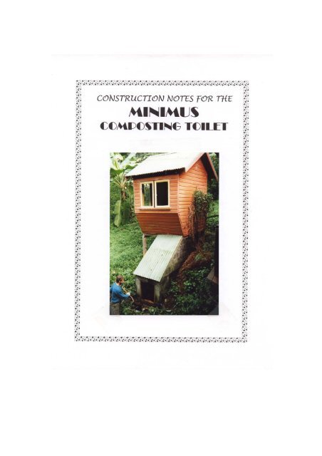
These notes and excerpts are intended to help anyone who wants to build a <strong>Minimus</strong><br />
composting toilet. The basic design of this toilet appears in “Goodbye to the Flush<br />
<strong>Toilet</strong>” (by Carol Hupping Stoner: Rodale, 1977) on page 158.<br />
This publication has been put together to assist those people who are interested in<br />
constructing their own <strong>Minimus</strong> <strong>Compost</strong>ing <strong>Toilet</strong> (MCT)<br />
The original version was put together by Leigh Davison of Southern Cross University<br />
in Lismore, as a result of his experience and the interest shown by others. As a result<br />
of practical experience by a number of people over a number of years I have re-drawn<br />
both Leigh’s plans and the original plans from “Goodbye to the Flush <strong>Toilet</strong>”.<br />
Although there have been no major changes to the original plans, a number of<br />
possible options have been included in the notes. Further additions to the original<br />
document were made by Stuart Downs and Bob Fuller of the International<br />
Development Technologies Centre, Faculty of Engineering, University of Melbourne.<br />
Significant numbers of the <strong>Minimus</strong> composting toilet have been built around<br />
Australia, but particularly in northern N.S.W. A number of these are situated on the<br />
multiple occupancy where Leigh and myself reside and have been operating<br />
successfully for up to 20 years.<br />
It is my intention to continue to update these notes as further innovations and useful<br />
information become known to me. Anyone who uses these plans to construct their<br />
own toilet is invited and encouraged to make suggestions or comments. This way the<br />
design and ease of construction of the <strong>Minimus</strong> will be continually enhanced.<br />
THESE PLANS ARE SUPPLIED ON THE UNDERSTANDING THAT THIS<br />
COMPOSTING TOILET SYSTEM HAS NOT BEEN APPROVED BY THE HEALTH<br />
DEPARTMENT OR ANY OTHER AUTHORITY IN N.S.W.<br />
In N.S.W owner builders may be given conditional approval by local councils to build<br />
a composting toilet. The onus is then on the individual builder to prove that his/her<br />
unit is operating according to Health Dept. guidelines. It is recommended that you<br />
ask your local council for a copy of the state Health Department guidelines for<br />
waterless compost toilets, and any local regulations that may apply and familiarise<br />
yourself with them before submitting an application to build your toilet.<br />
Ray Flanagan<br />
Ross Rd,<br />
The Channon. NSW. 2480<br />
Tel. (02) 6688 6100<br />
E-mail : rayflanagan@nor.com.au
LOCATION<br />
Due to its odour free operation the <strong>Minimus</strong> can be located under the house (2m<br />
clearance needed). For an outhouse, the best location is on a well drained slope with<br />
the back of the chamber dug into the hill.<br />
COST<br />
The total materials cost of the chamber is roughly between $600 and $800 depending<br />
on how good you are at scrounging and recycling materials and which of the various<br />
options you choose (e.g. 100 or 150mm vent pipe). Cost of materials will also vary if<br />
you have to pay transport costs (e.g. delivery of blocks rather than collecting them in<br />
your trailer). Naturally there will be an extra cost involved in providing four walls<br />
and a roof.<br />
CONSTRUCTION SEQUENCE<br />
After selecting the toilet location, the procedure is roughly as follows:<br />
• pour footings<br />
• lay blocks according to arrangements in Figures 2-10, except for baffle wall<br />
• after block layer # 5, backfill, shape and pour internal concrete floor(Fig.12)<br />
• finish external block work including specially cut blocks and holed blocks<br />
• fill in sloping edge of block work to smooth finish with mortar(Figs.15 & 19)<br />
• make and install front access hatch/door (Fig.18)<br />
• cast the slab, for the chamber top, in-situ (or separately, let cure well and install)<br />
• render inside of composting chamber with water-proofing admix e.g. ”Silasec”<br />
(Fig.20)<br />
• lay blocks for baffle wall<br />
• install bypass air ducts(Fig.17)<br />
• if required, paint and plastic external blockwork that will be buried by backfill<br />
• backfill any areas<br />
• construct dunny hut - design it yourself but ensure beautiful view from the<br />
throne!!<br />
• prime composting chamber<br />
ACTIVITIES TO BE UNDERTAKEN CONCURRENTLY WITH CONSTRUCTION<br />
WORK OR PRIOR TO STARTING:<br />
• cut trench mesh and concrete slab reinforcing mesh<br />
• cut holes in blocks to take ½ pipes (Figs 13 &14)<br />
• cut air ducts from PVC pipe<br />
• make front hatch/door (Fig 18)<br />
• make cover for sloping face of unit<br />
3
MATERIALS LIST<br />
If you follow the course layout shown you will need the following (100 x 200 x<br />
400mm) concrete blocks:-<br />
Full Corner ¾ ½ ¼<br />
Standard Chamber 89 20 10 11<br />
Stepped Footing 78 14 10 13<br />
Stepped top 84 29 12 9 2<br />
Fibro Baffles 78 28 10 11<br />
Stepped Footing + Fibro 68 22 12 15<br />
Wide Chamber 101 20 10 15<br />
200 x 200 x 400mm blocks required :- first 3 options above = full x 6, ½ x 2,<br />
wide chamber = full x 9, ½ x 2.<br />
Brickies sand<br />
¼ m3 (about 4 bags)<br />
Blue metal (gravel ) 10mm ½ m3 (order extra for drains)<br />
Sand ( sharp for cementing ) ½ m3<br />
Cement<br />
6 bags<br />
Trench mesh (3 bar F8)<br />
16 metres (extra for step footing)<br />
Slab reinforcing mesh ( F72 ) 1m x 2.5m + 1m x 1m<br />
Stormwater pipe (100mmPVC)<br />
(or 150mm )<br />
1 x 6m (need 4.5m)<br />
Stormwater pipe<br />
(90mm X heavy duty) 3.8m<br />
Galvanised threaded rod (10mm) 1 x 3m length + nuts & washers x 20<br />
Gal. hinges (75 or 100mm option) 2<br />
Gal. steel angle (100 x 100mm) 980mm<br />
Gal. steel angle (5 x 5cm) 980mm<br />
Agricultural pipe (75mm) Approx. 2.5m (if under slab) Extra may<br />
be needed for absorption trench<br />
Building Plastic (optional) Abt. 4sq.m for footings + extra to<br />
lap any sides to be backfilled<br />
Duct tape (optional)<br />
1 roll to join plastic<br />
Silicone sealant<br />
2 tubes<br />
Concrete sealer<br />
1 litre<br />
Corrugated Iron<br />
2 sheets x 1.9m +.8x.7m hatch cover<br />
Formply (humus chamber door)<br />
or 9mm compressed fibro 600 x 800mm<br />
Hardwood - 75 x 38mm)<br />
Or 30 x 30 gal. angle 2.1m (door frame)<br />
Brick ties 10<br />
The approximate concrete volumes are as follows :-<br />
Footings and humus chamber floor 0.63 m3<br />
Sloping floor<br />
0.13 m3<br />
Top slab<br />
0.1 m3<br />
Total<br />
0.85 m3<br />
It is usual to add 10% to the calculated volume if ordering Readymixed concrete.<br />
4
Gravel fill under sloping floor<br />
0.54 m3<br />
CONSTRUCTION HINTS FOR THE MINIMUS<br />
FOOTINGS<br />
Footing dimensions shown are - 300mm wide x 300 deep (the official requirements<br />
vary for different soils), plan dimensions 2600 x 1200mm external, 2000 x 600mm<br />
internal.<br />
In very wet situations , it is recommended to line the footing with heavy duty plastic<br />
and run a length of ag. drain under the floor of the humus chamber to ensure proper<br />
drainage of the soil below the sloping floor of the compost chamber.<br />
On a flat site or when digging into a hillside with a backhoe the footings will be flat.<br />
If digging into a hillside by hand it will be easier to dig a stepped footing as illustrated<br />
in Fig. 2 and Fig. 18. I found, however, that the stepped footing was more time<br />
consuming and the footing itself required more concrete though you will need less<br />
concrete blocks and, of course, less fill material.<br />
Option 1 When excavating for footings and sub-soil drainage you can excavate the<br />
whole area, not just the strips for footings. Backfill sub-soil drains with coarse, clean<br />
gravel. One length of 75mm ag.pipe can be installed under the centre of the toilet<br />
rather than sub-soil drains around the perimeter.<br />
The top edge of the footing formwork was set to the finished footing level all around<br />
to ensure concrete is finished level. Two layers of three bar trench mesh is used in the<br />
footings, blocked up off the trench with pieces of broken concrete or rocks approx.<br />
20mm thick. The concrete is finished to top of formwork and covered overnight.<br />
After stripping the formwork, fill in the central area to top of footing level, holding<br />
plastic to the sides of the footing while filling. I usually pour the flat section of floor,<br />
for humus chamber at the same time as the footing (Fig.11). A number of 10mm steel<br />
reinforcing starter bars, with about 200mm projecting from the slab, can be set into<br />
the footings to allow the blocks to be tied in to the concrete. Threaded starter bars can<br />
be used but are more expensive, however they can be fixed to the set slab using<br />
“Locksins”. I usually place one near each corner to coincide with the holes in the<br />
blocks. Steer clear of the short end of the corner blocks as they are solid. Extra<br />
lengths can be added as you gain height. As the holes are fairly small I fill the blocks,<br />
as I finish each course or 2, with concrete. Use a small aggregate or use a mixture of<br />
“crusher dust “and cement about 6 parts to 1. I only use the steel bars if there is to be<br />
considerable backfill at the back of the chamber.<br />
BLOCK ARRANGEMENT<br />
Details of the most simple block arrangement that works are shown in figures 2<br />
to 6 (narrow chamber), figures 2 and 7 (wide chamber),.Fig.8 (stepped top) and<br />
Fig.9 (baffles)<br />
Lay all the blocks which don’t need cutting, then either a) dry lay the blocks to be cut<br />
on 10mm spacers (mortar thickness) and draw a line on the blocks with a straight<br />
edge, or b) fill the remaining spaces with concrete when finishing the sloping top.<br />
The current block arrangement requires all corner (1¼) blocks at the front of the<br />
chamber, up to course #4. This necessitates the cutting of these blocks on the 2 nd and<br />
4 th courses (except for wide chamber). This is simple with a diamond tipped blade,<br />
but if you don’t have the necessary equipment I suggest you stick with the old layout<br />
which has a chamber 100mm longer (see Figure 10).<br />
5
For a stepped top version the front of the top step (course 9 & 10) can be filled in with<br />
compressed fibre cement or you can brick all the way around, in which case you will<br />
need to use gal. angle for support.<br />
CUTTING CONCRETE BLOCKS<br />
The best way to do this is with a diamond tipped disc on an angle grinder (see Figure<br />
14). Cut along the line to depth of blade. You can use a masonry cutting disc but they<br />
wear out quickly. Cut the blocks, as deep.as your blade will allow, all around. Place<br />
the block on a bed of sand and using a bolster (wide ended masonry chisel)<br />
progressively strike along the line until fracturing occurs. Do not worry if some<br />
chipping occurs, as the sloping edge is rendered with mortar. This will cover many<br />
accidents. However, cutting the bricks is not an easy task, but you will get better at it<br />
the more you do, so persevere and order a few extra blocks to allow for breakage. If<br />
you are able to cut right through the blocks with a diamond tipped disc or masonry<br />
blade on a large circular saw or large grinder the off-cuts can be used to fill in the<br />
small triangular spaces otherwise filled with concrete.<br />
AIR DUCTS<br />
I recommend either 100mm PVC pipe or extra heavy duty 90mm PVC pipe for the<br />
bypass air ducts. Original units used 90mm stormwater pipe, however these have on<br />
occasions proved to have insufficient strength, when halved. It is necessary to make<br />
several holes in eight concrete blocks in the baffle and rear walls of the composting<br />
chamber to accommodate the air duct pipes. One way to do this is to drill a series of<br />
holes around the circumference of the required hole with a masonry bit in a heavy<br />
duty percussion drill (see Figure 13). Once sufficient holes have been drilled, then the<br />
centre of the hole could be removed by breaking through the concrete between the<br />
drilled holes. A pointed chisel and heavy hammer is useful for this. I use a<br />
combination of drilling and cutting with my 100mm angle grinder. I recommend<br />
making the holes a generous size to avoid having to enlarge them when they are in<br />
place. Remember that the vent pipes are inclined at an angle, and therefore the vent<br />
pipe holes in the face of each block are slightly offset. It is important that you don’t<br />
try to put the holes through the web of a block. This will not happen if you adhere to<br />
the block arrangement shown in the plans.<br />
It is necessary to cut two x 1.9m lengths of the PVC pipe lengthwise to create half<br />
pipe channels. These are inserted in the holes in the blocks and span the length of the<br />
chamber. This can be done with a masonry or metal cutting disc on an angle grinder<br />
but a jigsaw does the job with minimal dust. Follow a marked line on both sides of the<br />
pipe and cut one side at a time. A handsaw or circular saw will also do the job.<br />
VENT PIPE<br />
You can use 100mm PVC storm-water pipe for the vent but I recommend 150mm<br />
pipe for more efficient venting. Painting the pipe with black paint will also increase<br />
efficiency. 4m is the recommended length but a longer pipe will draw better. The<br />
pipe is capped with either a “T” junction, or a 90° bend. Silicone a piece of fly wire<br />
to the hole/s. A purpose built “whirly bird” sewer vent is made by Edmonds (Tel.<br />
1800674532) to fit into the flared end of the 150mm pipe or to a 100mm pipe with a<br />
reducer. They are not cheap, but an excellent addition unless in wind protected<br />
situations.<br />
6
BLOCK LAYING<br />
When setting out the wall lines on the footing, allow approx. 100mm between the<br />
blocks and footing edges to ensure blockwork will be centred on the footings. An<br />
easy and accurate method to mark out the corners of the chamber is to place one of the<br />
corner blocks on each corner at the correct distance apart then use a long straight edge<br />
to adjust the blocks so the sides are all square to each other. Details of a block<br />
arrangement that works are shown in Figures 2 to 6 (for narrow chamber) and Figures<br />
2 and 7 (wide chamber. Note - side wall arrangement will be same as for narrow<br />
chamber). These narrow blocks can be quite tricky to lay at first. The blocks should<br />
be level and vertical within themselves and the wall straight and vertical overall. A<br />
string line along the outside wall for each new layer, can be very helpful. Remember<br />
at block course #2 to insert the 100mm x 100mm steel angle to support the baffle wall<br />
(see Figure 2, and 4) and again at course #7 include the 50mmx50mm steel angle to<br />
support the wider, 200mm blocks. I use galvanised angle for longevity. Cut out the<br />
back of the 100mm angle where it will sit over the walls and chip out the blocks<br />
above the angle so they sit down. I temporarily replace the mortar on the inside of the<br />
chamber, where the angle iron sits, with 10mm wooden spacers so that I can slide the<br />
angle iron into position after all the external blockwork is completed. From course 3<br />
remember to embed brick ties in each course where the baffle wall joins. When<br />
placing the blocks with holes, ensure all holes line up and are oriented correctly for<br />
the slope of the air ducts. An alternative to the angle iron supporting the baffle wall<br />
would be a reinforced concrete beam replacing the first block course of the baffle.<br />
10mm threaded rod can be set in the mortar between the 1 st and 2 nd and 3 rd and 4 th<br />
courses at the humus chamber door to take the timber frame. Alternatively the timber<br />
can be fixed later with Dyna bolts. A further option is to make up the door frame first<br />
and tie it in to the blocks with brick wire as you build up the blocks. You could also<br />
set bolts in the mortar, facing outwards so the door could attach directly to the outside<br />
wall. I like to avoid any timberwork inside the chamber, so my current preference is<br />
to use 30 x 30 x 2.5mm galvanised angle attached with hammer drive studs.<br />
A mortar consisting of 1 part portland cement and 3½ parts brick layer’s sand is my<br />
preference. A dash of household detergent added to the water acts as a plasticiser,<br />
making the mortar easier to work and extending it’s working time. The blocks are<br />
made to a length that allows for a 10mm.thick mortar.<br />
POURING THE INTERIOR FLOOR<br />
The interior floor needs to be poured after block layer #4 otherwise access for placing<br />
and finishing concrete would be severely limited. You will need to have the back and<br />
at least one block at the top end of each side of the 5 th course (the top of the sloping<br />
floor finishes on the 5 th course <strong>–</strong> Fig.12). One approach involves the following steps:<br />
• mark line of finished concrete floor level on inside faces of side walls, from<br />
bottom floor level underneath baffle wall to top of block layer #5 at back of unit.<br />
• fill with good, dry material to approx. 75mm below level marked on side wall,<br />
ensure adequate compaction of fill material, fill in approx. 200mm layers and<br />
compact. I use rocks for fill, if available. Depending on fill quality you may want<br />
to provide a layer of gravel on the sloping face between the concrete and fill<br />
material. If so, leave sloping fill material lower by this amount (approx. 30mm)<br />
and place gravel layer prior to concreting. Compact gravel layer adequately. Care<br />
is needed not to disturb any of the block work while compacting fill material.<br />
Allow approx. 20mm between mesh and block walls on each side. Mesh should<br />
7
e raised off sloping fill material prior to concreting as for trench mesh in<br />
footings.<br />
• pour sloping floor and trowel to a smooth finish. Use a dryish mix to avoid<br />
slumping (Fig.12).<br />
• Alternatively the floor could be 15mm compressed fibre cement. Support at the<br />
sides can be provided by fixing gal. angle iron to the blocks.<br />
• A third option is to use 4.5mm standard fibre cement as a temporary support for<br />
the slab. You will need to fix some strips of gal. angle iron into the blockwork to<br />
help support the fibro. These will ultimately support the sides of the suspended<br />
slab. The fibro will need some extra temporary support so it doesn’t collapse<br />
under the weight of the setting concrete. I use 2 lengths of 50 x 25mm timber with<br />
a prop under the middle of each one.<br />
•<br />
UPPER SLAB<br />
The lid of the chamber is usually poured in situ. Holes are formed by a plastic bucket<br />
approx. 300mm diameter or by a 100mm wide strip of flat iron bent into a circle. In<br />
the wide chambered unit two holes are included, located centrally over the gaps<br />
between the three layers of air ducts. By having two holes on this unit both a standard<br />
seat, thunderbox or throne, as well as a squatting hole (for those who prefer this more<br />
effective posture for evacuation) can be provided. When pouring the upper slab don’t<br />
forget to insert a short length of 100 or 150mm PVC pipe in the back corner as a<br />
starter for the vent pipe. Pull this out before the concrete sets so the vent can slip<br />
straight in. The slab should be 10cm thick and reinforced with steel mesh. If casting<br />
the slab separately inserts can be placed around the edges of the slab to allow<br />
connections to the block wall - use PVC pipe of approx. 20mm. If casting the slab in<br />
situ temporary formwork is needed to support the weight until the concrete sets. You<br />
can use plywood, or old corrugated iron, supported with wooden props. The iron can<br />
be cut for a neat, inside, fit and propped in place or cut to overlap the top of the walls<br />
and simply left in situ. Don’t forget to cut holes in the iron or ply for the drop hole<br />
and vent. Wooden boards can be used to form up the sides of the slab. I suggest 125<br />
x 38mm boards with 25mm overlapping the blocks but 50mm thick would be more<br />
rigid. They are nailed together at the ends and propped to the correct height on each<br />
corner. Galvanised bolts (about 10mm) can be set into the edges of the slab to allow<br />
fixing of the hut frame. Alternatively the cured concrete can be drilled to take<br />
masonry fasteners such as “Dynabolts”. If you intend making the room larger than a<br />
metre square the slab could be cantilevered the extra width, however, the overhang<br />
will probably need extra support, such as 100 x 100mm posts, if wider than about<br />
300mm.<br />
FINISHING THE SLOPING EDGES<br />
After the fourth course the front block on each side is beveled as shown in figure 2.<br />
Where this bevel takes out more than half the block length on the side (e.g. on course<br />
7) it is easiest to fill in with cement after all the blocks have been laid. A layer of<br />
concrete up to 2cm deep by 9cm wide (the full block width) is put down on the<br />
sloping edge of the side walls to provide a flat face for the lid of the chamber. A<br />
smooth face is required to ensure a good seal of the cover with the block walls so I<br />
use crusher dust and cement at 6:1 (see Fig.16). A couple of wide floorboards or 100<br />
x 25 boards, clamped to the top of the wall makes a suitable form to pour the concrete<br />
into (Fig.19). Avoid doing this job before the mortar between the blocks has had a<br />
8
chance to set fully. Three or four 8 or 10mm anchor bolts should be set into the<br />
concrete as it starts to set. I usually bend the end of the bolts so that they don’t turn<br />
when the nut is tightened. I clamp the bolt in a vise, slip a 400mm length of iron pipe<br />
over the bolt and bend it with minimal effort. If you finish the sloping edges before<br />
the last course of baffle blocks are laid, then a single form board can be used on the<br />
inside of the chamber wall.<br />
WATERPROOFING<br />
Before back filling any excavated area around the unit, paint blocks and joints that<br />
will be buried with bituminous paint and bring plastic from under footing up the<br />
outside face sticking it against the black paint. Join to plastic from under footing with<br />
good overlap, if necessary, to bring plastic to finished ground level. In very wet areas<br />
lay sub-soil drains around unit at top of footing level to drain water from behind unit.<br />
Lay ag. pipe (unless following Option 1 from “Footings”) and backfill with well<br />
draining gravel material and good soil. To waterproof the chamber and to cover any<br />
cracks and joins plaster internal surfaces with a cement render containing 6 parts fine<br />
sand*, 1 part lime and 1 part cement plus “Silasec” or similar waterproofing as per<br />
manufacturer’s recommendations. Make the mix quite wet so it is easy to apply thinly<br />
You don’t need to do the baffle. One of the main enemies of aerobic conditions is<br />
moisture, therefore, ingress of water is a potential problem to the unit operation that<br />
should be avoided (see Fig20).<br />
*Brickie’s or river sand can be used if sieved.<br />
HUMUS CHAMBER DOOR<br />
Make the door from either formply (used for concreting) or 9 or 12mm compressed<br />
fibro. Cover vent hole with fly wire and overlay with rat wire (see Fig.18). Fix frame<br />
to blockwork. The hatch can be either a lift off or hinged door. To seal the door I use<br />
20mm strips of foam (as used in concrete expansion joints). I ‘glue’ it to the plywood<br />
using silicone sealant. Or run a bead of silicone around the edges of the door before<br />
bolting it to the frame. I smear a thin coat of grease to the doorframe so the silicone<br />
only adheres to the door. If using the gal. angle frame (see Block Laying) I attach the<br />
door using 8mm cup head bolts. Drill 2 x 8mm holes in both of the side angle irons,<br />
use a small 3 cornered file to shape holes into a square to accept the bolts. Next glue<br />
the bolt head into the hole using a strong glue such as Araldite<br />
LIQUID DRAIN<br />
The installation of an excess liquids drain from the humus chamber near the<br />
hatch/door is necessary. This excess liquid (leachate) can be directed to either a grey<br />
water system or an absorption trench*. The drain shown in Fig.1 exits horizontally at<br />
floor level. Some form of screen will be needed to prevent the humus from blocking<br />
this pipe. A slight fall towards the drain hole can be built into the humus chamber<br />
floor when floating the concrete. The drain could also exit vertically but would have<br />
to be set in place before pouring the floor. If you don’t want to dig it under the footing<br />
it could be installed through (and at the same time as) the footing. A 50mm (or<br />
larger) bathroom waste drain suits this application. A simple filter (example below)<br />
will help prevent blockage of the drain.<br />
(* A trench 2m x 300 wide x 400mm deep should suffice. Line the bottom of the<br />
trench with 100mm of course gravel, lay 75mm diameter agricultural drain or 90mm<br />
slotted PVC pipe in the trench. Seal off the ends of the ag. drain and cut a hole in it to<br />
9
accept the PVC drain pipe. Fill the drain with gravel, to within 100mm of the ground<br />
level, cover with ‘geofabric’ and top up the trench with soil.)<br />
WASTE WATER FILTER DETAIL<br />
PVC pipe (100 or 90mm)<br />
abt.10cm<br />
Slits cut with angle grinder<br />
using a metal-grinding disc<br />
Not to scale<br />
PRIMING THE UNIT<br />
It is easiest to “prime” the composting chamber before the corrugated iron “lid” is<br />
fixed into place. A bale of straw is laid evenly on the sloping floor of the chamber. A<br />
bucket or so of compost is then added onto the top of the straw.<br />
FITTING THE SLOPING CHAMBER COVER<br />
The lid can be screwed or nailed onto timber battens which are themselves secured to<br />
the block work by the anchor bolts (see Fig.16). I usually bolt the iron directly onto<br />
the cement. You may need to have some support for the iron at the top end of the<br />
chamber, such as a couple of right angle brackets fixed into the squat slab. I find if I<br />
cut the iron to be a snug fit and bend the valleys up with pliers it will be supported<br />
against the slab. Gaps and chinks around the lid can be filled in with mortar. A hole<br />
has to be cut in the iron for an inspection opening. I favour putting it to one side, but<br />
it can be centred. A hole about 600mm long and 300 to 400mm wide should allow<br />
sufficient access to rake the compost heap. A sheet of corrugated iron about 1m long<br />
is used as a cover. This can be attached to the fixed iron with stainless steel selftapping<br />
screws. I fix a length of flashing about 250mm wide to the slab or upstairs<br />
cladding. This covers the top of the inspection cover and can be fixed down using the<br />
two upper fixing bolts for the iron roof.<br />
OTHER STEPS<br />
• ensure all joints are well sealed e.g. around access hatch, between hatch and cover,<br />
cover to block wall, cover to concrete slab - to ensure unit is insect-proof<br />
• make dunny hut - design to suit yourself but ensure you have a beautiful view<br />
from the throne!<br />
OTHER OPTIONS<br />
• The hole in the squat slab can vary according to whether a squat plate or pedestal<br />
is planned. If a pedestal is favoured I suggest a larger chute, preferably sloping<br />
away from the seat. This will help avoid unnecessary soiling of the sides. The<br />
plans show a 30cm hole which would be too large for a comfortable squat hole. In<br />
fact a more elongated hole would be more suitable for squatting.<br />
• The vent pipe can be centred on the squat plate rather than offset as in the plans.<br />
10
• If the chamber is to be installed under an existing, dry, floor there is no necessity<br />
for a sloping lid to the chamber. In this case the top can be stepped so no cutting<br />
is required (see Fig.8 & 9). It is also wise in this case to have a metal (preferably<br />
stainless steel) or plastic chute to connect the chamber and floor. A direct<br />
connection between the blocks and a timber floor is an invitation to termites. The<br />
top could be sealed with moisture proof compressed cement sheeting with holes<br />
cut out for the chute and the vent pipe. Likewise the inspection cover and top of<br />
the humus chamber could also be compressed cement sheeting. The top cover can<br />
be bolted down or hinged for easy removal but the top of the humus chamber can<br />
be fixed more permanently. A bead of silicone sealant around the edge of each<br />
cover, before fixing, will ensure a fly proof seal. Depending on the thickness of<br />
‘fibro’ used you may need to attach some strips of wood, on the outside, (say 20 x<br />
75mm) for stiffening. You will need to install an extra length of steel angle to<br />
support the extra blocks above the doorway or, alternatively, make the door longer<br />
so that it still goes to the top of the humus chamber. You can close in the front of<br />
the top step with blocks, in which case you will need to insert another length of<br />
angle iron for support. The alternative is to simply attach a piece of compressed<br />
fibre cement sheeting. You will need to cut 1 or 2 holes (about 50 x 50mm) in the<br />
top course of the baffle wall (or in the inspection cover) to allow air to flow up<br />
over the top of the compost heap. N.B. Standard fibre cement should not be used<br />
as it will become brittle.<br />
• You may also get away with shallower footings if the blocks are not supporting<br />
the ‘throne room’.<br />
11
MANAGEMENT OF YOUR MINIMUS<br />
COMPOSTING TOILET<br />
ROUTINE MAINTENANCE<br />
The chamber can receive excrement, household wastes and additional high carbon<br />
content organic matter. After a minimum of 9 months the first compost can be<br />
removed, via the door of the humus chamber and the compost used in the orchard or<br />
flower garden in accordance with health regulations. As an added factor of safety we<br />
recommend not using the compost directly in the vegetable garden. Should the<br />
composting pile become too close to the top of the chamber it will be necessary to<br />
knock the top off the pile with a suitable stick. This can be done by removing the<br />
inspection cover on the chamber lid or possibly through the drop chute.<br />
The frequency of removal of composted matter will vary according to the volume of<br />
raw material entering the chamber, but is usually between 3 and 6 months. It is<br />
important to not let the humus build up too high as this can interfere with it’s further<br />
downhill movement. If the humus is not feeding into the lower chamber it may be<br />
necessary to slide a small shovel or other suitable implement under the baffle wall to<br />
free up the pile.<br />
THEORY AND PRACTICE OF OPERATION<br />
Aeration:<br />
Aerobic bacteria live only in the presence of oxygen. To ensure good aeration from<br />
the start, place at least 300mm of loose, dry straw or grass over the bottom of the<br />
chamber. Aeration is supplied by air flowing through the vents, over the pile and up<br />
the flue.<br />
Adding worms:<br />
<strong>Compost</strong>ing worms, such as Red Wrigglers or Tiger Worms, can be added to the<br />
chamber, however, this can make the compost very heavy and dense and therefore<br />
tend to restrict the down hill movement.<br />
Moisture content:<br />
The ideal aerobic compost pile is moist but not wet, fluffy and loose, not dense and<br />
matted. Since faeces are 65-80% moisture, light dry material such as dry leaves,<br />
wood shavings, sawdust, chopped dry grass, straw, wood chips or shredded or<br />
screwed-up newspaper must be added after each use to keep the pile from becoming<br />
too wet. If you live in a bush setting it may be possible to urinate outside the privy to<br />
avoid the pile becoming too wet. If you do urinate in the toilet, or when adding moist<br />
kitchen scraps, it is important to add some of the above mentioned dry bulking<br />
material. Use of fine sawdust tends to clog the system and prevents the composted<br />
material from feeding through to the humus chamber.<br />
Nitrogen ratio<br />
Organic material contains varying amounts of carbon and nitrogen. Faeces contain<br />
about 6% nitrogen, urine 15-18%. The optimum environment for the microorganisms<br />
decomposing the pile is 30 parts of Carbon to each part of Nitrogen. Too much<br />
nitrogen or other absorbent organic material slows or changes the process. Throw in a<br />
500gm. coffee can of wood shavings, or equivalent amount of other bulking material,<br />
after each use of the privy.<br />
12
CALCULATIONS<br />
Faeces should constitute no more than 20-25% of the composting material. Human<br />
waste per person per day averages 225 gm faeces (moist weight) plus 3 litres urine. A<br />
yearly average equals about 145 kg faeces, 0.2 m3 urine. At 22 kg/litre and 1,100<br />
litres/cubic metre, this equals 0.08 m3. faeces, 0.2 m3. urine. Decomposition reduces<br />
this raw wet volume to one twentieth its original volume. (We use 30,000 - 40,000<br />
litres of water per person per year to flush<br />
Excreta cannot be accessible to insects or animals or children.<br />
The concrete design is impervious to penetration by pests. Insect screening at the<br />
vents prevents flies from entering. If the privy is freestanding from the house, it<br />
should be provided with a screen door. The main insect problem is flies, which<br />
can pass through a 3mm crack. Flies are attracted by smell and seek light.<br />
Sprinkling sawdust on fresh material, and of course, keeping the lid or cover<br />
down when the privy is not in use will prevent any fly nuisance. If you are<br />
adding kitchen scraps make sure you take all precautions to exclude insects from<br />
scraps prior to their addition to the toilet. Should fly infestation occur hydrated<br />
lime or wood ash can be sprinkled on the surface of the pile regularly,<br />
concentrating on areas where the larvae are most active, until the flies are<br />
eliminated. Alternatively, spray the flies and larvae with pyrethrum. Cockroaches<br />
can also be treated with pyrethrum but their entry to the chamber should not be<br />
possible if the chamber is properly sealed. Normal compost pile insects such as<br />
“slaters” are quite O.K. and shouldn’t pose a health problem<br />
There should be no noticeable odour or unsightly conditions.<br />
There will be no odour if the design and operating instructions are followed<br />
carefully. Make sure the cover fits tight and the vent is unobstructed. If odour<br />
becomes noticeable it is due to one or more of the following reasons:-<br />
• Wrong proportions of materials, unable to maintain hot temperatures<br />
• Too wet (add more dry sawdust or straw , check liquid drain hole for any<br />
blockage)<br />
• Too high nitrogen (add more sawdust or straw, high C/N material - too much<br />
nitrogen smells like ammonia.)<br />
Construction must be durable.<br />
The concrete provides a tight, sealed chamber, impervious to weather, bacterial<br />
action and other conditions.<br />
Finished material must be free from pathogens and safe to build the soil.<br />
Laboratory and field experiments confirm that pathogens cannot survive the<br />
normally high temperatures of aerobic composting, nor do they survive very long<br />
in material that is allowed to age. Proper composting and lengthy exposure to the<br />
elements are the cornerstones to purification. Beyond this, only sterilizing all<br />
finished material with heat to kill all microorganisms, good and bad, can<br />
guarantee complete safety.<br />
13
PVC cap with<br />
fly screen<br />
Vent pipe - 100 or 150mmdia.<br />
PVC 4mlong, fly screen at top<br />
Use 200mm<br />
hollow blocks<br />
to make baffle<br />
90 or 100mmØ<br />
PVC air duct<br />
4m<br />
100mmhollow<br />
blocks<br />
75mmconcrete<br />
slab on fill,<br />
30º slope<br />
Ventilation Pipe<br />
100<br />
800<br />
600<br />
Wooden access door<br />
END VIEW<br />
Optional<br />
Pedestal<br />
Air ducts<br />
Squat plate<br />
SECTION B-B<br />
Vent hole 100x250 with fly screen<br />
Access lid/inspection cover<br />
Footing 300x300<br />
All Dimensions Shown in Millimetres<br />
Access door for removal of organic matter<br />
Reinforced, formed<br />
concrete beam<br />
900<br />
700<br />
2m<br />
100<br />
900<br />
300<br />
FIG. 1<br />
SECTION A-A<br />
Liquid drain to greywater system<br />
or absorption trench<br />
Clivus Plans Adapted From Rybczynski's Variation on the Clivus Multrum<br />
( Page 158 of "Goodbye to the Flush <strong>Toilet</strong>")<br />
14
FIG. 1a<br />
PLAN VIEW "A"<br />
150<br />
100 or 150mmdia. hole for vent (can be placed<br />
anywhere on slab but preferably along back wall)<br />
350<br />
500<br />
100x100x10<br />
R.C.Slab<br />
150<br />
350<br />
500<br />
Corrugated G.I. sheet painted<br />
black. Use G.I. anchor bolts<br />
PLAN VIEW "B"<br />
B<br />
90<br />
A<br />
500<br />
500<br />
300<br />
1m<br />
1m<br />
300<br />
200 200<br />
<strong>Compost</strong>ing Chamber<br />
Humus<br />
Chamber<br />
Liquid<br />
Drain<br />
620<br />
1m<br />
820<br />
A<br />
90<br />
B<br />
90<br />
1.62m<br />
2.4m<br />
510<br />
90<br />
100<br />
15
FIG. 2<br />
3/4<br />
STANDARD BLOCK ARRANGEMENT<br />
1m<br />
3/4<br />
10<br />
9<br />
8<br />
7<br />
6<br />
6 x 125mm bolts<br />
grouted in<br />
Cement fill<br />
Baffle wall<br />
Reinforced<br />
conc. lintel<br />
3/4<br />
3/4<br />
5<br />
4<br />
3/4 3/4<br />
3<br />
2<br />
1<br />
Corner (1 1/4 ) blocks<br />
100x100 steel angle<br />
Heavy line = line of stepped footing<br />
10<br />
9<br />
8<br />
7<br />
50x50mm steel<br />
angle to<br />
support front<br />
end of 200mm<br />
blocks<br />
6<br />
5<br />
4<br />
3<br />
Concrete lintel<br />
38mm x 75<br />
h/w framing<br />
2<br />
1<br />
Concrete floor<br />
Substitute 1/2 & 3/4 blocks here for stepped footing<br />
2.4m<br />
620<br />
Conc. curb<br />
16
FIG. 3<br />
COURSE 1 & 3, NARROW CHAMBER<br />
1 1/4<br />
1 1/4<br />
1/2<br />
1 1/4 1 1/4<br />
FIG. 4<br />
COURSES 2 & 4, NARROW CHAMBER<br />
1 1/4<br />
1 1/4<br />
3/4<br />
3/4<br />
Angle iron back cut out<br />
where it sits on blocks<br />
1 1/4<br />
2.4m<br />
1 1/4<br />
FIG. 5<br />
COURSE 5 FOR NARROW CHAMBER<br />
(2 1/2 blocks wide)<br />
Conc. Lintel<br />
1 1/4<br />
1m<br />
1/2<br />
1/2 3/4<br />
Air ducts centre line<br />
3/4<br />
90<br />
400<br />
210<br />
1 1/4<br />
Break hole in inside of end blocks<br />
to key into concrete lintel<br />
17
FIG. 6<br />
BLOCK ARRANGEMENT FOR COURSE 7,<br />
NARROW CHAMBER<br />
Walls joined<br />
with brick ties<br />
1/2<br />
FIG. 7<br />
COURSE 1 FOR WIDE CHAMBER<br />
1.4m<br />
1 1/4 1/2<br />
1 1/4<br />
21<br />
21<br />
400<br />
400<br />
90<br />
1 1/4 1 1/4<br />
Air duct centre line<br />
2.4m<br />
18
FIG.8<br />
BLOCK ARRANGEMENT FOR STEPPED TOP<br />
10<br />
9<br />
8<br />
7<br />
6<br />
5<br />
4<br />
3<br />
2<br />
1<br />
1/2<br />
1/4 1/4<br />
3/4 3/4<br />
1/2<br />
Flat or<br />
angled<br />
steel<br />
Concrete floor<br />
2.4m<br />
Conc.<br />
curb<br />
620<br />
FIG. 9<br />
BLOCK ARRANGEMENT FOR BAFFLES<br />
Standard Chamber<br />
1/2<br />
1/4 1/4<br />
Step Top<br />
1/2<br />
Wide Chamber<br />
1/2<br />
1/2 3/4 3/4<br />
3/4 1/2 3/4<br />
3/4 1/2<br />
3/4<br />
3/4 1/2 3/4<br />
19
FIG.10<br />
OLD BLOCK ARRANGEMENT<br />
(use when you don't want to cut front corner blocks)<br />
10<br />
9<br />
8<br />
7<br />
6<br />
5<br />
4<br />
3<br />
2<br />
1<br />
1m<br />
6 x 125mm bolts<br />
grouted in<br />
Cement fill<br />
Baffle wall<br />
3/4<br />
3/4<br />
3/4<br />
Reinforced<br />
conc. lintel<br />
3/4<br />
100x100 steel angle<br />
Heavy line = line of stepped footing<br />
2.5m<br />
All (1 1/4) corner<br />
blocks shaded<br />
For rear wall layout see FIG.2<br />
20