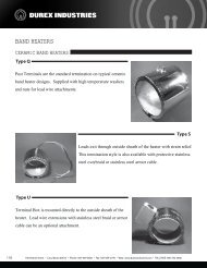
RB Series Specification Sheet - Durex Industries
RB Series Specification Sheet - Durex Industries
RB Series Specification Sheet - Durex Industries

Create successful ePaper yourself
Turn your PDF publications into a flip-book with our unique Google optimized e-Paper software.
4<br />
4<br />
Input<br />
Input<br />
<strong>Specification</strong>s<br />
<strong>Specification</strong>s<br />
Control<br />
Control<br />
Input<br />
a) Temperature input group<br />
Control method PID control (With autotuning)<br />
Input<br />
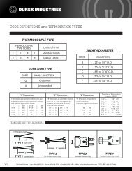
a) Temperature Thermocouple input : K, group J, E, T, R, S, B, N (JIS/IEC)<br />
Control method PID • P, control PI, PD, (With ON/OFF autotuning) control selectable<br />
Thermocouple : K, PLII J, (NBS), E, T, R, W5Re/W26Re S, B, N (JIS/IEC) (ASTM)<br />
• P, Direct PI, PD, action/Reverse ON/OFF control action selectable is selectable<br />
RTD : Pt100 (JIS/IEC), PLII (NBS), JPt100 W5Re/W26Re (JIS) (ASTM)<br />
Heat/Cool • Direct action/Reverse type PID control action (With is selectable autotuning)<br />
RTD • 3-wire : Pt100 system (JIS/IEC), JPt100 (JIS)<br />
Startup tuning Heat/Cool The condition type to PID activate control Startup (With Tuning autotuning) is selectable<br />
b) Voltage/Current • 3-wire system input group<br />
Startup tuning The among condition a) to g) to activate Startup Tuning is selectable<br />
b) Voltage/Current Voltage input (Input input group impedance : Approx.1MΩ)<br />
among a) At power-on a) to g) and stop-to-run, one-time tuning<br />
Voltage 0 to 1V input DC, 0 (Input to 5V impedance DC, 1 to 5V DC, : Approx.1MΩ)<br />
0 to 10V DC<br />
a) b) At power-on SV change, and one-time stop-to-run, tuning one-time tuning<br />
Current 0 to 1V input DC, (Input 0 to 5V impedance DC, 1 to 5V : DC, 250Ω) 0 to 10V DC<br />
b) c) At power-on, SV change, stop-to-run one-time tuning and SV change, one-time tuning<br />
Current 4 to 20mA, input 0 (Input to 20mA impedance : 250Ω)<br />
c) d) At power-on, every power-on stop-to-run and stop-to-run and SV change, one-time tuning<br />
• For current 4 to 20mA, input, 0 connect to 20mAis<br />
a 250Ω shunt resistor to<br />
d) e) At every power-on SV changeand<br />
stop-to-run<br />
• the For input current terminals. input, connect Model code is a 250Ω : KD100-55 shunt resistor to<br />
e) f) At every power-on, SV changestop-to-run<br />
and SV change<br />
• the Inputs input is selectable terminals. Model within each code group. : KD100-55<br />
f) g) At Function every power-on, off stop-to-run and SV change<br />
Input break action • Thermocouple Inputs is selectable input : within Up-scale/Down-scale each group. (Selectable)<br />
Fine tuning Setting g) Function range off : -3 to +3 (6 levels, OFF when set to 0.)<br />
Input break action Thermocouple RTD input : input : Up-scale/Down-scale Up-scale<br />
(Selectable)<br />
Fine tuning Setting -3 to -1 range : Faster : -3 response<br />
RTD Voltage input input : : Value Up-scale around 0V<br />
to +3 (6 levels, OFF when set to 0.)<br />
-3 1 to to 3 -1 : : Slower Faster response<br />
Voltage Current input : Value around 0mA 0V<br />
Input short action Current Down-scale input (RTD : input)<br />
1 OFF to 3 : : Slower Function response OFF<br />
Value around 0mA<br />
Input Sampling short time<br />
Setting range a)<br />
action Down-scale (RTD input)<br />
OFF Proportional : Function band OFF :<br />
0.25sec<br />
Sampling time<br />
Setting range a) Proportional Temperature band input : : 1(0.1) to span (°C,°F)<br />
Influence of external 0.25sec 0.25µV/Ω (Thermocouple input)<br />
Temperature • When 0.1°C input (°F) resolution, : 1(0.1) to span within (°C,°F) 999.9°C (°F)<br />
Influence resistanceof<br />
external 0.25µV/Ω (Thermocouple input)<br />
• Voltage/Current When 0.1°C (°F) input resolution, : 0.1 to 100.0% within 999.9°C of span<br />
resistance Influence of lead 0.02% of reading/Ω (RTD input)<br />
(°F)<br />
Voltage/Current (ON/OFF control input when : 0.1 P = to 0)<br />
Influence resistanceof<br />
lead 0.02% • Maximum of reading/Ω 10Ω (RTD per wire<br />
100.0% of span<br />
input)<br />
• (ON/OFF Differential control gap at ON/OFF when P control = 0)<br />
PV resistance bias Temperature • Maximum input 10Ω : -1999(-199.9) per wire to +9999(999/9)°C<br />
• Differential (High/Low gap individual at ON/OFF setting) control :<br />
PV bias Temperature Voltage/Current input input : -1999(-199.9) : -span to +span to +9999(999/9)°C<br />
Temperature (High/Low individual input : 0(0.0) setting) to 100 : (100.0) (°C,°F)<br />
Input digital filter Voltage/Current 0.1 to 100.0 sec. input (OFF : -span when 0 to is +span set.)<br />
Temperature Voltage/Current input input : 0(0.0) : 0.0 to 100 10.0% (100.0) of span (°C,°F)<br />
Input digital filter 0.1 to 100.0 sec. (OFF when 0 is set.)<br />
b) Integral Voltage/Current time : 1 to input 3600 : 0.0 sec to (PD 10.0% control of span when I = 0)<br />
b) c) Derivative Integral time time : 1 : to 1 to 3600 3600 sec sec (PD (PI control when I = D 0) = 0)<br />
Display<br />
c) d) Derivative Cool side proportional time : 1 to 3600 band sec : (PI control when D = 0)<br />
Display<br />
Display method PV : 11 segment (4 digits), SV : 7 segments (4 digits)<br />
d) Cool 1 to side 1000% proportional of heat side band proportional : band<br />
Display method PV LCD : 11 display segment (4 digits), SV : 7 segments (4 digits)<br />
1 * Invalidity to 1000% when of heat P=0. side proportional band<br />
LCD display<br />
* Invalidity Only cooling when side P=0. ON/OFF control is not available.<br />
e) Anti-Reset * Only cooling Windup(ARW) side ON/OFF : control is not available.<br />
Performance<br />
e) Anti-Reset 1 to 100% Windup(ARW) of heat side proportional : band<br />
Measuring Performance<br />
accuracy See measuring accuracy code table<br />
1 (Integral to 100% action of heat is OFF side when proportional ARW = band 0)<br />
Measuring Influence of accuracy ambient See Temperature measuring input accuracy : ±0.06°C/°C code table [at 5 to 40°C]<br />
f) Deadband/Overlap<br />
(Integral action is OFF when ARW = 0)<br />
Influence temperature of ambient Temperature Voltage/Current input input : ±0.06°C/°C group : ±0.06% [at 5 of to span/°C 40°C] [at 5 to 40°C]<br />
f) Deadband/Overlap<br />
Temperature input : -10 (-10.0) to 10 (10.0) °C (°F)<br />
temperature<br />
Close horizontal Voltage/Current input group : ±0.06% of span/°C [at 5 to 40°C]<br />
Temperature Voltage/Current input input : -10 : -10.0 (-10.0) to to +10.0% 10 (10.0) of span<br />
±2°C (3.6°F) [Less than -100°C (-146°F) input : ±3.5°C (6.3°F)]<br />
°C (°F)<br />
Close mounting horizontal error<br />
Voltage/Current • Minus setting input : Overlap : -10.0 to +10.0% of span<br />
±2°C (3.6°F) [Less than -100°C (-146°F) input : ±3.5°C (6.3°F)]<br />
Insulation mounting resistance error More than 20MΩ (500V DC) between measured terminals<br />
g) Derivative • Minus setting time action : Overlap select<br />
Insulation resistance More and ground than 20MΩ (500V DC) between measured terminals<br />
g) Derivative 0 : PV derivative, time action 1 : select Deviation derivative<br />
and More ground than 20MΩ (500V DC) between power terminals and<br />
h) Output 0 : PV limiter derivative, 1 : Deviation derivative<br />
More ground than 20MΩ (500V DC) between power terminals and<br />
h) Output PID control limiter : -5.0 to +105.0%<br />
ground<br />
PID control : (High/Low -5.0 to +105.0% individual setting)<br />
Dielectric voltage 1000V AC for 1 minute between measured terminals and ground<br />
Heat/Cool type (High/Low PID control individual : setting)<br />
Dielectric voltage 1000V 1500V AC for 1 minute between measured power terminals terminals and and ground ground<br />
Heat/Cool type 0.0 PID to 105.0% control (Only : limiter high)<br />
1500V AC for 1 minute between power terminals and ground<br />
(Heat 0.0 to side/Cool 105.0% (Only side individual limiter high) setting)<br />
Setting<br />
i) Proportional cycle (Heat time side/Cool : side individual setting)<br />
Setting<br />
i) Proportional 0.1sec, 0.25sec, cycle time 0.5sec, : 1 to 100 sec<br />
SV limiter Scaling low to scaling high (High/Low individual setting<br />
j) Heat/Cool 0.1sec, 0.25sec, PID control 0.5sec, selection 1 to 100 : sec<br />
SV limiter Scaling low to scaling high (High/Low individual setting<br />
j) Heat/Cool Air cooling, PID Water control cooling, selection Linear<br />
Ramp-to-setpoint 1(0.1) to span per Time (Time : 1 minute/1 hour (Selectable)<br />
:<br />
Air cooling, Water cooling, Linear<br />
Ramp-to-setpoint 1(0.1) Up/Down to span individual per Time setting (Time : 1 minute/1 hour (Selectable) Manual output a) Output range<br />
SV step function Number Up/Down of individual SV : 4 points setting (Default : 1 point)<br />
Manual output a) Output PID control range : Output limiter low to Output limiter high<br />
SV step function Number SV selecting of SV method : 4 points : Front (Default key, : Communication,<br />
1 point)<br />
PID Heat/Cool control type : Output PID control limiter low : to Output limiter high<br />
SV selecting method : Digital Front key, input Communication,<br />
(External contact input)<br />
Heat/Cool -(Cool side type output PID control limiter high) : to<br />
Timer function Timer setting : 0 min 01 sec Digital to 99 input min 59 (External sec or contact input)<br />
-(Cool (Heat side output limiter high) to<br />
Timer function Timer setting : 0 min hr 01 01 min sec to to 99 99 hr min 59 59 min sec (selectable)<br />
b) Auto/Manual<br />
or<br />
(Heat side transfer output action limiter high) selection<br />
Function 0 hr 01 min to 99 hr 59 min (selectable)<br />
b) Auto/Manual With bumpless/Without transfer action bumpless selection (Selectable)<br />
Function 1: Control starts after the timer time elapses.<br />
Control output a) Relay<br />
With bumpless/Without<br />
contact output, Form<br />
bumpless<br />
a contact,<br />
(Selectable)<br />
250V AC 3A<br />
1: 2: Control starts is performed after the during timer the time timer elapses. time and stops after the timer Control output a) Relay (Resistive contact load) output, Form a contact, 250V AC 3A<br />
2: time Control elapses. is performed during the timer time and stops after the timer<br />
(Resistive • Electric life load) : 1,000,000 cycles or more<br />
3:Link time function elapses. from SV1 to SV4<br />
b) Voltage • Electric pulse life : output, 1,000,000 0/12V cycles DC or more<br />
3:Link (After function the timer from time SV1 elapses, to SV4 control is continued using SV4.)<br />
b) Voltage (Load resistance pulse output, : more 0/12V than DC600Ω<br />
)<br />
4:Link (After function the timer from time SV1 elapses, to SV4 control is continued using SV4.)<br />
• (Load When resistance out2 is no : use, more load than resistance 600Ω ) than<br />
4:Link (After function the timer from time SV1 elapses, to SV4 control is stopped.)<br />
• 300Ω When . use, load resistance is more than<br />
Repeat (After the : 0 to timer 9999 time (Continuous elapses, control when when is stopped.) 9999 is set.)<br />
See 300Ω page