RB Series Specification Sheet - Durex Industries
RB Series Specification Sheet - Durex Industries
RB Series Specification Sheet - Durex Industries

Create successful ePaper yourself
Turn your PDF publications into a flip-book with our unique Google optimized e-Paper software.
Process and Temperature Controllers<br />
www.durexindustries.com
4<br />
4<br />
Input<br />
Input<br />
<strong>Specification</strong>s<br />
<strong>Specification</strong>s<br />
Control<br />
Control<br />
Input<br />
a) Temperature input group<br />
Control method PID control (With autotuning)<br />
Input<br />
a) Temperature Thermocouple input : K, group J, E, T, R, S, B, N (JIS/IEC)<br />
Control method PID • P, control PI, PD, (With ON/OFF autotuning) control selectable<br />
Thermocouple : K, PLII J, (NBS), E, T, R, W5Re/W26Re S, B, N (JIS/IEC) (ASTM)<br />
• P, Direct PI, PD, action/Reverse ON/OFF control action selectable is selectable<br />
RTD : Pt100 (JIS/IEC), PLII (NBS), JPt100 W5Re/W26Re (JIS) (ASTM)<br />
Heat/Cool • Direct action/Reverse type PID control action (With is selectable autotuning)<br />
RTD • 3-wire : Pt100 system (JIS/IEC), JPt100 (JIS)<br />
Startup tuning Heat/Cool The condition type to PID activate control Startup (With Tuning autotuning) is selectable<br />
b) Voltage/Current • 3-wire system input group<br />
Startup tuning The among condition a) to g) to activate Startup Tuning is selectable<br />
b) Voltage/Current Voltage input (Input input group impedance : Approx.1MΩ)<br />
among a) At power-on a) to g) and stop-to-run, one-time tuning<br />
Voltage 0 to 1V input DC, 0 (Input to 5V impedance DC, 1 to 5V DC, : Approx.1MΩ)<br />
0 to 10V DC<br />
a) b) At power-on SV change, and one-time stop-to-run, tuning one-time tuning<br />
Current 0 to 1V input DC, (Input 0 to 5V impedance DC, 1 to 5V : DC, 250Ω) 0 to 10V DC<br />
b) c) At power-on, SV change, stop-to-run one-time tuning and SV change, one-time tuning<br />
Current 4 to 20mA, input 0 (Input to 20mA impedance : 250Ω)<br />
c) d) At power-on, every power-on stop-to-run and stop-to-run and SV change, one-time tuning<br />
• For current 4 to 20mA, input, 0 connect to 20mAis<br />
a 250Ω shunt resistor to<br />
d) e) At every power-on SV changeand<br />
stop-to-run<br />
• the For input current terminals. input, connect Model code is a 250Ω : KD100-55 shunt resistor to<br />
e) f) At every power-on, SV changestop-to-run<br />
and SV change<br />
• the Inputs input is selectable terminals. Model within each code group. : KD100-55<br />
f) g) At Function every power-on, off stop-to-run and SV change<br />
Input break action • Thermocouple Inputs is selectable input : within Up-scale/Down-scale each group. (Selectable)<br />
Fine tuning Setting g) Function range off : -3 to +3 (6 levels, OFF when set to 0.)<br />
Input break action Thermocouple RTD input : input : Up-scale/Down-scale Up-scale<br />
(Selectable)<br />
Fine tuning Setting -3 to -1 range : Faster : -3 response<br />
RTD Voltage input input : : Value Up-scale around 0V<br />
to +3 (6 levels, OFF when set to 0.)<br />
-3 1 to to 3 -1 : : Slower Faster response<br />
Voltage Current input : Value around 0mA 0V<br />
Input short action Current Down-scale input (RTD : input)<br />
1 OFF to 3 : : Slower Function response OFF<br />
Value around 0mA<br />
Input Sampling short time<br />
Setting range a)<br />
action Down-scale (RTD input)<br />
OFF Proportional : Function band OFF :<br />
0.25sec<br />
Sampling time<br />
Setting range a) Proportional Temperature band input : : 1(0.1) to span (°C,°F)<br />
Influence of external 0.25sec 0.25µV/Ω (Thermocouple input)<br />
Temperature • When 0.1°C input (°F) resolution, : 1(0.1) to span within (°C,°F) 999.9°C (°F)<br />
Influence resistanceof<br />
external 0.25µV/Ω (Thermocouple input)<br />
• Voltage/Current When 0.1°C (°F) input resolution, : 0.1 to 100.0% within 999.9°C of span<br />
resistance Influence of lead 0.02% of reading/Ω (RTD input)<br />
(°F)<br />
Voltage/Current (ON/OFF control input when : 0.1 P = to 0)<br />
Influence resistanceof<br />
lead 0.02% • Maximum of reading/Ω 10Ω (RTD per wire<br />
100.0% of span<br />
input)<br />
• (ON/OFF Differential control gap at ON/OFF when P control = 0)<br />
PV resistance bias Temperature • Maximum input 10Ω : -1999(-199.9) per wire to +9999(999/9)°C<br />
• Differential (High/Low gap individual at ON/OFF setting) control :<br />
PV bias Temperature Voltage/Current input input : -1999(-199.9) : -span to +span to +9999(999/9)°C<br />
Temperature (High/Low individual input : 0(0.0) setting) to 100 : (100.0) (°C,°F)<br />
Input digital filter Voltage/Current 0.1 to 100.0 sec. input (OFF : -span when 0 to is +span set.)<br />
Temperature Voltage/Current input input : 0(0.0) : 0.0 to 100 10.0% (100.0) of span (°C,°F)<br />
Input digital filter 0.1 to 100.0 sec. (OFF when 0 is set.)<br />
b) Integral Voltage/Current time : 1 to input 3600 : 0.0 sec to (PD 10.0% control of span when I = 0)<br />
b) c) Derivative Integral time time : 1 : to 1 to 3600 3600 sec sec (PD (PI control when I = D 0) = 0)<br />
Display<br />
c) d) Derivative Cool side proportional time : 1 to 3600 band sec : (PI control when D = 0)<br />
Display<br />
Display method PV : 11 segment (4 digits), SV : 7 segments (4 digits)<br />
d) Cool 1 to side 1000% proportional of heat side band proportional : band<br />
Display method PV LCD : 11 display segment (4 digits), SV : 7 segments (4 digits)<br />
1 * Invalidity to 1000% when of heat P=0. side proportional band<br />
LCD display<br />
* Invalidity Only cooling when side P=0. ON/OFF control is not available.<br />
e) Anti-Reset * Only cooling Windup(ARW) side ON/OFF : control is not available.<br />
Performance<br />
e) Anti-Reset 1 to 100% Windup(ARW) of heat side proportional : band<br />
Measuring Performance<br />
accuracy See measuring accuracy code table<br />
1 (Integral to 100% action of heat is OFF side when proportional ARW = band 0)<br />
Measuring Influence of accuracy ambient See Temperature measuring input accuracy : ±0.06°C/°C code table [at 5 to 40°C]<br />
f) Deadband/Overlap<br />
(Integral action is OFF when ARW = 0)<br />
Influence temperature of ambient Temperature Voltage/Current input input : ±0.06°C/°C group : ±0.06% [at 5 of to span/°C 40°C] [at 5 to 40°C]<br />
f) Deadband/Overlap<br />
Temperature input : -10 (-10.0) to 10 (10.0) °C (°F)<br />
temperature<br />
Close horizontal Voltage/Current input group : ±0.06% of span/°C [at 5 to 40°C]<br />
Temperature Voltage/Current input input : -10 : -10.0 (-10.0) to to +10.0% 10 (10.0) of span<br />
±2°C (3.6°F) [Less than -100°C (-146°F) input : ±3.5°C (6.3°F)]<br />
°C (°F)<br />
Close mounting horizontal error<br />
Voltage/Current • Minus setting input : Overlap : -10.0 to +10.0% of span<br />
±2°C (3.6°F) [Less than -100°C (-146°F) input : ±3.5°C (6.3°F)]<br />
Insulation mounting resistance error More than 20MΩ (500V DC) between measured terminals<br />
g) Derivative • Minus setting time action : Overlap select<br />
Insulation resistance More and ground than 20MΩ (500V DC) between measured terminals<br />
g) Derivative 0 : PV derivative, time action 1 : select Deviation derivative<br />
and More ground than 20MΩ (500V DC) between power terminals and<br />
h) Output 0 : PV limiter derivative, 1 : Deviation derivative<br />
More ground than 20MΩ (500V DC) between power terminals and<br />
h) Output PID control limiter : -5.0 to +105.0%<br />
ground<br />
PID control : (High/Low -5.0 to +105.0% individual setting)<br />
Dielectric voltage 1000V AC for 1 minute between measured terminals and ground<br />
Heat/Cool type (High/Low PID control individual : setting)<br />
Dielectric voltage 1000V 1500V AC for 1 minute between measured power terminals terminals and and ground ground<br />
Heat/Cool type 0.0 PID to 105.0% control (Only : limiter high)<br />
1500V AC for 1 minute between power terminals and ground<br />
(Heat 0.0 to side/Cool 105.0% (Only side individual limiter high) setting)<br />
Setting<br />
i) Proportional cycle (Heat time side/Cool : side individual setting)<br />
Setting<br />
i) Proportional 0.1sec, 0.25sec, cycle time 0.5sec, : 1 to 100 sec<br />
SV limiter Scaling low to scaling high (High/Low individual setting<br />
j) Heat/Cool 0.1sec, 0.25sec, PID control 0.5sec, selection 1 to 100 : sec<br />
SV limiter Scaling low to scaling high (High/Low individual setting<br />
j) Heat/Cool Air cooling, PID Water control cooling, selection Linear<br />
Ramp-to-setpoint 1(0.1) to span per Time (Time : 1 minute/1 hour (Selectable)<br />
:<br />
Air cooling, Water cooling, Linear<br />
Ramp-to-setpoint 1(0.1) Up/Down to span individual per Time setting (Time : 1 minute/1 hour (Selectable) Manual output a) Output range<br />
SV step function Number Up/Down of individual SV : 4 points setting (Default : 1 point)<br />
Manual output a) Output PID control range : Output limiter low to Output limiter high<br />
SV step function Number SV selecting of SV method : 4 points : Front (Default key, : Communication,<br />
1 point)<br />
PID Heat/Cool control type : Output PID control limiter low : to Output limiter high<br />
SV selecting method : Digital Front key, input Communication,<br />
(External contact input)<br />
Heat/Cool -(Cool side type output PID control limiter high) : to<br />
Timer function Timer setting : 0 min 01 sec Digital to 99 input min 59 (External sec or contact input)<br />
-(Cool (Heat side output limiter high) to<br />
Timer function Timer setting : 0 min hr 01 01 min sec to to 99 99 hr min 59 59 min sec (selectable)<br />
b) Auto/Manual<br />
or<br />
(Heat side transfer output action limiter high) selection<br />
Function 0 hr 01 min to 99 hr 59 min (selectable)<br />
b) Auto/Manual With bumpless/Without transfer action bumpless selection (Selectable)<br />
Function 1: Control starts after the timer time elapses.<br />
Control output a) Relay<br />
With bumpless/Without<br />
contact output, Form<br />
bumpless<br />
a contact,<br />
(Selectable)<br />
250V AC 3A<br />
1: 2: Control starts is performed after the during timer the time timer elapses. time and stops after the timer Control output a) Relay (Resistive contact load) output, Form a contact, 250V AC 3A<br />
2: time Control elapses. is performed during the timer time and stops after the timer<br />
(Resistive • Electric life load) : 1,000,000 cycles or more<br />
3:Link time function elapses. from SV1 to SV4<br />
b) Voltage • Electric pulse life : output, 1,000,000 0/12V cycles DC or more<br />
3:Link (After function the timer from time SV1 elapses, to SV4 control is continued using SV4.)<br />
b) Voltage (Load resistance pulse output, : more 0/12V than DC600Ω<br />
)<br />
4:Link (After function the timer from time SV1 elapses, to SV4 control is continued using SV4.)<br />
• (Load When resistance out2 is no : use, more load than resistance 600Ω ) than<br />
4:Link (After function the timer from time SV1 elapses, to SV4 control is stopped.)<br />
• 300Ω When . use, load resistance is more than<br />
Repeat (After the : 0 to timer 9999 time (Continuous elapses, control when when is stopped.) 9999 is set.)<br />
See 300Ω page
Other functions<br />
Loop break alarm<br />
(LBA)<br />
Heater break<br />
alarm (HBA)<br />
Output<br />
Event (Alarm)<br />
Number of events<br />
Event type<br />
e) Interlock (latch) function is configurable.<br />
<strong>Specification</strong>s<br />
LBA time : 0 to 7200 sec<br />
LBA deadband : 0 to input span<br />
• Loop break alarm is not available with heat/Cool PID control type.<br />
Number of alarms<br />
CT Type and<br />
input range<br />
Display range<br />
Display accuracy<br />
Delay times<br />
Communications<br />
2 points (1 point per CT input)<br />
CTL-6-P-N : 0 to 30A<br />
CTL-12-S56-10L-N : 0 to 100A<br />
0.0 to 100.0A<br />
±(5% of input value + 1 digit) or 2A<br />
(whichever is larger)<br />
0 to 255 times<br />
• Heater break alarm is available for time proportioning output only.<br />
Relay contact output, Form a contact, 250V AC 1A, 30V DC 0.5A<br />
(Resistive load)<br />
(Optional)<br />
Communication RS-485<br />
method<br />
Communication 2400bps, 4800bps, 9600bps, 19200bps<br />
speed<br />
Protocol a) ANSI X3.28 sub-category 2.5A4 (RKC standard)<br />
b) MODBUS-RTU<br />
Bit format a) RKC standard protocol<br />
Start bit : 1<br />
Data bit : 7 or 8<br />
Parity bit : 1 (odd or even) or none<br />
Stop bit : 1 or 2<br />
b) MODBUS protocol<br />
Start bit : 1<br />
Data bit : 8<br />
Parity bit : 1 (odd or even) or none<br />
Stop bit : 1 or 2<br />
Maximum 31 units<br />
connection<br />
Terminating resistor External installation is necessary (120Ω 1/2W)<br />
Buffer mode Correspond<br />
(Mode in which writing to EEPROM is not performed for<br />
setting changes)<br />
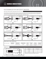
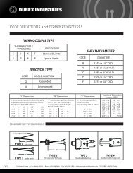
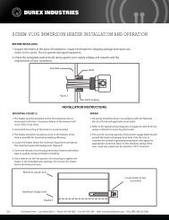
External Dimensions<br />
The mounting brackets can be attached<br />
on the sides of the controller.<br />
However, to make the controller<br />
waterproof and dustproof, attach the<br />
mounting brackets to the top and bottom.<br />
(4 places).<br />
96<br />
<strong>RB</strong>900<br />
(Optional)<br />
Up to 4 points<br />
(<strong>RB</strong>100 : Up to 3 points, Heat/Cool type : Up to 2 points)<br />
See page 7 "Maximum number of digital outputs (DO)<br />
by combinations of output (OUT1 and OUT2)<br />
Process high, Process low, Deviation high, Deviation low,<br />
Deviation high/low<br />
a) Hold/Re-hold action<br />
• Hold action is activated at power-on and stop-to-run.<br />
Re-hold action is activated at power-on, stop-to-run,<br />
and the control set value change.<br />
b) Alarm output ON/OFF at stop mode is selectable.<br />
c) Energized/de-energized action is configurable.<br />
d) Differential gap : 0 (0.0) to span<br />
d) Delay timer : 0 to 600 sec<br />
*1 , Band, Set value high, Set value low,<br />
LBA (Control loop break alarm), Heater break alarm (HBA),<br />
Output of the communication monitoring result,<br />
RUN status monitor<br />
*1: Two types of alarm settings are field-selectable.<br />
1. Independent high and low settings.<br />
2. Common high/low setting<br />
(Factory setting, unless specified in alarm code<br />
when ordering)<br />
1.0 *1<br />
7.9 60<br />
70.1<br />
• If you specified the waterproof and dustproof structure,<br />
four mounting brackets are included with the <strong>RB</strong>900<br />
as accessories.<br />
106.1<br />
91.8<br />
*1 : Case rubber packing (optional) [Waterproof/dustproof]<br />
91.8<br />
106.1<br />
Terminal<br />
cover<br />
(Optional)<br />
72<br />
<strong>RB</strong>700<br />
48<br />
7.9<br />
Waterproof/Dustproof<br />
(Optional)<br />
NEMA4X, IP66<br />
• Waterproof/Dustproof protection only effective from the front in panel<br />
mounted installation.<br />
General <strong>Specification</strong>s<br />
Supply voltage<br />
Power consumption<br />
Rush current<br />
Power failure<br />
Memory backup<br />
Ambient temperature<br />
Ambient humidity<br />
External dimensions<br />
(W x H x D)<br />
Weight<br />
Compliance with<br />
standards<br />
*1<br />
1.0<br />
60<br />
81.7<br />
68.5 67.8<br />
a) 90 to 264V AC (50/60Hz, Selectable)<br />
Rating : 100 to 240V AC<br />
b) 24V AC ±10% (50/60Hz, Selectable)<br />
Rating : 24V AC<br />
c) 24V DC ±10%<br />
Rating : 24V DC<br />
a) 100 to 240V AC type<br />
<strong>RB</strong>900 : 9.0VA (240V), <strong>RB</strong>700 : 8.7VA (240V)<br />
<strong>RB</strong>500 : 8.7VA (240V), <strong>RB</strong>400 : 8.7VA (240V)<br />
<strong>RB</strong>100 : 8.5VA (240V)<br />
b) 24V AC type<br />
<strong>RB</strong>900 : 6.0VA, <strong>RB</strong>700 : 5.8VA<br />
<strong>RB</strong>500 : 5.8VA, <strong>RB</strong>400 : 5.8VA<br />
<strong>RB</strong>100 : 4.7VA<br />
c) 24V DC type<br />
<strong>RB</strong>900 : 147mA, <strong>RB</strong>700 : 141mA<br />
<strong>RB</strong>500 : 141mA, <strong>RB</strong>400 : 141mA<br />
<strong>RB</strong>100 : 108mA<br />
a) 100 to 240V AC type<br />
Less than 13.3A (240V), Less than 5.6A (100V)<br />
b) 24V AC type<br />
Less than 16.3A<br />
c) 24V DC type<br />
Less than 11.5A<br />
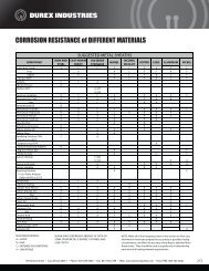
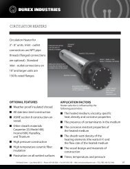
The mounting brackets can be fixed on<br />
both sides (<strong>RB</strong>400), top and bottom (<strong>RB</strong>500),<br />
but to obtain water- and dust-proof protection,<br />
install brackets (two each) only on top and<br />
bottom (<strong>RB</strong>400) and on both sides (<strong>RB</strong>500).<br />
<strong>RB</strong>500 <strong>RB</strong>400<br />
A power failure of 20msec or less will not affect the<br />
control action.<br />
• <strong>RB</strong>100, 24V AC/DC type : 10msec or less<br />
Backed up by Nonvolatile memory<br />
• Data retaining period : Approx. 10 years<br />
• Number of writing : Approx. 1,000,000 times.<br />
(Depending on storage and operating conditions.)<br />
0 to 50°C (32 to 122°F)<br />
10 to 90%RH (Non condensing)<br />
• Absolute humidity : MAX.W.C29.3g/m3 dry air at 101.3kPa<br />
<strong>RB</strong>900: 96 x 96 x 60mm<br />
<strong>RB</strong>700: 72 x 72 x 60mm<br />
<strong>RB</strong>500: 96 x 48 x 60mm<br />
<strong>RB</strong>400: 48 x 96 x 60mm<br />
<strong>RB</strong>100: 48 x 48 x 63mm<br />
<strong>RB</strong>900: Approx.250g, <strong>RB</strong>700: Approx. 200g<br />
<strong>RB</strong>500: Approx.190g, <strong>RB</strong>400: Approx. 185g,<br />
<strong>RB</strong>100: Approx.120g<br />
UL,cUL,CE,C-Tick<br />
96<br />
Terminal<br />
cover<br />
(Optional)<br />
82.2<br />
<strong>RB</strong>100<br />
48<br />
1<br />
60<br />
70.1<br />
91.8<br />
44.8<br />
106.1 59.1<br />
44 8<br />
1.0*1<br />
7.9 63<br />
79.1<br />
Terminal cover<br />
(Optional)<br />
Terminal<br />
cover<br />
(Optional)<br />
44.8<br />
48.2<br />
59.3<br />
5
6<br />
6<br />
Model and Suffix Codes<br />
Model and Suffix Codes<br />
48 x 48mm (1/16 DIN size) <strong>RB</strong>100<br />
48 x 96mm (1/8 DIN Vertical size) <strong>RB</strong>400<br />
<strong>Specification</strong>s<br />
48 96 x 48mm (1/16 (1/8 DIN Horizontal size) size) <strong>RB</strong>100 <strong>RB</strong>500<br />
48 72 x x 96mm 72mm (1/8 (3/16 DIN Vertical size) size) <strong>RB</strong>700 <strong>RB</strong>400<br />
<strong>Specification</strong>s<br />
96 x 48mm 96mm (1/8 (1/4 DIN Horizontal size) size) <strong>RB</strong>900 <strong>RB</strong>500<br />
PID<br />
72 x<br />
control<br />
72mm<br />
with<br />
(3/16<br />
AT<br />
DIN<br />
(Reverse<br />
size)<br />
action) <strong>RB</strong>700<br />
F<br />
96 x 96mm (1/4 DIN size)<br />
<strong>RB</strong>900<br />
PID control with AT (Direct action)<br />
D<br />
PID control with AT (Reverse action)<br />
F<br />
Control Method<br />
Heat/Cool PID control with AT<br />
G<br />
PID control with AT (Direct action)<br />
D<br />
Heat/Cool PID control with AT for extruder (Air cooling type) A<br />
Control Method<br />
Heat/Cool PID control with AT<br />
G<br />
Heat/Cool PID control with AT for extruder (Water cooling type) W<br />
Heat/Cool PID control with AT for extruder (Air cooling type) A<br />
Input and range See Input range Code Table<br />
Heat/Cool PID control with AT for extruder (Water cooling type) W<br />
Output 1 (OUT1) Control output See Output 1 Code Table<br />
Input and range See Input range Code Table<br />
Output 2 (OUT2)<br />
*1,*2 Not supplied<br />
N<br />
Output 1 (OUT1) Control output See Output 1 Code Table<br />
(Control output or analog retransmission output (AO) See Output 2 Code Table<br />
Output 2 (OUT2)<br />
*1,*2 Not supplied<br />
N<br />
(Control output or analog retransmission output (AO) 24V<br />
See<br />
AC/DC<br />
3<br />
Power Supply<br />
Output 2 Code Table<br />
100 to 240V AC<br />
4<br />
24V AC/DC<br />
3<br />
Power Supply<br />
*3 Not supplied<br />
N<br />
100 to 240V AC<br />
4<br />
DO 1 points (DO1)<br />
1<br />
Digital output (DO)<br />
*3 Not supplied<br />
N<br />
DO 2 points (DO1, DO2)<br />
2<br />
DO 1 points (DO1)<br />
1<br />
Digital output (DO)<br />
DO 4 points (DO1 to DO4)<br />
• Available for <strong>RB</strong>400/500/700/900 only 4<br />
DO 2 points (DO1, DO2)<br />
2<br />
Not supplied<br />
DO 4 points (DO1 to DO4)<br />
• Available for <strong>RB</strong>400/500/700/900 only 4<br />
For CTL-6-P-N (0 to 30A) 1 point<br />
• When digital output code is "N", cannot be specified.<br />
CT input<br />
Not supplied<br />
For CTL-12-S56-10L-N (0 to 100A) 1 point • When digital output code is "N", cannot be specified.<br />
For CTL-6-P-N (0 to 30A) 1 point<br />
• When digital output code is "N", cannot be specified.<br />
CT input<br />
For CTL-6-P-N (0 to 30A) 2 point<br />
• When digital output code is "N", cannot be specified.<br />
For CTL-12-S56-10L-N (0 to 100A) 1 point • When digital output code is "N", cannot be specified.<br />
For CTL-12-S56-10L-N (0 to 100A) 2 point • When digital output code is "N", cannot be specified.<br />
For CTL-6-P-N (0 to 30A) 2 point<br />
• When digital output code is "N", cannot be specified.<br />
Not supplied<br />
For CTL-12-S56-10L-N (0 to 100A) 2 point • When digital output code is "N", cannot be specified.<br />
RS-485 (ANSI/RKC standard protocol)<br />
Not supplied<br />
RS-485 (MODBUS protocol)<br />
Communication/Digital input (DI) RS-485 (ANSI/RKC standard protocol)<br />
DI 2 points<br />
RS-485 (MODBUS protocol)<br />
Communication/Digital input (DI) RS-485 (ANSI/RKC standard protocol) + DI 2 points • Available for <strong>RB</strong>400/500/700/900 only<br />
DI 2 points<br />
RS-485 (MODBUS protocol) + DI 2 points<br />
• Available for <strong>RB</strong>400/500/700/900 only<br />
RS-485 (ANSI/RKC standard protocol) + DI 2 points • Available for <strong>RB</strong>400/500/700/900 only<br />
Not supplied<br />
Waterproof/Dustproof RS-485 (MODBUS protocol) + DI 2 points<br />
• Available for <strong>RB</strong>400/500/700/900 only<br />
Not<br />
Waterproof/Dustproof<br />
supplied<br />
protection<br />
Waterproof/Dustproof<br />
Case color<br />
White case<br />
Waterproof/Dustproof protection<br />
Case color<br />
White<br />
Black case<br />
case<br />
Quick start code<br />
No quick start code (Default setting)<br />
Black case<br />
Quick start code<br />
No<br />
Specify<br />
quick<br />
quick<br />
start<br />
start<br />
code<br />
code<br />
(Default<br />
(DO<br />
setting)<br />
type)<br />
Instrument version Version Specify quick symbol start code (DO type)<br />
N<br />
P<br />
N<br />
S<br />
P<br />
T<br />
S<br />
U<br />
T<br />
U<br />
N<br />
5<br />
N<br />
6<br />
5<br />
A<br />
6<br />
B<br />
A<br />
C<br />
B<br />
C<br />
N<br />
1<br />
N<br />
1<br />
N<br />
A<br />
N<br />
A<br />
N<br />
1<br />
N<br />
1<br />
/ Y<br />
/ Y<br />
Y<br />
*1 When Instrument control method versionis selected for PID Version control symbol (Code : F, D), output 2 is available for analog retransmission output.<br />
*2 On the <strong>RB</strong>100, the event 3 output function can be specified for output 2.<br />
*1<br />
*3 The<br />
When<br />
number<br />
control<br />
of<br />
method<br />
DO points<br />
is selected<br />
is limited<br />
for<br />
in<br />
PID<br />
some<br />
control<br />
combinations<br />
(Code : F,<br />
of<br />
D),<br />
OUT1<br />
output<br />
and<br />
2 is<br />
OUT2<br />
available<br />
(control<br />
for<br />
output)<br />
analog retransmission<br />
types.<br />
output.<br />
*2 On the <strong>RB</strong>100, the event 3 output function can be specified for output 2.<br />
*3 Input The number Range of DO points Code is limited Table in some combinations of OUT1 and OUT2 (control output) types.<br />
Y<br />
Temperature Input Group (Field-programmable)<br />
Input Range Code Table<br />
Thermocouple<br />
Temperature Input Group (Field-programmable)<br />
RTD<br />
Input Code Range<br />
Input Code Range<br />
Input<br />
Thermocouple<br />
1 K 01 0 to 200°C S 2 S 02 0 to 1769°C RTD<br />
Input KCode 02 0Range to 400°C (JIS/IEC) Input SCode A2 0Range to 3216°F Input<br />
1 K 01 03 0 to to 200°C 600°C S 2 SB 02 01 4000 to 1800°C 1769°C<br />
K 02 04 0 to to 400°C 800°C (JIS/IEC) B SB A2 02 0 to 1820°C 3216°F<br />
K 03 05 0 to to 1000°C 600°C<br />
(JIS/IEC) 2 BB A1 01 400 800 to 1800°C 3200°F<br />
K K 04 06 0 to to 1200°C 800°C B BB A2 02 0 to 1820°C 3308°F<br />
(JIS/IEC) K 05 41 -200 0 to +1372°C 1000°C<br />
(JIS/IEC) 1 BE A1 01 8000 to 3200°F 800°C<br />
K K 06 09 0.00 to to 400.0°C 1200°C E BE A2 02 0 to 1000°C 3308°F<br />
(JIS/IEC) K 41 10 -200 0.0 to<br />
+1372°C 800.0°C<br />
(JIS/IEC) 1 EE A1 01 00 to 1600°F 800°C Pt100<br />
K 09 43 -199.9 0.0 to to +400.0°C 400.0°C E EE A2 02 00 to 1000°C 1832°F (JIS/IEC)<br />
K A1 10 0.00 to to 800.0°C 800°F<br />
(JIS/IEC) NE A1 01 00 to 1200°C 1600°F Pt100<br />
K A2 43 -199.9 0 to to +400.0°C 1600°F N NE A2 02 00 to 1300°C 1832°F (JIS/IEC)<br />
K C7 A1 -328 0 to to +2501°F 800°F (JIS/IEC) N A1 01 00 to 1200°C 2300°F<br />
K C8 A2 -100.0 0 to to +752.0°F 1600°F N N A2 02 00 to 1300°C 2372°F<br />
1 KJ C7 01 -328 0 to to +2501°F 200°C (JIS/IEC)<br />
1 NT A1 02 -199.9 0 to +100.0°C 2300°F<br />
KJ C8 02 -100.0 0 to to +752.0°F 400°C<br />
NT A2 03 -100.0 0 to +200.0°C 2372°F<br />
1 J 01 03 0 to to 200°C 600°C T 1 TT 02 05 -199.9 -199.9 to +100.0°C +300.0°C<br />
J 02 04 0 to to 400°C 800°C<br />
(JIS/IEC)<br />
TT 03 06 -100.0 0.0 to +200.0°C 400.0°C<br />
J 03 05 0 to to 1000°C 600°C<br />
J<br />
T TT C7 05 -199.9 0.0 to +300.0°C 600.0°F<br />
J 04 06 0 to 1200°C 800°C<br />
(JIS/IEC)<br />
TT C8 06 -199.9 0.0 to +300.0°F 400.0°C<br />
(JIS/IEC)<br />
J 05 0 to 1000°C<br />
J J 15 -200 to +1200°C<br />
T C7 C9 -328 0.0 to 600.0°F +752°F<br />
JJ 06 07 -199.9 0 to to +300.0°C 1200°C<br />
T C8 -199.9 to +300.0°F<br />
(JIS/IEC)<br />
2 W 01 0 to 2000°C<br />
J A1 15 -200 0 to to +1200°C 800°F W5Re/W26Re WT C9 02 -328 0 to 2320°C +752°F<br />
J A2 07 -199.9 0 to +300.0°C 1600°F (ASTM) 2 W A4 01 0 to 2000°C 4208°F JPt100<br />
J A1 B9 -328 0 to +2192°F 800°F W5Re/W26Re WA 02 01 0 to 2320°C 1300°C (JIS)<br />
J C8 A2 -199.9 0 to +550.0°F 1600°F (ASTM)<br />
PLII WA A4 02 0 to 1390°C 4208°F JPt100<br />
R 2 RJ B9 02 -328 0 to +2192°F 1769°C<br />
(NBS)<br />
A A1 01 0 to 1300°C 2400°F (JIS)<br />
(JIS/IEC) RJ C8 A2 -199.9 0 to +550.0°F 3216°F PLII A A2 02 0 to 1390°C 2534°F<br />
R 2<br />
*1 : Accuracy is<br />
R<br />
not<br />
02<br />
guaranteed<br />
0 to<br />
for<br />
1769°C<br />
less than -100°C (NBS) (-146°F) A. A1 0 to 2400°F<br />
*2 (JIS/IEC) : Accuracy is R not A2guaranteed<br />
0 tofor<br />
less 3216°F than 400°C (752°F) Afor Input A2 Type 0R, toS,<br />
B, 2534°F and W5Re/W26Re.<br />
*1 : Accuracy is not guaranteed for less than -100°C (-146°F) .<br />
*2 : Accuracy Output is not 1 guaranteed Code Table for less than 400°C Output (752°F) for 2 Input Code Type R, Table S, B, and W5Re/W26Re.<br />
Code<br />
D 01<br />
DCode 02<br />
D 01 03<br />
D 02 04<br />
D 03 05<br />
D 04 06<br />
D 05 07<br />
D 06 08<br />
D 07 09<br />
D 08 10<br />
D A2 09<br />
D A3 10<br />
D A2 A4<br />
D A3 A5<br />
D A4 A6<br />
D A5 A7<br />
D A6 A8<br />
D A7 A9<br />
D A8 B2<br />
DP A9 01<br />
DP B2 02<br />
P 01 03<br />
P 02 04<br />
P 03 05<br />
P 04 06<br />
P 05 07<br />
P 06 08<br />
P 07 09<br />
P 08 10<br />
P 09<br />
P 10<br />
DC Current • Voltage Group<br />
(Field-programmable)<br />
DC Current • Voltage Group<br />
Range<br />
Input Code Range<br />
-199.9 to +649.0°C (Field-programmable)<br />
0 to 1V DC 3 01<br />
-199.9 Range to +200.0°C 0 to Input 5V DC 4Code 01 -1999 Range to +9999<br />
-199.9 -100.0 to +649.0°C +50.0°C 0 to 10V 1V DC 35 01 01 (Programmable)<br />
-199.9 -100.0 to +200.0°C +100.0°C 1 0 to 5V DC<br />
46 01 -1999 to +9999<br />
-100.0 -100.0 to +200.0°C +50.0°C 0 to 10V 20mA DC DC 57 01 (Programmable)<br />
Factory set value<br />
: 0.0 to 100.0<br />
-100.0 0.0 to +100.0°C 50.0°C 1 4 to 5V 20mA DC DC 68 01<br />
-100.0 0.0 to +200.0°C 100.0°C 0 to 20mA DC 7 01 Factory set value<br />
• For current input, connect : 0.0 to is 100.0 a 250Ω<br />
0.0 to 200.0°C 50.0°C 4 to 20mA DC<br />
shunt resistor<br />
8<br />
to the<br />
01<br />
input terminals.<br />
0.0 to 100.0°C 300.0°C • Model For current code input, : KD100-55 connect is a 250Ω<br />
0.0 to 200.0°C 500.0°C shunt resistor to the input terminals.<br />
-199.9 0.0 to +400.0°F 300.0°C Model code : KD100-55<br />
-199.9 0.0 to +200.0°F 500.0°C<br />
-199.9 -199.9 to +400.0°F +100.0°F<br />
-199.9 -199.9 to +200.0°F +300.0°F<br />
-199.9 0.0 to +100.0°F 100.0°F<br />
-199.9 0.0 to +300.0°F 200.0°F<br />
0.0 to 100.0°F 400.0°F<br />
0.0 to 200.0°F 500.0°F<br />
-199.9 0.0 to<br />
+900.0°F 400.0°F<br />
-199.9 0.0 to to +649.0°C 500.0°F<br />
-199.9 to +200.0°C +900.0°F<br />
-199.9 -100.0 to to +649.0°C +50.0°C<br />
-199.9 -100.0 to +100.0°C +200.0°C<br />
-100.0 to +200.0°C +50.0°C<br />
-100.0 0.0 to +100.0°C 50.0°C<br />
-100.0 0.0 to +200.0°C 100.0°C<br />
0.0 to 200.0°C 50.0°C<br />
0.0 to 100.0°C 300.0°C<br />
0.0 to 200.0°C 500.0°C<br />
0.0 to 300.0°C<br />
0.0 to 500.0°C<br />
Output Type Code<br />
Output Type<br />
Code<br />
Output Type<br />
Code Remarks<br />
Relay Output contact output 1 Code MTable<br />
Relay Output contact output 2 Code (Cool side Table output) M Relay contact output *1 (Event 3 [DO3] output) P Only <strong>RB</strong>100<br />
Voltage Output pulse Type output Code V<br />
Voltage pulse Output output Type (Cool side output) Code V 0 to 20mA DC (Analog Output retransmission Type output [AO]) Code R Only Remarks PID control<br />
Relay 0 to 5V contact DC output M4<br />
Relay 0 to 5V contact DC output (Cool side output) M4<br />
Relay 4 to 20mA contact DCoutput<br />
(Analog *1 retransmission (Event 3 [DO3] output output) [AO]) SP<br />
Only <strong>RB</strong>100 PID control<br />
0 Voltage to 10V pulse DC output V5<br />
Voltage 0 to 10V pulse DC output (Cool side output) V5<br />
0 to 20mA 5V DC DC (Analog retransmission output [AO]) RX<br />
Only PID control<br />
0 1 to 5V DC<br />
64<br />
0 1 to 5V DC (Cool side output) 46<br />
4 0 to 20mA 10V DC DC (Analog retransmission output [AO]) SY<br />
Only PID control<br />
0 to 10V 20mA DC DC<br />
57<br />
0 to 20mA 10V DC DC (Cool side output) 75<br />
0 1 to to 5V DC (Analog (Analog retransmission output [AO]) XZ<br />
Only PID PID control<br />
1 4 to 5V 20mA DC DC<br />
68<br />
1 4 to 5V 20mA DC DC (Cool side output) 86<br />
*1 0 to : Selectable 10V DC only (Analog when retransmission DO 2 points(DO1,DO2) output [AO]) is supplied Y Only to <strong>RB</strong>100 PID control with PID action.<br />
0 Triac to 20mA output DC<br />
T7<br />
0 Triac to 20mA output DC (Cool (Cool side side output) T7<br />
1 to 5V DC (Analog retransmission output [AO]) Z Only PID control<br />
Open 4 to 20mA collector DC output D8<br />
4 Open to 20mA collector DC output (Cool side side output) D8<br />
*1 : Selectable only when DO 2 points(DO1,DO2) is supplied to <strong>RB</strong>100 with PID action.<br />
Triac output<br />
T<br />
Triac output (Cool side output) T<br />
Open Maximum collector output number D of digital Open outputs collector (DO) output (Cool by combinations side output) D of output (OUT1 and OUT2)<br />
OUT2 (Including transmission output)<br />
Maximum number of digital outputs (DO) by combinations of output (OUT1 and ( OUT2) : Represents selection of digital outputs<br />
No OUT2 M, T, D V<br />
V Current Voltage<br />
output<br />
OUT2 (Including (10 mA) transmission (20 mA)<br />
-DO3 and DO4 are not available.)<br />
output) output output<br />
M, T, D<br />
( : Represents selection of digital outputs<br />
*1<br />
No OUT2 4<br />
4<br />
4<br />
M, T, D V<br />
V4<br />
Current 4 Voltage 4 *1 When<br />
V (Load: 10 mA) output 4<br />
4 (10 4mA)<br />
(20 4mA)<br />
-DO3<br />
the instrument<br />
and DO4 are<br />
has<br />
not<br />
two<br />
available.)<br />
digital outputs<br />
output 2 output 2<br />
(DO1 and DO2) and no OUT2 output, "V" type<br />
OUT1 *1 M, V (Load: T, D 20 mA)<br />
4<br />
4<br />
4<br />
42<br />
24<br />
42<br />
*1 When output the (load: instrument 40mA) can has be two specified digital outputs for OUT1.<br />
V Current (Load: output 10 mA)<br />
4<br />
4 42<br />
42<br />
2<br />
2<br />
(DO1 and DO2) and no OUT2 output, "V" type<br />
OUT1 V Voltage (Load: output 20 mA)<br />
4<br />
4 42<br />
2 2<br />
2<br />
output (load: 40mA) can be specified for OUT1.<br />
Current output<br />
4<br />
4 2 2 2<br />
2<br />
Voltage output<br />
4<br />
4 2 2 2<br />
2
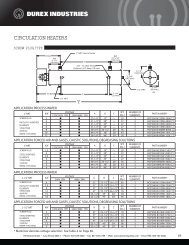
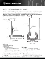
Rear Terminals<br />
• Use a solderless terminal for screw size M3, width 5.8mm or less. No Contents No Contents<br />
<strong>RB</strong>900<br />
R<br />
1<br />
<strong>RB</strong>400<br />
1 L<br />
L<br />
13 SG<br />
(Optional)<br />
100 to 240V 24V AC 24V DC Power supply<br />
2 N<br />
N<br />
14 T/R(A)<br />
Communication<br />
RS-485<br />
3<br />
Control output 1, 2<br />
(OUT2)<br />
15 T/R(B)<br />
NO Triac<br />
(OUT1,2) or<br />
or<br />
(2)<br />
4<br />
(AO) Analog retransmission 16<br />
(Optional)<br />
(DI 2)<br />
(1) (2) (3) (4)<br />
output (AO)<br />
Digital input<br />
5<br />
(1) Relay contact output<br />
(1)<br />
17 (DI 1)<br />
NO Triac (OUT1) (2) Voltage pulse / Current/Voltage<br />
(DI 1, 2)<br />
(3) SSR (Triac)<br />
COM<br />
6 (1) (2) (3) (4)<br />
(4) Open collector<br />
18<br />
7 (DO2)<br />
(Optional)<br />
19 (DO4)<br />
(Optional)<br />
NO<br />
NO<br />
Digital output 1, 2<br />
Digital output 3, 4<br />
8 (DO1)<br />
NO<br />
20 (DO3)<br />
(DO1,2)<br />
NO<br />
(DO3,4)<br />
9 COM<br />
Relay contact output 21 COM<br />
Relay contact output<br />
10 A<br />
Measuring input 22<br />
(Optional)<br />
11 B<br />
(1) Thermocouple<br />
CT2 23<br />
CT1,CT2 input<br />
(2) RTD<br />
CT1<br />
12 B<br />
(3) Voltage/Current<br />
(1) (2) (3)<br />
24<br />
No Contents No Contents<br />
No Contents<br />
1 L<br />
L<br />
19<br />
10 (DO2)<br />
(Optional)<br />
100 to 240V<br />
Power supply<br />
NO<br />
AC24V DC24V<br />
2 N<br />
N<br />
20<br />
11 (DO1) Digital output 1, 2<br />
NO<br />
(DO1,2)<br />
3<br />
Control output 1, 2 21<br />
COM<br />
12<br />
Relay contact output<br />
NO Triac<br />
(OUT1,2) or<br />
Analog retransmission<br />
(2)<br />
4<br />
22<br />
(Optional)<br />
(DI 2)<br />
13<br />
(Optional)<br />
(1) (2) (3) (4)<br />
output (AO)<br />
(1) Digital input<br />
CT2<br />
5<br />
(1) Relay contact output 23<br />
14<br />
(DI 1)<br />
NO Triac<br />
(2) Voltage pulse / Current/Voltage<br />
(DI 1, 2)<br />
CT1<br />
CT1,CT2 input<br />
(3) SSR (Triac)<br />
COM<br />
6<br />
24<br />
15<br />
(1) (2) (3) (4)<br />
(4) Open collector<br />
COM<br />
7<br />
(Optional)<br />
(DO4)<br />
25 SG<br />
(Optional) 16 A Measuring input<br />
NO<br />
Digital output 3, 4<br />
8 (DO3)<br />
NO<br />
26 T/R(A) Communication<br />
B 17<br />
(1) Thermocouple<br />
(DO3,4)<br />
(2) RTD<br />
RS-485<br />
COM 9<br />
Relay contact output 27 T/R(B)<br />
B 18<br />
(3) Voltage/Current<br />
(1) (2) (3)<br />
No Contents<br />
No Contents No Contents<br />
1 L<br />
L<br />
SG<br />
(2)<br />
13 (Optional) (Optional)<br />
(DI 2)<br />
7<br />
(DO2)<br />
(Optional)<br />
100 to 240V 24V AC 24V DC Power supply<br />
NO<br />
Communication<br />
2 N<br />
N<br />
T/R(A)<br />
(1)<br />
14<br />
Digital input<br />
Digital output 1, 2<br />
8<br />
(DO1)<br />
RS-485<br />
(DI 1)<br />
NO<br />
(DI 1, 2)<br />
(DO1,2)<br />
3<br />
Control output 1, 2<br />
15 T/R(B)<br />
COM<br />
9 COM<br />
(OUT2)<br />
Relay contact output<br />
NO Triac<br />
(OUT1,2) or<br />
or<br />
4<br />
(AO) Analog retransmission 16<br />
(Optional) 10 A<br />
(1) (2) (3) (4) output, Digital output (AO)<br />
Measuring input<br />
5<br />
CT2<br />
B<br />
(1) Relay contact output 17<br />
11<br />
(1) Thermocouple<br />
NO Triac (OUT1)<br />
CT1,CT2 input<br />
(2) Voltage pulse / Current/Voltage CT1<br />
(2) RTD<br />
B<br />
6<br />
(3) SSR (Triac)<br />
(1) (2) (3) (4)<br />
18<br />
12 (1) (2) (3) (3) Voltage/Current<br />
(4) Open collector<br />
Panel Cutout Dimensions<br />
< Close horizontal mounting > • Up to 6 units<br />
Unit : mm<br />
<strong>RB</strong>900 +0.8 <strong>RB</strong>400 +0.6 <strong>RB</strong>500<br />
L 0<br />
L 0<br />
92 +0.8<br />
R<br />
7 (DO2)<br />
NO<br />
8 (DO1)<br />
NO<br />
9 COM<br />
10 A<br />
(Optional)<br />
Digital output 1, 2<br />
(DO1,2)<br />
Relay contact output<br />
Measuring input<br />
19<br />
20<br />
21<br />
22<br />
NO<br />
NO<br />
COM<br />
(DO4)<br />
(DO3)<br />
(Optional)<br />
Digital output 3, 4<br />
(DO3,4)<br />
Relay contact output<br />
(Optional)<br />
1<br />
11 B<br />
(1) Thermocouple<br />
CT2 23<br />
CT1,CT2 input<br />
(2) RTD<br />
CT1<br />
12 B<br />
(3) Voltage/Current<br />
(1) (2) (3)<br />
24<br />
No Contents No Contents<br />
No Contents<br />
1 L<br />
L<br />
19<br />
10 (DO2)<br />
(Optional)<br />
100 to 240V<br />
Power supply<br />
NO<br />
AC24V DC24V<br />
2 N<br />
N<br />
20<br />
11 (DO1) Digital output 1, 2<br />
NO<br />
(DO1,2)<br />
3<br />
Control output 1, 2 21<br />
COM<br />
12<br />
Relay contact output<br />
NO Triac<br />
(OUT1,2) or<br />
Analog retransmission<br />
(2)<br />
4<br />
22<br />
(Optional)<br />
(DI 2)<br />
13<br />
(Optional)<br />
(1) (2) (3) (4)<br />
output (AO)<br />
(1) Digital input<br />
CT2<br />
5<br />
(1) Relay contact output 23<br />
14<br />
(DI 1)<br />
NO Triac<br />
(2) Voltage pulse / Current/Voltage<br />
(DI 1, 2)<br />
CT1<br />
CT1,CT2 input<br />
(3) SSR (Triac)<br />
COM<br />
6<br />
24<br />
15<br />
(1) (2) (3) (4)<br />
(4) Open collector<br />
COM<br />
7<br />
(Optional)<br />
(DO4)<br />
25 SG<br />
(Optional) 16 A Measuring input<br />
NO<br />
Digital output 3, 4<br />
8 (DO3)<br />
NO<br />
26 T/R(A) Communication<br />
B 17<br />
(1) Thermocouple<br />
(DO3,4)<br />
(2) RTD<br />
RS-485<br />
COM 9<br />
Relay contact output 27 T/R(B)<br />
B 18<br />
(3) Voltage/Current<br />
(1) (2) (3)<br />
No Contents<br />
No Contents No Contents<br />
1 L<br />
L<br />
SG<br />
(2)<br />
13 (Optional) (Optional)<br />
(DI 2)<br />
7<br />
(DO2)<br />
(Optional)<br />
100 to 240V 24V AC 24V DC Power supply<br />
NO<br />
Communication<br />
2 N<br />
N<br />
T/R(A)<br />
(1)<br />
14<br />
Digital input<br />
Digital output 1, 2<br />
8<br />
(DO1)<br />
RS-485<br />
(DI 1)<br />
NO<br />
(DI 1, 2)<br />
(DO1,2)<br />
(OUT2)<br />
3<br />
Control output 1, 2<br />
or<br />
15 T/R(B)<br />
COM<br />
9 COM<br />
(OUT2)<br />
Relay contact output<br />
NO Triac<br />
(OUT1,2) or<br />
or<br />
(AO)<br />
4<br />
(AO) Analog retransmission 16<br />
(Optional) 10 A<br />
(1) (2) (3) (4) output, Digital output (AO)<br />
Measuring input<br />
5<br />
(OUT1)<br />
CT2<br />
B<br />
(1) Relay contact output 17<br />
11<br />
(1) Thermocouple<br />
NO Triac (OUT1)<br />
CT1,CT2 input<br />
(2) Voltage pulse / Current/Voltage CT1<br />
(2) RTD<br />
B<br />
6<br />
(3) SSR (Triac)<br />
(1) (2) (3) (4)<br />
18<br />
12 (1) (2) (3) (3) Voltage/Current<br />
(4) Open collector<br />
Panel Cutout Dimensions<br />
< Close horizontal mounting > • Up to 6 units<br />
Unit : mm<br />
L=48 x n-3<br />
L=96 x n-4 L=48 x n-3<br />
n : Number of controllers<br />
92 25<br />
n : Number of controllers (2=