INTEGRA Ci3 - Crompton Instruments
INTEGRA Ci3 - Crompton Instruments
INTEGRA Ci3 - Crompton Instruments

You also want an ePaper? Increase the reach of your titles
YUMPU automatically turns print PDFs into web optimized ePapers that Google loves.
Introduction<br />
<strong>INTEGRA</strong> <strong>Ci3</strong><br />
Digital Energy Meter for Single- and<br />
Three-Phase Electrical Systems<br />
Model Type: CI3-01 / CI3-VT<br />
Installation and Operating<br />
Instructions<br />
Tyco Electronics UK Ltd.<br />
Freebournes Road,<br />
Witham,<br />
Essex,<br />
CM8 3AH,<br />
England.<br />
Phone: +44 (0)870 870 7500<br />
Fax: +44 (0)870 240 5287<br />
Email: crompton.info@tycoelectronics.com<br />
www.crompton-instruments.com<br />
http://energy.tycoelectronics.com<br />
The Integra <strong>Ci3</strong> digital meter is designed for accurate<br />
measurement and display of all major electrical and power<br />
quality parameters, in single-phase two wire, and three-phase<br />
three and four-wire system configurations.<br />
This manual provides all the necessary instructions to safely<br />
install and operate the instrument. However, for additional<br />
operating parameters please refer to the full manual on<br />
www.crompton-instruments.com.<br />
Measurement<br />
In measurement mode, the buttons control the displayed<br />
measurement as follows:<br />
is used to select the Voltage and Frequency display<br />
screens.<br />
In set-up mode this is the “Back” button.<br />
is used to select the Current display screens.<br />
In set-up mode this is the “Up” button.<br />
is used to select the Power and Power Factor display<br />
screens.<br />
In set-up mode this is the “Down” button.<br />
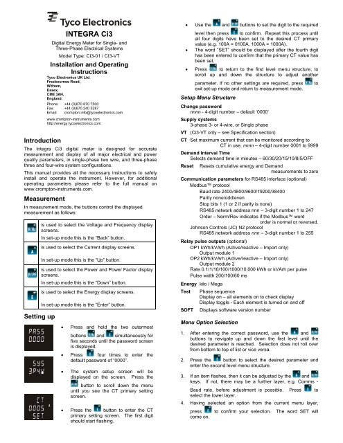
Setting up<br />
is used to select the Energy display screens.<br />
In set-up mode this is the “Enter” button.<br />
Press and hold the two outermost<br />
buttons and simultaneously for<br />
five seconds until the password screen<br />
is displayed.<br />
Press four times to enter the<br />
default password of “0000”.<br />
<br />
The system setup screen will be<br />
displayed on the screen. Press the<br />
button to scroll down the menu<br />
until you see the CT primary setting<br />
screen.<br />
Press the button to enter the CT<br />
primary setting screen. The first digit<br />
should start flashing.<br />
Use the and buttons to set the digit to the required<br />
level then press to confirm. Repeat this process until<br />
all four digits have been set to the desired CT primary<br />
value (e.g. 100A = 0100A, 1000A = 1000A).<br />
The word “SET” should be displayed after the fourth digit<br />
has been entered to confirm that the primary CT value has<br />
been set.<br />
Press to return to the first level menu structure, to<br />
scroll up and down the structure to adjust another<br />
parameter. If no other settings are required, press to<br />
exit set-up mode and return to measurement mode.<br />
Setup Menu Structure<br />
Change password<br />
nnnn - 4-digit number – default ‘0000’<br />
Supply systems<br />
3-phase 3- or 4-wire, or Single phase<br />
VT (<strong>Ci3</strong>-VT only – see Specification section)<br />
CT Set maximum current that can be monitored according to<br />
CT in use, nnnn – 4-digit number 0001 to 9999<br />
Demand Interval Time<br />
Selects demand time in minutes – 60/30/20/15/10/8/5/OFF<br />
Reset Resets cumulative energy and Demand<br />
measurements to zero<br />
Communication parameters for RS485 interface (optional)<br />
Modbus protocol<br />
Baud rate 2400/4800/9600/19200/38400<br />
Parity none/odd/even<br />
Stop bits 1 (1 or 2 if parity is none)<br />
RS485 network address nnn – 3-digit number 1 to 247<br />
Order – Norm/Rev indicates if the Modbus word<br />
order is normal or reversed.<br />
Johnson Controls (JC) N2 protocol<br />
RS485 network address nnn – 3-digit number 1 to 255<br />
Relay pulse outputs (optional)<br />
OP1 kWh/kVArh (Active/reactive – Import only)<br />
Output module 1<br />
OP2 kWh/kVArh (Active/reactive – Import only)<br />
Output module 2<br />
Rate 0.1/1/10/100/1000/10,000 kWh or kVArh per pulse<br />
Pulse width 200/100/60 ms<br />
Energy kilo / Mega<br />
Test<br />
SOFT<br />
Phase sequence<br />
Display on – all elements on to check display<br />
Display toggle - Each element is turned on and off<br />
Displays software version number<br />
Menu Option Selection<br />
1. After entering the correct password, use the and<br />
buttons to navigate up and down the first level until the<br />
desired parameter is reached. Selection does not roll over<br />
from bottom to top of list or vice versa.<br />
2. Press the button to select the desired parameter and<br />
enter the second level menu structure.<br />
3. If an item flashes, then it can be adjusted by the and<br />
keys. If not, there may be a further layer, e.g. Comms -<br />
Baud rate, before adjustment is possible. Press to<br />
select the lower layer.<br />
4. Having selected an option from the current menu layer,<br />
press to confirm your selection. The word SET will<br />
come on.
5. Having selected an option from the current menu layer,<br />
press to confirm your selection. The word SET will<br />
come on.<br />
6. Once all the necessary selections have been made and the<br />
required settings entered, press the to return to the first<br />
level menu structure. The word SET will go off and one can<br />
then use the and keys for further menu selection.<br />
7. On completion of all setting-up, press repeatedly until<br />
the measurement screen is restored. If no other setting are<br />
required then press to exit set-up mode and return to<br />
measurement mode.<br />
Number Entry Procedure<br />
When setting up the unit, some screens require the setting up of<br />
a number. In particular, on entry to the setting up section, a<br />
password must be entered. Digits are set individually, from left to<br />
right. The procedure is as follows:<br />
1. The current digit to be set flashes and is set using the<br />
and keys.<br />
2. Press to confirm each digit setting. The word SET will be<br />
displayed once the last digit has been set.<br />
3. After setting the last digit, press to exit the number<br />
setting routine.<br />
Installation<br />
The unit may be mounted in a panel of any thickness up to a<br />
maximum of 6mm (0·25in). Leave enough space behind the<br />
instrument to allow for bends in the connection cables. As the<br />
front of panel enclosure conforms to IP52, it is protected from<br />
dripping water. The unit is intended for use in a reasonably<br />
stable ambient temperature within the range -10 to +55°C. Do<br />
not mount the unit where there is excessive vibration or in<br />
excessive direct sunlight.<br />
Safety<br />
The unit is designed in accordance with BS EN 61010-1:2001<br />
(IEC 61010-1:2001) – Permanently connected use, Normal<br />
condition. Installation category III, pollution degree 2, basic<br />
insulation for rated voltage. Measurement Category III.<br />
EMC Installation Requirements<br />
Whilst this unit complies with all relevant EU EMC (electromagnetic<br />
compatibility) regulations, any additional precautions<br />
necessary to provide proper operation of this and adjacent<br />
equipment will be installation dependent and so the following can<br />
only be general guidance:<br />
<br />
<br />
<br />
Warnings<br />
<br />
<br />
<br />
<br />
<br />
<br />
<br />
<br />
Caution: Risk of<br />
Electric Shock<br />
During normal operation, voltages hazardous to life<br />
may be present at some of the terminals of this unit.<br />
Installation and servicing should be performed only<br />
by qualified, properly trained personnel abiding by<br />
local regulations. Ensure all supplies are deenergised<br />
before attempting connection or other<br />
procedures.<br />
Terminals should not be user accessible after<br />
installation and external installation provisions must<br />
be sufficient to prevent hazards under fault<br />
conditions.<br />
This unit is not intended to function as part of a<br />
system providing the sole means of fault protection -<br />
good engineering practice dictates that any critical<br />
function be protected by at least two independent<br />
and diverse means.<br />
The unit does not have internal fuses therefore<br />
external fuses must be used for protection and<br />
safety under fault conditions.<br />
Never open-circuit the secondary winding of an<br />
energized current transformer.<br />
This product should only be operated with CT<br />
secondary connections Earthed.<br />
If this equipment is used in a manner not specified<br />
by the manufacturer, protection provided by the<br />
equipment may be impaired.<br />
Auxiliary circuits (communication & relay outputs)<br />
are separated from metering inputs and 110-400V<br />
auxiliary circuits by at least basic insulation. Such<br />
auxiliary circuit terminals are only suitable for<br />
connection to equipment which has no user<br />
accessible live parts. The insulation for such<br />
auxiliary circuits must be rated for the highest<br />
voltage connected to the instrument and suitable for<br />
single fault condition. The connection at the remote<br />
end of such auxiliary circuits should not be<br />
accessible in normal use. Depending on application,<br />
equipment connected to auxiliary circuits may vary<br />
widely. The choice of connected equipment or<br />
combination of equipment should not diminish the<br />
level of user protection specified.<br />
Avoid routing wiring to this unit alongside cables and<br />
products that are, or could be, a source of interference.<br />
The auxiliary supply to the unit should not be subject to<br />
excessive interference. In some cases, a supply line filter<br />
may be required.<br />
To protect the product against incorrect operation or<br />
permanent damage, surge transients must be controlled. It<br />
is good EMC practice to suppress transients and surges at<br />
the source. The unit has been designed to automatically<br />
recover from typical transients; however in extreme<br />
circumstances it may be necessary to temporarily disconnect
the auxiliary supply for a period of greater than 10 seconds to<br />
restore correct operation.<br />
Screened communication leads are recommended and may<br />
be required. These and other connecting leads may require<br />
the fitting of RF suppression components, such as ferrite<br />
absorbers, line filters etc., if RF fields cause problems.<br />
It is good practice to install sensitive electronic instruments<br />
that are performing critical functions in EMC enclosures that<br />
protect against electrical interference causing a disturbance<br />
in function.<br />
Wiring<br />
Input connections are made to screw clamp terminals. Choice of<br />
cable should meet local regulations for the operating voltage and<br />
current. The current inputs of this product are designed for<br />
connection into systems via current transformers only.<br />
Instrument transformers used for connection to the meter must<br />
be of approved type and compliant with ANSI/IEEE C57.13 or<br />
IEC 60044-1, selected and sized appropriate to the supply<br />
network being monitored. All negative current inputs are<br />
commoned inside the unit and grounding should be at one point<br />
only. To minimise measurement errors, the CTs should be<br />
grounded as shown in the wiring diagram. CT secondaries must<br />
be grounded in accordance with local regulations. It is desirable<br />
to make provision for shorting links to be made across CTs to<br />
permit easy replacement of a unit should this ever be necessary.<br />
All connections are made to screw clamp terminals. Terminals<br />
are suitable for copper wires only and will accept one stranded<br />
0.05 - 2.5mm 2 (30 - 12AWG) stranded or solid core cables.<br />
<strong>Instruments</strong> are intended for panel mounting. Terminals must be<br />
enclosed within the panel. Use wire rated at 600V for main<br />
terminals, 60°C minimum temperature. Terminal screws are fully<br />
tightened for shipment and must be undone before wire insertion.<br />
Terminal screws should be tightened to 0.5 Nm (4.4 lbf in) only.<br />
Additional considerations for three wire systems<br />
The neutral terminal (terminal N) is indirectly connected to the<br />
voltage input terminals (terminals L1, L2, L3). When connected<br />
to a three wire system the neutral terminal will adopt a potential<br />
somewhere between the remaining lines. If external wiring is<br />
connected to the neutral terminal it must be connected to either<br />
the neutral line or earth (ground) to avoid the possibility of electric<br />
shock from the neutral terminal.<br />
Fusing<br />
This unit must be fitted with external fuses in voltage and<br />
auxiliary supply lines. Voltage input lines must be fused with a<br />
fast blow fuse 1A maximum. Auxiliary supply lines must be fused<br />
with a slow blow fuse rated 1A maximum (if product is powered<br />
line-to-line, ensure both lines are fused). Choose fuses of a type<br />
and with a breaking capacity appropriate to the supply and in<br />
accordance with local regulations.<br />
A suitable switch or circuit breaker conforming to the relevant<br />
parts of IEC 60947-1 and IEC 60947-3 should be included in the<br />
installation. It should be positioned so as to be easy to operate,<br />
in close proximity to the equipment, and clearly identified as the<br />
disconnecting device.<br />
Earth/Ground Connections<br />
For safety reasons, current transformer secondary connections<br />
should be grounded in accordance with local regulations. Under<br />
no circumstances should the product be operated without this<br />
Earth connection.<br />
Maintenance<br />
In normal use, little maintenance is needed. As appropriate for<br />
service conditions, isolate from electrical power, inspect the unit,<br />
and remove any dust or other foreign material present.<br />
Periodically check all connections for freedom from corrosion and<br />
screw tightness, particularly if vibration is present.<br />
The front of the case should be wiped with a dry cloth only. Use<br />
minimal pressure, especially over the viewing window area. If<br />
necessary wipe the rear case with a dry cloth. If a cleaning agent<br />
is necessary, isopropyl alcohol is the only recommended agent<br />
and should be used sparingly. Water should not be used. If the<br />
rear case exterior or terminals should be contaminated<br />
accidentally with water, the unit must be thoroughly dried before<br />
further service. Should it be suspected that water might have<br />
entered the unit, factory inspection and refurbishment is<br />
recommended.<br />
In the unlikely event of a repair being necessary, it is<br />
recommended that the unit be returned to the factory or nearest<br />
<strong>Crompton</strong> <strong>Instruments</strong>/Tyco Electronics service centre.<br />
Specification<br />
Measurement Inputs<br />
Imported energies are recorded.<br />
Three current inputs (six physical terminals) with 2·5mm 2<br />
stranded wire capacity for connection of external CTs.<br />
Voltage inputs through 4-way fixed connector with 2·5mm 2<br />
stranded wire capacity. 3-Phase 3- and 4-wire and Single-phase<br />
2-wire unbalanced. Line frequency measured from L1 voltage or<br />
L3 voltage.<br />
<strong>Ci3</strong>-01<br />
Direct measurement of 173 to 500Vac L-L (100 to 289Vac L-N).<br />
<strong>Ci3</strong>-VT<br />
System voltage is entered as "Potential Transformer Primary<br />
Voltage", which has limits determined by the system type:<br />
104 volts to 34·5 kilovolts L-L (60 volts to 20 kilovolts L-N).<br />
This value is entered with four digit resolution.<br />
The nominal voltage presented to the product terminals when<br />
the potential transformer primary is supplied with the "system<br />
voltage" defined above is entered as the "Potential Transformer<br />
Secondary Voltage", which has limits determined by the system<br />
type: 104 volts to 208 volts L-L (60 volts to 120 volts L-N).<br />
This value is entered with three digit resolution.<br />
Range of Use<br />
Values of measured quantities, components of measured<br />
quantities, and quantities which affect measurement errors to<br />
some degree, for which the product gives meaningful readings:<br />
Voltage (<strong>Ci3</strong>-01) 5 … 120% of Range Maximum<br />
(below 5% of Range Maximum voltage,<br />
current indication may only be approximate)<br />
Voltage (<strong>Ci3</strong>-VT) 5% of Range Maximum to 120% of Potential<br />
Transformer secondary voltage<br />
(below 5% of Range Maximum voltage,<br />
current indication may only be approximate)<br />
Current<br />
1 … 120% of nominal<br />
Active power 1 … 144% of nominal, 360MW maximum<br />
Apparent power 1 … 144% of nominal, 360MVA maximum<br />
Power is only registered when voltage and current are within<br />
their respective range of use.<br />
Accuracy<br />
Voltage (V)<br />
0·5% of range maximum<br />
Current (A)<br />
0·5% of range maximum<br />
(4% for I2 in three-wire mode)<br />
Neutral current<br />
calculated (A)<br />
4% of range maximum<br />
Frequency (Hz)<br />
0·11 Hz<br />
Power factor (PF) 1% of unity<br />
Active power (W) ± 1% of range maximum<br />
Reactive power (VAr) ± 1% of range maximum<br />
Apparent power (VA) ± 1% of range maximum<br />
Active energy (kWh) Class 1 (IEC 62053-21) section 4.6
Reactive energy (kVArh)<br />
THD<br />
Response time to step<br />
input<br />
Auxiliary Supply<br />
± 1% of range maximum<br />
1% up to 31 st harmonic<br />
1s typical to >99% of final value<br />
Operating range<br />
110 to 400V AC nominal ±10% (99-440V AC absolute limits)<br />
120 to 350V DC nominal ±20% (96-420V DC absolute limits)<br />
Frequency Range 45 to 66 Hz<br />
Burden<br />
5VA nominal<br />
Option Modules<br />
Pulsed output relays<br />
Contact rating<br />
Type<br />
RS485 output module<br />
1 per module*<br />
(maximum 2 modules fitted per meter)<br />
50mA max at 250V AC<br />
for general switching applications<br />
Solid state relay<br />
1 channel per module,<br />
(maximum 1 module fitted per meter)<br />
2-wire half duplex<br />
Type<br />
Baud rate 2400, 4800, 9600, 19200, 38400<br />
Reference Conditions of Influence Quantities<br />
Influence Quantities are variables that affect measurement errors<br />
to a minor degree. Accuracy is verified under nominal value<br />
(within the specified tolerance) of these conditions.<br />
Ambient temperature 23°C ±1°C<br />
Input waveform 50 or 60Hz ±2%<br />
Input waveform Sinusoidal (distortion factor