Vent Systems - Y-ess.com
Vent Systems - Y-ess.com
Vent Systems - Y-ess.com

You also want an ePaper? Increase the reach of your titles
YUMPU automatically turns print PDFs into web optimized ePapers that Google loves.
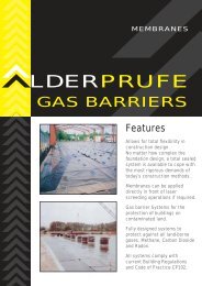
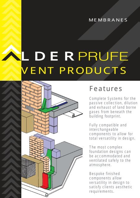
MEMBRANES<br />
LDERPRUFE<br />
VENT PRODUCTS<br />
Features<br />
Complete <strong>Systems</strong> for the<br />
passive collection, dilution<br />
and exhaust of land borne<br />
gases from beneath the<br />
building footprint.<br />
Fully <strong>com</strong>patible and<br />
interchangeable<br />
<strong>com</strong>ponents to allow for<br />
total versatility in design.<br />
The most <strong>com</strong>plex<br />
foundation designs can<br />
be ac<strong>com</strong>modated and<br />
ventilated safely to the<br />
atmosphere.<br />
Bespoke finished<br />
<strong>com</strong>ponents allow<br />
versatility in design to<br />
satisfy clients aesthetic<br />
requirements.
<strong>Vent</strong>ilation <strong>Systems</strong><br />
Introduction<br />
Background to Gas<br />
Protection Design<br />
The principal constituents of landfill gas are<br />
methane and carbon dioxide. Waste<br />
Management Paper No 27 provides information<br />
on the hazards of methane and carbon dioxide<br />
when present in confined spaces. Methane can<br />
form flammable and potentially explosive<br />
mixtures in air when ignited. The flammable or<br />
explosive range of methane is between 5% to<br />
15% by volume in air. The concentration limits<br />
are <strong>com</strong>monly known as the "Lower Explosive<br />
Limit" (LEL) and the "Upper Explosive Limit"<br />
(UEL) respectively. Concentrations above the<br />
UEL should not be considered safe because<br />
dilution with air will cause the <strong>com</strong>position to fall<br />
within the flammable range. The presence of<br />
Carbon Dioxide will affect<br />
the flammable range of<br />
methane but not unl<strong>ess</strong><br />
present in significant<br />
concentrations. Methane<br />
can also act as an<br />
asphyxiant either alone or<br />
when mixed with air,<br />
when the oxygen content<br />
is depleted. A<br />
concentration of greater<br />
than 1% methane in a<br />
confined space is<br />
considered hazardous in<br />
Waste Management<br />
Paper No.27.<br />
Carbon Dioxide affects<br />
the respiration and<br />
central nervous systems<br />
at concentrations greater than 0.5% by volume<br />
in air. It can cause unconsciousn<strong>ess</strong> leading to<br />
death at concentrations greater than 10% to<br />
15% by volume in air. Waste Management<br />
Paper No 27 considers that carbon dioxide is a<br />
hazard to health at concentrations greater than<br />
1.5% by volume in air, at which level evacuation<br />
of an affected area is re<strong>com</strong>mended.<br />
The Building Regulations Approved Document<br />
Part C2 gives guidance for methane and carbon<br />
dioxide concentrations in the ground with<br />
respect to new development. Gas protection<br />
measures are considered nec<strong>ess</strong>ary where the<br />
concentrations of methane and/or carbon<br />
dioxide exceed 1% and 1.5% by volume in air<br />
respectively, although the Building Regulations<br />
give little guidance on the scope of protection<br />
measures required for different gas regimes.<br />
There are many techniques to protect<br />
development from methane and associated<br />
gases. Each measure has its own advantages<br />
and disadvantages and may be more suitable in<br />
certain situations and types of development.<br />
Furthermore no protective measure on its own<br />
is immune from factors unknown to or out of the<br />
control of the designer. Such factors might lead<br />
to failure and for this reason it is normal practice<br />
to <strong>com</strong>bine individual protection measures to<br />
form a gas control system. In this way the<br />
probability of failure or of gas passing each<br />
individual protection measure in the system is<br />
minimised.<br />
The provision of gas protection measures<br />
should be based on a <strong>com</strong>prehensive desk<br />
study, ground investigation and gas<br />
monitoring, including measurement of<br />
borehole flow rates. This will help<br />
identify ground conditions,<br />
potential source(s) of<br />
gas, migration<br />
pathways and<br />
generation potential.<br />
The level risk may<br />
then be ass<strong>ess</strong>ed<br />
and an appropriate<br />
gas protection<br />
system designed. Account<br />
should be taken of the sensitivity<br />
of the proposed end use.<br />
Underfloor ventilation should be<br />
designed following the guidance provided by<br />
the Partners in Technology Research Report,<br />
Passive <strong>Vent</strong>ing of Soil Gases Beneath<br />
Buildings, and also British Standard BS5925:<br />
1991<br />
Latest independent design guidance<br />
provided in the Department of Environment<br />
- Passive <strong>Vent</strong>ing of Soil Gases Beneath<br />
Buildings - Research Report advises the<br />
following:<br />
The first gas protection measure beneath<br />
buildings is the gas dispersal layer, which<br />
should be designed to dilute ground gas(es)
Introduction<br />
Action of wall vent. On an isolated building , wind forces exert pr<strong>ess</strong>ures greater than current<br />
atmospheric pr<strong>ess</strong>ure on its windward side and lower pr<strong>ess</strong>ure on its leeward side creating suction.<br />
Increasing the number of wall vents will enhance cross-wall ventilation.<br />
below the designed target equilibrium<br />
concentration(s) and disperse the gas(es)<br />
safety beyond the building footprint.<br />
The gas resistant membrane acts as an<br />
additional protection to the dispersal system.<br />
The principal function of the barrier is to prevent<br />
gases entering the building through the floor<br />
slab during periods when air movement is<br />
insufficient to develop the desired dilution and<br />
dispersal levels. These still-air conditions may<br />
occur due to natural nil-wind situations for<br />
passive systems, or mechanical breakdown of<br />
active systems.<br />
The design of the gas dispersal layer should<br />
take into account the fill-time, i.e. the time<br />
required for the dispersal layer to reach target<br />
gas concentration thresholds during still-air<br />
conditions. The fill-time is a function of the<br />
porosity of the ventilation medium, gas<br />
concentration and gas emission rate.<br />
Wind<br />
Wind is usually the principal driving force for<br />
dilution and dispersion of gas within a sub-floor<br />
ventilation layer. Wind movement around<br />
buildings creates areas of higher pr<strong>ess</strong>ure (on<br />
the windward side) and areas of lower pr<strong>ess</strong>ure<br />
(on the leeward side). This causes a pr<strong>ess</strong>ure<br />
gradient across the ventilation layer. Under<br />
steady state conditions fresh air enters the<br />
ventilation layer on the windward side and<br />
migrates through the layer, exiting on the<br />
leeward side mixed with soil gas intercepted by<br />
the layer. For responsive ventilation layers (such<br />
as voids) wind induced pr<strong>ess</strong>ure driven flow is<br />
reasonably approximated by steady state<br />
assumptions, particularly for moderate wind<br />
speeds. However, for l<strong>ess</strong> permeable media<br />
(such as gravels), steady state pr<strong>ess</strong>ure driven<br />
flow is an over simplification, only<br />
developing with sustained periods of wind from<br />
the same general direction.<br />
Principles of design<br />
To achieve passive venting a void is formed<br />
between the building and underlying ground.<br />
The void is connected to the external<br />
envelope of the building by vents. The<br />
principle of passive venting beneath a<br />
building is illustrated in figure 29. It should<br />
be noted that where the surface emission rate,<br />
q, is from a <strong>com</strong>bination of gaseous<br />
contaminants, e.g. methane, carbon dioxide<br />
and the other associated gases, then the<br />
required volume flow rate of fresh air, Q, should<br />
be calculated on the basis of the individual<br />
emission rate for each gas <strong>com</strong>ponent. A<br />
fundamental problem in designing a passive<br />
venting system arises in quantifying the<br />
parameters:<br />
concentration, c, of each gas <strong>com</strong>ponent<br />
entering the void space.<br />
surface emission rate into the void space,<br />
q, of each gas <strong>com</strong>ponent.<br />
From BS 5925: 1991, Q, is given by the formula<br />
<strong>Vent</strong>ilation <strong>Systems</strong>
<strong>Vent</strong>ilation <strong>Systems</strong><br />
Introduction<br />
Q = q<br />
Figure 1<br />
[<br />
100 - C e<br />
]<br />
C e<br />
where q = the surface emission rate of<br />
the particular gas contaminant<br />
into the void.<br />
ce = the concentration of the gas<br />
contaminant at the equilibrium,<br />
i.e. the designed safe<br />
acceptable concentration.<br />
Gas contaminant entering<br />
a ventilated space<br />
Advice given allows a designer to provide<br />
adequate ventilation to any building<br />
development for habitable purposes. All<br />
habitable buildings have a capacity to dilute any<br />
ingr<strong>ess</strong> of gas, thus providing a margin of<br />
safety. Risk will arise if:-<br />
Concept<br />
The concept of the passive dilution barrier is to<br />
form a low pr<strong>ess</strong>ure area relative to the<br />
surrounding gassing ground, to encourage gas<br />
to flow towards the barrier. This is achieved by<br />
driving discrete vent nodes into the ground,<br />
which are connected to a collection/dilution duct<br />
running along the top of the strips. The nodes<br />
<strong>com</strong>prise highly efficient geo<strong>com</strong>posite strips.<br />
The duct had a high flow of fresh air through it<br />
by means of passive ventilation. This is one of<br />
the key advantages of the system as it:-<br />
dilutes gas emissions to tolerable levels<br />
reduces pr<strong>ess</strong>ure and causes a suction<br />
effect in the geo<strong>com</strong>posite vent nodes,<br />
which enhances gas flow from the ground<br />
towards the vents.<br />
<strong>Vent</strong>ilation of the duct can be achieved using a<br />
<strong>com</strong>bination of vent stacks, bollards or ground<br />
level boxes, depending on the gas regime and<br />
wind conditions at a a particular site.<br />
there is a confined space in the building<br />
which is inadequately ventilated<br />
the rate of ingr<strong>ess</strong> of gas is sufficiently<br />
high to render dilution and dispersion by<br />
natural ventilation inadequate.<br />
Given the inherent difficulties of being able to<br />
measure and predict gas levels with any<br />
certainty, it is best practice to endeavour to<br />
dilute the gas before it can enter the building.<br />
This is achieved by providing passive venting<br />
between the building and the underlying ground<br />
to dilute and disperse any emission of gas.<br />
The system, is particularly effective where gas<br />
migration is occurring through shallow layers of<br />
sand and gravel up to 5m depth, underlain by<br />
an impermeable layer. This is typical of many<br />
situations encounted in the UK. the nodes can<br />
be installed to a maximum depth of 5m below<br />
starting level. The starting level can be in<br />
trenches up to 3m depth, giving maximum<br />
effective depth of 8m. As the depth of the<br />
migration pathway increases below the toe of<br />
the nodes the barrier be<strong>com</strong>es l<strong>ess</strong> effective.
Geo-Void <strong>Systems</strong><br />
GEO VOID 12mm 25mm 25mm 80/100* 52mm* 52mm* 52mm* 100mm*<br />
Strips Blanket x 260mm x x480mm Blanket Blanket<br />
Pr<strong>ess</strong>ure Resistance 400KN 400KN 400KN 33KN/m 1457KN/m 1457KN/m 1457KN/m 400KN/m<br />
Permeability<br />
Flow Rate<br />
Gas Methane Emission<br />
Regime Conc. Rate1 INDUSTRIAL AND COMMERCIAL DEVELOPMENTS<br />
(%v/v) (m/s)<br />
A 5 1 0.005 ✔ ✔ ✔ ✔ ✔ ✔ ✔ ✔<br />
B 5 0.005 - ✔ ✔ ✔ ✔ ✔ ✔ ✔<br />
C 5 0.01 - - ✔ ✔ ✔ ✔ ✔ ✔<br />
D 20 0.005 - - - - ✔ ✔ ✔ ✔<br />
E 20 0.01 - - - - - - ✔ ✔<br />
F 20 0.05 - - - - - - With Active Upgrade<br />
Housing - - ✔ ✔ ✔ ✔ ✔ ✔ ✔ ✔<br />
Including regime<br />
without Active System<br />
* Based on normal side ventilation.<br />
Additional side ventilation provisions can improve the gas characteristic<br />
CONFORMING REFERENCES<br />
CONFORMING REFERENCES<br />
The Building Regulations 1991,<br />
Approved Document C : Site Preparation<br />
and Resistance to Moisture.<br />
NHBC Standards, Chapter 5.1<br />
Substructure and Ground Bearing Floors.<br />
BS 8000 : Part 4 : 1989, Workmanship<br />
on Building Sites: Code of Practice for<br />
Waterproofing.<br />
BS 8102 : 1990, Code of Practice for<br />
Protection of Structures Against Water<br />
from the Ground.<br />
BRE Report 211, Radon: Guidance<br />
on Protective Measures for New<br />
Dwellings, 1991.<br />
BRE Report 212, Construction of New<br />
Buildings on Gas Contaminated Land.<br />
BRE Report, Radon Sumps: BRE Guide<br />
to Radon Remedial Measures in Existing<br />
Dwellings, 1992.<br />
Basic guidance only<br />
NRPB Report R272, Exposure to radon<br />
in UK Dwellings, 1994.<br />
CIRIA Report 149, Protective<br />
Development from Methane, 1995.<br />
BRE Good Building Guide 25, Buildings<br />
and Radon, 1996.<br />
Building Standards (Scotland),<br />
Regulations 1990 - Part G.<br />
Building Regulations (Northern<br />
Ireland), 1990 - Part C.<br />
Ove Arup & Partners, 1997 - Passive<br />
<strong>Vent</strong>ing of Soil Gas Beneath Buildings.<br />
Partners in Technology Research Report.<br />
Department of the Environment and The<br />
Welsh Office (1992).<br />
DOE Partners in Technology.<br />
<strong>Vent</strong>ilation <strong>Systems</strong>
<strong>Vent</strong>ilation <strong>Systems</strong><br />
Aldervent Vertiduct System<br />
For sites with high levels of gas<br />
production, larger vent stacks are inserted<br />
410mm x 460mm. These are pre-fabricated<br />
and lined upto 15metres in depth,<br />
individually vented or joined in series as<br />
with the standard systems.<br />
Concept<br />
The concept of the passive dilution barrier is to<br />
form a low pr<strong>ess</strong>ure area relative to the<br />
surrounding gassing ground, to encourage gas<br />
to flow towards the barrier. This is achieved by<br />
driving discrete vent ducts into the ground,<br />
which are connected to a collection/dilution duct<br />
running along the top of the strips. The ducts<br />
<strong>com</strong>prise highly efficient geo<strong>com</strong>posite strips or<br />
cells. The duct had a high flow of fresh air<br />
through it by means of passive ventilation. This<br />
is one of the key advantages of the system as it:-<br />
dilutes gas emissions to tolerable levels<br />
reduces pr<strong>ess</strong>ure and causes a suction<br />
effect in the geo<strong>com</strong>posite vent nodes,<br />
which enhances gas flow from the ground<br />
towards the vents.<br />
<strong>Vent</strong>ilation of the duct can be achieved using a<br />
<strong>com</strong>bination of vent stacks, bollards or ground<br />
level boxes, depending on the gas regime and<br />
wind conditions at a a particular site.<br />
The system, is particularly effective where gas<br />
migration is occurring through shallow layers of<br />
sand and gravel up to 5m depth, underlain by<br />
an impermeable layer. This is typical of many<br />
situations encounted in the UK. the nodes can<br />
be installed to a maximum depth of 5m below<br />
starting level. The starting level can be in<br />
trenches up to 3m depth, giving maximum<br />
effective depth of 8m. As the depth of the<br />
migration pathway increases below the toe of<br />
the ducts, the barrier be<strong>com</strong>es l<strong>ess</strong> effective.<br />
Installation<br />
The passive dilution barrier is installed using<br />
a no dig method in which a steel mandrel is<br />
vibrated up to 5m into the ground, using a<br />
vibrating piling hammer. Once the hollow<br />
mandrel is in the ground the Geo-void 30 or<br />
Geo-void 52 pre-wrapped strip inserted, the<br />
mandrel is then withdrawn, leaving the vent in<br />
the ground.<br />
The key advantages of this method of<br />
installation are:<br />
speed - up to 30 vents per day can be<br />
installed,<br />
cost - there is a reduction in excavation<br />
costs and disposal of spoil that is<br />
frequently contaminated,<br />
safety - contact with contaminated<br />
materials by the installers is minimised.<br />
A further advantage is that walls can be<br />
constructed very close to site boundaries and in<br />
areas where acc<strong>ess</strong> is restricted and<br />
conventional barriers could not be constructed.
Aldervent Geo-Void 100/96<br />
Gas collection channels and cells for the<br />
dilution and dispersion of land borne gases to<br />
atmosphere<br />
Benefits<br />
The only void channel/pipe to meet and exceed<br />
the Department of the Environment Partners in<br />
Technology' requirement for gas regime<br />
modelling.<br />
(I.e. all flow rate calculations based on<br />
minimum 20% perforation).<br />
Simple and Quick to install<br />
No Maintenance Costs<br />
Simple Connection to Pits and Pipes<br />
Economical, Ecological<br />
Application<br />
The geo-void channel section is<br />
laid in top granular layer or<br />
blinding layer. Encased in high<br />
strength Geo-tex filter mat, the<br />
geo-void creates clear and open<br />
pathways to attract gases from<br />
the ground, mix them with<br />
in<strong>com</strong>ing air and disperse the<br />
diluted gases to atmosphere.<br />
Features<br />
Alderprufe GRA Gas Barrier membrane<br />
The most efficient sub-soil pipe in the world<br />
providing an ecological solution to land gas<br />
management<br />
Lightweight<br />
Very High Infiltration Rate -<br />
85% perforation area<br />
96% Void Ratio<br />
High Flow Rate<br />
Modular<br />
Robust - 33.5 KN Crush strength<br />
(Direct load on 80mm surface)<br />
Size - 80 x lOOmm x 3 .15mtrs filter wrapped<br />
Aldercourse GRA<br />
Gas Barrier DPC<br />
Aldervent<br />
Ground level<br />
<strong>Vent</strong> Unit<br />
<strong>Vent</strong>ilation <strong>Systems</strong><br />
Laid at pre-determined centres<br />
to suit the gas regime required.<br />
Aldervent Geo-void channels<br />
are connected through the<br />
perimeter edge detail by a series<br />
of modular units to suit the<br />
foundation and building design.<br />
Geo-Void 100/80 Channel<br />
Alderseal gastite Mastic to reinforcement
<strong>Vent</strong>ilation <strong>Systems</strong><br />
Aldervent Geo-Void 26/60<br />
The purpose of any ventilation system<br />
below the structure is to prevent high<br />
concentrations of land borne gas<br />
Methane, Carbon Dioxide or Radon -<br />
accumulating, thus preventing a<br />
potential health and safety risk.<br />
The main criteria for the Aldervent<br />
designed ventilation systems are:<br />
To dilute the gas concentrations<br />
present with the through flow of air<br />
from the perimeters of the building.<br />
To disperse any gas safety along<br />
pre-determined voids and<br />
channels to the outside<br />
atmosphere, where it will be safely<br />
diluted and dispersed into<br />
the atmosphere.<br />
Description<br />
Aldervent Geo-void 26/60 is a preformed void<br />
forming sheet system, installed in one operation<br />
to either cover the whole of the building footprint<br />
as a blanket or laid in strip form at design<br />
determined centres. Installed on top of the<br />
granular sub-base below the structural slab.<br />
Installed with the geo-textile filter membrane on<br />
the underside creating a 26mm clear void space<br />
for the dilution and dispersal of gases. With an<br />
intrinsic permeability of at least 1.2 x 10.5, high<br />
pr<strong>ess</strong>ure resistance being created by the<br />
studded pattern. The geo-textile filter layer<br />
allows gas to filter into the void but prevents<br />
clogging.<br />
Aldervent Geo-grid 26 is connected into slotted<br />
gas collection ducts at opposing perimeters.<br />
The gas collection duct is then connected at<br />
pre-determined centres (dependent on the site<br />
investigation report and percentage target<br />
Aldercourse GRA<br />
Heat Bonded to Toe<br />
Ground Level <strong>Vent</strong> Box<br />
150mm<br />
GeoTex 300PP Protection Mat<br />
Alderprufe GRA<br />
Reinforced Concrete Raft<br />
Aldervent Geo-Void Blanket<br />
Sand Blinding
Aldervent Geo-Void 26/60<br />
Specification<br />
Aldervent Geo-void 26/60 gas dispersal mat is to be<br />
installed strictly as per manufacturers<br />
re<strong>com</strong>mendations and in accordance with good<br />
building practice.<br />
Aldervent Geo-void 26/60 has been CFD modelled in<br />
line with re<strong>com</strong>mendations and tests undertaken for the<br />
DOE Partners in Technology report Passive <strong>Vent</strong>ing of<br />
Soil Gases Beneath Buildings Research Report Design<br />
Guide 1997.<br />
All test results are available for engineers ass<strong>ess</strong>ment<br />
and design calculation checks on request.<br />
Where developments are considered on sites with<br />
extremely high gas emission figures, active upgrade<br />
and gas monitoring systems can be attached to the<br />
designed passive systems if required<br />
Technical Data<br />
Properties Test Method Unit Value<br />
FILTER FABRIC<br />
Tensile strength<br />
Strip bst 20cm BS6096-1 kN/m 8.2<br />
Elongation at<br />
max load 35% 45<br />
At 5% elongation BS6096 kN/m 3.35<br />
Wide width 50cm NF-G38-014 kN/m 8.8<br />
Elongation at<br />
max.load 31% 43<br />
Grab strength DIN S 3858 N 565<br />
Grab strength ASTM 1682 N 700<br />
mod 200mm<br />
Elongation at<br />
max load >60% >60<br />
Puncture resistance ~CBR)<br />
Max. Ioad BS6°wn6/4 N 1270<br />
Displacement mm 50<br />
<strong>Vent</strong>ilation <strong>Systems</strong><br />
Burst strength AsTM D-3786 kN/m 2 1350<br />
equilibrium required for the structure) to a series of<br />
ventilation inlets and outlets.<br />
Dependent on the design criteria and air flow rates<br />
required, these can be Aldervent through wall vent<br />
units, vent bollards, ground level vent boxes,<br />
vertical risers (see separate data sheets)<br />
When installed as a blanket this provides a<br />
clear prepared surface for the direct installation<br />
of an Alderprufe proprietary Gas Barrier<br />
membrane. (see separate data sheets)<br />
Trapeziodial Tear<br />
Strength ASTM D-1117 N 370<br />
Core<br />
Nominal<br />
Thickn<strong>ess</strong><br />
26mm<br />
Material<br />
HDPE<br />
Crush / res @ ASTM<br />
10% deflwti D 1621 - 73 kN/m 400 (min)<br />
mean @ yield<br />
Creep resistance<br />
200 KPA for<br />
100 hrs % 5 (max)<br />
Forchelmer DoE approved s/m
<strong>Vent</strong>ilation <strong>Systems</strong><br />
Aldervent Geo-Void 52/96<br />
Specifically designed and manufactured to<br />
create large flow void space below structures<br />
constructed on contaminated land where landfill<br />
gas is a potential hazard<br />
Aldervent Geo-void 52/96 is designed to be<br />
installed below the structural slab in or on top of<br />
the formation layer.<br />
Features<br />
Light weight heavy duty, 96% void matrix<br />
Quick and simple to install<br />
No maintenance cost<br />
Economic and Ecologically friendly<br />
Simple connections to all Aldervent<br />
inlet/outlet units.<br />
Extremely high infiltration and flow<br />
rate capability<br />
High Load Capacity<br />
to enable direct loading<br />
by site traffic<br />
provide an extremely strong heavy load bearing<br />
void former that once installed is more than<br />
capable of supporting site traffic for slab<br />
installations (i.e. concrete wagons, laser pour<br />
vehicles).<br />
Description<br />
When installed as a blanket the Geo-void 52/96<br />
is overlaid with Geotex 225 filter membrane<br />
prior to the installation of the gas barrier<br />
membrane or the structural slab.<br />
When installed in strip form in either 260mm<br />
wide or 480mm wide lengths (or multiples<br />
thereof) the Geo-void 52/96 is supplied<br />
pre-wrapped in Geotex filter fabric and installed<br />
at designed centres in the formation layer.<br />
Description<br />
Aldervent Geo-void 52/96 is a void forming<br />
modular system installed in one operation to<br />
either cover the whole of the building footprint<br />
as a blanket or laid in strip form at design<br />
determined centres.<br />
The unique modular design and clipping system<br />
At perimeters of foundations the Geo-void<br />
52/96 is connected to inlet and outlet gas<br />
collection systems. Dependent on the design<br />
criteria and air flow rates required, these can be<br />
Aldervent Thru-wall <strong>Vent</strong> Units, <strong>Vent</strong> Bollards,<br />
Ground Level <strong>Vent</strong> Boxes, Vertical risers or slim<br />
vents<br />
(see separate data sheets)
Aldervent Geo-Void 52/96<br />
Technical Data<br />
GEO-VOID 52/96<br />
Size of modules<br />
Filter wrapped strips<br />
480mm x 260mm x 52mm<br />
3.12mt x 480mm x 52mm<br />
3.36mt x 260mm x 52mm<br />
Loading/Crush Strength 1457.6 kN/m 2<br />
Material<br />
100% Polypropylene<br />
Void Ratio/Porosity 96% 3D matrix<br />
Intrinsic Permeability<br />
(K(m 2 ) 2.4 x 10 -4<br />
Clear void space equivalent<br />
GEOTEX 225<br />
Filter fabric<br />
44.7mm<br />
see separate data<br />
Where developments are considered on sites<br />
with extremely high gas emission figures active<br />
upgrades and gas monitoring systems can be<br />
attached to the designed passive systems if<br />
required.<br />
It should be noted that due to Geo-void<br />
52/96 unique void ratio and flow capability,<br />
passive systems in strip form are more<br />
efficient than many blanket void systems<br />
designed. This makes Geo-void 52/96<br />
extremely cost efficient and economical in<br />
use.<br />
<strong>Vent</strong>ilation <strong>Systems</strong><br />
Aldervent Geo-void 52/96 allows for the rapid<br />
dilution and safe dispersal of land borne gases<br />
from beneath the building footprint, allowing for<br />
<strong>com</strong>plete flexibility in foundation design.<br />
Aldervent Geo-void 52/96 has been CFD<br />
modelled in line with re<strong>com</strong>mendations and<br />
tests undertaken for the DOE Partners in<br />
Technology report "Passive <strong>Vent</strong>ing of Soil<br />
Gases Beneath Buildings Research report<br />
Design Guide 1997".
<strong>Vent</strong>ilation <strong>Systems</strong><br />
Aldervent Geo-Void 52/96<br />
Installed as a full blanket to<br />
cover the footprint of the<br />
building, the Geo-void 52/96<br />
void forming 3d matrix provided<br />
a totally unique high<br />
permeability, high flow rate,<br />
high strength medium for the<br />
safe dilution and dispersal to<br />
atmosphere of all land borne<br />
gases from beneath the<br />
footprint of any structure, even<br />
when considerations for high<br />
emitting gas volumes have to<br />
be calculated.<br />
Geo-void 52/96 extremely high<br />
1400kN/m2 crush strength make<br />
it the ideal solution to under slab venting on<br />
fast-track operation sites, particularly when<br />
laser pouring vehicles and the laser pouring<br />
machines.<br />
Geo-void is more than capable of absorbing<br />
the loading from both the concrete vehicles<br />
and the laser pouring machines.<br />
Geo-void 52/96 unique void ratios create a<br />
large volume airflow gas for the rapid dilution<br />
and dispersal of land borne emitting gases.<br />
Easily connected to the Aldervent perimeter<br />
gas collection system and the appropriate<br />
inlet and outlet connections available (see<br />
separate data), dependent on volume flow<br />
Geo-void 52/96 in-built clipping system<br />
creates an extremely stable robust base and<br />
figures required and site-specific aesthetics<br />
required.<br />
platform for following trades to work on with<br />
no lateral movement from the system.
Aldervent Geo-Void 100<br />
Designed to allow for sufficient through flow of<br />
air below the perimeter of the building to<br />
enable sufficient dilution of potentially<br />
dangerous ground emitting gas even on active<br />
gassing sites.<br />
The Geo-void 100 ventilation blanket creates a 99<br />
mm clear equivalent void space beneath the<br />
footprint of the building. Flow of air from<br />
atmosphere through the blanket and expulsion<br />
through calculated outlets is increased and<br />
enhanced by the unique leg support design.<br />
Preventing build up of dead pots and the creation<br />
of no flow calm areas created by natural<br />
turbulence and the effects of buoyancy in total<br />
clear large void areas.<br />
The overall depth of 150 mm reduces the need for<br />
large volume fill removed to ac<strong>com</strong>modate the<br />
void space.<br />
Full CFD (Computation Fluid Dynamics) modelling<br />
has been undertaken conforming to the Partners<br />
in Technology re<strong>com</strong>mendations.<br />
Due to the large void space created on very active<br />
high flow sites active extraction systems can be<br />
attached easily and economically to allow for high<br />
volume controlled gas expulsion.<br />
The Geo-void 100 system is available in a number<br />
of leg formations dependent on site specific<br />
requirements and structural nec<strong>ess</strong>ity.<br />
Foundation - Two-leg elements Geometry<br />
our Products Liability and Warranty system.<br />
Foundation - Six-feet elements Geometry<br />
<strong>Vent</strong>ilation <strong>Systems</strong><br />
The resultant footprint blanket creates a flat<br />
finished surface for the installation of a suitable<br />
gas barrier membrane and construction of the<br />
finished floor slabs.<br />
Geo-void 100 ventilation system is supplied as<br />
part of a total underfloor ground ventilation and<br />
barrier system and is only available as a<br />
<strong>com</strong>ponent of an Alderburgh Accredited system<br />
installed by trained operatives and covered under<br />
Foundation - Six-leg elements Geometry<br />
Technical Details 1200 x 1200 x 150 mm overall dimension<br />
Leg formation<br />
to suit site requirements<br />
Loading Dependent on site requirement 30kN/m2 - 1400k/m 2
<strong>Vent</strong>ilation <strong>Systems</strong><br />
Geo-Void <strong>Systems</strong><br />
Aldervent Geo Grid 26<br />
@ 3mtr c/s<br />
Alder Geo Void 160/200<br />
Aldervent Collector Pipe<br />
Aldervent Collector ‘T’<br />
Aldervent Ground<br />
Level <strong>Vent</strong> Unit
<strong>Vent</strong> Products<br />
Air Brick <strong>Vent</strong> AVAB<br />
The vent is used in <strong>com</strong>bination.with a cavity<br />
sleeve (AVAS or AVPS) through-the-wall<br />
ventilation with a high airflow capacity. The vent<br />
has been designed to match standard brick face<br />
dimensions, and has integral mortar grips.<br />
<strong>Vent</strong>ilation area: 6000mm 2 .<br />
Colours: terracotta, buff or anthracite black.<br />
Adjustable Periscope<br />
Sleeve AVPS<br />
The Airbrick periscopic sleeve AVPS is<br />
designed to attach to the Airbrick vent AVAB to<br />
provide effective and permanent ventilation<br />
beneath suspended and solid timber and<br />
concrete ground floors. The periscopic design<br />
allows the suspended floor to be at or below<br />
surrounding ground level, thereby saving on<br />
brickwork in construction, and gives vertical<br />
adjustment for 3 to 4 brick courses. The lower<br />
end is protected by a 9mm grille. It provides a<br />
clear airway which cannot be blocked by mortar<br />
and will bridge cavities from 50 to 100mm. The<br />
sleeve joint may be sealed with tape if<br />
nec<strong>ess</strong>ary.<br />
AVPA<br />
AVAS<br />
AVPS<br />
AVAS<br />
<strong>Vent</strong> Pipe<br />
Adaptor AVPA<br />
The <strong>Vent</strong> pipe adaptor AVPA<br />
enables a standard 100mm<br />
internal diameter pipe to be<br />
connected to sleeves and/or<br />
ventilators, so that remote<br />
areas of underfloor voids may<br />
be ventilated. The adaptor<br />
can be attached directly to the<br />
vent AVAB, sleeve periscope<br />
AVPS or the straight<br />
adjustable sleeve AVAS.<br />
Joints may be sealed with<br />
tape if nec<strong>ess</strong>ary.<br />
Underfloor<br />
Void <strong>Vent</strong><br />
Sleeve AVAS<br />
As an addition to the through<br />
wall product range,<br />
Alderburgh offer the new<br />
AVAS extension sleeve to<br />
adapt its telescopic<br />
Underfloor Void <strong>Vent</strong>.<br />
The AVPS Underfloor<br />
<strong>Vent</strong>ilator already telescopes<br />
vertically to fit three to five<br />
brick courses but now the<br />
AVAS means a further two<br />
course adjustment per<br />
extension sleeve is possible.<br />
<strong>Vent</strong>ilation <strong>Systems</strong><br />
AVPS<br />
As well as making infinite<br />
vertical extension possible the<br />
AVAS has been cleverly<br />
designed to fit the base of the<br />
telescopic vent thus enabling<br />
horizontal expansion through<br />
larger cavities by 185mm per<br />
unit.
<strong>Vent</strong>ilation <strong>Systems</strong><br />
<strong>Vent</strong> Products<br />
Aldervent<br />
<strong>Vent</strong>ilation Bollards<br />
Description<br />
Designed to allow air to pass in or out of the<br />
gas ventilation system. The use of <strong>Vent</strong>ilation<br />
Bollards allows considerable flexibility in<br />
design without having to <strong>com</strong>promise<br />
foundation requirements<br />
Many options both in design and materials<br />
used are available dependent on design<br />
requirements, position of bollards and<br />
aesthetic needs.<br />
Installed against the building the bollards are<br />
fabricated out of plastic. If free-standing and<br />
particularly in trafficked areas the bollards<br />
are either galvanised steel or stainl<strong>ess</strong> steel.<br />
Free ventilation airflow space can be<br />
adjusted to suit ventilation design regime i.e.<br />
typically 3000mm 2 - I8000mm 2 per unit are<br />
achievable.<br />
Designs out of plastic with steel anchoring<br />
inserts can also be utilised, particularly if the<br />
requirements are to match and blend with<br />
bollard designs as part of a projects hard<br />
landscaping.<br />
Data<br />
Dimensions and design to suit specific<br />
projects.
Aldervent<br />
Ground Level <strong>Vent</strong> Units<br />
Manufactured from inert PP UW stable<br />
<strong>com</strong>pound. The Aldervent ground vent<br />
system is <strong>com</strong>pletely modular allowing for a<br />
variety of free air/gas spaced flow rates<br />
dependent on the construction, design and<br />
gas flow requirements.<br />
Minimum flow rate per unit 6000 square mm up<br />
to 72,000 square mm per unit.<br />
Design re<strong>com</strong>mended centres dependent on<br />
airflow required.<br />
A preformed 96% voided slim unit for fixing<br />
against the external perimeter of the<br />
building at ground level.<br />
Specifically designed to be unobtrusive in<br />
positions where regular acc<strong>ess</strong> is required<br />
to outside perimeter by pedestrian or<br />
vehicular traffic.<br />
Completely<br />
modular in design,<br />
the system can be<br />
installed with the<br />
modular collection<br />
duct in the vertical<br />
plane. Brought to<br />
the ground surface<br />
for atmospheric<br />
venting at design<br />
determined<br />
centres.<br />
Physical Properties<br />
Wall Thickn<strong>ess</strong><br />
Crush Resistance<br />
In plane flow<br />
30mm<br />
600KN/ square m<br />
Open Void Space<br />
Unit size 400 x 220 x 450<br />
400 x 440 x 450<br />
400 x 660 x 450<br />
Supplied with perforated plastic or stainl<strong>ess</strong><br />
steel top.<br />
Aldervent Slim <strong>Vent</strong><br />
Physical Properties<br />
Dimensions<br />
Depth<br />
Crush Resistance<br />
52mm wide x any<br />
length in multiples<br />
of 480mm<br />
Any depth by<br />
multiples of 260mm<br />
1400KN/ square m<br />
Porosity 96%<br />
Top Cover<br />
Stainl<strong>ess</strong> steel<br />
perforated<br />
<strong>Vent</strong>ilation <strong>Systems</strong>
<strong>Vent</strong>ilation <strong>Systems</strong><br />
Aldervent<br />
High Level Risers<br />
Installed against the external wall of the<br />
building - terminating at least 600mm above<br />
eaves level, or installed free standing in the<br />
surrounding ground away from the building.<br />
Riser pipe is between 110mm - 240mm<br />
diameter dependent on flow volume and rate<br />
required. Manufactured out of Plastic,<br />
Galvanised or Stainl<strong>ess</strong> Steel pipe.<br />
Terminating with a rotating spiromatic cowl<br />
manufactured from stainl<strong>ess</strong> steel, the<br />
characteristics of which are as follows:-<br />
Support<br />
A stainl<strong>ess</strong> steel support fitted<br />
with stainl<strong>ess</strong> screws 18/8 which adapts<br />
easily to all types of vertical riser pipe;<br />
Pivot<br />
A pivot, mounted on ball bearings, specially<br />
designed to resist extremes of temperature;<br />
the system is enclosed in a watertight area<br />
and protected by an oil seal;<br />
BODY<br />
Body<br />
A rotating body <strong>com</strong>posing an assembly of<br />
helicoidal blades, each blade rivetted to the<br />
circular base frame in stainl<strong>ess</strong> steel and<br />
copper for chemically aggr<strong>ess</strong>ive gases.<br />
Air Flow and Upstand Size determine the<br />
required model:<br />
Aspiromatic 100<br />
Stack Diameter: 80-100mm<br />
3-4 inches<br />
Airflow: 80 m 3 /h<br />
3,000 ft 3 /h<br />
Aspiromatic 160<br />
Stack Diameter: 80-160mm<br />
3-6 inches<br />
Airflow: 125 m 3 /h<br />
4,000 ft 3 /h<br />
Aspiromatic 200<br />
Stack Diameter: 112-200mm<br />
4.5-8 inches<br />
Airflow: 225 m 3 /h<br />
8,000 ft 3 /h<br />
Aspiromatic 240<br />
Stack Diameter: 150-240mm<br />
6-9.5 inches<br />
Airflow: 315 m 3 /h<br />
11,000 ft 3 /h<br />
NB: Figures for flow are calculated for wind<br />
speeds of 10-30km/h (6-18 mph)<br />
<strong>Vent</strong>ing increases<br />
volumes through flow<br />
creating passive<br />
draw-through of gas<br />
ventilation system from<br />
below the building.<br />
Connection on one side<br />
of perimeter with inlet<br />
of air through systemstatic<br />
altern-ative inlet<br />
units (ie. bollards,<br />
airbricks, grubs).<br />
Also supplied with antivandal<br />
gauge on<br />
exposed sites.
Radon Gas Sump<br />
Use<br />
To service evacuation of gas from below<br />
integrity shield.<br />
Introduction<br />
The gas reception sump when positioned<br />
below a floor slab (incorporating an integrity<br />
shield in the form of membranes and<br />
barriers), provides a passive gas exit route<br />
via a ventilation stack.<br />
Gas Reception Sump<br />
The gas reception sump is designed to be<br />
incorporated within the granular fill, beneath<br />
the floor slab. The reception sump receives<br />
gas from underneath the building and<br />
promotes passive discharge via a vertical<br />
110mm PVC ventilation stack.<br />
The stack is terminated above the roof finish<br />
with a tile/slate external roof ventilator.<br />
Suitable for new build or existing properties,<br />
the reception sump may service up to 250<br />
metres' floor area, positioned in the most<br />
central location to promote<br />
even/optimum evacuation.<br />
The sump has integral inhalation<br />
apertures and inlet/outlet<br />
portholes to permit spur<br />
connection to adjoining sumps<br />
should the size or layout of the<br />
property dictate.<br />
not influence an area exceeding 250 metre<br />
S2. Sumps should be positioned centrally<br />
and the serviced area should not exceed a<br />
distance from the sump of 15 metres.<br />
To promote maximum depr<strong>ess</strong>urisation, fill<br />
used underneath the slab around the sump<br />
should not contain exc<strong>ess</strong>ive fines. In<br />
calculating the performance of sub-floor<br />
depr<strong>ess</strong>urisation, it is assumed the water<br />
table is not high and that any measures to<br />
exhaust gases will not be influenced by the<br />
waterlogged/ flooded areas.<br />
Sizes<br />
Sump approximately 680 x 410 x 450mm<br />
plus porthole projections which permit<br />
connection to 110mm standard vent/stack<br />
pipe. Inhalation apertures exit ratio exceeds 4<br />
to 1 for optimum performance.<br />
<strong>Vent</strong>ilation <strong>Systems</strong><br />
A maximum of 5 reception<br />
sumps is permitted per<br />
110mm ventilation stack.<br />
Where appropriate and if<br />
nec<strong>ess</strong>ary, mechanical -<br />
extraction can be achieved by<br />
the introduction of a powered<br />
fan, sited in the roof space.<br />
Where sub-floor depr<strong>ess</strong>urisation<br />
is created using a gas<br />
reception sump, it is<br />
re<strong>com</strong>mended that the sump should
All Alderburgh products are<br />
manufactured to the highest<br />
quality, being subject to rigid<br />
quality control. However, the<br />
<strong>com</strong>pany cannot control conditions<br />
of application and use of its<br />
products, thus any warranty,<br />
written or implied, is given in good<br />
faith for materials only. Alderburgh<br />
Ltd will not accept any<br />
responsibility for damage or injury<br />
arising from storage handling,<br />
misapplication or misuse of its<br />
products. All transactions are<br />
subject to our standard condition<br />
of sale, copies of which are<br />
available on request.<br />
LDERBURGH<br />
Alderburgh Limited.<br />
Sladen Mill, Halifax Road, Littleborough, OL15 0LB.<br />
For Further Assistance Tel: 01706 374416, Fax: 01706 376785<br />
E&OE. Without Guarantee.<br />
email: sales@alderburgh.<strong>com</strong>