Back Corona in Electrostatic Precipitators: New Findings - isesp
Back Corona in Electrostatic Precipitators: New Findings - isesp
Back Corona in Electrostatic Precipitators: New Findings - isesp

You also want an ePaper? Increase the reach of your titles
YUMPU automatically turns print PDFs into web optimized ePapers that Google loves.
Dust Resistivity Measurement and Onset of<br />
<strong>Back</strong> <strong>Corona</strong> <strong>in</strong> <strong>Electrostatic</strong> <strong>Precipitators</strong><br />
Muhammad Majid<br />
Technical University<br />
Dortmund<br />
Germany<br />
Muhammad.Majid@bci.tudortmund.de<br />
Helmut Wiggers<br />
Technical University<br />
Dortmund<br />
Germany<br />
helmut.wiggers@tudortmund.de<br />
Peter Walzel<br />
Technical University<br />
Dortmund<br />
Germany<br />
peter.walzel@bci.tudortmund.de<br />
1 Summary / Abstract:<br />
Electrical resistivity of the dust, to be separated <strong>in</strong> an electrostatic precipitator, is an important<br />
parameter from the design and operation po<strong>in</strong>t of view. It gives the knowledge about the onset of the<br />
back corona <strong>in</strong> the system. In-situ measurements can be performed us<strong>in</strong>g a resistivity measurement<br />
probe. But mostly it is done <strong>in</strong> the laboratories us<strong>in</strong>g a measurement apparatus and the dust sample<br />
collected from the hopper beneath the precipitator. A laboratory setup will be <strong>in</strong>troduced to measure<br />
the dust resistivity us<strong>in</strong>g a new method. Here, the onset of back corona can be detected directly dur<strong>in</strong>g<br />
the experiment which can be elim<strong>in</strong>ated immediately from the system by reduc<strong>in</strong>g the current by<br />
controll<strong>in</strong>g the supplied voltage. Experiments were performed with a fly ash sample with 11µm and<br />
four glass samples with 75, 112, 278 and 394 µm mean particle sizes. Results will be presented and<br />
discussed about the <strong>in</strong>fluence on resistivity results of dust resistivity measurement method: po<strong>in</strong>t-plate<br />
and plate-plate, mode of temperature variation: ascend<strong>in</strong>g and descend<strong>in</strong>g, air temperature, particle<br />
size and air humidity. F<strong>in</strong>ally, the visualization of back corona <strong>in</strong> such systems will be presented.<br />
2 Introduction<br />
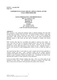
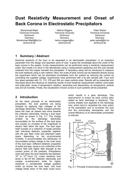
As the basic pr<strong>in</strong>ciple of an electrostatic<br />
precipitator, the dust particles are be<strong>in</strong>g<br />
charged by apply<strong>in</strong>g high voltages at the<br />
discharge electrodes. These charged particles<br />
leave the ma<strong>in</strong> air stream and move towards<br />
the collection electrodes, form<strong>in</strong>g a dust layer<br />
on them as shown <strong>in</strong> Fig. 2-1. The charge<br />
emitted by the discharge electrodes<br />
accumulates on the surface of the dust layer<br />
and causes an <strong>in</strong>crease of the magnitude of<br />
electric field with<strong>in</strong> the layer. The dust layer<br />
itself consists of a collection of s<strong>in</strong>gle particles<br />
with <strong>in</strong>dividual dielectric properties together<br />
with the gas filled voids and adsorbed water<br />
layers depend<strong>in</strong>g on the environmental<br />
humidity. It accommodates the distribution of<br />
accumulated surface charge to the <strong>in</strong>ner body<br />
of the dust layer. Different dielectric properties<br />
of solids and gas, cause a non uniformity of the<br />
electric field with higher field strength at the<br />
contact po<strong>in</strong>ts of the particles. <strong>Precipitators</strong><br />
work well when the dust resistivity lies between<br />
10 2 to 10 10 Ω•cm [1]. Lower resistivity dust<br />
tends to fall off the collection electrodes and<br />
creates re-entra<strong>in</strong>ment while for higher<br />
resistivity a considerable voltage gradient<br />
builds up across the dust layer, and local<br />
voltage break down of the layer could occur<br />
which results <strong>in</strong> a glow discharge. This<br />
phenomenon is known as back corona (also<br />
stated as back discharge <strong>in</strong> literature). This<br />
corona creates ions opposite to the discharge<br />
ions, which tend to neutralize the ma<strong>in</strong> action<br />
of the precipitator and to re-entra<strong>in</strong> the dust<br />
<strong>in</strong>to the surround<strong>in</strong>g atmosphere and the<br />
overall efficiency of an electrostatic precipitator<br />
is reduced.<br />
Fig. 2-1: Pr<strong>in</strong>ciple of electrostatic precipitation
Dust resistivity can be measured <strong>in</strong>-situ by<br />
<strong>in</strong>stall<strong>in</strong>g a measurement probe <strong>in</strong>side the<br />
precipitator [2]. But mostly it is done us<strong>in</strong>g a<br />
laboratory apparatus such as one used by<br />
Llyod [1], White [3], Rose [4], Wiggers et al. [5-<br />
6], Lee et al. [7] etc. White [3] expla<strong>in</strong>ed the<br />
current flow through a dust layer us<strong>in</strong>g two<br />
resistivity measurement methods: plate-plate<br />
and po<strong>in</strong>t-plate. He stated much higher <strong>in</strong>homogeneity<br />
<strong>in</strong> current flow for the po<strong>in</strong>t-plate<br />
as compared to the plate-plate method. He<br />
found the maximum current flow density<br />
directly under the tip of the po<strong>in</strong>t electrode and<br />
smaller <strong>in</strong> the radial direction. Wiggers et al. [5-<br />
6] developed a new method for the direct<br />
detection of onset of back corona and its<br />
immediate elim<strong>in</strong>ation from the system with<br />
reduced current by lower<strong>in</strong>g the applied<br />
voltage. They also discussed the onset of back<br />
corona under typical current densities <strong>in</strong><br />
<strong>in</strong>dustrial electrostatic precipitators i.e. 0.1 -<br />
0.5 mA/m². Three different types of dust<br />
samples, <strong>in</strong>clud<strong>in</strong>g s<strong>in</strong>ter dust, fly ash and<br />
glass powder were <strong>in</strong>vestigated because of<br />
their different chemical composition to<br />
determ<strong>in</strong>e the relevant parameters of the back<br />
corona. Miller et al. [8] analyzed the <strong>in</strong>fluence<br />
of back corona on the current density <strong>in</strong><br />
electrostatic precipitators. Hoferer et al. [9]<br />
performed the experiments with limestone dust<br />
to expla<strong>in</strong> the strong dependence of local back<br />
corona on the dust layer thickness, the porosity<br />
and the particle size. They mentioned the<br />
higher electric field strengths with<strong>in</strong> the porous<br />
dust layer as the basic reason for the onset of<br />
back corona. Rothenberg et al. [10] measured<br />
the rates of adsorption and desorption of water<br />
by coal fly ash over the temperature range 0-<br />
300 °C. They concluded that the monolayer<br />
formation by physical adsorption is usually<br />
rapid, but the micro pores fill and empty slowly<br />
over a wide range of temperatures. Kruppa et<br />
al. [11] used a po<strong>in</strong>t-plate method to visualize<br />
the re-entra<strong>in</strong>ment of fly ash and spherical<br />
acrylic particles as a result of the back corona<br />
<strong>in</strong> the system.<br />
3 Theoretical Model<br />
The ohmic resistance ’R’ of the dust layer can<br />
be expla<strong>in</strong>ed as follows:<br />
R<br />
s<br />
ρ<br />
A<br />
= (1)<br />
where ’ρ’ is the electrical resistivity, ’s’ is the<br />
thickness of the dust layer and ’A’ is the<br />
surface area of the dust carrier electrode. ‘R’<br />
can also be def<strong>in</strong>ed by the relation of current ’I’<br />
pass<strong>in</strong>g through the dust layer as a result of<br />
the applied voltage ’U’ across the discharge<br />
electrode:<br />
U<br />
R = (2)<br />
I<br />
AU<br />
=<br />
Is<br />
ρ (3)<br />
U<br />
ρ =<br />
(4)<br />
js<br />
where ’j’ is the current density.<br />
The mean electric field strength ’E’ present <strong>in</strong><br />
the dust layer can be calculated as:<br />
U<br />
E = (5)<br />
s<br />
E = ρj<br />
(6)<br />
‘E’ <strong>in</strong>creases with the dust resistivity. At a<br />
certa<strong>in</strong> level, it has enough potential to<br />
produce local electric discharges result<strong>in</strong>g <strong>in</strong><br />
the break-down of the dust layer known as<br />
back corona. As a consequence, the field<br />
strength must be kept lower at this po<strong>in</strong>t to get<br />
rid of back corona.<br />
Above described relations is the simplified<br />
explanation of the complicated phenomena<br />
tak<strong>in</strong>g place dur<strong>in</strong>g the function of an<br />
electrostatic precipitator. The arrangement and<br />
shape of the dust particles and specially the<br />
contact po<strong>in</strong>ts have a great <strong>in</strong>fluence on the<br />
dielectric nature of the dust layer.<br />
Inhomogeneous nature of dust particles also<br />
makes it difficult to track out the reasons of<br />
back discharge onset. Consider<strong>in</strong>g these<br />
complications, the above expla<strong>in</strong>ed model<br />
yields the reliable and impressive estimate of<br />
the back corona <strong>in</strong> electrostatic precipitators.<br />
Further detail of this model has been<br />
documented by Wiggers et al. [5-6].<br />
4 Experimental Setup<br />
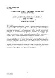
Figure 4-1 shows the schematic of the dust<br />
resistivity measurement setup. Experiments<br />
are carried out us<strong>in</strong>g two electrodes, made up<br />
of a porous s<strong>in</strong>tered material to facilitate the<br />
humidity equilibrium between the dust layer<br />
and the surround<strong>in</strong>g gas <strong>in</strong>side the measur<strong>in</strong>g<br />
chamber. The dust sample was placed on the<br />
lower electrode while the upper electrode<br />
served as the counter electrode electrode. It<br />
was connected to a laboratory high voltage unit<br />
(He<strong>in</strong>z<strong>in</strong>ger PNC 40000-5 ump). Air passes
through a temperature controlled water bath<br />
which is then <strong>in</strong>troduced <strong>in</strong>to the test chamber.<br />
A digital thermometer<br />
Particle size distribution of the test samples<br />
was measured us<strong>in</strong>g a laser granulometer<br />
(CILAS 715) by dispers<strong>in</strong>g the sample <strong>in</strong>to the<br />
water. Scann<strong>in</strong>g electron microscope pictures<br />
of the samples are also presented (Fig. 4-3).<br />
Fig. 4-1: Schematic of the dust resistivity<br />
measurement setup<br />
was used to record the air temperature. Gas<br />
temperature enter<strong>in</strong>g the test chamber, was<br />
successively raised by an air heater control.<br />
The temperature ramp rate was adjusted to<br />
< 3 °C/m<strong>in</strong>ute to achieve an acceptable<br />
stability of humidity axchange between the<br />
dust layer and the environmental gas [5-6].<br />
The measurement chamber was <strong>in</strong>sulated<br />
properly to m<strong>in</strong>imize the heat losses. Dust<br />
temperature was measured by us<strong>in</strong>g a<br />
thermocouple (ERO Electronic) which<br />
contacted the outer r<strong>in</strong>g of the lower electrode.<br />
A digital multi-meter was used to measure the<br />
voltage between the electrodes. Another digital<br />
multi-meter was used to register the current<br />
flow<strong>in</strong>g through the dust layer.<br />
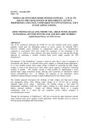
Figure 4-2 presents the arrangements of the<br />
electrodes to be used <strong>in</strong> the two different<br />
resistivity measurement methods: p<strong>in</strong>ot-plate<br />
and plate-plate. The lower plate type dust<br />
carrier electrode was fixed to the bottom of the<br />
chamber while the upper p<strong>in</strong>t or plate type<br />
electrode was adjustable. Further detail of this<br />
setup can be found <strong>in</strong> Wiggers et al. [5-6].<br />
Fig. 4-2: Electrode arrangement <strong>in</strong> dust<br />
resistivity measurement chamber, left: needleplate<br />
setup, right: plate-plate setup<br />
Fig. 4-3: SEM pictures of the test materials<br />
5 Experimental Results and<br />
Discussion<br />
5.1 Influence of measurement<br />
method on dust resistivity<br />
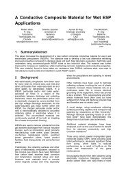
Fig. 5-1 shows the resistivity of the fly ash and<br />
the current density under air dew po<strong>in</strong>t 20°C,<br />
as a function of temperature, us<strong>in</strong>g two<br />
resistivity measurement methods: po<strong>in</strong>t-plate<br />
and plate-plate. In po<strong>in</strong>t-plate method, the<br />
upper electrode was adjusted 40 mm on top of<br />
the dust layer while <strong>in</strong> the plate-plate method,<br />
the upper electrode was placed <strong>in</strong> direct<br />
contact with the dust layer with great care to<br />
m<strong>in</strong>imize the compression of dust layer. In first<br />
method, the air resistivity was subtracted from<br />
air+dust resistivity. Results show that the po<strong>in</strong>tplate<br />
method delivers much higher resistivity<br />
than the plate-plate method e.g. by a factor of<br />
6 at temperature of 120 °C. Both methods lead<br />
to the onset of back corona. One possible<br />
reason for the different resistivity is a marg<strong>in</strong>al<br />
compaction of the dust layer by the upper<br />
electrode. For the plate-plate method, the<br />
weight of the upper electrode def<strong>in</strong>es the<br />
pressure on the top of the dust layer while <strong>in</strong><br />
po<strong>in</strong>t-plate method, the electric w<strong>in</strong>d, also<br />
termed as ionic w<strong>in</strong>d <strong>in</strong> the literature may exert<br />
some force. Kercher [12] analyzed the strength<br />
and flow profile of the electric w<strong>in</strong>d <strong>in</strong> the po<strong>in</strong>tplate<br />
method as a function of the shape of the<br />
po<strong>in</strong>t electrode and distance between the dust<br />
layer and the po<strong>in</strong>t electrode. He established a<br />
relationship between air velocity ‘u’ and the<br />
current density ‘j’ through the dust layer as:<br />
u ≈ j<br />
(7)
expanded itself between 70 °C and 195 °C.<br />
Desorption rate <strong>in</strong>creases with <strong>in</strong>creas<strong>in</strong>g<br />
temperature and achieves a peak value at<br />
T ≈ 125 °C. This is caused by desorption of<br />
physically adsorbed water molecules [10].<br />
Fig. 5-1: Comparison of dust resistivity<br />
measurement methods: po<strong>in</strong>t-plate and plateplate,<br />
upper two curves: dust resistivity as a<br />
function of measurement method and temperature,<br />
lower two curves: current density as a<br />
function of measurement method and<br />
temperature, layer thickness: 3 mm, air dew<br />
po<strong>in</strong>t: 20 °C<br />
Another reason for higher resistivity <strong>in</strong> po<strong>in</strong>tplate<br />
method is the higher water desorption<br />
rate as the dust layer is directly exposed to the<br />
surround<strong>in</strong>g air while <strong>in</strong> the plate-plate method,<br />
it is covered by the upper electrode although<br />
made from porous s<strong>in</strong>ter metal.<br />
5.2 Influence of mode of<br />
temperature variation on dust<br />
resistivity<br />
The observation <strong>in</strong> Fig. 5-1 was further<br />
exam<strong>in</strong>ed perform<strong>in</strong>g the experiment not only<br />
for the case of water desorption but also for the<br />
adsorption (method: plate-plate). This test was<br />
first performed by <strong>in</strong>creas<strong>in</strong>g the air<br />
temperature up to a maximum of 250 °C and<br />
then subsequently decreas<strong>in</strong>g it down to 80 °C<br />
(Fig. 5-2). The two lower curves show the<br />
current density as a function of ascend<strong>in</strong>g and<br />
descend<strong>in</strong>g temperatures. The resistivity<br />
results show relative higher values for the<br />
descend<strong>in</strong>g temperatures but only for low<br />
temperatures, i.e. T < 160 °C. For higher<br />
temperatures, both curves exist very close to<br />
each other. It can be expla<strong>in</strong>ed on the basis of<br />
irreversibility <strong>in</strong> isotherms obta<strong>in</strong>ed with water<br />
vapour as adsorbate and the fly ash as<br />
adsorbent [10]. Further, the back corona was<br />
observed <strong>in</strong> both modes: for ascend<strong>in</strong>g<br />
temperatures, it lasted from 90 °C to 195 °C<br />
whereas for descedn<strong>in</strong>g temperatures, it<br />
Fig. 5-2: Upper: dust resistivity as a function of<br />
temperature, mode of operation (ascend<strong>in</strong>g/<br />
descend<strong>in</strong>g temperature) and humidity, lower:<br />
current density as a function of temperature,<br />
mode of operation (ascend<strong>in</strong>g/descend<strong>in</strong>g<br />
temperature) and humidity, air po<strong>in</strong>t po<strong>in</strong>t:<br />
20 °C, layer thickness: 3 mm, method: plateplate<br />
Desorption rate starts decreas<strong>in</strong>g with further<br />
<strong>in</strong>crease <strong>in</strong> temperature which is controlled by<br />
the removal of water molecules from the <strong>in</strong>ner<br />
body of particles. For descend<strong>in</strong>g temperature,<br />
water starts to adsorb on particle surface but<br />
probably not so quick as it desorbed <strong>in</strong> case of<br />
ascend<strong>in</strong>g temperature. Rothenberg et al. [10]<br />
obta<strong>in</strong>ed the hysteresis loops for adsorption<br />
and desorption of pure water vapour to fly ash<br />
sample us<strong>in</strong>g BET measurement method. At<br />
constant temperature (20 °C), for the<br />
desorption case, the amount of water residual<br />
<strong>in</strong> the sample was 12.5 mg/g while it is<br />
reduced to 6 mg/g for adsorption. The specific<br />
surface area (S g ) of this material was 2.1 m²/g.<br />
In our case, S g was measured with a Gem<strong>in</strong>i<br />
2360 surface area analyzer, us<strong>in</strong>g BET<br />
measurement method and found to be 1.069<br />
m²/g.<br />
5.3 Influence of particle size on<br />
dust resistivity<br />
In Fig. 5-3, resistivity of the four glass samples<br />
with mean particle sizes, d p,50 75, 112, 278 and<br />
394 µm, has been plotted aga<strong>in</strong>st the air<br />
temperature under current density 0.5 mA/m²<br />
and air dew po<strong>in</strong>t 40 °C. The results show that<br />
the resistivity is different for different mode of<br />
experiments (ascend<strong>in</strong>g and descend<strong>in</strong>g) up to
air temperature T = 170 °. In temperature<br />
range of T = 180-190 °C, all curves stay fairly<br />
close to each other. For low temperatures i.e.<br />
T < 170 °C, the current flows through the<br />
particle surface which is strongly <strong>in</strong>fluenced by<br />
the presence of water layer on the particle<br />
surface. At higher temperatures, water desorbs<br />
from the particle surface and the conduction<br />
takes place through the core of the particles.<br />
Here, the chemical composition of the material<br />
presence of higher moisture content for the<br />
smaller particles due to their higher spec.<br />
surface area could be one possible reason for<br />
the observations <strong>in</strong> Fig. 5-3.<br />
Table 5-1: Porosity of the test glass samples<br />
d p (µm) 75 112 278 394<br />
ε (%) 37.9 36.9 35.1 35.6<br />
Fig. 5-3: Influence of particle size on dust<br />
resistivity, s = 3 mm, method: plate-plate<br />
plays a dom<strong>in</strong>ant role. Further, <strong>in</strong> case of<br />
ascend<strong>in</strong>g temperatures, the resistivity of the<br />
smaller particles is less than the bigger ones<br />
for low temperatures i.e. T < 170 °C, while <strong>in</strong><br />
case of descend<strong>in</strong>g temperatures, the smaller<br />
particles have higher resistivity. Additionally,<br />
the difference <strong>in</strong> the resistivity for ascend<strong>in</strong>g<br />
and descend<strong>in</strong>g temperatures gets smaller<br />
with the <strong>in</strong>crease <strong>in</strong> the particle size. To<br />
determ<strong>in</strong>e the possible reasons of such<br />
phenomena, firstly, the porosity ‘ε’ of the<br />
samples was considered. Accord<strong>in</strong>g to Stieß<br />
[13], the porosity of an irregular pack<strong>in</strong>g of the<br />
mono-dispersed particles does not change<br />
remarkably for the non-cohesive and free<br />
flow<strong>in</strong>g granular media with particle size above<br />
100 µm. Porosity of our test samples was<br />
calculated experimentally and the results are<br />
shown <strong>in</strong> Table 5-1. It can be seen that it does<br />
not change by big marg<strong>in</strong>s with change <strong>in</strong> the<br />
particle size. Under such circumstances, it can<br />
be concluded <strong>in</strong> our case that the porosity was<br />
not amongst the highly <strong>in</strong>fluenc<strong>in</strong>g parameter.<br />
Next, the spec. surface area was considered<br />
as the <strong>in</strong>fluenc<strong>in</strong>g parameter. Naganuma et al.<br />
[14] measured the spec. surface area of the<br />
four glass particle samples with mean particle<br />
diameters of 26, 42, 59 and 85 µm with N 2 and<br />
Kr gases us<strong>in</strong>g a surface area pore size<br />
analyzer (BEL SORP 36, Nihon Bell Corp.,<br />
Tokyo, Japan). They found that the specific<br />
surface of the glass particles <strong>in</strong>creases with<br />
decrease <strong>in</strong> the average particle size. The<br />
5.4 Influence of air humidity on<br />
dust resistivity<br />
To understand the role of water content for the<br />
dust resistivity more clearly, the fly ash sample<br />
was tested under three different air dew po<strong>in</strong>ts<br />
‘T d ’ i.e. 25 °C, 40 °C and 55 °C respectively.<br />
For the case of ‘T d ’: 25 °C, the material shows<br />
the maximum resistivity 2 x 10 12 Ω•cm at air<br />
temperature 130 °C (Fig. 5-4). The onset of<br />
back corona was observed for the temperature<br />
range 90 – 190 °C. Further, ‘T d ’ was <strong>in</strong>creased<br />
to 40 °C, keep<strong>in</strong>g the same other experimental<br />
conditions. In do<strong>in</strong>g so, the maximum resistivity<br />
decreased to 5 x 10 11 Ω•cm at the same air<br />
temperature. The back corona region was also<br />
reduced between 115 – 170 °C. Complete<br />
elim<strong>in</strong>ation of back corona was observed with<br />
dew po<strong>in</strong>t 55 °C while the maximum resistivity<br />
was also decreased to 2 x 10 11 Ω•cm.<br />
5.5 Visualization of back corona<br />
To visualize the onset of back corona dur<strong>in</strong>g<br />
the resistivity measurement, a high speed<br />
camera HSS3 LaVision was added to the<br />
experimental setup expla<strong>in</strong>ed <strong>in</strong> section 4.<br />
Experimental conditions were set to the dust<br />
layer thickness 3 mm and air dew po<strong>in</strong>t 20 °C<br />
us<strong>in</strong>g po<strong>in</strong>t-plane method. At an <strong>in</strong>ter-electrode<br />
distance of 29 mm, the electric w<strong>in</strong>d was too<br />
strong, which resulted <strong>in</strong> particle reentra<strong>in</strong>ment<br />
right from the beg<strong>in</strong>n<strong>in</strong>g of the<br />
test. At an <strong>in</strong>ter-electrode distance of 41.5 mm,<br />
it was possible to visualize the back corona <strong>in</strong><br />
form of t<strong>in</strong>y light glows on the dust layer<br />
surface. <strong>Back</strong> corona started at air temperature<br />
80 °C and lasted till 180 °C. At the start of the<br />
experiment, the upper surface of the dust layer<br />
was almost smooth which can be seen <strong>in</strong> Fig.<br />
5-5 a. It also shows the light glow at just the<br />
start of the back corona <strong>in</strong> the system. Due to<br />
the cont<strong>in</strong>uous back corona, a small amount of<br />
dust particle was cont<strong>in</strong>uously blown <strong>in</strong>to the<br />
air from the upper surface of the dust layer
which made it very rough. It is shown <strong>in</strong> Fig. 5-<br />
5 b, which also shows the blow or reentra<strong>in</strong>ment<br />
of the dust particles <strong>in</strong>to the<br />
surround<strong>in</strong>g environment as a result of the<br />
back corona.<br />
Fig. 5-4: Influence of air humidity on the dust<br />
resistivity, s = 2.5 mm, method: plate-plate<br />
6 Literature<br />
[1] Lloyd, D. A.; <strong>Electrostatic</strong> precipitator handbook;<br />
IOP Publish<strong>in</strong>g Ltd. England; 1998; pp. 65-67<br />
[2] Instruction manual; Wahlco resistivity probe,<br />
revised version; USA;1985<br />
[3] White, Harry J.; Industrial electrostatic<br />
precipitators; Addison-Wesley Publish<strong>in</strong>g<br />
Company, Inc.; USA; 1963<br />
[4] Rose, H.E. and Wood A. J.; An <strong>in</strong>troduction to<br />
electrostatic precipitation <strong>in</strong> theory and practice;<br />
Constable & Company Ltd.; England; 1956; pp.<br />
123-127<br />
[5] Wiggers, H.; Measurement of dust resistivity -<br />
<strong>Back</strong> corona <strong>in</strong> electrostatic precipitators; VGB<br />
PowerTech, No. 3; Germany; 2007; pp. 93-96<br />
[6] Wiggers, H. and Nasri, S.; Staubwiderstandsmessungen<br />
bei Elektrofiltertypischen Stromdichten;<br />
Gefahrstoffe - Re<strong>in</strong>haltung der Luft 68,<br />
No. 5; Germany; 2008; pp. 177-181<br />
[7] Lee, J. K., Hyun, O. C. and Lee, J. E.; KSME<br />
International Journal, Volume 15, No. 5; South<br />
Korea; 2001; pp. 630-638<br />
[8] Miller, J., Hoferer, B. and Schwab, A.; Fe<strong>in</strong>staubabscheidung<br />
<strong>in</strong> betriebsoptimierten<br />
Elektrofiltern, Teil II, PEF – Projekt;<br />
Europäisches Forschungszentrum für<br />
Maßnahmen zur Luftre<strong>in</strong>haltung; Germany; 1977<br />
[9] Hoferer, B. and Schwab, A.; Local occurance of<br />
back corona at the dust layer of electrostatic<br />
precipitators; Conference on electrical <strong>in</strong>sulation<br />
and dielectric phenomena; 1977; pp. 93-96<br />
[10] Rothenberg, S. J. and Cheng, Y. S.; Coal<br />
combustion fly ash characterization - Rates of<br />
adsorption and desorption of water; The Journal<br />
of Physical Chemistry, Vol. 84, No. 12; USA;<br />
1980; pp. 1644-1649<br />
[11] Krupa, A., Lackowski, M. and Czech, T.; Dust<br />
particles motion <strong>in</strong> back discharge; Journal of<br />
Physics, Conference Series 142; Poland; 2008;<br />
pp. 1-4<br />
[12] Kercher, H.; Elektrischer W<strong>in</strong>d, Rücksprühen<br />
und Staubwiderstand als E<strong>in</strong>flußgrößen im<br />
Elektrofilter; VDI-Z. Series 6 Nr. 27, Germany;<br />
1970; pp. 52<br />
[13] Stieß, M.; Mechanische Verfahrenstechnik 1,<br />
2nd Edition; Spr<strong>in</strong>ger-Verlag Berl<strong>in</strong>; 1998; pp.<br />
64-67<br />
[14] Nganuma, T., Kagawa, Y.; Effect of particle size<br />
on light transmittance of glass particle dispersed<br />
epoxy matrix optical composites; Acta mater.<br />
Vol. 47, No. 12; Japan; 1999; pp. 4321-4327<br />
Fig. 5-5: Visualization of back corona <strong>in</strong> the fly<br />
ash layer, <strong>in</strong>ter-electrode distance: 41.5 mm,<br />
air dew po<strong>in</strong>t: 20°C, a) Visible light glow, b)<br />
Blow or re-entra<strong>in</strong>ment of the dust particles